Article

Optimal Design of the Electroadhesion Pad with a Dual-Insulating Layer for Climbing Robots

1
Smart Manufacturing System R&D Department, Korea Institute of Industrial Technology, Cheonan-si 31056, Korea
2
Department of Mechatronics Engineering, Korea Polytechnic University, Siheung-si 15073, Korea
*
Authors to whom correspondence should be addressed.
Actuators 2022, 11(2), 36; https://doi.org/10.3390/act11020036
Submission received: 22 November 2021 / Revised: 12 January 2022 / Accepted: 18 January 2022 / Published: 25 January 2022
(This article belongs to the Special Issue Actuators for Climbing Robotics)

Abstract

:
The electroadhesion pad is mainly studied for applications, such as climbing robots and grippers. In this paper, we present our study with the confirmation of the adhesion properties of the electroadhesion pad with a double-insulating layer, pad modeling, and optimal design. Modeling and analysis consider the air layer generated during the manufacturing of both conventional single-insulated structures and dual-insulated structures. Through the finite element analysis simulation, the characteristics of the electroadhesion were verified, and modeling verification was performed, based on the variables that had a large influence as follows: applied voltage, electrode area, dielectric thickness, and permittivity. The electrode is made of aluminum, the substrate is made of silicon, and the dielectric is made of polyimide film. An error of up to 8.3% was found between the modeling and simulation. The optimization results were validated based on a pad applied to a climbing robot measuring 320 × 480 mm ² and weighing 2.8 kg . As a result, the optimal pad design resulted in an error of 7.3% between the modeling and simulation.

1. Introduction

The electroadhesion pad is one of the methods for applying the electrostatic adsorption method to various adsorption targets. Recently, electroadhesion pads have been applied to various applications, such as climbing robots [1,2] for exploration and inspection and grippers [3,4] for pick-and-place systems. Similar adsorption and adhesion methods, such as pneumatic, hydraulic, and magnet [5,6,7], have been developed, but in the case of the pneumatic method, there is a reduction in adsorption force and an increase in noise problems in materials with a rough object to be adsorbed. It is noteworthy that the cost is high, and for the magnet method, the limitations of the applied object are clear, depending on the material characteristics. As a solution to these adsorption problems, an electroadsorption method has been proposed and is generally studied in the form of an electroadhesion pad.
In general, an electroadhesion pad has a simple configuration that can be implemented with insulators, dielectrics, and electrodes [8]. In addition, since the adsorption works in almost the same way as the electrostatic chuck, the (+) electrode and the (−) electrode are repeatedly arranged in the pad, according to the bipolar type of the electrostatic chuck, which is a verified form. At this time, an electric field is formed by a high voltage of several kV applied to the electrode, and an electrostatic force, due to dielectric polarization, is generated in the dielectric of the bonding object and the pad to obtain an electroadhesion force. At this time, the maximum electroadhesion force of the pad is limited due to insulation breakdown and discharge caused by excessive high voltage application. This means that the electroadhesion method may be relatively sensitive to the area of action of the adsorption force compared to other adsorption methods, and there are restrictions on the size and weight of the applied system. To improve this, a double insulation structure with an insulating layer added between the (+) electrode and (−) electrode was proposed in the previous paper [9], and it was shown that it was applied and driven to a prototype of a large climbing robot by improving the discharge potential and maximum adsorption capacity. However, the theoretical analysis model of the generated electroadhesion force, according to the design of the proposed double-insulated electrostatic adsorption pad, is not accurate, and there are many differences between the generated adsorption force and the theoretical value for the existing pad [10].
In this paper, verification of the proposed dual-insulated electroadhesion pad for large-scale application and improvement of electroadhesion power is performed. Section 2 proceeds with the principle and experimental verification of the proposed dual-insulated electroadhesion pad. In Section 3, the proposed pad mathematical modeling is verified based on the derivation of the Ansys Maxwell finite element analysis. In Section 4, the optimal design of the pad for the climbing robot system is performed and verified through cross-verification between modeling and optimal design analysis data.

2. Dual Electroadhesion Pad

2.1. Principle of Dual Electroadhesion Pad

Electroadhesion is defined as the electrostatic attraction between the planes of two objects with a potential difference. Electroadhesion force is generated using the electrostatic induction phenomenon of a capacitor in the form of a pad in general. When the contact surface is a conductor, a charging phenomenon occurs, whereas an insulator exhibits dielectric polarization. Moreover, a conductor obtains a strong electroadhesion force due to a relatively large amount of internal free electron movement, whereas an insulator obtains a relatively low electroadhesion force.
In the pad structure shown in Figure 1a, by applying a high voltage to the electrode, if the electrode and the adsorption target surface are considered as a pair of parallel plates, the entire pad can be modeled as two parallel capacitors. Since the same amount of charge is accumulated between the two plates with different poles, a surface charge density of the same size is formed. Figure 1c shows the formed charge with an electrostatic force being generated. Figure 1b shows that the dual-insulated electroadhesion pad has a structure with an insulator added between the electrodes. In order to realize the possibility of a higher voltage application and to prevent discharge in the single-insulated structure, a structure for high density is required as shown in Figure 1a. If there is no air layer formed between the electroadhesion pad and adsorption target, the applied electroadhesion force can be expressed as the following Equation (1):
F = ε 0 ε r   A V 2 2 d
Electroadhesion force can be induced by differentiating the applied electrostatic energy with respect to the distance between the electrode inside the pad and the attachment target. F is the electroadhesion force, ε 0 is the permittivity in vacuum, ε r is the relative permittivity of the dielectric used, A is the area of the electrode, V is the applied voltage, and d is the distance between the electrode and the wall.

2.2. Experimental Validation of the Dual Electroadhesion Pad

In general, according to Equation (1) above, a higher electroadhesion force is exhibited as a high voltage and is applied in a single-insulation structure as opposed to a dual-insulation structure. However, there is a limit of charge accumulation, and there is a limit of applied voltage due to a discharge phenomenon problem, according to a manufacturing method [11,12]. It has been verified based on numerous previous studies that the increase rate of the electroadhesion force decreases when a high voltage is applied. Therefore, as shown in Figure 2, both the numerical values and experimental data of the pad for the single- and dual-insulation structures need to be compared and verified.
Table 1 shows that the experimental setup in which the aluminum tape, polyimide film, etc., which are readily available in the vicinity, were manually performed. As shown in Figure 2, the mathematical data showed that the electroadhesion capacity of the single-insulating structure was excellent, but there was a difference in the data values through performing the experiment. At a low applied voltage, the single-insulating structure still showed high adsorption power, but the difference in electroadhesion power decreased as the applied voltage was increased, and the limit of the maximum applied voltage was confirmed due to the discharge phenomenon occurring at 6 kV. When the applied voltage was 6 kV or higher and the dual-insulated electroadhesion pad exhibited the electroadhesion force, it was confirmed that the maximum electroadhesion force was higher than that of the conventional pad. Figure 3 illustrates the setting for the method of measuring the electroadhesion force for the electroadhesion force test in this section.

3. Modeling

Before the optimal design of the dual-insulated electroadhesion pad, it is necessary to confirm and verify the pad characteristics for the variables affecting the electroadhesion force. Therefore, this section aims to confirm the characteristics of each parameter of the pad and to confirm the accuracy between the proposed modeling and the finite element analysis data.

3.1. Analytical Modeling of Electroadhesion Pad

In 
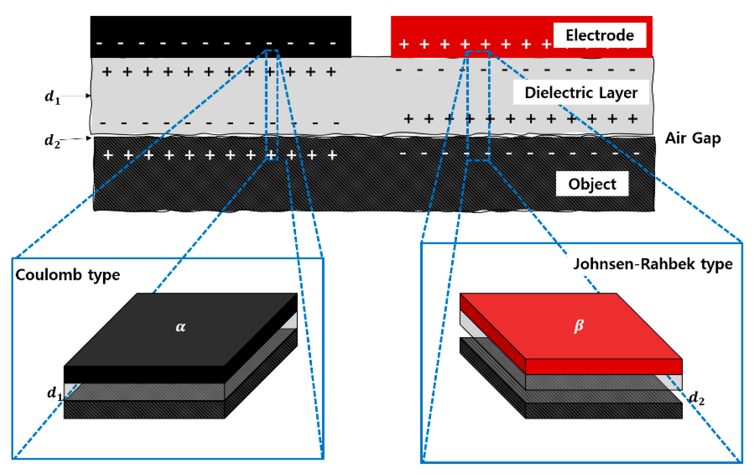
Section 2, the electroadhesion force could be derived as shown in Equation (1) by Coulomb’s law and the law of energy conservation. Contrary to the previous assumption, since the pad and the attachment surface cannot be in an ideal close contact in the real environment, it can be modeled separately by the Coulomb force and the Johnsen–Rahbek force [13,14], as shown in Figure 4, considering the formed air layer. d 1 denotes the thickness of the dielectric between the electrode and the wall surface of the pad, and d 2 denotes the thickness of the air layer formed between the pad and the wall surface. α and β represent the areas of the Coulomb force and the Johnson–Rahbek force, respectively. Therefore, Equation (2) below expresses the modeling of the single-insulating electroadhesion pad:
F z = ε 0 ε r   α V 2 2 d 1 2 + ε 0   β V 2 2 d 2 2  
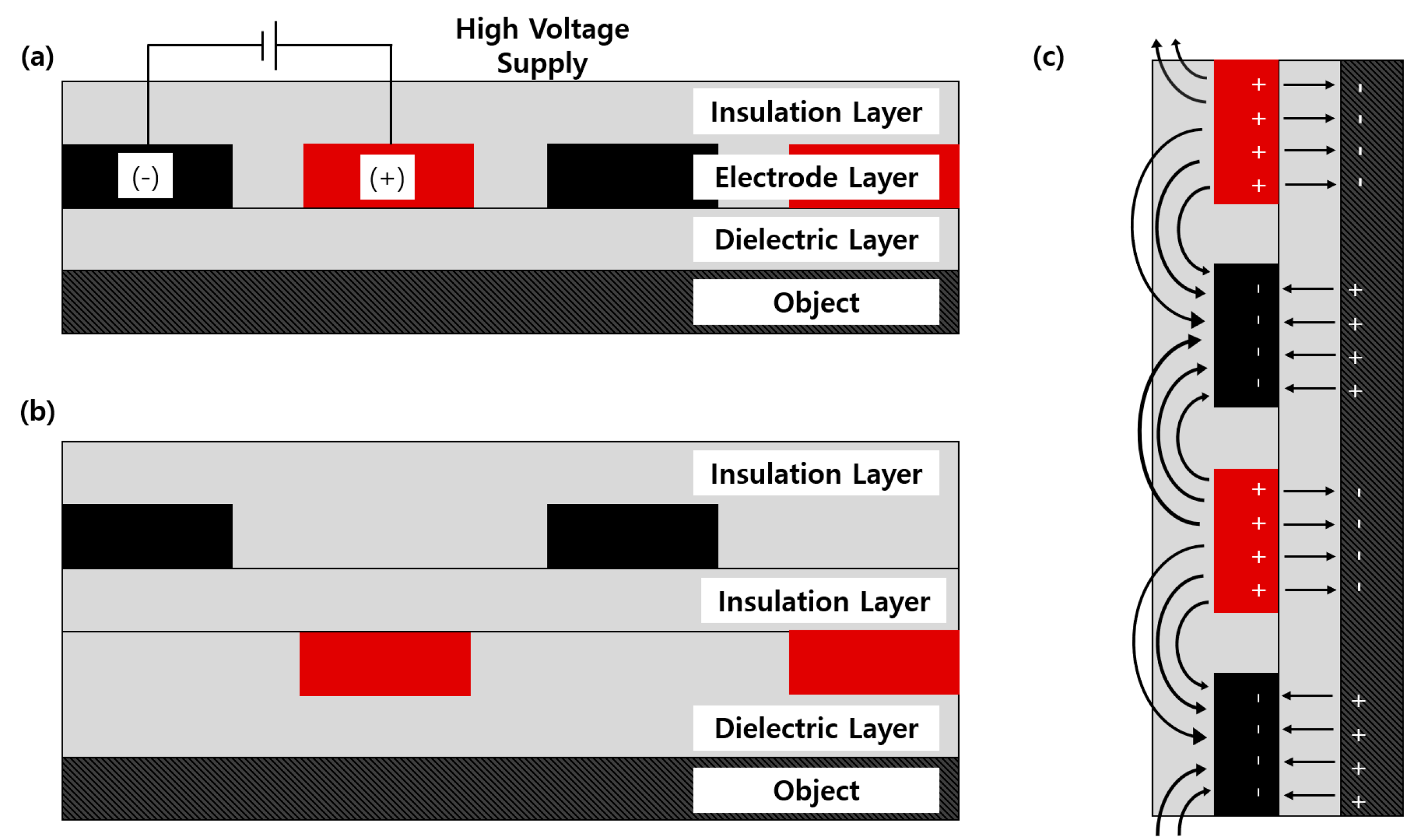
The modeling of the double-insulated electroadhesion pad is the same as that of the single-insulated structure. Figure 5 and Equation (3) illustrate how the model is modeled, while Figure 5a,c shows the presence or absence of an air gap in the dual-insulated structure, and Figure 5b,d shows the presence or absence of an air gap in the single-insulated structure.
F z = ε 0 ε r   A 1 V 1 2 2 d 1 2 + ε 0 ε r   A 2 V 2 2 2 d 2 2 + ε 0   A 3 V 1 2 2 d 3 2 + ε 0   A 4 V 2 2 2 d 4 2
A 1 is the area where a single dielectric layer is present, and ideal adhesion is achieved. A 2 is the area where the dielectric layer and insulating layer exist, and, thereby, ideal adhesion is achieved. A 3 is the area where a single dielectric layer is present, and an air layer is present. A 4 is the area where the dielectric layer and the insulating layer are present, and, thereby, the air layer is present. Figure 5 shows that d 1 to d 4 refer to the thickness of the dielectric layer, insulating layer, and the air layer, respectively.
When the electroadhesion force according to each variable in Table 2 is confirmed through the Ansys Maxwell, each characteristic and influence can be considered and applied to the optimal design.
The design and finite element analysis to confirm the characteristics of the electrostatic adsorption pad were conducted in the Ansys Maxwell. The solution type was set to Electrostatic. Meshing was set to a highly robust volumetric meshing (TAU), provided by the Ansys Maxwell, and the bonding target is made of 0.6 mm thick silicon material. To consider the air layer of the proposed modeling equation, the thickness was set to 5 μm to confirm the electrostatic field and the applied force. Figure 6 shows the designs of single- and dual-insulated electroadhesion pads composed of two electrodes in the Ansys Maxwell. In this study, for a fast simulation process, the simplified pad shape was used, as shown in Figure 7.
As a result, it was confirmed that when the electrode area was set to increase the electrode length, the larger the area was, the larger the electroadhesion became for the area. It is confirmed that as the electrode width increases, the electroadhesion per area decreases, and the applied voltage increases in the form of a quadratic curve. The change was insignificant compared to the difference in the range of variation in electrode thickness, and as the distance between the electrodes increased, the electroadhesion decreased. Likewise, as the thickness of the dielectric increased, the electroadhesion decreased, and as the dielectric constant increased, the electroadhesion increased. These are predictable results through the formula derived above. However, when the influence on the change in the adsorption force is confirmed with this, key parameters, such as applied voltage, electrode area, dielectric thickness, and permittivity, are selected as key parameters for the pad optimization, and then modeling verification and optimal design are performed.
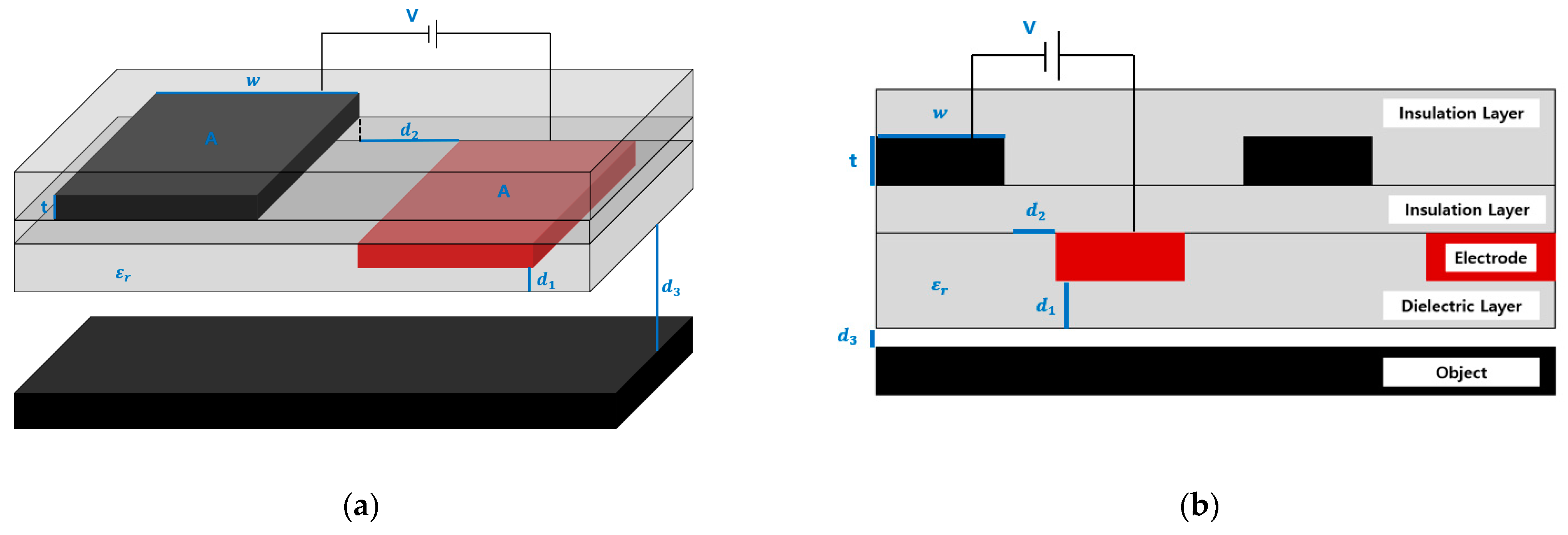
Each parameter was selected according to the pad structure and formula and can be confirmed, as illustrated in Figure 7. Each parameter was selected as the applied voltage V , the electrode area A , the electrode width w, the electrode thickness t , the dielectric thickness d 1 , the inter-electrode distance d 2 , and the dielectric constant ε r . Figure 7 shows the design of the reference pad with an applied voltage of 2 kV , an electrode area of 9600 mm 2 , an electrode width of 48 mm , an electrode thickness of 16 μ m , a dielectric thickness of 100 μ m , an inter-electrode distance of 5 mm , a dielectric constant of 3.5 F / m , and an aluminum electrode. Table 2 represents the range for experiments in future studies for each parameter, and 4–5 samples were used.
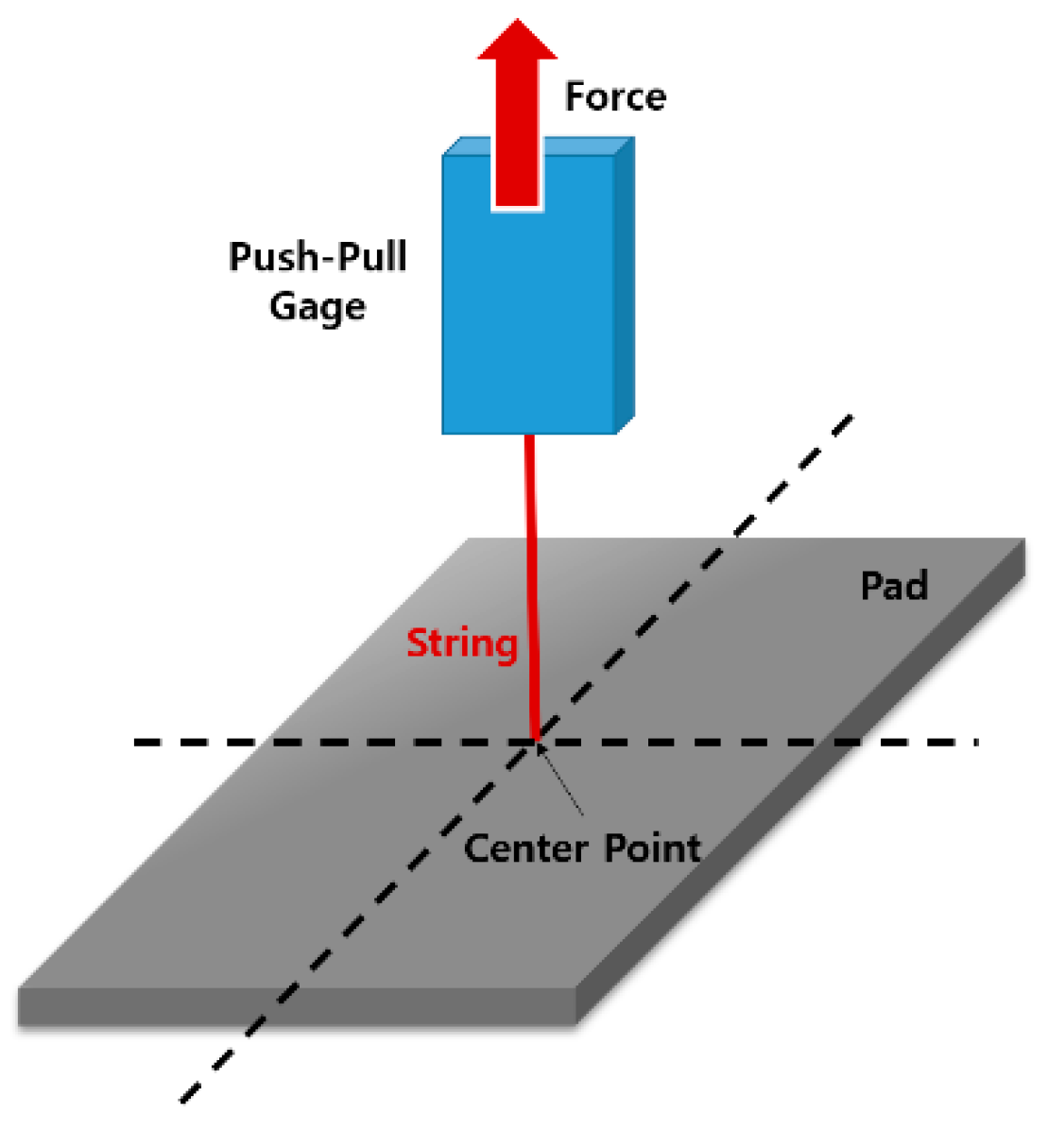
Analysis data for each parameter are compared by measuring the force acting between the pad electrode and the attachment target. Figure 8 and Figure 9 show the simulation results for meshing, applied voltage, electric field, and surface force density to which the reference setting of the pad, according to each structure, is applied. In Figure 8a and Figure 9a, fine meshing is made on the edge portions of the electrode where the electric field is applied. Figure 8b and Figure 9b show that the potential difference of the applied voltage is set to be 2 kV. Figure 8c,d and Figure 9c,d show that a uniform force acts from the electrode to the suction pad for single insulation and that the force generated at one electrode is relatively reduced by the added insulation layer for dual insulation.

3.2. Validation of Modeling

Modeling verification is performed based on the error between the modeling Equation (3) and the Ansys Maxwell simulation result within the following major parameters: the applied voltage, electrode area, dielectric thickness, and permittivity.
In Figure 10, it is confirmed that the numerical values by modeling for each parameter and the graph tendencies of the electrostatic field analysis results are almost identical. Moreover, Table 3 confirms that all the errors for modeling and Equation (3) are appropriate as all errors were less than 10%. The electrostatic field analysis was simulated with an air gap of 5 μm. However, the modeling was calculated ignoring the 5 μm air gap. Therefore, some errors occurred, as shown in Table 3.

4. Optimal Design

4.1. Parameter Analysis

In the previous part, it was explained that the electrostatic adsorption pad is being applied in various applications, such as climbing robots and grippers. Among them, research on climbing robots is being conducted for the purpose of inspecting and exploring high-value facilities and structures. However, due to the limited maximum adsorption force, which counts as a disadvantage of the electroadhesion pad, the electroadhesion-type climbing robot, in general, has small-size and lightweight characteristics. However, the suction power has been improved with the dual-insulated electroadhesion pad, making it possible to apply and operate a larger scale climbing robot.
The proposed climbing robot has the potential to be applied for the courier use of transporting and mounting items. It is expected that the composition will be composed of a total weight of 3 kg. However, since there is a difficulty in manufacturing and applying the applied pad when loading a separate parcel, it is composed of a simple treadmill-type 2.8 kg robot specification.
Table 4 is the parameters of the prototype climbing robot used in the study on the operation of the climbing robot to which the dual-insulated electroadhesion pad is applied. The climbing robot is designed in a shape similar to many climbing robots to which electroadhesion is applied, and its operation has been verified as a treadmill-type wheel structure and pad-applied climbing robot. For the application of the optimally designed dual-insulated electroadhesion pad in future studies, verification and experimental verification through finite element analysis should be conducted. In this study, only the finite element analysis verification of the dual-insulated electroadhesion pad to be applied to the climbing robot is carried out.
As the proposed climbing robot has a weight of about 2.8 kg , as shown in Table 4, a pad that exhibits an electroadhesion force of at least 30 N should be designed. The equation obtained in the modeling process can be set as a cost function for the optimal design as it is expressed in Equation (4):
f c . f = ε 0 ε r   A 1 V 1 2 2 d 1 2 + ε 0 ε r   A 2 V 2 2 2 d 2 2 + ε 0   A 3 V 1 2 2 d 3 2 + ε 0   A 4 V 2 2 2 d 4 2  
Table 5 is the range of each parameter to reach 30 N of an electroadhesion force. In this range, the boundary is set so that the pad can be manufactured for verification through application to the climbing robot and driving experiment.

4.2. Parameter Analysis

Sequential Quadratic Programming (SQP) is used for an optimal design that meets the conditions. Using Matlab for the SQP algorithm, as shown in Figure 11 and Table 6, the optimal value for each parameter that satisfies the cost function value of 30 N can be confirmed and checked.
The SQP, which is one of the optimal design methods, calculates the changes in the objective function of the second-order form and the constraint of the first-order form that vary slightly, combining them into an optimized gain function. SQP has the advantage of continuously solving the Quadratic Programming (QP) method to find the search direction from the current design point as well as continuously guaranteeing the optimization value for the design variable values. The cost function is determined by the electroadhesion properties of the electrostatic adsorption pad. Therefore, since it is examined within the modeling Equation (3) of the dual-insulation pad proposed for electroadhesion improvement, the cost function is the same as Equation (3), as shown in Equation (4).
The permittivity is set as a fixed variable, and although the final value is slightly different from the optimal design value, it is a value set for the ease of pad fabrication in the subsequent experimental verification process.
It was designed according to the optimized pad parameter values for the Ansys Maxwell verification and the reference pad specification used for modeling verification. The following Table 7 is the detailed specification of the pad modeled in the Ansys Maxwell for optimal design verification.
Figure 12a is a pad designed through an optimal design. Figure 12b–d represents the applied voltage, the electric field applied to the pad surface, and the density of the surface electroadhesion force, respectively. At this time, an air layer of 0.5 μ m was set between the pad and attachment target as well.
As a result, Table 8 shows the error of the electroadhesion force for the results of SQP and the Ansys Maxwell analysis. The applied voltage is set to have an error of 0.8%, and the area has an error of 7%, but it is virtually negligible as the error resulted from the electrostatic adsorption force. As a result, the errors of the electroadhesion force were 7.3% with 30 N and 32.2 N, verifying that the optimal design of the pad was appropriate.

5. Conclusions

In order to improve the maximum adsorption force of the existing single-insulated electrostatic adsorption pad, an insulator was added between the electrodes in the pad, and the problems of the discharge phenomenon and the applied voltage limit were greatly improved. Therefore, in order to confirm the possibility of improving the scale of the general electrostatic adsorption applications, the optimal design of a double-insulated electrostatic adsorption pad, applied to the operation of the climbing robot conducted in the previous study, was attempted and verified through the finite element analysis.
For an optimal design, the modeling of a dual-insulated electroadhesion pad was carried out. Coulomb’s law, the energy conservation law, and the Johnsen–Rahbek effect, previously applied to the single-insulated electroadhesion pads, were considered. Assuming there were four cases of the surface between the pad and attachment object, a modeling equation for the dual-insulated electroadhesion pad was derived. Modeling verification was performed by selecting four main parameters for the pad optimization as follows: applied voltage, electrode area, dielectric thickness, and permittivity. In that respective order, 2.5%, 5.2%, 8.3%, and 3.4% showed that modeling was appropriate with an average error of 4.85%. After that, the optimal design was carried out according to the value of 30 N, which is the required electroadhesion force of the pad to be applied to the climbing robot, and the SQP algorithm was applied in Matlab to find the parameter values for the optimal design. As a result, the optimal design of the double-insulated electrostatic adsorption pad was verified, with an error of 7.3% between the optimal design model and the Ansys Maxwell phase analysis values.

Author Contributions

Conceptualization, Y.-J.J.; methodology, Y.-J.J.; software, Y.-J.J.; validation, Y.-J.J. and T.-H.H.; formal analysis, Y.-J.J.; investigation, Y.-J.J.; data curation, Y.-J.J. and T.-H.H.; writing—original draft preparation, Y.-J.J.; writing—review and editing, Y.-J.J. and H.-J.L.; visualization, Y.-J.J.; supervision, K.K.; project administration, H.-J.L.; funding acquisition, H.-J.L. and K.K. All authors have read and agreed to the published version of the manuscript.

Funding

This work is partly supported by the Korea Agency for Infrastructure Technology Advancement (KAIA) grant funded by the Ministry of Land, Infrastructure and Transport (Grant 20CTAP-C157468-02) and by the GRRC program of Gyeonggi province [(GRRC-KPU2020-B02), Multi-material Machining Innovative Technology Research Center].

Institutional Review Board Statement

Not applicable.

Informed Consent Statement

Not applicable.

Data Availability Statement

Not applicable.

Conflicts of Interest

Authors declare no conflict of interest.

References

  1. de Rivaz, S.D.; Goldberg, B.; Doshi, N.; Jayaram, K.; Zhou, J. Inverted and Vertical Climbing of a Quadrupedal Microrobot Using Electroadhesion. Sci. Robot. 2018, 3, 3038. [Google Scholar] [CrossRef] [PubMed] [Green Version]
  2. Liu, R.; Chen, R.; Shen, H.; Zhang, R. Wall Climbing Robot Using Electrostatic Adhesion Force Generated by Flexible Interdigital Electrodes. Int. J. Adv. Robot. Syst. 2012, 10, 36. [Google Scholar] [CrossRef]
  3. Singh, J.; Bingham, P.; Penders, J.; Manby, D. Effects of Residual Charge on the Performance of Electroadhesive Grippers; Springer: Berlin/Heidelberg, Germany, 2016; pp. 327–338. [Google Scholar]
  4. Guo, J.; Elgeneidy, K.; Xiang, C.; Lohse, N.; Justham, L. Soft Pneumatic Grippers Embedded with Stretchable Electroadhesion. Smart Mater. Struct. 2018, 27, 55006. [Google Scholar] [CrossRef]
  5. Bahr, B.; Li, Y.; Najafi, M. Design and Suction Cup Analysis of a Wall Climbing Robot. Comput. Electr. Eng. 1996, 22, 193–209. [Google Scholar] [CrossRef]
  6. Lee, G.; Kim, H.; Seo, K.; Kim, J.; Kim, H.S. Multitrack: A Multi-Linked Track Robot with Suction Adhesion for Climbing and Transition. Robot. Auton. Syst. 2015, 72, 207–216. [Google Scholar] [CrossRef]
  7. Eich, M.; Vögele, T. Design and Control of a Lightweight Magnetic Climbing Robot for Vessel Inspection. In Proceedings of the 2011 19th Mediterranean Conference on Control & Automation (MED), Corfu, Greece, 20–23 June 2011; pp. 1200–1205. [Google Scholar]
  8. Ruffatto, D.; Shah, J.; Spenko, M. Optimization of Electrostatic Adhesives for Robotic Climbing and Manipulation. In Proceedings of the ASME 2012 International Design Engineering Technical Conferences and Computers and Information in Engineering Conference, Chicago, IL, USA, 12–15 August 2012; pp. 1143–1152. [Google Scholar]
  9. Jeong, Y.J.; Kim, K.H.; Huh, H. Robot Application of Electroadhesion Pads with Dual Insulation. J. Korean Soc. Precis. Eng. 2020, 37, 743–750. [Google Scholar] [CrossRef]
  10. Nakamura, T.; Yamamoto, A. Multi-Finger Electrostatic Passive Haptic Feedback on a Visual Display. In Proceedings of the 2013 World Haptics Conference (WHC), Daejeon, Korea, 14–17 April 2013; pp. 37–42. [Google Scholar]
  11. Koh, K.H.; Sreekumar, M.; Ponnambalam, S.G. Experimental Investigation of the Effect of the Driving Voltage of an Electroadhesion Actuator. Materials 2014, 7, 4963–4981. [Google Scholar] [CrossRef] [PubMed] [Green Version]
  12. Koh, K.H.; Sreekumar, M.; Ponnambalam, S.G. Hybrid electrostatic and elastomer adhesion mechanism for wall climbing robot. Elsevier Mechatron. 2016, 35, 122–135. [Google Scholar] [CrossRef]
  13. Guo, J.; Bamber, J.; Chamberlain, M.; Justham, L.; Jackson, M. Optimization and experimental verification of coplanar interdigital electroadhesives. J. Phys. D Appl. Phys. 2016, 49, 41. [Google Scholar] [CrossRef]
  14. Watanabe, T.; Kitabayashi, T.; Nakayama, C. Relationship between Electrical Resistivity and Electrostatic Force of Alumina Electrostatic Chuck. Jpn. J. Appl. Phys. 1993, 32, 864. [Google Scholar] [CrossRef]
Figure 1. Structure of the electroadhesion pad: (a) one insulation layer type; (b) dual-insulation layer type; (c) charge formation on the electroadhesion pad.
Actuators 11 00036 g001
Figure 2. Comparison of experimental and analysis data of the single-insulation pad structure and the dual-insulation pad structure electroadhesion pad: (a) analysis data; (b) experimental data.
Actuators 11 00036 g002
Figure 3. Holding force measurement between the attachment face and the electroadhesion pad.
Actuators 11 00036 g003
Figure 4. Electrostatic induction between the pad and wall: the Coulomb type and the Johnsen–Rahbek type. Depending on the presence or absence of an air layer, it is divided into the Johnsen–Rahbek type and the Coulomb type.
Actuators 11 00036 g004
Figure 5. Structure approximation of the dual-insulation pad for modeling: (a) without gap at (−) electrode; (b) without gap at (+) electrode; (c) with gap at (−) electrode; (d) with gap at (+) electrode.
Actuators 11 00036 g005
Figure 6. Electroadhesion pad modeling: (a) one-insulation layer type; (b) dual-insulation layer type.
Actuators 11 00036 g006
Figure 7. Parameters of the electroadhesion pad: (a) perspective view, (b) cross section view.
Actuators 11 00036 g007
Figure 8. One insulation electroadhesion pad FEM analysis result: (a) meshing; (b) applied voltage; (c) electric field; (d) surface force density.
Actuators 11 00036 g008
Figure 9. Dual insulation electroadhesion pad FEM analysis result: (a) meshing; (b) applied voltage; (c) electric field; (d) surface force density.
Actuators 11 00036 g009
Figure 10. Modeling and analysis data comparison verification: (a) applied voltage; (b) electrode area; (c) dielectric thickness; (d) dielectric permittivity.
Actuators 11 00036 g010aActuators 11 00036 g010b
Figure 11. Modeling and analysis data comparison verification: (a) applied voltage; (b) electrode area; (c) dielectric thickness; (d) dielectric permittivity.
Actuators 11 00036 g011
Figure 12. Optimal design electroadhesion pad FEM analysis result: (a) model design; (b) applied voltage; (c) electric field; (d) surface force density.
Actuators 11 00036 g012
Table 1. Specifications of the electroadhesion pad for an adsorption experiment.
VariableOne InsulationDual InsulationUnit
Electrode area19,20019,200 mm 2
Electrode distance55 mm
Dielectric thickness100100~200 μ m
Applied voltage0~100~10 kV
Electrode materialAluminum foil
Dielectric materialPolyimide film/OHP film
Table 2. Specification of the electroadhesion pad used in the Ansys Maxwell.
VariableSymbolRangeUnit
Applied voltage V 2~10 kV
Electrode area A 9600~19,200 mm 2
Electrode width w 12~48 mm
Electrode thickness t 16~48 μ m
Electrode distance d 2 5~10 mm
Dielectric thickness d 1 100~300 μ m
Air Gap d 3 5 μ m
Relative permittivity ε r 3.5~14
Table 3. Modeling and analysis data comparison verification: error.
Design VariableError (%)
Applied voltage2.5
Electrode area5.2
Dielectric thickness8.3
Dielectric permittivity3.4
Table 4. System parameters for the prototype climbing robots.
DescriptionTarget ValueUnit
Climbing Robot Weight2.8 kg
Climbing Robot Size 320 × 480 mm 2
Electroadhesion Force30 N
Table 5. Constraints for Optimal Design.
Design VariableBoundaryUnit
Applied Voltage2500–3000 V
Electrode Area25,000–30,000 mm 2
Dielectric thickness100–115 μ m
Relative permittivity3.5
Table 6. Optimal dimension and specification for the FEM design model.
ConstraintsOptimal DimensionFinal DimensionUnit
Applied Voltage28752800 V
Electrode Area27,19027,000 mm 2
Dielectric thickness106106 μ m
Table 7. Specification of the optimal electroadhesion pad used in the Ansys Maxwell.
VariableSymbolRangeUnit
Applied voltage V 2.8 kV
Electrode area A 27,000 mm 2
Electrode width w 48 mm
Electrode thickness t 16 μ m
Electrode distance d 2 5 mm
Dielectric thickness d 1 106 μ m
Relative permittivity ε r 3.5
Table 8. Optimal design and analysis verification: error.
DescriptionOptimal ResultFEM ModelUnitError (%)
Electroadhesion Force3032.2 N 7.3
Applied Voltage28252800 V 0.8
Electrode Area27,19027,000 mm 2 7
Dielectric Thickness106106 μ m 0
Publisher’s Note: MDPI stays neutral with regard to jurisdictional claims in published maps and institutional affiliations.

