
An Improved Dynamic Model and Matrix Displacement Model for Distributed-Compliance Bridge-Type Amplification Mechanism

Abstract
:1. Introduction
2. Compliance Modeling
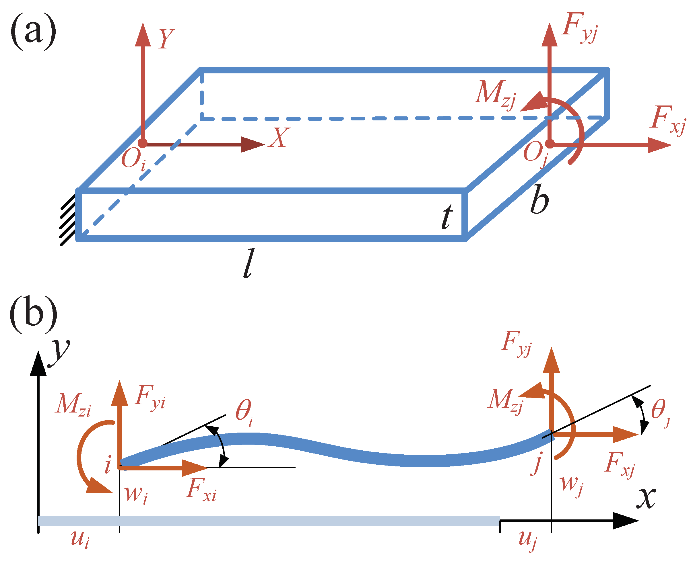
2.1. Beam Flexure’s Stiffness Matrix
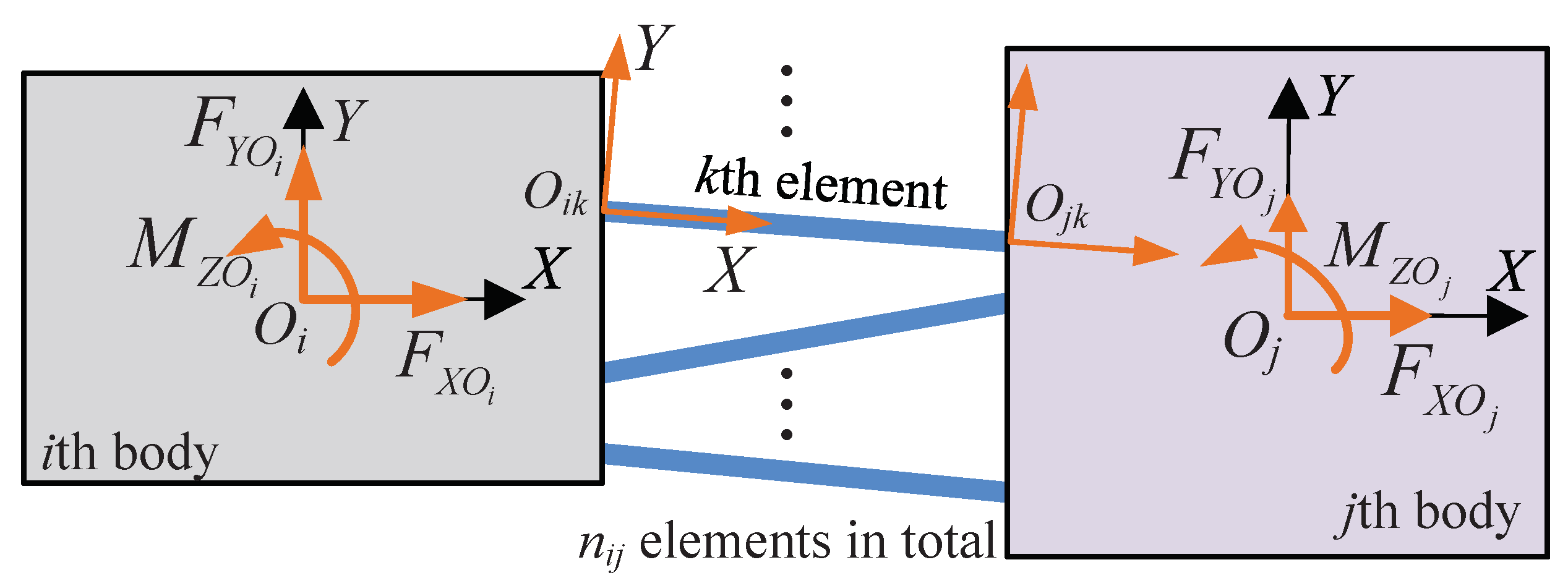
2.2. Stiffness Matrix of Two Bodies Connected by Flexures
2.3. Global Stiffness Matrix for Flexure Mechanism
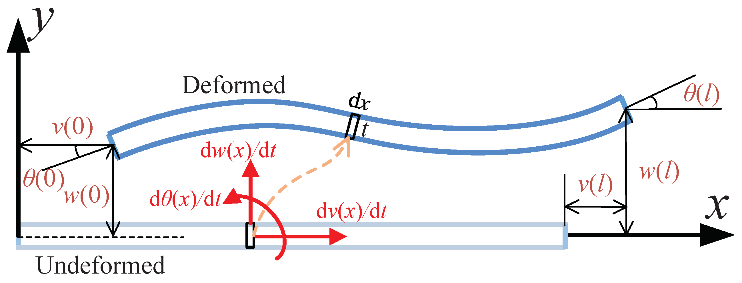
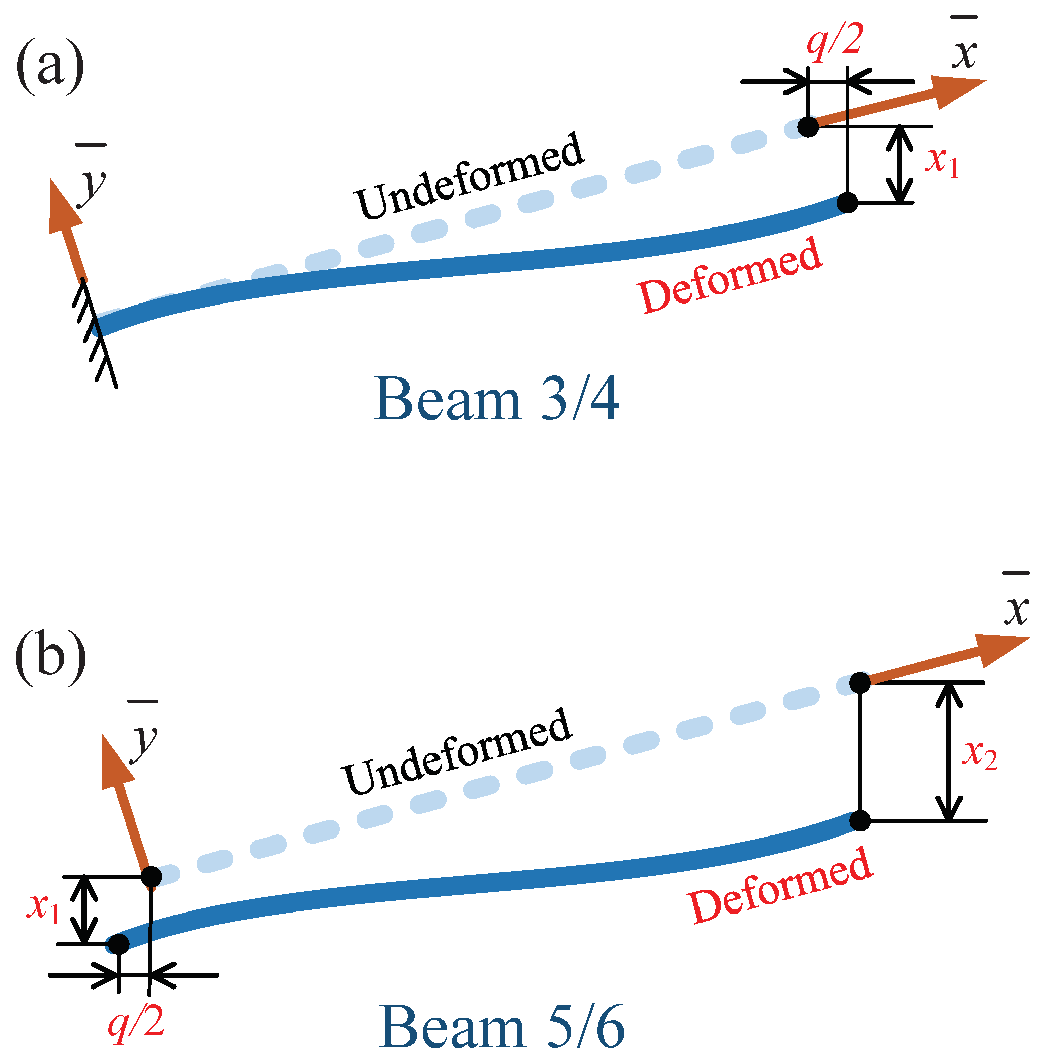
3. Improved Dynamic Model
4. Case Studies and Verification
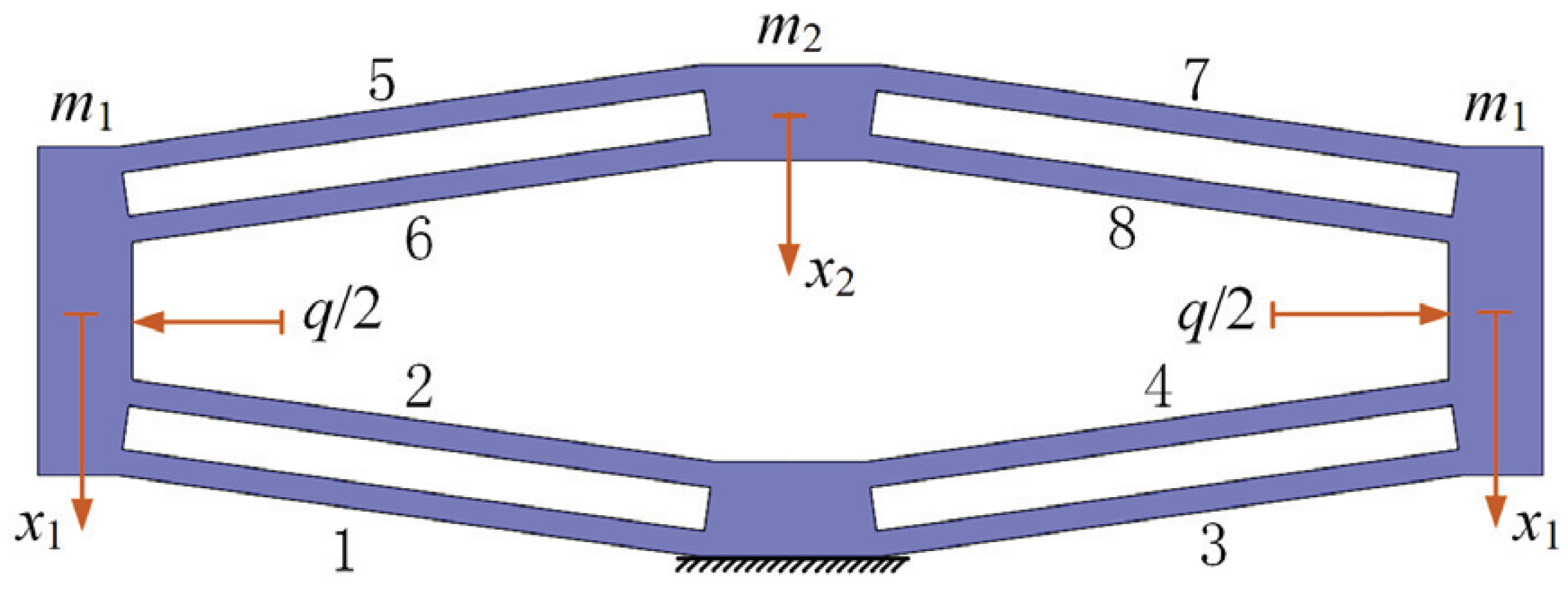
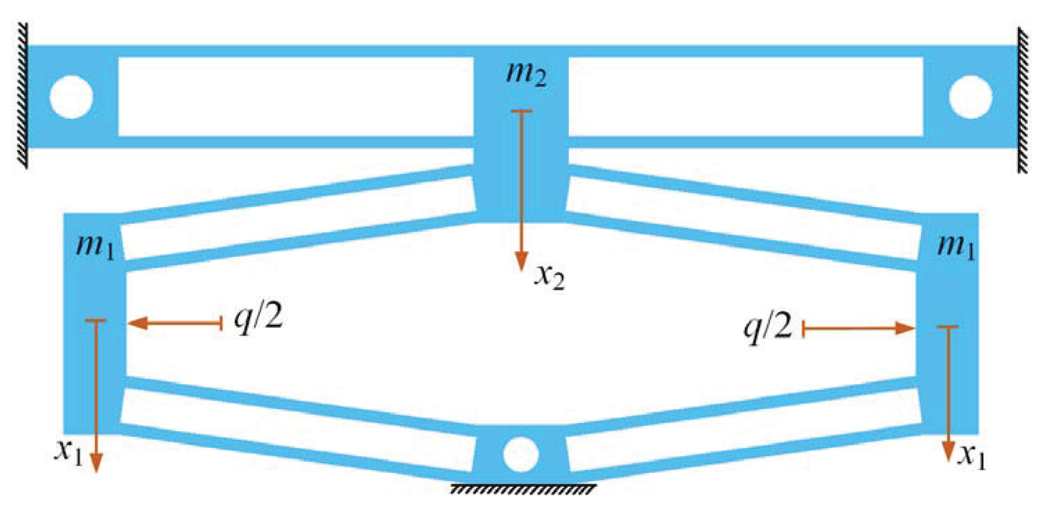
4.1. Compound Distributed-Compliance Bridge-Type Amplification Mechanism
4.2. Bridge-Type Mechanism Guided by Parallelogram Mechanism
5. Conclusions
Author Contributions
Funding
Conflicts of Interest
References
- Gu, G.Y.; Zhu, L.M.; Su, C.Y.; Ding, H.; Fatikow, S. Modeling and control of piezo-actuated nanopositioning stages: A survey. IEEE Trans. Autom. Sci. Eng. 2014, 13, 313–332. [Google Scholar] [CrossRef]
- Zhu, W.L.; Zhu, Z.; Shi, Y.; Wang, X.; Guan, K.; Ju, B.F. Design, modeling, analysis and testing of a novel piezo-actuated XY compliant mechanism for large workspace nano-positioning. Smart Mater. Struct. 2016, 25, 115033. [Google Scholar] [CrossRef]
- Yong, Y.K.; Aphale, S.S.; Moheimani, S.R. Design, identification, and control of a flexure-based XY stage for fast nanoscale positioning. IEEE Trans. Nanotechnol. 2008, 8, 46–54. [Google Scholar] [CrossRef]
- Choi, K.B.; Lee, J.J.; Hata, S. A piezo-driven compliant stage with double mechanical amplification mechanisms arranged in parallel. Sens. Actuators Phys. 2010, 161, 173–181. [Google Scholar] [CrossRef]
- Lai, L.J.; Zhu, Z.N. Design, modeling and testing of a novel flexure-based displacement amplification mechanism. Sens. Actuators Phys. 2017, 266, 122–129. [Google Scholar] [CrossRef]
- Chen, F.; Zhang, Q.; Gao, Y.; Dong, W. A review on the flexure-based displacement amplification mechanisms. IEEE Access 2020, 8, 205919–205937. [Google Scholar] [CrossRef]
- Chen, G.; Ma, Y.; Li, J. A tensural displacement amplifier employing elliptic-arc flexure hinges. Sens. Actuators Phys. 2016, 247, 307–315. [Google Scholar] [CrossRef]
- Liu, P.; Yan, P. A new model analysis approach for bridge-type amplifiers supporting nano-stage design. Mech. Mach. Theory 2016, 99, 176–188. [Google Scholar] [CrossRef]
- Qi, K.Q.; Xiang, Y.; Fang, C.; Zhang, Y.; Yu, C.S. Analysis of the displacement amplification ratio of bridge-type mechanism. Mech. Mach. Theory 2015, 87, 45–56. [Google Scholar] [CrossRef]
- Ling, M.; Wang, J.; Wu, M.; Cao, L.; Fu, B. Design and modeling of an improved bridge-type compliant mechanism with its application for hydraulic piezo-valves. Sens. Actuators Phys. 2021, 324, 112687. [Google Scholar] [CrossRef]
- Lobontiu, N.; Garcia, E. Analytical model of displacement amplification and stiffness optimization for a class of flexure-based compliant mechanisms. Comput. Struct. 2003, 81, 2797–2810. [Google Scholar] [CrossRef]
- Ma, H.W.; Yao, S.M.; Wang, L.Q.; Zhong, Z. Analysis of the displacement amplification ratio of bridge-type flexure hinge. Sens. Actuators Phys. 2006, 132, 730–736. [Google Scholar] [CrossRef]
- Xu, Q.; Li, Y. Analytical modeling, optimization and testing of a compound bridge-type compliant displacement amplifier. Mech. Mach. Theory 2011, 46, 183–200. [Google Scholar] [CrossRef]
- Liang, C.; Wang, F.; Huo, Z.; Shi, B.; Tian, Y.; Zhao, X.; Zhang, D. A 2-DOF Monolithic Compliant Rotation Platform Driven by Piezoelectric Actuators. IEEE Trans. Ind. Electron. 2020, 67, 6963–6974. [Google Scholar] [CrossRef]
- Chen, F.; Du, Z.j.; Yang, M.; Gao, F.; Dong, W.; Zhang, D. Design and analysis of a three-dimensional bridge-type mechanism based on the stiffness distribution. Precis. Eng. 2018, 51, 48–58. [Google Scholar] [CrossRef]
- Wu, H.; Lai, L.; Zhu, L. Analytical model and experimental verification of an elliptical bridge-type compliant displacement amplification mechanism. Rev. Sci. Instrum. 2021, 92, 055109. [Google Scholar] [CrossRef]
- Pan, B.; Zhao, H.; Zhao, C.; Zhang, P.; Hu, H. Nonlinear characteristics of compliant bridge-type displacement amplification mechanisms. Precis. Eng. 2019, 60, 246–256. [Google Scholar] [CrossRef]
- Choi, K.B.; Lee, J.J.; Kim, G.H.; Lim, H.J.; Kwon, S.G. Amplification ratio analysis of a bridge-type mechanical amplification mechanism based on a fully compliant model. Mech. Mach. Theory 2018, 121, 355–372. [Google Scholar] [CrossRef]
- Chen, J.; Zhang, C.; Xu, M.; Zi, Y.; Zhang, X. Rhombic micro-displacement amplifier for piezoelectric actuator and its linear and hybrid model. Mech. Syst. Signal Process. 2015, 50, 580–593. [Google Scholar] [CrossRef]
- Letty, R.L.; Claeyssen, F.; Lhermet, N.; Bouchilloux, P. New amplified piezoelectric actuator for precision positioning and active damping. In Proceedings of the SPIE 3041, Smart Structures and Materials 1997: Smart Structures and Integrated Systems, San Diego, CA, USA, 6 June 1997; pp. 496–504. [Google Scholar]
- Yin, L.; Ananthasuresh, G. Design of distributed compliant mechanisms. Mech. Based Des. Struct. Mach. 2003, 31, 151–179. [Google Scholar] [CrossRef]
- Sun, Y.; Liu, Y.; Pancheri, F.; Lueth, T.C. LARG: A Lightweight Robotic Gripper With 3-D Topology Optimized Adaptive Fingers. IEEE/ASME Trans. Mechatron. 2022, 27, 2026–2034. [Google Scholar] [CrossRef]
- Ling, M.; Zhang, X.; Cao, J. Extended dynamic stiffness model for analyzing flexure-hinge mechanisms with lumped compliance. J. Mech. Des. 2022, 144, 013304. [Google Scholar] [CrossRef]
- Wu, J.; Cai, S.; Cui, J.; Tan, J. A generalized analytical compliance model for cartwheel flexure hinges. Rev. Sci. Instrum. 2015, 86, 105003. [Google Scholar] [CrossRef] [PubMed]
- Liu, P.; Yan, P. Kinetostatic modeling of bridge-type amplifiers based on timoshenko beam constraint model. Int. J. Precis. Eng. Manuf. 2018, 19, 1339–1345. [Google Scholar] [CrossRef]
- Ding, Y.; Lai, L.J. Design and analysis of a displacement amplifier with high load capacity by combining bridge-type and Scott-Russell mechanisms. Rev. Sci. Instrum. 2019, 90, 065102. [Google Scholar] [CrossRef]


| Sample | Methods | Amplification Ratio | Input Stiffness () | 1st-Order Nat. Freq. (Hz) | Freq. Error (%) | |
|---|---|---|---|---|---|---|
| 1 | mm | Matrix | 6.31 | 19.35 | 855.13 | 50.37% |
| mm | FEA | 6.24 | 18.45 | 568.68 | / | |
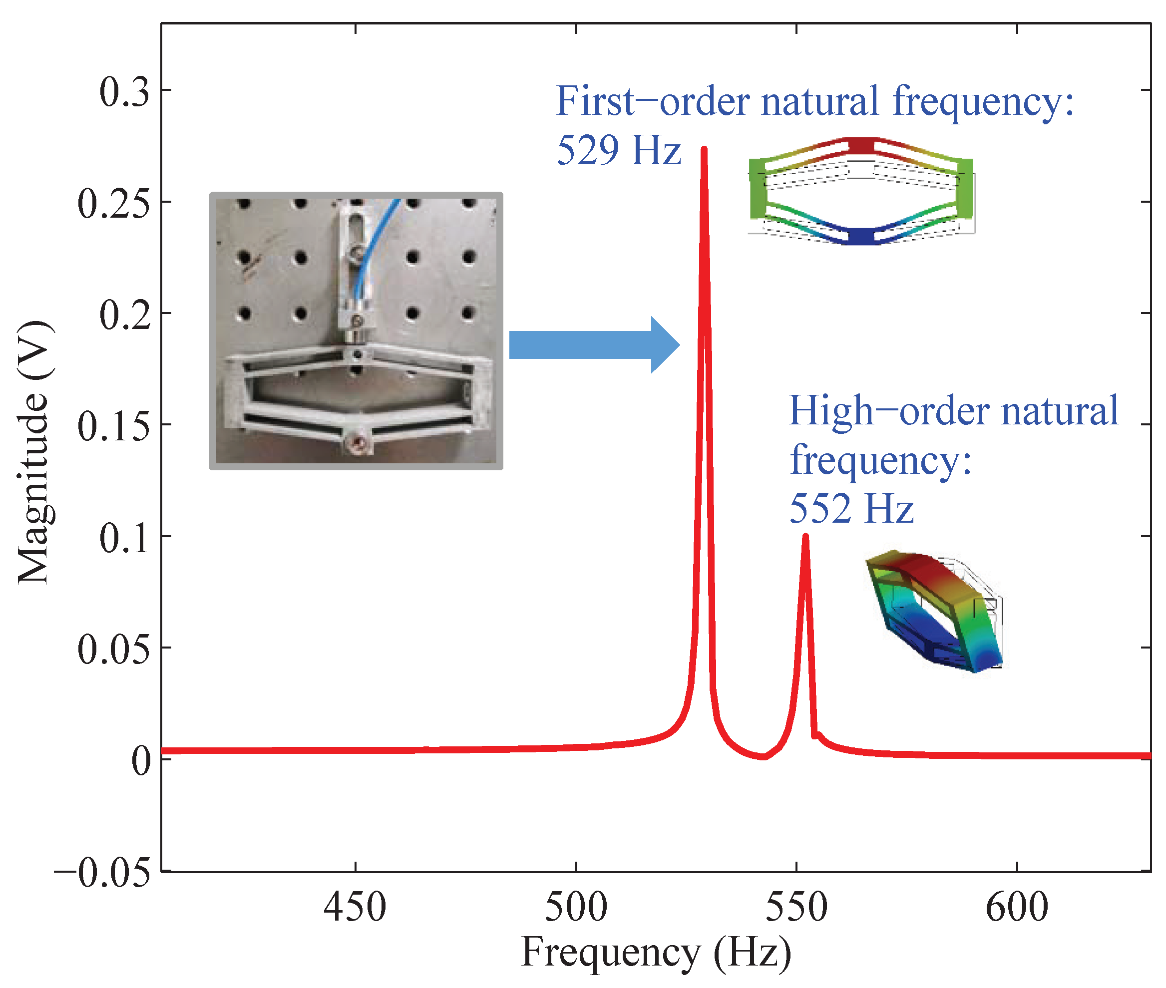
| mm | Test | 6.03 | 16.58 | 529 | / | |
| Imp. dyn. | / | / | 554.51 | 2.49% | ||
| 2 | mm | Matrix | 6.73 | 6.14 | 461.26 | 37.17% |
| mm | FEA | 6.24 | 5.95 | 326.27 | / | |
| mm | Test | 6.38 | 4.91 | 293.54 | / | |
| Imp. dyn. | / | / | 301.78 | 7.5% | ||
| 3 | mm | Matrix | 6.34 | 18.19 | 802.31 | 57.11% |
| mm | FEA | 6.28 | 17.28 | 510.64 | / | |
| mm | Test | 6.07 | 15.96 | 484 | / | |
| Imp. dyn. | / | / | 488.19 | 4.39% |
| Matrix Method | Improved Method | FEA | Test |
|---|---|---|---|
| (Hz) | (Hz) | (Hz) | (Hz) |
| 892.36 | 548.73 | 569.04 | 512 |
Publisher’s Note: MDPI stays neutral with regard to jurisdictional claims in published maps and institutional affiliations. |
© 2022 by the authors. Licensee MDPI, Basel, Switzerland. This article is an open access article distributed under the terms and conditions of the Creative Commons Attribution (CC BY) license (https://creativecommons.org/licenses/by/4.0/).
Share and Cite
Li, P.; Zhu, H.; Lai, L. An Improved Dynamic Model and Matrix Displacement Model for Distributed-Compliance Bridge-Type Amplification Mechanism. Actuators 2022, 11, 368. https://doi.org/10.3390/act11120368
Li P, Zhu H, Lai L. An Improved Dynamic Model and Matrix Displacement Model for Distributed-Compliance Bridge-Type Amplification Mechanism. Actuators. 2022; 11(12):368. https://doi.org/10.3390/act11120368
Chicago/Turabian StyleLi, Peixing, Helei Zhu, and Leijie Lai. 2022. "An Improved Dynamic Model and Matrix Displacement Model for Distributed-Compliance Bridge-Type Amplification Mechanism" Actuators 11, no. 12: 368. https://doi.org/10.3390/act11120368
APA StyleLi, P., Zhu, H., & Lai, L. (2022). An Improved Dynamic Model and Matrix Displacement Model for Distributed-Compliance Bridge-Type Amplification Mechanism. Actuators, 11(12), 368. https://doi.org/10.3390/act11120368