Abstract
The task of performing locomotion and manipulation simultaneously poses several scientific challenges, such as how to deal with the coupling effects between them and how to cope with unknown disturbances introduced by manipulation. This paper presents an inverse dynamics-based whole-body controller for a torque-controlled quadrupedal manipulator capable of performing locomotion while executing manipulation tasks. Unlike existing methods that deal with locomotion and manipulation separately, the proposed controller can handle them uniformly, which can take into account the coupling effects between the base, limbs and manipulated object. The controller tracks the desired task–space motion references based on a hierarchical optimization algorithm, given a set of hierarchies that define strict priorities and the importance of weighting each task within a hierarchy. The simulation results show the robot is able to follow multiple task–space motion reference trajectories with reasonable deviation, which proved the effectiveness of the proposed controller.
1. Introduction
In some dangerous environments, such as natural and man-made disasters, robots are more suitable than humans to execute tasks to protect emergency responders. Legged robots offer significant advantages over their wheeled or tracked counterparts, as these advantages assist in traversing challenging terrain and unstructured environments. To make these legged platforms more versatile and practical, equipping a legged robot with additional appendages, such as arms dedicated to manipulation tasks, expands the possibility of deploying them in the real world. A multi-limbed robotic system needs to make or break contact as well as modulate contact forces with its environment to move and balance its robot’s base (locomotion) and move the targeting object (manipulation). The governing dynamics in such complex robotic systems have a higher degree of freedom (DOF) and more complex hybrid transitions, making the design of controllers for such systems more challenging.
In the past few years, there has been a lot of progress in locomotion [1,2,3,4,5] and manipulation [6,7], but few solutions on the coordination of locomotion and manipulation are presented. Among these studies, the following works deserve attention. Some humanoid robots complete impressive locomotion and manipulation work [8,9] in the DARPA Robotics Challenge. However, the locomotion and manipulation tasks are not handled by the same controller, and the manipulation can only be performed when feet are planted and do not take any steps. The legged robot HyQ [10] equipped with a six-DOF arm HyArm performs a static walking gait while tracking motions of the arm. The presented controller integrates a mobile platform controller and a model-free arm controller combined with a payload estimation module. As a further study, a whole-body controller was developed for the quadrupedal robot HyQ equipped with a seven-DOF manipulator arm, which allows for the implementation of a Cartesian impedance control to coordinate tracking performance and desired compliance for the robot base and manipulator arm [11]. These two works show no demonstration of coordination between locomotion and manipulation. A hierarchical nonlinear control algorithm was developed, based on model predictive control, quadratic programming, and virtual constraints, to generate and stabilize motions [12]. Although some numerical simulation studies are presented to demonstrate the algorithm’s effectiveness, none of the manipulation tasks are achieved with the Kinova arm. Many impressive results have been achieved by Boston Dynamics’s robots BigDog [13], SpotMini and Spot. Robot Spot can simultaneously perform locomotion and manipulation tasks, e.g., opening and walking through a door with disturbances. However, no supplemental documentation illustrates methods and approaches that Boston Dynamics used to control these robots. The quadrupedal robot ANYmal [14] equipped with a six-DOF arm Jaco can perform dynamic locomotion while executing manipulation tasks, e.g., payload delivery, human-robot collaboration, and opening doors. Similar door opening scenarios have been achieved with a quadrupedal mobile manipulator, consisting of an ANYmal C platform equipped with a custom-made robotic arm [15]. Dynamic and kinematic consistent strategies are proposed to tackle the arising problems after equipping a quadruped robot with an arm [16]. The motion control of the arm is implemented separately; this decoupled control strategy is difficult to use to solve the problem of mutual interference between the arm and the base motions.
In order to fully explore the coupling effects between locomotion and manipulation, the dynamics of the entire system and the contact forces at all the robot’s limb end points need to be considered in the controller. This kind of controller, called whole-body controller (WBC), executes various tasks and accomplishes multiple control objectives. These controllers can be classified into inverse kinematics (IK)-based WBCs and inverse dynamics (ID)-based WBCs. The distinction between them is the output: IK-based WBCs produce joint velocities, while ID-based WBCs produce joint torques. Ultimately, the joint velocities/torques produced from both controllers are further transformed into motor currents with low-level impedance controllers or feedback torque controllers. Although those IK-based WBCs [7,17,18] are still used in robotic systems, the ID-based WBCs [19,20,21,22,23,24] are more suitable for torque-controlled robots. These controllers formulate the tracking problem within an optimization setting to resolve the task redundancy and incorporate equality and inequality constraints. An ID-based WBC has been used to control a legged manipulator [11], and it is formulated as a single quadratic program (QP) problem to find the ground reaction forces to track the desired Cartesian acceleration of task–space motion references. Although it can resolve the task redundancy via adjusting task weights, it is inevitable that tasks of higher importance will still be affected by tasks of lower importance. The hierarchical inverse dynamics approach proposed in [24] is extended for loco-manipulation in this work, for it can express complicated behaviours directly at the task level with strict enforcement of hierarchies between tasks. For example, it is useful to ensure that a balancing task of higher importance will take precedence over a motion tracking task of lower importance in case of conflicting goals.
This paper presents a whole-body controller, using hierarchical quadratic programming coupled with the full system dynamics, for a quadrupedal manipulator that creates adaptive behaviors and allows task–space and joint–space prioritized tasks to be executed. The controller tracks task–space motion references generated by a high-level planner described in [25]. The controller has been validated in simulation through a walking pivot task and a spring-loaded door opening task.
The remainder of the paper is structured as follows. The following section gives the full-body dynamics and its decomposition of the robotic system with floating-base. Section 3 presents the whole-body controller, formulating the control problem as a series of quadratic programs. Section 4 shows the simulation results of the proposed controller applied to the legged mobile manipulator Aliengo VX300 [26]. Finally, discussions and conclusions are given in Section 5.
2. Model Formulation
The model of a legged mobile manipulator can be formulated as a floating-base B to which limbs are attached. The position and orientation of the base frame with respect to the world frame are expressed as a three-dimensional vector and a Hamiltonian unit quaternion respectively. Limb joint positions are collected in the vector , where the number of joints is . The generalized coordinate vector and the generalized velocity vector are collected as
where number of velocity vectors is , and and are the linear and angular velocity of the floating-base with respect to the world frame expressed in the frame. The Aliengo VX300 robot shown in Figure 1 has DOFs, with six, twelve, and five DOFs describing the floating base, legs and the arm, respectively.
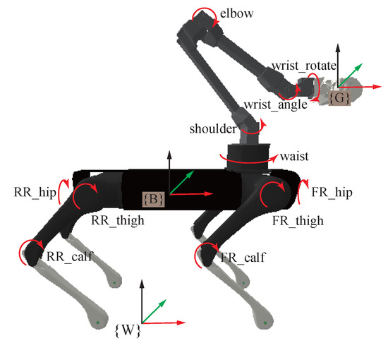
Figure 1.
Configuration of Aliengo VX300. The robot consists of an Aliengo quadrupedal robot created by the Unitree and a five-DOF ViperX 300 robotic arm from Trossen Robotics. Each leg has 3 joints called hip, thigh and calf joints. The arm has only 5 joints, namely, waist, shoulder, elbow, wrist_angle and wrist_rotate joints.
The equations of motion of a multi-limbed robot with a floating base can be written as
where stands for the inertia matrix, and is a vector of nonlinear terms (including Coriolis, centrifugal and gravity forces). The selection matrix represents the system under-actuation that the floating-base is not directly actuated by joint torques . If all limb joints are actuated, then the number of actuated joints . The vector of contact forces is mapped to the joint–space torques through the support Jacobian , which is obtained by stacking the end-effector Jacobians which relate generalized velocities to limb end motion as , with the number of limbs in contact.
For a robotic system with a floating base, its equations of motion Equation (2) can be decomposed as
where Equation (3) is the first six equations of Equation (2) related to the floating base and Equation (4) is the rest of the equations. The former equation can be interpreted as the Newton–Euler equations of the whole robotic system, expressing the relationship between the change of momentum of the system and external contact forces.
For the Aliengo VX300 robot, the contact forces in point-feet and gripper are both modelled as three-dimensional linear contact forces, and the open-source rigid body dynamics Library Pinocchio [27,28] is used to compute its robot dynamics. The dynamic model used in this paper is based on the CAD model of the robot, which means that it is not very accurate as it does not take into account the contribution of any type of friction in the model. A good parameter identification of the dynamics will certainly make better performance [29,30]. Actually, good results with ID-based WBC can still be obtained without a perfect dynamic model since this approach is robust to model uncertainty [24].
3. Whole-Body Control
The whole-body controller formulates tasks as affine functions of generalized accelerations and external generalized forces , and joint torques are then calculated from them. The control structure is depicted in Figure 2.
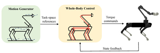
Figure 2.
Control Structure. Cartesian motion planner plans the task–space reference trajectories sent to the proposed controllers. The controllers track planned references while satisfying physical feasibility constraints.
Thanks to the decomposition Equations (3) and (4), the torques only occur in the actuated part and are linearly dependent on generalized accelerations and external forces in the form
Since all occurrences of the joint torques can be replaced with Equation (5), the decision variable can be chosen as
All robot tasks are often modelled in the form of one general task defined as a set of linear equality and/or inequality constraints on the decision variable :
where and are slack variables. They are not predefined but part of the optimization variables. For a specific task, the above equality constraint and inequality constraint may exist at the same time, or only one of them exists.
Here are the robot tasks used in the ID based WBC designed for the Aliengo VX300 robot to execute locomotion and manipulation tasks:
(1) Dynamic consistency: To ensure physical consistency, the underactuated part of the equations of motion (3) can be written in the general task form (7) with
which serves as a dynamic consistency equality constraint.
(2) Torque saturation limits: To ensure that the solution complies with the physical limitations, the joint torque limitation constraint can be formulated as
(3) Contact force limits: When the point feet are in contact with the ground, friction cone constraints on the resulting contact forces must be satisfied. The friction cone constraint means that the contact force of a single foot satisfies as follows:
The above constraint Equation (10) can be approximated by
All contact force constraints can be obtained by collecting the Equation (11) constraints of active contacts together as follows:
so the contact force limits constraint can be written as
(4) Contact motion task: Each contact introduces three constraint equations on its location , which can be differentiated twice to yield the following:
where is the corresponding support Jacobian. By stacking the above constraints for all active contacts together, the contact motion task can be formulated as
(5) Cartesian space acceleration task: For the base, gripper and lifted feet, the relationship between its velocity in Cartesian space and the generalized velocity is
which can be differentiated as
The deviation from the desired Cartesian acceleration can be penalized using
where and are diagonal positive definite matrices which define proportional and derivative gains, , and specified by a high-level motion planner or the operator; and are computed by forward kinematics based on the current robot state. Many tasks such as Base position control task, Base orientation control task, Gripper position control task, Gripper orientation control task and Swing foot position control task are specified with this form. It is worth noting that rotation-related operations should be handled based on requirements.
(6) Minimum motion task: To avoid internal drift, we can also introduce a joint–space task that spans the full configuration space of the robot. For example, we can penalize deviation from the nominal configuration with
where and are the nominal generalized positions and velocities of actuated joints, and and are vectors which define proportional and derivative gains. It is worth mentioning that these tasks are mostly taken at the lowest priority.
Table 1 lists the prioritized tasks designed for the quadrupedal manipulator to execute locomotion and manipulation tasks. In general, the hierarchy prioritizes the stability of the robot itself, then performing movements. The highest priority satisfies dynamic constraints and hardware limitations. The second priority task enforces kinematic contact constraints. The third priority tasks are used to track task–space motion and force references. Finally, the lowest priority task allows the robot to keep a better-looking posture.

Table 1.
Task hierarchy (0 is the highest priority).
A set of tasks with priorities can be solved in a strict prioritized way with a hierarchical optimization solver. To be specific, for the task with priority p, it is defined as:
The null space projector of this task is defined as:
Considering tasks , the augmented optional solution is
where and ; is solved from the optimization problem:
4. Simulation Studies
The simulation was conducted in PyBullet [31], a Python module for physics simulation, robotics and deep reinforcement learning based on the Bullet Physics software development kit (SDK). The dynamics library Pinocchio was employed to update robot dynamic terms such as inertia matrix and Jacobians. The open-source OSQP solver [32] and its C++ wrapper OSQP-Eigen was used to solve all the QPs in the proposed controller running at 500 Hz.
4.1. Walking Pivot
The walking pivot simulation experiment tests the whole-body controller by commanding the gripper to stay at a fixed position in the world frame. At the same time, the legged robot walks around the gripper, as shown in Figure 3. In detail, the robot stands in place (0∼1 s), steps back from the initial position (1∼3 s), crouches down (3∼4 s) and stands up (4∼5 s), rotates 360 degrees around a fixed point (5∼21 s), walks forward to the initial position (21∼23 s) and then stands still.
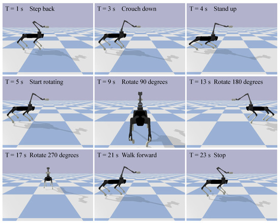
Figure 3.
Snapshots of the robot performing walking pivot motion.
The translation and rotation variation of the base are shown in Figure 4 and Figure 5, respectively. The base position was able to follow the reference with less than 0.01 m deviation in x and y direction. From the graph, there is a 0.03 m deviation from the reference in z direction. The reason is that during the crouches down movement, the task of keeping the gripper position has the same weight as the movement of the base. Therefore, the base sacrifices vertical movement to maintain gripper height. The base orientation reference can be followed well with less than 0.015 rad deviation in roll angle and 0.003 rad in pitch angle. The rotation around a fixed point was divided into four steps to test the ability of acceleration and deceleration of the proposed method. Therefore, from Figure 5, the angular velocity in the yaw direction oscillated four times and was reflected in the orientation trajectory.
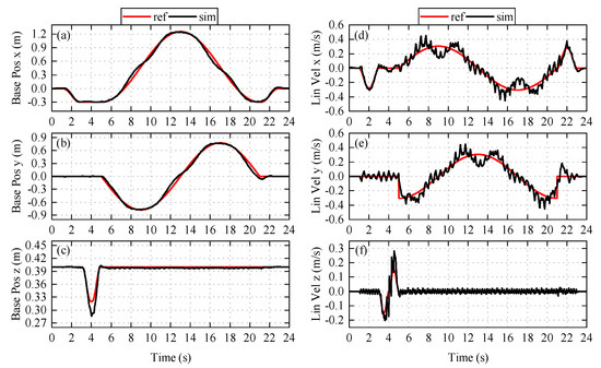
Figure 4.
Base position and linear velocity. Graphs (a–c) are position tracking in the x-, y-, and z-direction. Graphs (d–f) are linear velocity tracking and these velocities are expressed in the world frame.
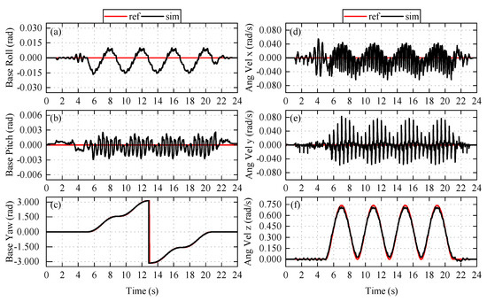
Figure 5.
Base orientation and angular velocity. Graphs (a–c) are orientation tracking in the x-, y-, and z-direction. Graphs (d–f) are angular velocity tracking and these velocities are expressed in the base frame.
The translation and rotation variation of the gripper are shown in Figure 6 and Figure 7, respectively. From Figure 6, the maximum deviation in x, y and z directions is 0.05 m. the Gripper position control task has the same weight with the Base position control task; thus, the results share similar characteristics with the results of the base. On the other hand, due to a lower weight in gripper orientation and the design of the arm, the gripper’s angular velocity in the yaw direction has larger deviation than base. A top-down view can have a more straightforward demonstration of the data mentioned above, as shown in Figure 8.
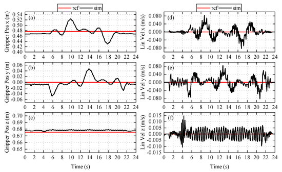
Figure 6.
Gripper position and linear velocity. Graphs (a–c) are position tracking in the x-, y-, and z-direction. Graphs (d–f) are linear velocity tracking and these velocities are expressed in the world frame.
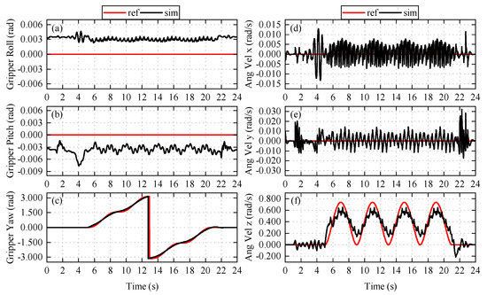
Figure 7.
Gripper orientation and angular velocity. Graphs (a–c) are orientation tracking in the x-, y-, and z-direction. Graphs (d–f) are angular velocity tracking and these velocities are expressed in the gripper frame.
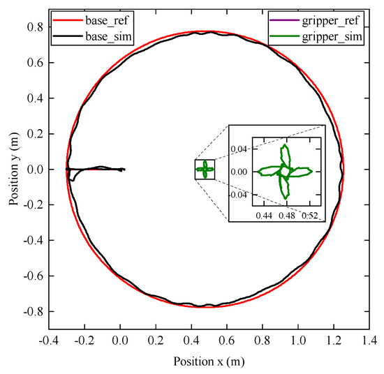
Figure 8.
Comparison between planned trajectories and actual trajectories. The large circle represents the base trajectory, and the center of the circle represents the gripper trajectory. The red and black lines represent the offline planned base reference and actual trajectories, respectively. The purple and green lines represent the planned and actual gripper trajectories.
4.2. Spring-Loaded Door Opening
To illustrate the ability of the whole-body controller to perform locomotion and manipulation tasks simultaneously in real-world missions, we demonstrate the execution of opening a spring-loaded door while performing a trotting gait. As shown in Figure 9, the door opening task can be broken down into the following processes: approach the door (1∼5 s), locate the door handle (5∼7 s), open the gripper (7∼7.5 s), approach the handle (7.5∼8 s), clamp on to the handle (8∼8.5 s), turn the handle (8.5∼10.5 s), gently push the door open (10.5∼12.5 s), reposition the handle (12.5∼13 s), hold the door while walking pass (13∼18 s), rotate the base while keeping the gripper position fixed (18∼21 s) and finally reverse to release the spring-loaded door (21∼25 s).
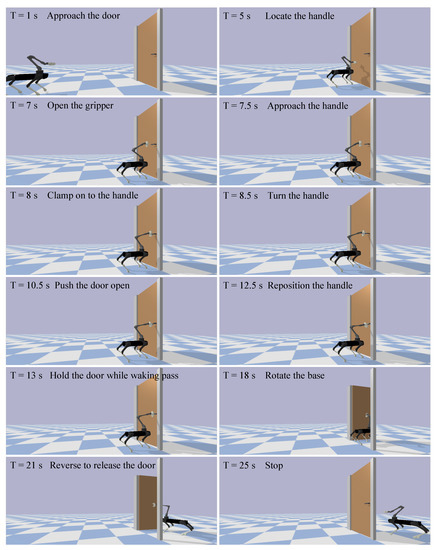
Figure 9.
Snapshots of the robot opening a spring-loaded door.
Figure 10 shows the top view of the position and orientation trajectories of the base, gripper and door during the door opening task. As can be seen from the picture, with unknown forces from the spring-loaded door acting on the gripper, the robot can still finish the complex door opening task.
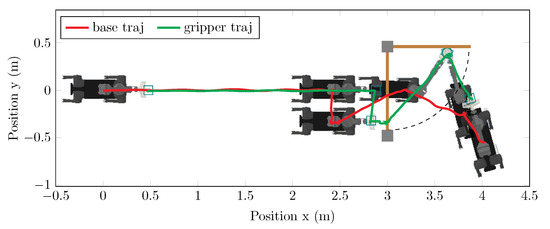
Figure 10.
Top view of base and gripper trajectories during opening and walking through a spring-loaded door. The red line represents the robot base trajectory, the green line indicates the gripper trajectory, and the brown line denotes the door position.
Figure 11 shows the base velocity and base height. The maximum velocity deviation of 0.06 m/s appears in y direction around 3 s, and the maximum height deviation of 0.015 m appears near 20 s due to a higher weight in the Base position control task. The developed whole-body controller prioritizes all robot tasks, which is beneficial for tracking reference after keeping balance.
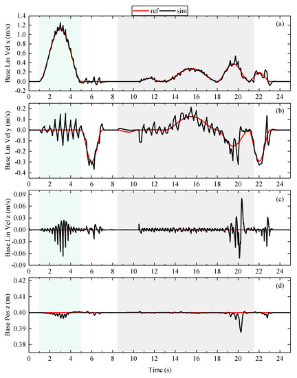
Figure 11.
The time evolution of the base linear velocity and base height. Graphs (a–c) are the linear velocity tracking in the x-, y- and z-direction, and these velocities are expressed in the world frame. Graph (d) is the base height tracking. The green area indicates the process of approaching the door. The gray area indicates the time duration of manipulating the door.
Figure 12 shows the desired torques of arm joints generated by the whole-body controller during the door opening process. The elbow joint fluctuates intensively from 1 s to 5 s due to shoulder and elbow joints parallel to each other and having more than one kinematic solution for a gripper pose relative to the base. In addition, the base velocity contributes to the fluctuation. It can also be seen from the graphic that the joint torques of the arms change considerably to open the door when the robotic arm interacts with the spring-loaded door.
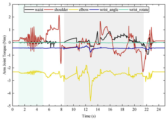
Figure 12.
The time evolution of the commanded torques of arm joints generated by the whole-body controller. The gray area indicates the time duration of manipulating the door.
Figure 13 shows the torque of each joint of the door. It should be noted that, in simulation, a joint controller was added to each joint of the door to function as a door closing device and handle spring. It can be seen from these two graphics that when the robot starts to interact with the door, the joint torques of the arm have significant increase. This change indicates that the whole-body controller adjusts the desired torque value to balance the unknown external force and ensure that the reference base pose and gripper pose can be tracked. At the same time, the door moves passively, and resistance torque is generated in the corresponding joint of the door.
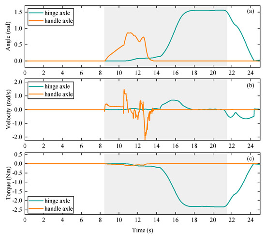
Figure 13.
Positions, velocities and resistance torques of door joints. Graphs (a–c) are joint angle, velocity and torque. The gray area indicates the time duration of opening the door.
Figure 14 presents the force acting from the ground to the feet in the world frame. Since the robot is walking in trot gait, the force acting on the front left foot is similar to the rear right foot, and the front right foot is similar to the rear left foot. Therefore, we only choose one pair to show the result. During the process of approaching the door, the force in the x direction reflects the acceleration and deceleration of the robot in the same direction. The force in the y direction exists to balance the robot and keep a straight walking trajectory. The force generated by interacting with the door is relatively small compared to the force created by the trotting motion, and can be distinguished in the graph. The maximum force in the z direction when the robot trots is twice the maximum force when it stands still. This is because the robot lifts diagonal legs simultaneously at a higher speed, and only two legs make contact with the ground when it trots.
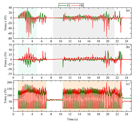
Figure 14.
Ground reaction forces of the front-left and front-right feet. Graphs (a–c) are contact forces in x-, y- and z-direction, and these forces are expressed in the world frame. The green area indicates the process of approaching the door. The gray area indicates the time duration of opening the spring-loaded door. The orange area indicates the robot is trotting.
5. Conclusions
A whole-body controller is implemented which uses a hierarchical inverse dynamics approach considering the dynamics of the whole robotic system, enabling a torque-controlled quadrupedal manipulator capable of performing locomotion and manipulation tasks simultaneously. Unlike existing methods that separate the whole control problem into locomotion and manipulation sub-problems, the controller can uniformly balance locomotion and manipulation, which makes it possible to account for the coupling effects between the base, limbs and object. In addition, we found that the controller enables the robot to passively respond external disturbances and complete the tracking task even in the absence of an accurate root dynamics model and the dynamic properties of the manipulated object are unknown. The above advantages are very beneficial to deploy legged manipulators in unstructured and uncertain environments to complete tasks. The effectiveness of the controller was thoroughly demonstrated in two specially designed cases based on real-life scenarios, which include walking and manipulating objects.
The current robot arm has only five joints, with two of them parallel to each other, which limits the movement of the gripper in space. Further study will employ a better arm to improve the system performance. Future work will also focus on developing a whole-body motion planner that plans whole-body motion and force trajectories tracked by the controller for tasks combining dynamic locomotion and manipulation.
Author Contributions
Conceptualization, J.L. and C.Z.; Data curation, J.L.; formal analysis, J.L.; funding acquisition, J.L., H.G., H.Y. and C.Z.; investigation, J.L., J.H. and C.Z.; methodology, J.L.; project administration, C.Z.; resources, H.G., H.Y. and C.Z.; software, J.L.; supervision, H.G., H.Y. and C.Z.; validation, J.L. and C.P.; visualization, J.L. and Y.W.; writing—original draft, J.L.; writing—review and editing, J.L., Y.W., J.H., C.P. and C.Z. All authors have read and agreed to the published version of the manuscript.
Funding
This work was supported by the Engineering and Physical Sciences Research Council [grant numbers EP/R513258/1-2441459, EP/V026801/2], the Advanced Machinery and Productivity Institute [Innovate UK project number 84646] and the China Scholarship Council [grant number (2020)06120186].
Institutional Review Board Statement
Not applicable.
Informed Consent Statement
Not applicable.
Data Availability Statement
Not applicable.
Acknowledgments
We would like to thank Songyan Xin for discussions on hierarchical inverse dynamics approach based whole-body controllers.
Conflicts of Interest
The authors declare no conflict of interest.
Abbreviations
The following abbreviations are used in this manuscript:
| DOF | Degree of freedom |
| WBC | Whole body controller |
| IK | Inverse kinematics |
| ID | Inverse dynamics |
| QP | Quadratic Program |
| HQP | Hierarchical quadratic programming |
| SDK | Software development kit |
References
- Carlo, J.D.; Wensing, P.M.; Katz, B.; Bledt, G.; Kim, S. Dynamic Locomotion in the MIT Cheetah 3 Through Convex Model-Predictive Control. In Proceedings of the IEEE/RSJ International Conference on Intelligent Robots and Systems, Madrid, Spain, 1–5 October 2018; pp. 1–9. [Google Scholar]
- Kim, D.; Carballo, D.; Di Carlo, J.; Katz, B.; Bledt, G.; Lim, B.; Kim, S. Vision Aided Dynamic Exploration of Unstructured Terrain with a Small-Scale Quadruped Robot. In Proceedings of the IEEE International Conference on Robotics and Automation, Paris, France, 31 May–31 August 2020; pp. 2464–2470. [Google Scholar]
- Luo, B. Balance control based on six-dimensional spatial mechanics and velocity adjustment through region intervention and foot landing for quadruped robot. Robotica 2022, 40, 855–2877. [Google Scholar] [CrossRef]
- Biswal, P.; Mohanty, P. Modeling and Effective Foot Force Distribution for the Legs of a Quadruped Robot. Robotica 2021, 39, 1504–1517. [Google Scholar] [CrossRef]
- Zhornyak, L.; Emami, M. Gait Optimization for Quadruped Rovers. Robotica 2020, 38, 1263–1287. [Google Scholar] [CrossRef]
- Lv, N.; Liu, J.; Jia, Y. Dynamic Modeling and Control of Deformable Linear Objects for Single-Arm and Dual-Arm Robot Manipulations. IEEE Trans. Robot. 2022, 38, 2341–2353. [Google Scholar] [CrossRef]
- Xing, H.; Liang, D.; Gao, H.; Li, W.; Tavakoli, M. Dual-User Haptic Teleoperation of Complementary Motions of a Redundant Wheeled Mobile Manipulator. IEEE Trans. Syst. Man Cybern. Syst. 2022, 52, 6283–6295. [Google Scholar] [CrossRef]
- Feng, S.; Whitman, E.; Xinjilefu, X.; Atkeson, C.G. Optimization-Based Full Body Control for the DARPA Robotics Challenge. J. Field Robot. 2015, 32, 293–312. [Google Scholar] [CrossRef]
- Kuindersma, S.; Deits, R.; Fallon, M.; Valenzuela, A.; Dai, H.; Permenter, F.; Koolen, T.; Marion, P.; Tedrake, R. Optimization-Based Locomotion Planning, Estimation, and Control Design for the Atlas Humanoid Robot. Auton. Robot. 2016, 40, 429–455. [Google Scholar] [CrossRef]
- Rehman, B.U.; Focchi, M.; Lee, J.; Dallali, H.; Caldwell, D.G.; Semini, C. Towards a multi-legged mobile manipulator. In Proceedings of the IEEE International Conference on Robotics and Automation, Stockholm, Sweden, 16–21 May 2016; pp. 3618–3624. [Google Scholar]
- Risiglione, M.; Barasuol, V.; Caldwell, D.G.; Semini, C. A Whole-Body Controller Based on a Simplified Template for Rendering Impedances in Quadruped Manipulators. In Proceedings of the IEEE/RSJ International Conference on Intelligent Robots and Systems, Kyoto, Japan, 23–27 October 2022; pp. 1–8. [Google Scholar]
- Hamed, K.A.; Kim, J.; Pandala, A. Quadrupedal Locomotion via Event-Based Predictive Control and QP-Based Virtual Constraints. IEEE Robot. Autom. Lett. 2020, 5, 4463–4470. [Google Scholar] [CrossRef]
- Abe, Y.; Stephens, B.; Murphy, M.P.; Rizzi, A.A. Dynamic whole-body robotic manipulation. In Proceedings of the Unmanned Systems Technology XV, Baltimore, MD, USA, 17 May 2013; pp. 3618–3624. [Google Scholar]
- Bellicoso, C.D.; Krämer, K.; Stäuble, M.; Sako, D.; Jenelten, F.; Bjelonic, M.; Hutter, M. ALMA-Articulated Locomotion and Manipulation for a Torque-Controllable Robot. In Proceedings of the IEEE International Conference on Robotics and Automation, Montreal, QC, Canada, 20–24 May 2019; pp. 8477–8483. [Google Scholar]
- Sleiman, J.P.; Farshidian, F.; Minniti, M.V.; Hutter, M. A Unified MPC Framework for Whole-Body Dynamic Locomotion and Manipulation. IEEE Robot. Autom. Lett. 2021, 6, 4688–4695. [Google Scholar] [CrossRef]
- Xin, G.; Zeng, F.; Qin, K. Loco-Manipulation Control for Arm-Mounted Quadruped Robots: Dynamic and Kinematic Strategies. Machines 2022, 10, 719. [Google Scholar] [CrossRef]
- Zhou, C.; Fang, C.; Wang, X.; Li, Z.; Tsagarakis, N. A generic optimization-based framework for reactive collision avoidance in bipedal locomotion. In Proceedings of the IEEE International Conference on Automation Science and Engineering, Fort Worth, TX, USA, 21–24 August 2016; pp. 1026–1033. [Google Scholar]
- Humphreys, J.; Peers, C.; Li, J.; Wan, Y.; Sun, J.; Richardson, R.; Zhou, C. Teleoperating a Legged Manipulator through Whole-Body Control. In Proceedings of the 23rd Annual Conference Towards Autonomous Robotic Systems, Oxford, UK, 1 September 2022; pp. 63–77. [Google Scholar]
- Kim, D.; Carlo, J.D.; Katz, B.; Bledt, G.; Kim, S. Highly dynamic quadruped locomotion via whole-body impulse control and model predictive control. arXiv 2019, arXiv:1909.06586. [Google Scholar]
- Feng, S.; Whitman, E.; Xinjilefu, X.; Atkeson, C.G. Optimization Based Full Body Control for the Atlas Robot. In Proceedings of the IEEE-RAS International Conference on Humanoid Robots, Madrid, Spain, 18–20 November 2014; pp. 120–127. [Google Scholar]
- You, Y.; Xin, S.; Zhou, C.; Tsagarakis, N. Straight leg walking strategy for torque-controlled humanoid robots. In Proceedings of the IEEE International Conference on Robotics and Biomimetics, Qingdao, China, 3–7 December 2016; pp. 2014–2019. [Google Scholar]
- Bellicoso, C.D.; Gehring, C.; Hwangbo, J.H.; Fankhauser, P.; Hutter, M. Perception-less Terrain Adaptation through Whole Body Control and Hierarchical Optimization. In Proceedings of the IEEE-RAS International Conference on Humanoid Robots, Cancun, Mexico, 15–17 November 2016; pp. 558–564. [Google Scholar]
- Kuindersma, S.; Permenter, F.; Tedrake, R. An efficiently solvable quadratic program for stabilizing dynamic locomotion. In Proceedings of the IEEE International Conference on Robotics and Automation, Hong Kong, China, 31 May–7 June 2014; pp. 2589–2594. [Google Scholar]
- Herzog, A.; Rotella, N.; Mason, S.; Grimminger, F.; Schaal, S.; Righetti, L. Momentum control with hierarchical inverse dynamics on a torque-controlled humanoid. Auton. Robot. 2016, 40, 473–491. [Google Scholar] [CrossRef]
- Li, J.; Peers, C.; Xin, S.; Zhou, C. Opening a Spring-Loaded Door with a Legged Manipulator. In Proceedings of the 5th UK Robotics and Autonomous Systems Conference, Aberystwyth, UK, 26 August 2022; pp. 1–2. [Google Scholar]
- Peers, C.; Motawei, M.; Richardson, R.; Zhou, C. Development of a Teleoperative Quadrupedal Manipulator. In Proceedings of the 4th UK-RAS Conference, Hatfield, UK, 2 June 2021; pp. 17–18. [Google Scholar]
- Carpentier, J.; Saurel, G.; Buondonno, G.; Mirabel, J.; Lamiraux, F.; Stasse, O.; Mansard, N. The Pinocchio C++ library: A fast and flexible implementation of rigid body dynamics algorithms and their analytical derivatives. In Proceedings of the IEEE/SICE International Symposium on System Integration, Paris, France, 14–16 January 2019; pp. 614–619. [Google Scholar]
- Carpentier, J.; Valenza, F.; Mansard, N. Pinocchio: Fast forward and Inverse Dynamics for Poly-Articulated Systems. 2015–2019. Available online: https://stack-of-tasks.github.io/pinocchio (accessed on 1 September 2022).
- Ayusawa, K.; Venture, G.; Nakamura, Y. Identifiability and identification of inertial parameters using the underactuated base-link dynamics for legged multibody systems. Int. J. Robot. Res. 2014, 33, 446–468. [Google Scholar] [CrossRef]
- Chang, X.; An, H.; Ma, H. Modeling and base parameters identification of legged robots. Robotica 2022, 40, 747–761. [Google Scholar] [CrossRef]
- Coumans, E.; Bai, Y. Pybullet, a Python Module for Physics Simulation for Games, Robotics and Machine Learning. 2016. Available online: https://pybullet.org/wordpress/ (accessed on 1 September 2022).
- Stellato, B.; Banjac, G.; Goulart, P.; Bemporad, A.; Boyd, S. OSQP: An operator splitting solver for quadratic programs. Math. Program. Comput. 2020, 12, 637–672. [Google Scholar] [CrossRef]


Publisher’s Note: MDPI stays neutral with regard to jurisdictional claims in published maps and institutional affiliations. |
© 2022 by the authors. Licensee MDPI, Basel, Switzerland. This article is an open access article distributed under the terms and conditions of the Creative Commons Attribution (CC BY) license (https://creativecommons.org/licenses/by/4.0/).