Article

Effects of Flexural Rigidity on Soft Actuators via Adhering to Large Cylinders

1
College of Mechanical and Electrical Engineering, Nanjing University of Aeronautics and Astronautics, Nanjing 210016, China
2
Nanjing University of Aeronautics and Astronautics Shenzhen Research Institute, Shenzhen 518063, China
*
Author to whom correspondence should be addressed.
These authors contributed equally to this work.
Actuators 2022, 11(10), 286; https://doi.org/10.3390/act11100286
Submission received: 12 September 2022 / Revised: 28 September 2022 / Accepted: 1 October 2022 / Published: 7 October 2022
(This article belongs to the Special Issue Soft Actuators and Robotics)

Abstract

:
This study proposes a soft pneumatic actuator with adhesion (SPAA) consisting of a top fluidic-driven elastic actuator and four bottom adhesive pads for adhering to large cylinders. Finite element models were developed to investigate the bending properties under positive air pressure and the effect of “rib” height on the flexural rigidity of the SPAA. A synchronous testing platform for the adhesive contact state and mechanics was developed, and the bending curvature and flexural rigidity of the SPAA were experimentally measured relative to the pressure and “rib” height, respectively, including the adhesion performance of the SPAA with different rigidities on large cylinders. The obtained results indicate that the SPAA can continuously bend with controllable curvature under positive air pressure and can actively envelop a wide range of cylinders of different curvatures. The increase in the “rib” height from 4 to 8 mm increases the flexural rigidity of the SPAA by approximately 230%, contributing to an average increase of 54% in the adhesion performance of the SPAA adhering to large cylinders. The adhesion performance increases more significantly with an increase in the flexural rigidity at a smaller peeling angle. SPAA has a better adhesion performance on large cylinders than most existing soft adhesive actuators, implying that is more stable and less affected by the curvature of cylinders. To address the low contact ratio of the SPAA during adhesion, the optimization designs of the rigid–flexible coupling hierarchical and differentiated AP structures were proposed to increase the contact ratio to more than 80% in the simulation. In conclusion, this study improved the adhesion performance of soft adhesive actuators on large cylinders and extended the application scope of adhesion technology. SPAA is a basic adhesive unit with a universal structure and large aspect ratio similar to that of the human finger. According to working conditions requirements, SPAAs can be assembled to a multi-finger flexible adhesive gripper with excellent maneuverability.

1. Introduction

Gripping large smooth cylinders is challenging for robotic grippers [1,2]. Conventional grippers use normal and frictional forces to grip objects. If an object is relatively smaller than the gripper, the gripper can envelop the object to form a shape closure that holds it; however, when the object is relatively larger than the gripper, the gripper squeezes the surface of the object to generate frictional forces and grips to lift the object while relying on the resultant force of normal squeezing and tangential frictional forces. In this case, the component force of each squeezing force is vertically downward, and this tends to push the object away from the gripper. As the object becomes larger, the gripper needs to open wider to fit it, and this increases the resultant downward force (sum of the downward component force of each squeezing force). When the downward resultant force exceeds the upward lifting force, the gripper is unable to grip the object [3]. Therefore, interfacial adhesion technologies, such as vacuum adsorption, electrostatic adhesion, and gecko-like dry adhesion, which can generate interfacial attraction without excessive squeezing, have been employed in grippers [2]. Vacuum adsorption can provide a significant lifting force on non-porous objects; however, it is unsuitable for low-pressure and underwater environments [4]. Electrostatic adhesion can produce active adhesion on smooth and rough surfaces; however, it has a limited performance on non-metallic objects and requires additional control infrastructure to provide kV level high voltages [5]. Gecko-like dry adhesions rely on the van der Waals force generated by the close contact between the gecko-inspired micro-structured surface and the target to maintain adhesion. Moreover, various adhesive grippers have been developed for different applications.
According to the working conditions requirements, the adhesive gripper is assembled using several adhesive actuators; therefore, the mechanical properties of an adhesive actuator directly determine the operating performance of the gripper. For instance, rigid grippers assembled using two or three rigid planar adhesive actuators [6,7,8,9] exhibit excellent gripping performance on flat objects (PCB boards, glass sheets, and silicon wafers) but are not suitable for curved objects (cylinders); while soft grippers assembled using tendon-driven under-actuated adhesive actuators [5,10,11,12] or fluid-driven elastic actuators [13,14] exhibit excellent performance in gripping cylinders. However, the lifting capacity of soft adhesive grippers when adhering to cylinders decreases obviously with an increase in the radius of the cylinder. For adhering to large cylinders, the structural rigidity evidently affects the performance of the adhesive actuator/unit [4,15]. Although the inherent compliance of soft adhesive actuators can increase their adaptability to a wide range of targets of different sizes, they also reduce their structure rigidity, which is essential for maintaining adhesion, thereby reducing the peak adhesion performance [16,17]. By embedding photoresistant materials with a high elastic module into an elastic adhesive unit, the adhesion force can be enhanced [18]. In addition, the rigid–flexible adhesive unit can generate a larger area of adhesion during loading than a single flexible adhesive unit, resulting in a higher normal adhesion force and the ratio of adhesion force to preload [19]. As to the fluidic–elastic actuator, it has different flexural rigidity at different positions along its axial direction [13]. Moreover, the effective length of the fluidic–elastic actuator significantly affects the lifting force of the gripper [20], indicating that the structural stiffness of the actuator can be optimized to improve the performance of the gripper on objects with different curvatures. In general, the dependence of the adhesion on the structural parameters of the soft actuator is a crucial issue. The rigidity of the soft adhesive actuator/unit not only determines the acting mechanism of the actuator on the underlying adhesion system, but also affects the adhesion properties of the actuator adhering to the targets. Therefore, to adhere to large cylinders, it is essential to explore the effect of structural rigidity on the adhesion property of the soft actuator, which is helpful in guiding the mechanical design and rigidity optimization of the soft adhesive actuator to improve the adhesion performance on large cylinders.
This study proposes a soft pneumatic actuator with adhesion (SPAA) that combines a fluidic-driven elastic actuator with a mushroom-shaped microstructured adhesive surface for adhering to large cylinders. The effect of the flexural rigidity of the SPAA when it adheres to large cylinders is investigated. Section 2 presents the design of SPAAs with different bending rigidities and establishes finite-element models (FEMs) to predict their bending and rigidity properties. Section 3 describes the fabrication of the SPAAs and establishment of the experimental platform. Section 4 experimentally evaluates the performance of SPAAs with different bending rigidities when adhering to large cylinders. Section 5 compares SPAAs with existing adhesive actuators and proposes structural optimization schemes to solve the challenge of insufficient contact through finite element analysis (FEA). Section 6 provides a brief conclusion and potential areas for future studies.

2. Design and FEMs of the SPAA

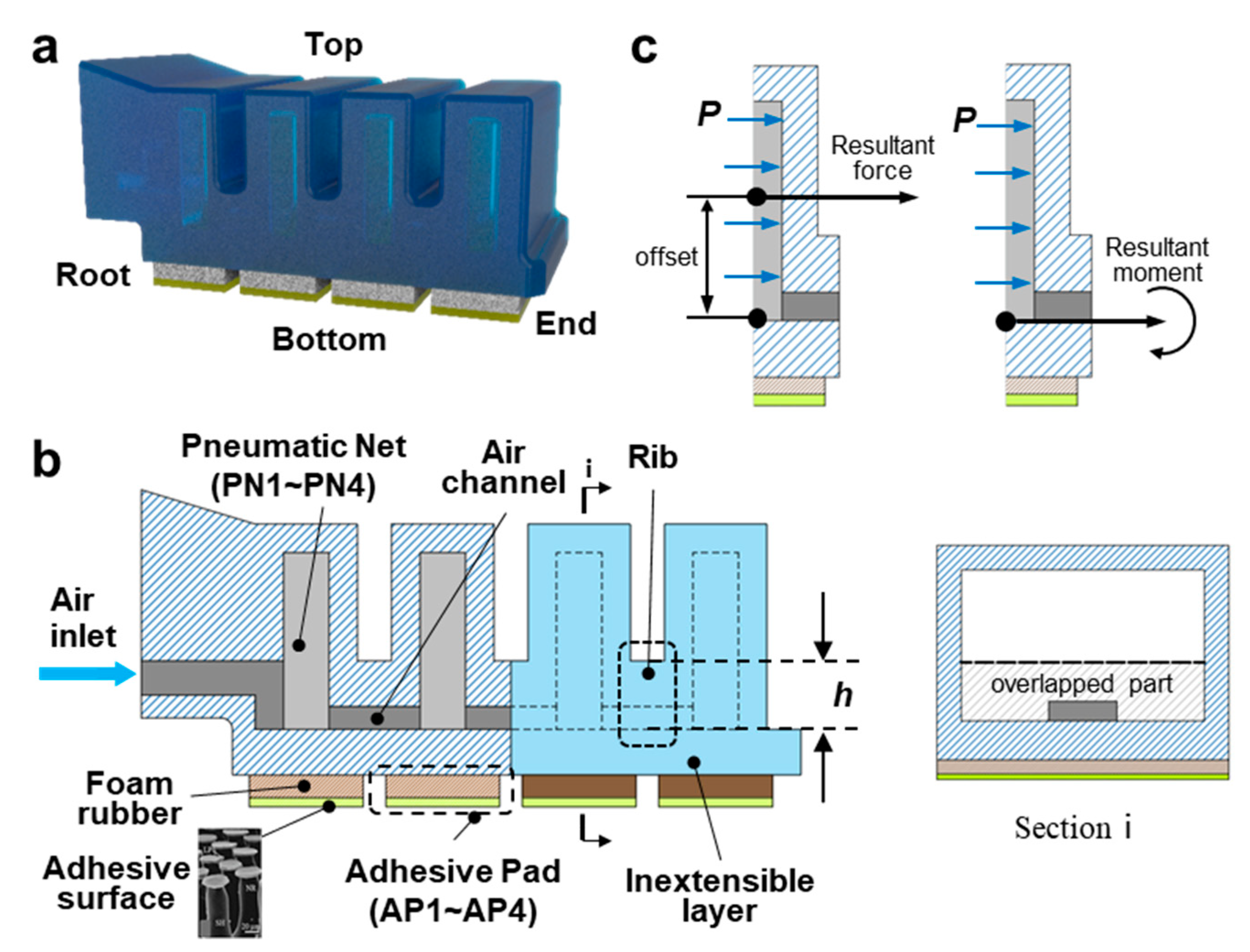
2.1. Design of the SPAA

The SPAA (Figure 1a) consists of a top fluidic-driven elastic actuator and four bottom adhesive pads (Figure 1b). Specifically, the elastic actuator comprises four pneumatic networks [21,22] (PN, numbered PN1~PN4 from the root to end) connected through the inside air channel and an inextensible but flexible layer. As shown in Figure 1c, when a pressure P applies to the inner side wall of the PN, the resultant force acts on the geometric center of the side wall. Due to the offset between the resultant force and the inextensible layer, each PN is subjected to a resultant moment, causing the SPAA to bend to the bottom. Each PN has a length of 30 mm, a width of 9 mm, a height of 18 mm, and a thickness of 3 mm. Four adhesive pads (AP, numbered AP1~AP4 from the root to the end) are equidistantly bonded on the bottom of the SPAA. Each AP consists of the foamed rubber and a mushroom-shaped microstructured dry adhesive surface [23] with a length of 30 mm, a width of 10 mm, and a thickness of 3 mm. The SPAA has a total length of 48 mm under no deformation.
In order to study the effect of the flexural rigidity (EI) of the SPAA when it adheres to large cylinders, we aimed to obtain a series of SPAAs with significant differences in EI by changing the geometric parameters of the “rib” (the connection part between two PNs (Figure 1b)). The reference [21] proposed that the larger the rib width, the lower the EI, but the effect is not apparent. In this study, the SPAA would generate a slight forced-reverse bending when adhering to a cylinder, while the pressure on the inner sidewall of PNs resists this forced bending. In particular, the resistance directly acts on the overlapped part of the inner sidewall (section I in Figure 1b) and the rib, so we assumed that the area of this overlapped part has a significant effect on the EI of the SPAA. Finally, we designed three SPAAs with the rib height h of 4 mm, 6 mm, and 8 mm, and the rest of the geometric parameters were the same.

2.2. FEMs of the Bending Curvature and Flexural Rigidity

To predict the bending curvature and flexural rigidity of the SPAA under positive pressure, FEMs were established and analyzed using Abaqus/Standard (SIMULIA, Dassault System, Providence, RI, USA). The hyper-elastic Mooney–Rivlin model [20,24] (C10 = 0.4138, C01 = 0.1034, d = 2) and the Arruda–Boyce model [25] (μ = 0.5788, λm = 1.2099) were used to characterize the top elastic actuator and the bottom foam rubber, respectively.
Figure 2a shows the FEM of the bending curvature of the SPAA. The end of the SPAA was fixed, and a positive air pressure P (varying from 0 to 100 kPa at 10 kPa intervals) was uniformly applied to the inner wall. In order to accurately describe the bending state of the SPAA, we used C1~C4 to characterize the bending curvature of PN1~PN4, respectively. We divided the abdomen of the SPAA into four equal parts with five yellow markers (numbered marker0~marker4 from the root to the end), recorded the simulation results of the five markers’ coordinates under the SPAA’s bending state, and obtained C1~C4 according to C = α/l Where α and l, respectively, represent the central angle and length of the arc that each PN bends into under positive pressure. Specifically, α can be obtained by geometric calculation based on the recorded data of markers’ coordinates (the angles between the connecting line of Marker0 and Marker1~Marker4 and the vertical direction were numbered as θ1~θ4, respectively, then α1~α4 were 2θ1, 2(θ2θ1), 2(θ3θ2), 2(θ4θ3), respectively). And l = 12 mm. The simulation results of four PNs’ bending curvatures under the pressures varying from 0 to 100 kPa at 10 kPa intervals (Figure 2b) show that C1~C4 all increase with an increase in the air pressure, and the relationships are approximately linear ( R C 1 2 = 0.9974 ,   R C 2 2 = 0.9978 ,   R C 3 2 = 0.9963 ,   R C 4 2 = 0.9970 ). However, C1 is obviously lower than C2~C4. It is because one side of PN1 is directly fixed to the root, thus limiting the bending of the PN1. As for PN2~PN4, the bending curvature is similar. Therefore, we used the mean value of the C2~C4 to define the bending curvature C of the SPAA. The simulation results of bending curvatures of three SPAAs with different rib heights under pressures varying from 0 to 100 kPa at 10 kPa intervals (Figure 2c) show that bending curvatures of SPAAs are positively correlated with the pressure, and the relationships are approximately linear ( R h = 4 2 = 0.9957 ,   R h = 6 2 = 0.9980 ,   R h = 8 2 = 0.9996 ). The results indicate that the SPAA can continuously bend with controllable bending curvature under positive air pressures.
Figure 2d shows the FEM of the flexural rigidity of the SPAA. Based on the bending curvature model in Figure 2a, we applied a normal force F = 0.6 N to the end of the deformed SPAA, recorded the simulation results of the five markers’ coordinates, and calculated the change of curvature ΔC of the SPAA before and after the action. According to reference [21], we defined the flexural rigidity E I = F d / Δ C to represent the ability of the SPAA to resist the bending deformation, where d represents the distance from the root of SPAA to the force F. The simulation results of flexural rigidity of three SPAAs with different rib heights under pressures varying from 0 to 100 kPa at 10 kPa intervals (Figure 2e) show that the flexural rigidity is almost unaffected by the pressure, but is significantly affected by the height of rib. When the height of the rib increases from 4 to 8 mm, the mean value of the flexural rigidity increases from 6440 to 14,090 N·mm2, an increase of 120%, which is much higher than the 10% increase in the flexural rigidity generated by decreasing the width of the rib from 3 to 0.8 mm [21]. The results indicate that it is theoretically reasonable to significantly increase the flexural rigidity of the SPAA by increasing the height of the rib.

3. Experimental Setup for Characterizing the Performance of the SPAA

3.1. Fabrication of the SPAA

The top elastic actuator was integrally formed by flexible 3D printing using SLA technology, which is simpler and more efficient than conditional pouring processing methods. The machine used is Form3 (Formlabs, Boston, MA, USA). The material used is flexible resin elastic 50 A with an elastic modulus of 2.89 MPa and a hardness of 50A after curing [26]. The foam rubbers were equidistantly attached to the bottom of the actuator using a 3M tape, and the dry adhesive surfaces [23] were attached to the foam rubbers. Three SPAA samples with rib heights of 4, 6, and 8 mm are shown in Figure 3d.

3.2. Setup of the Synchronous Testing Platform

The synchronous testing platform of adhesive contact state and mechanics, as shown in Figure 3a, was built to evaluate the deformation, rigidity, and adhesion-peeling performance of the SPAA on large cylinders. The SPAA was fixed on a two-axis mobile platform that can move at any angle within 0~100 mm/s in the plane through a rigid cantilever beam. A six-dimensional force sensor (NBIT, Nanjing, China) was installed between the SPAA and the cantilever beam to record the force value during the SPAA adhering to cylinders. The force sensor has a force range of ±100 N, a moment range of ±5 N·m, and a resolution of 0.10% F·S. A manual pressure regulator (ZKAY, WuXi, China) that can continuously adjust the pressure in the range of 0~0.2 MPa was series connected in the gas circuit to adjust the driving pressure. In order to avoid the pressure pulsation caused by the sudden change of pressure, a lower pressure regulation speed was adopted. The digital indicator showed the internal pressure value of the SPAA in real-time with a resolution of 1 kPa (Figure 3b). The smooth and light-transmitting acrylic cylinder with LED light strips illuminating the edges (Figure 3c). According to the principle of frustrated total reflection [27], the area where the SPAA contacts the cylinder generated a facula with a significantly higher brightness than the non-contact area, which is convenient for extracting the contact area by computer graphics processing. The large cylinders with a radius of approximately two (R = 100 mm), three (R = 150 mm), and four times (R = 200 mm) of the length of the SPAA were selected for SPAAs to adhere to. Markers were drawn with a highlighter on one side of the SPAA in order to extract the coordinate information of Markers through computer graphics processing to calculate the bending curvature of the SPAA. Two high-speed cameras were placed on the front and side of the platform, respectively. The front recorded the bending and contact states of the SPAA, and the side recorded the distribution of the contact area.

4. Results

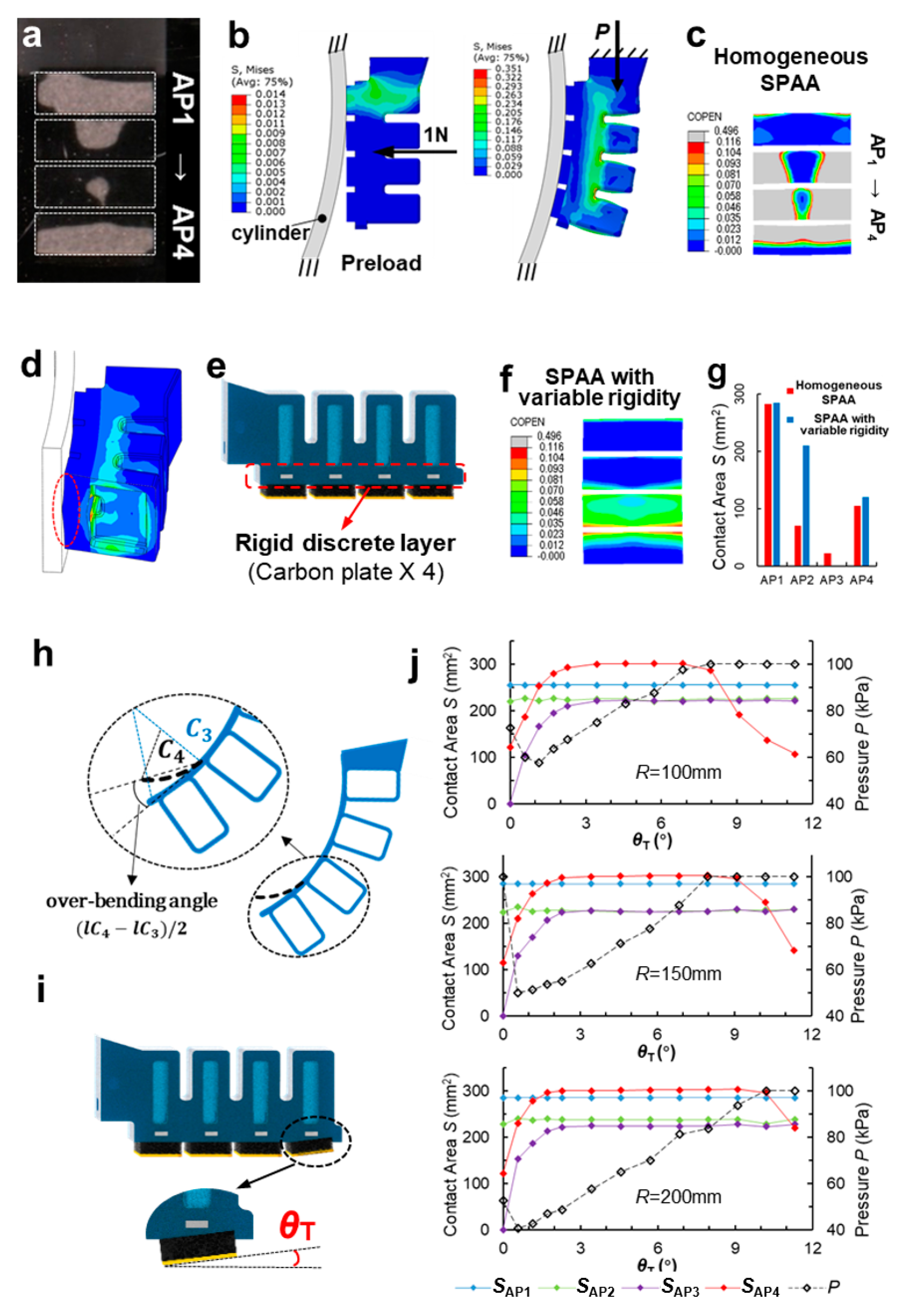
4.1. Bending Curvature and Flexural Rigidity

Figure 4a shows the bending state of three SPAAs with rib heights of 4, 6, and 8 mm at 0, 50, and 100 kPa, respectively. With the increase in pressure, three SPAAs all bend toward the bottom, and the curvature increases. Figure 4b shows the experimental results of the bending curvature of three SPAAs at pressures varying from 0 to 100 kPa at 10 kPa intervals. It is obvious that the bending curvatures of three SPAAs are positively correlated with the pressure, and the relationships are approximately linear ( R h = 4 2 = 0.9953 ,   R h = 6 2 = 0.9982 ,   R h = 8 2 = 0.9995 ). When P = 100 kPa, with an increase in the rib height, the bending curvatures of three SPAAs reach 25.4, 21.2, and 16.5 m−1, respectively. It can be verified that the SPAA can continuously bend under positive air pressure drive and the bending curvature is controllable. Compared to the rigid [9,28] or under-actuated [10] soft actuators, SPAAs can actively envelop a wide range of cylinders with different curvatures. The simulation results in Figure 2c deviate within 7% of the experimental results.
Figure 4c shows the test flow of SPAA’s flexural rigidity, which is similar to the FEM in Figure 2d. Figure 4d shows the experimental results of the flexural rigidity of three SPAAs under pressures varying from 0 to 100 kPa at 10 kPa intervals. The rigidity increases when the rib height increases but remains almost constant when the pressure increases. As the rib height goes up from 4 to 8 mm, the flexural rigidity of the SPAA increases from 6125 to 13,300 N·mm2, an increase of 117%, demonstrating that it is more reasonable to significantly increase the flexural rigidity of the SPAA by increasing the rib height than decreasing the rib width [21]. The above experimental and FEM results in Figure 2 have the same trend with a high degree of agreement, and the deviations are all within 10%. Therefore, the FEMs in Section 2.2 can predict the mechanical properties of SPAA.

4.2. Contact State and Mechanical Properties

Figure 5a presents the flow of the adhesion-peeling performance test of the SPAA. (1) Approach: the SPAA approaches the cylinder fixed vertically at 0.15 mm/s horizontally. (2) Preload: AP1 comes in contact with the cylinder while the SPAA approaches. When the preload reaches 1 N, the SPAA stops moving. (3) Adhesion: the SPAA contacts and adheres to the cylinder gently as the air pressure increases slowly. (4) Peeling: the SPAA peels off from the cylinder at a speed of 0.15 mm/s with release angles θ p of 90°, 60°, and 30°. (5) Separate: the SPAA stops moving until it separates from the cylinder completely. The left pictures of the five stages are the images captured by the side camera. The four white dotted boxes from top to bottom are the areas of AP1~AP4. The bright spots in dotted boxes represent the contact areas (based on the principle of frustrated total reflection in Section 3.2). The right pictures are the images captured by the front camera.
The bending state, contact area, and adhesion force of the SPAA were recorded simultaneously during the whole test. Figure 5b shows a typical curve of tangential adhesion force (Ft), normal adhesion force (Fn) of the SPAA, and contact areas of four APs (SAP1~SAP4) versus the time. During the preload, only AP1 contacts the cylinder and generates a normal squeezing force of approximately 1 N. During the adhesion, AP2, AP3, and AP4 are in contact with the arc surface orderly as the air pressure increases. Meantime, the SPAA exerts a small tangential adhesion force to the cylinder away from the root. It is mainly because the inextensible layer of the SPAA inevitably generates a slight tensile deformation during the expansion of the SPAA. During the peeling, the SPAA does not peel off the cylinder once, but generates two peeling processes. In the first peeling, the Ft and Fn go up and SAP1~SAP3 go down synchronously. When the Ft and Fn reach the peak, they fall back rapidly, SAP1~SAP3 drop to zero at the same time. In the second peeling, the Ft and Fn increase again but at a slower rate, together with the slight decrease in the SAP4. When the Ft and Fn reach the peak, Ft, Fn, and SAP4 drop to zero at the same time.

4.3. Adhesion-Peeling Performance on Large Cylinders

Figure 6 presents the experimental results of the contact area of four APs (SAP1~SAP4) during the adhesion stage. Obviously, the SAP4 increases the most with an increase in the rib height. As the rib height increases from 4 to 8 mm, the contact ratio of the end region increases from 40% to 70%, indicating that a higher rib of the SPAA benefits a more sufficient contact. A low standard deviation means that the contact area state of each AP is little affected by the curvature of the cylinder. We also found that AP3 has the lowest contact area with a 15% contact ratio, indicating that the adhesion performance of the area near AP3 is also lower than that of other APs.
Figure 7 presents the peak forces of Ft and Fn in the first and second peelings of three SPAAs with different rib heights, and defined as Ft_peak1, Fn_peak1, Ft_peak2, and Fn_peak2, respectively (Figure 5b). It is evident that with the rib height of the SPAA increasing, the peak adhesive forces show an upward trend. As the rib height increases from 4 mm to 8 mm, the forces Fn_peak1 and Fn_peak2 stabilize in the range of 7~10 N and 2~6 N, respectively, and increase slowly. The tangential adhesion force also increases with the rib height increasing, but it is significantly affected by the peeling angle θp. Specifically, the force Ft_peak2 at θp = 30° increases from 6 N to 10~12 N, the most evident increase. The above results mean that the increase in the rib height is conducive to a more outstanding adhesion performance of the SPAA on large cylinders, and the effect is more significant when at a smaller peeling angle. Further, the average increases of Fn_peak1, Ft_peak1, Fn_peak2, and Ft_peak2 are 20%, 31%, 102%, and 62%, respectively. The increase in the peak adhesion forces in the second peeling is 2~5 times that in the first peeling. Since the Ft_peak2 and Fn_peak2 are generated by the peeling off of the AP4 (Section 4.2), it can be verified that the increase in the rib height can significantly improve the adhesion performance of the SPAA’s end contact region.
The influence of peeling angle θp on the peak tangential adhesion force is more significant than that of the peak normal adhesion force. As the θp decreases from 90° to 30°, Ft_peak1 increases from 2~4 N to 8~12 N, with an average increase of 290%; the Ft_peak2 increases from approximately 4 N to 6~12 N, with an average increase of 95%; while the increase in peak normal adhesion force is very small, only 2%. When peeling at 90°, the Ft_peak1 is only approximately 10%~30% of the Fn_peak1, and the Ft_peak2 is equivalent to the Fn_peak2. However, when peeling at 30°, Ft_peak1 is basically the same as the Fn_peak1, and the Ft_peak2 is 2~3 times of the Fn_peak2. In general, the decrease in θp is beneficial to a more excellent tangential adhesion performance of the SPAA on large cylinders, and the effect is more significant when the SPAA has a larger flexural rigidity. In addition, SPAAs with different bending rigidities show a very stable normal adhesion performance when peeling at different angles on large cylinders. Cylinder curvature has little effect on the adhesion performance of the SPAA. As the curvature decreases, the overall adhesion force decreases slightly, indicating that the SPAA can generate a stable adhesion performance when adhering to cylinders with large curvatures.

5. Discussion

The SPAA consists of a top fluidic-driven elastic actuator and four bottom adhesive pads attached with mushroom-shaped microstructured adhesive surfaces. The results of the bending curvature test verify that its controllable and the SPAA can continuously bend under positive air pressure. In comparison with rigid [9,28] or under-actuated [10] soft actuators, the SPAA can actively envelop a wide range of cylinders with different curvatures. Moreover, novel actuating methods such as electrostatic–hydraulic coupled [29,30], chemical reacting [31], magnetic field [32] and biohybrid system actuations [33] have been applied to soft actuators/robots, enabling them to be more flexible, robust and programmable. Combining bio-inspired adhesion with novel actuators is a promising research direction. The flexural rigidity results demonstrate that increasing the rib height can significantly increase the flexural rigidity of SPAA. In comparison to the 10% slight increase in flexural rigidity obtained by reducing the rib weight from 3 to 0.8 mm [21], increasing the rib height from 4 to 8 mm can increase the flexural rigidity of the SPAA by approximately 230%. The results of the adhesion–peeling performance tests indicate that an increase in the rib height and decrease in the peeling angle are conducive to a more outstanding adhesion performance of the SPAA on large cylinders.

5.1. Comparison between the SPAA and Other Adhesive Units

Table 1 shows the adhesion capacity of the existing adhesive grippers consisting of soft adhesive actuators. These grippers are all parallel structures that rely on two opposed adhesive actuators to envelop and lift the target. The lifting capacity of the gripper is a combination of two actuators’ adhesion capacities. In addition, the two adhesive actuators are mechanically fixed and assembled into an adhesive gripper, so there is a distance between the two actuators. This distance results in an angle between the tangential direction of the actuator and the vertical lifting direction, which is the peeling angle defined in Section 4.2. Furthermore, when the curvature of the gripped surface is constant, the greater the distance, the smaller the peeling angle. Given the significant influence of the peeling angle on the performance of the adhesive actuator (Section 4.3), Table 1 also considers the peeling angle of the adhesive actuator into consideration.
By comparison, the structural dimensions of adhesive actuators in Table 1 are all in the order of 10 to 100 mm, which are similar to the dimension of SPAA. Most performance tests of the grippers focus on adhering to curved surfaces with a radius of less than 100 mm, and the lifting capacity of grippers decreases as the radius of the curved surface increases, which is similar to the SPAA (except for the gripper in the reference [5], where the adhesion actuator is long, and an increase in the radius of the curved surface increases the adhesion contact area, thereby increasing the adhesive lifting force). Nevertheless, the mean values of two peak normal adhesion forces when the SPAA with a rib height of 8 mm peeling off from a cylinder with a radius equal to 100 mm at a peeling angle of 90° are 9.8 N and 5.4 N, respectively. Both of these two normal adhesion forces of a single SPAA approach or even exceed the lifting force (the combination of two actuators’ adhesion forces) of adhesive grippers summarized in Table 1 (except for the grippers in the references [13]). In particular, when the gripper in the reference [13] adheres to a cylinder with a radius of 75 mm, the combined adhesive lifting force of its two adhesive actuators reaches 18 N, which is 1.5~4 times the adhesion performance of a single SPAA. This is mainly because the radius of the gripped cylinder and the peeling angle of the gripper’s two actuators are all smaller than those of the SPAA (As mentioned in Section 4.3, a small radius of the cylinder or peeling angle contributes to an excellent adhesion performance). When the SPAA with a rib height of 8 mm adheres to the cylinder with a 100 mm radius and peels off at 60°, the resultant adhesion force reaches 11.8 N. It can be predicted that when two SPAAs are integrated into a parallel gripper to grip a cylinder with a 75 mm radius, their performance will reach or even exceed 18 N. The gripper in the reference [5] achieves an adhesive lifting force of 12 N when adhering to the cylinder with a 150 mm radius, which is slightly higher than the peak resultant adhesion force of 10.3 N in the first peeling and 9.2 N in the second peeling of the SPAA with an 8 mm rib height when adhering to the cylinder with a 150 mm radius and peeling off at 60°, due to the fact that the adhesive actuator of the gripper in the reference [5] has twice the size of the SPAA. However, when evaluated in terms of the adhesion strength (adhesive force per unit area), the normal adhesion strength of the SPAA is approximately three times greater than that of the adhesive actuator of the gripper in the reference [5].
In summary, most of the existing adhesive grippers are used for gripping curved surfaces with a radius of less than 100 mm. The adhesive lifting performance decreases obviously with the radius increase. However, the SPAA shows excellent adhesion performance when adhering to large cylinders, and the normal adhesion performance is little affected by changes in the radius. The magnitude and stability of the SPAA’s adhesion performance are better than that of the soft adhesive grippers summarized in Table 1.

5.2. Optimization for High Contact Ratio

Figure 6 shows that the contact ratio between AP2 and AP3 is less than 30%, and Figure 8a shows that the contact area between AP2 and AP3 is mainly in the middle when SPAA contacts the curved surface. It is obvious that the adhesion performance of the region near AP2 and AP3 is not fully utilized.
To investigate the cause of this defect, a FEM (Figure 8b) that describes the contact state of the SPAA was established, where the cylinder was fixed on the bottom side of the PSAA, and the adhesive behavior of the interfacial contact was described by the cohesive model [24,36]. In the preload stage, the PSAA approached and contacted the cylinder at a speed of 0.15 mm/s until the interfacial contact force reached 1 N. In the adhesion stage, the SPAA bent and enveloped the cylinder as the pressure P was applied to the inner wall of SPAA. The simulation results of the contact areas of four Aps (Figure 8c) agree well with the experimental results (Figure 8a). The simulated cross-section of the SPAA in contact with the cylinder is shown in Figure 8d. Obviously, when the SPAA is driven by positive pressure, the inextensible layer also passively expands from its initial plane into an arc, driving Aps to bend radially into an arc. As a result, only small raised areas in the middle of Aps are in contact with the cylinder, although the SPAA has enveloped the cylinder well. We have exploited the inherent flexibility of soft materials to enable better envelope adaptation of the SPAA than conventional rigid actuators, but have neglected that flexibility also reduces the rigidity of the SPAA’s bottom side, which affects the contact adaptation. Studies on bio-adhesive systems have shown that a hierarchical structure with variable rigidity facilitates an adequate fit of the gecko toe to the surface [37]. Studies on biomimetic soft adhesive actuators have improved contact adaptation by adjusting the rigidity of the dorsal muscles [13]. In conclusion, the hierarchical structure with rigid–flexible coupled rigidity is beneficial in improving the contact adaptation of the SPAA without affecting its bending performance.
To solve the inadequate contact of the SPAA, we should increase the radial flexural rigidity of the inextensible layer by an order of magnitude without affecting the layer’s axial flexural rigidity. Here, we propose a solution of embedding a rigid discrete layer inside the inextensible layer of the SPAA. It is important that the rigid discrete layer should have a high elastic module to resist the bending deformation of the inextensible layer and a low density to minimize the effect of the local mass difference on the performance of the SPAA. Carbon plates have an elastic module of approximately 240 GPa and a density of approximately 1.8 g/cm3. Compared to ordinary steel, such as aluminum alloy, carbon plates are lighter in weight and higher in bending strength. Finally, four carbon plates (3 mm * 1.5 mm * 30 mm) were selected and embedded inside the inextensible layer (Figure 8e). The optimized SPAA has a hierarchical structure with variable rigidity, which prevents the SPAA’s Aps from expanding radially into an arc under positive pressure while maintaining the SPAA’s axially flexible bending performance. The FEM results in Figure 8c,f show that the contact area of the AP2 has changed from an intermediate distribution (homogeneous SPAA) to a balanced radial distribution along the AP2 (SPAA with variable rigidity), and the contact area has increased from 70 to 210 mm2, an increase of 200% (Figure 8g).
The hierarchical structure with variable rigidity helps the APs to make uniform contact with the cylinder along the radial direction. However, the SPAA does not fully contact the cylinder along the axial direction. The results of Figure 8g show that AP3 is barely in contact with the surface, and the contact ratio of AP4 is only about 50%. From Figure 2b, it can be intuitively obtained that the bending curvature of PN4 (C4) is slightly greater than that of PN3 (C3), resulting in an over-bending angle of PN4 with respect to PN3, i.e., ( l C 4 l C 3 ) / 2 (Figure 8h). This over-bending angle directly causes AP4 to squeeze tightly with the cylinder, while AP3 cannot contact the cylinder.
In order to improve the uniform contact along the radial direction of the SPAA, we propose a differentiated AP structure design by tilting the AP4 to compensate for the axial contact imbalance caused by excessive bending of the PN4, as shown in Figure 8i. To clarify the effect of the tilt angle θ T of AP4 on the contact state along the SPAA axial direction, the contact area and air pressure of each AP versus θ T (0°~12°) when the SPAA with an 8 mm rib height reaches the steady adhesion (contact areas of all APs reach the peak and remain stable) on cylinders with radii of 100 mm, 150 mm and 200 mm, respectively, were simulated, and the results are shown in Figure 8j. It is obvious that SAP1 and SAP2 are almost unaffected by θ T , while SAP3 and SAP4 rise rapidly to a peak as θ T increases from 0° to 3°, after which SAP3 is maintained. However, as θ T continues to raise, SAP4 begins to fall, and the pressure P also reaches 100 kPa at this point. Since the excessive θ T requires higher air pressure to drive larger bending deformation of the SPAA to fit AP4 to the cylinder, the θ T at the point SAP4 begins to fall increases as the radius of the cylinder increases. The results of the SPAA on all three cylinders show that a good contact state can be achieved with θ T between 3° and 6°, and the contact ratio of four APs is between 70% and 100%, which is a noticeable optimization compared to the SPAA with untitled AP4. Too low a θ T would result in inadequate contact of AP3, and too high a θ T would increase the air pressure to reach a steady-adhesion state. The final determination is θ T = 5°, at which the overall contact ratio of the SPAA reaches over 80%.

6. Conclusions

In this study, we designed a SPAA comprising a top fluidic-driven elastic actuator and four bottom adhesive pads for adhering to large cylinders. The excellent envelope adaptation of the SPAA to cylinders of various radii and enhancement of the adhesion performance of the SPAA by increasing the flexural rigidity were demonstrated via FEA and experiments. To address the low contact ratio of the SPAA, a rigid–flexible coupling hierarchical structure with embedded discrete carbon plates and differentiated AP structures were proposed to optimize the contact state. The finite element simulation results verified that the aforementioned structural optimizations contributed to adequate contact between the SPAA and cylinders along the radial and axial directions, respectively, thereby increasing the overall contact ratio to more than 80%. This study demonstrates the influence of rigidity on the adhesion performance of soft actuators, which is conducive to advancing research on soft adhesive actuators with characteristics such as variable rigidity and hierarchical structure, enhancing the performance of adhesion grippers, and expanding the application areas of adhesion technology.
In future, there are three immediate directions in which this study should be extended. First, the effects of the contact stiffness of the adhesive layer should be considered to improve the contact state of the soft adhesive actuator. Second, engineering the bionic features of hierarchical adhesive structures, reversible adhesion, and intelligent sensing into reality will be necessary to obviously improve the performance of bionic adhesive devices. Third, the application of novel actuating methods, such as electrostatic-hydraulic coupled, chemical reacting, magnetic field, and biohybrid system actuations, to adhesive actuators/grippers should be explored.

Author Contributions

L.W. and Z.W. (Zhouyi Wang) designed the research. L.W. and Q.J. carried out the design and analysis of the structure. Z.W. (Zhiyuan Weng) carried out the fabrication. L.W. and Q.Y. carried out the experiments. All the authors wrote the manuscript. All authors have read and agreed to the published version of the manuscript.

Funding

This work was supported by the National Natural Science Foundation of China (Grant No. 51975283 to Zhouyi Wang) and Basic Research Program of Shenzhen (JCYJ20210324122812033 to Zhouyi Wang).

Data Availability Statement

The data generated and/or analyzed during the current study are not publicly available for legal/ethical reasons but are available from the corresponding author up-on reasonable request.

Acknowledgments

We thank Yuxi Feng, YiPing Feng and Junsheng Yao for assistance with fabrication and data collection. We gratefully acknowledge the helpful comments and suggestions from the anonymous reviewers.

Conflicts of Interest

The authors declare no conflict of interest.

References

  1. Laschi, C.; Mazzolai, B.; Cianchetti, M. Soft robotics: Technologies and systems pushing the boundaries of robot abilities. Sci. Robot. 2016, 1, eaah3690. [Google Scholar] [CrossRef] [Green Version]
  2. Shintake, J.; Cacucciolo, V.; Floreano, D.; Shea, H. Soft robotic grippers. Adv. Mater. 2018, 30, e1707035. [Google Scholar] [CrossRef] [Green Version]
  3. Hawkes, E.W.; Jiang, H.; Christensen, D.L.; Han, A.K.; Cutkosky, M.R. Grasping without squeezing: Design and modeling of shear-activated grippers. IEEE Trans. Robot. 2017, 34, 303–316. [Google Scholar] [CrossRef] [Green Version]
  4. Brown, E.; Rodenberg, N.; Amend, J.; Mozeika, A.; Steltz, E.; Zakin, M.R.; Lipson, H.; Jaeger, H.M. Universal robotic gripper based on the jamming of granular material. Proc. Natl. Acad. Sci. USA 2010, 107, 18809–18814. [Google Scholar] [CrossRef] [Green Version]
  5. Alizadehyazdi, V.; Bonthron, M.; Spenko, M. An electrostatic/gecko-inspired adhesives soft robotic gripper. IEEE Robot. Autom. Lett. 2020, 5, 4679–4686. [Google Scholar] [CrossRef]
  6. Tao, D.; Gao, X.; Lu, H.; Liu, Z.; Li, Y.; Tong, H.; Pesika, N.; Meng, Y.; Tian, Y. Controllable anisotropic dry adhesion in vacuum: Gecko inspired wedged surface fabricated with ultraprecision diamond cutting. Adv. Funct. Mater. 2017, 27, 1606576. [Google Scholar] [CrossRef]
  7. Modabberifar, M.; Spenko, M. A shape memory alloy-actuated gecko-inspired robotic gripper. Sens. Actuators A Phys. 2018, 276, 76–82. [Google Scholar] [CrossRef]
  8. Modabberifar, M.; Spenko, M. Development of a gecko-like robotic gripper using Scott–Russell mechanisms. Robotica 2020, 38, 541–549. [Google Scholar] [CrossRef]
  9. Dadkhah, M.; Zhao, Z.; Wettels, N.; Spenko, M. A self-aligning gripper using an electrostatic/gecko-like adhesive. In Proceedings of the 2016 IEEE/RSJ International Conference on Intelligent Robots and Systems (IROS), Daejeon, Korea, 9–14 October 2016. [Google Scholar]
  10. Ruotolo, W.; Brouwer, D.; Cutkosky, M.R. From grasping to manipulation with gecko-inspired adhesives on a multifinger gripper. Sci. Robot. 2021, 6, eabi9773. [Google Scholar] [CrossRef]
  11. Hashizume, J.; Huh, T.M.; Suresh, S.A.; Cutkosky, M.R. Capacitive sensing for a gripper with gecko-inspired adhesive film. IEEE Robot. Autom. Lett. 2019, 4, 677–683. [Google Scholar] [CrossRef]
  12. Hawkes, E.W.; Christensen, D.L.; Han, A.K.; Jiang, H.; Cutkosky, M.R. Grasping without squeezing: Shear adhesion gripper with fibrillar thin film. In Proceedings of the 2015 IEEE International Conference on Robotics and Automation (ICRA), Seattle, WA, USA, 26–30 May 2015. [Google Scholar]
  13. Glick, P.; Suresh, S.A.; Ruffatto, D.; Cutkosky, M.; Tolley, M.T.; Parness, A. A soft robotic gripper with gecko-inspired adhesive. IEEE Robot. Autom. Lett. 2018, 3, 903–910. [Google Scholar] [CrossRef]
  14. Hoang, T.T.; Quek, J.J.S.; Thai, M.T.; Phan, P.T.; Lovell, N.H.; Do, T.N. Soft robotic fabric gripper with gecko adhesion and variable stiffness. Sens. Actuators A Phys. 2021, 323, 112673. [Google Scholar] [CrossRef]
  15. Li, L.; Liu, Z.; Zhou, M.; Li, X.; Meng, Y.; Tian, Y. Structures. Flexible adhesion control by modulating backing stiffness based on jamming of granular materials. Smart Mater. Struct. 2019, 28, 115023. [Google Scholar] [CrossRef]
  16. Song, S.; Sitti, M. Soft grippers using micro-fibrillar adhesives for transfer printing. Adv. Mater. 2014, 26, 4901–4906. [Google Scholar] [CrossRef]
  17. Song, S.; Majidi, C.; Sitti, M. Geckogripper: A soft, inflatable robotic gripper using gecko-inspired elastomer micro-fiber adhesives. In Proceedings of the 2014 IEEE/RSJ International Conference on Intelligent Robots and Systems, Chicago, IL, USA, 14–18 September 2014. [Google Scholar]
  18. Minsky, H.K.; Turner, K.T. Achieving enhanced and tunable adhesion via composite posts. Appl. Phys. Lett. 2015, 106, 201604. [Google Scholar] [CrossRef]
  19. Jiang, Q.; Wang, L.; Weng, Z.; Wang, Z.; Dai, Z.; Chen, W. Effect of the structural characteristics on attachment-detachment mechanics of a rigid-flexible coupling adhesive unit. Biomimetics 2022, 7, 119. [Google Scholar] [CrossRef]
  20. Hao, Y.; Gong, Z.; Xie, Z.; Guan, S.; Yang, X.; Wang, T.; Wen, L. A soft bionic gripper with variable effective length. J. Bionic Eng. 2018, 15, 220–235. [Google Scholar] [CrossRef]
  21. Alici, G.; Canty, T.; Mutlu, R.; Hu, W.; Sencadas, V. Modeling and experimental evaluation of bending behavior of soft pneumatic actuators made of discrete actuation chambers. Soft Robot. 2018, 5, 24–35. [Google Scholar] [CrossRef] [Green Version]
  22. Mosadegh, B.; Polygerinos, P.; Keplinger, C.; Wennstedt, S.; Shepherd, R.F.; Gupta, U.; Shim, J.; Bertoldi, K.; Walsh, C.J.; Whitesides, G.M. Pneumatic Networks for Soft Robotics that Actuate Rapidly. Adv. Funct. Mater. 2014, 24, 2163–2170. [Google Scholar] [CrossRef] [Green Version]
  23. Carbone, G.; Pierro, E.; Gorb, S.N. Origin of the superior adhesive performance of mushroom-shaped microstructured surfaces. Soft Matter 2011, 7, 5545–5552. [Google Scholar] [CrossRef]
  24. Zhang, L.; Wang, L.; Weng, Z.; Yuan, Q.; Ji, K.; Wang, Z. Fabrication of flexible multi-cavity bio-inspired adhesive unit using laminated mold pouring. Machines 2022, 10, 184. [Google Scholar] [CrossRef]
  25. Wang, H.; Zhao, F.; Hu, W. Numerical simulation of quasi-static compression on a complex rubber foam. Acta Mech. Solida Sin. 2017, 30, 285–290. [Google Scholar] [CrossRef]
  26. Yap, Y.L.; Sing, S.L.; Yeong, W.Y. A review of 3D printing processes and materials for soft robotics. Rapid Prototyp. J. 2020, 26, 1345–1361. [Google Scholar] [CrossRef]
  27. Eason, E.V.; Hawkes, E.W.; Windheim, M.; Christensen, D.L.; Libby, T.; Cutkosky, M.R. Biomimetics. Stress distribution and contact area measurements of a gecko toe using a high-resolution tactile sensor. Bioinspir. Biomim. 2015, 10, 016013. [Google Scholar] [CrossRef]
  28. Chu, Z.; Deng, J.; Su, L.; Cui, J.; Sun, F. A gecko-inspired adhesive robotic end effector for critical-contact manipulation. Sci. China Inf. Sci. 2022, 65, 182203. [Google Scholar] [CrossRef]
  29. Marchese, A.D.; Katzschmann, R.; Rus, D.L. A recipe for soft fluidic elastomer robots. Soft Robot. 2015, 2, 7–25. [Google Scholar] [CrossRef] [Green Version]
  30. Acome, E.; Mitchell, S.K.; Morrissey, T.G.; Emmett, M.B.; Benjamin, C.; King, M.; Radakovitz, M.; Keplinger, C. Hydraulically amplified self-healing electrostatic actuators with muscle-like performance. Science 2018, 359, 61–65. [Google Scholar] [CrossRef] [Green Version]
  31. Wehner, M.; Truby, R.L.; Fitzgerald, D.J.; Mosadegh, B.; Whitesides, G.M.; Lewis, J.A.; Wood, R.J. An integrated design and fabrication strategy for entirely soft, autonomous robots. Nature 2016, 536, 451–455. [Google Scholar] [CrossRef] [Green Version]
  32. Kim, Y.; Yuk, H.; Zhao, R.; Chester, S.A.; Zhao, X. Printing ferromagnetic domains for untethered fast-transforming soft materials. Nature 2018, 558, 274–279. [Google Scholar] [CrossRef]
  33. Park, S.-J.; Gazzola, M.; Park, K.S.; Park, S.; Di Santo, V.; Blevins, E.L.; Lind, J.U.; Campbell, P.H.; Dauth, S.; Capulli, A.K.; et al. Phototactic guidance of a tissue-engineered soft-robotic ray. Science 2016, 353, 158–162. [Google Scholar] [CrossRef]
  34. Hirano, D.; Tanishima, N.; Bylard, A.; Chen, T.G. Underactuated gecko adhesive gripper for simple and versatile grasp. In Proceedings of the 2020 IEEE International Conference on Robotics and Automation (ICRA), Paris, France, 31 May–31 August 2020. [Google Scholar]
  35. Hu, Q.; Dong, E.; Sun, D. Soft gripper design based on the integration of flat dry adhesive, soft actuator, and microspine. IEEE Trans. Robot. 2021, 37, 1065–1080. [Google Scholar] [CrossRef]
  36. Tvergaard, V.; Hutchinson, J.W. Effect of strain dependent cohesive zone model on predictions of interface crack growth. J. Phys. Colloq. 1996, 6, C6-165–C6-172. [Google Scholar] [CrossRef] [Green Version]
  37. Tian, Y.; Wan, J.; Pesika, N.; Zhou, M. Bridging nanocontacts to macroscale gecko adhesion by sliding soft lamellar skin supported setal array. Sci. Rep. 2013, 3, 1382. [Google Scholar] [CrossRef]
Figure 1. (a) Design of the SPAA. (b) Schematic illustration. (c) Actuation mechanism.
Actuators 11 00286 g001
Figure 2. (a) The finite element model of the bending curvature of the SPAA. (b) The curvature of four PNs when the SPAA under pressure drive. (c) The bending curvature of three SPAAs with different rib heights under pressure drive. (d) The finite element model of the flexural rigidity of the SPAA. (e) The flexural rigidity of three SPAAs with different rib heights under pressure drive.
Actuators 11 00286 g002
Figure 3. Experimental setup. (a) The synchronous testing platform. (b) Assembly layout of the SPAA, the six-dimensional force sensor and the pressure regulator. (c) Three acrylic semi-cylinders with radii of 100 mm, 150 mm and 200 mm. (d) Three SPAA samples prepared by 3D printing and their structural parameters.
Actuators 11 00286 g003
Figure 4. (a) The bending state of three SPAAs with rib heights of 4 mm, 6 mm, and 8 mm at 0 kPa, 50 kPa, and 100 kPa, respectively. (b) The experimental results of the bending curvature of three SPAAs with different rib heights under pressure drive. (c) The test flow of SPAA’s flexural rigidity. (d) The experimental results of the flexural rigidity of three SPAAs with different rib heights under pressure drive.
Actuators 11 00286 g004
Figure 5. (a) The flow of the adhesion-peeling performance test of the SPAA. (b) A typical curve of tangential adhesion force (Ft), normal adhesion force (Fn) of the SPAA, and contact areas of four APs (SAP1~SAP4) versus the time.
Actuators 11 00286 g005
Figure 6. The experimental results of the contact area of four APs (SAP1~SAP4) during the adhesion stage of three SPAAs.
Actuators 11 00286 g006
Figure 7. The peak forces of Ft and Fn in the first and second peelings of three SPAAs with different “rib” heights peeling off from cylinders with radii of 100 mm, 150 mm, 200 mm at peeling angles of 90°, 60°, 30°.
Actuators 11 00286 g007
Figure 8. (a) The contact state of the SPAA during adhesion. (b) The finite element model describing the contact of the SPAA. (c) The simulation results of the contact areas of four Aps of the original SPAA with homogeneous structure. (d) The simulated cross-section of the SPAA in contact with the cylinder. (e) The optimized SPAA with a rigid–flexible coupled hierarchical structure. (f) The simulation results of the contact areas of four APs of the optimized SPAA with variable rigidity. (g) The increase. (h) Illustration of the over-bending angle of PN4 with respect to PN3. (i) The optimized SPAA with a differentiated AP structure. (j) The contact area and air pressure of each AP versus θ T (0°~12°) when the SPAA with an 8 mm rib height reaches the steady adhesion.
Actuators 11 00286 g008
Table 1. Comparison of the adhesion performance of the existing adhesive grippers consisting of soft adhesive actuators.
Soft Adhesive GripperActuating TechnologySingle Unit Size (mm)Detach Force (N)/
Detach Angle (°)/
Radium (mm)
[13]Fluidic–elastic actuator (rubber)60 ∗ 2018/≈60/75
9.5/≈75/101.5
[14]Fluidic–elastic actuator (fabric)35 ∗ 244.3/90/14
[5]Under-actuated≈35 ∗ 1005.5/≈45/100
12/≈55/150
[34]Under-actuated50 ∗ 325.5/≈45/100
3.5/≈60/200
1.8/≈80/400
[35]Shape memory alloy-actuated100 ∗ 1510/0/62.5
Publisher’s Note: MDPI stays neutral with regard to jurisdictional claims in published maps and institutional affiliations.

