1. Introduction
Fast-growing woods produce a lot of wood in a short amount of time, which is beneficial and significant for relieving the tightening discrepancy between the voluntary supply and demand for timber [
1]. Fast-growing forests must be managed carefully and scientifically, especially when it comes to trimming, to expand quickly and healthily [
2]. The removal of snagging branches, dense branches, competing branches, and net-consuming branches through reasonable pruning can effectively prevent dead joints, improve the strength and quality of logs, achieve uniform nutrient absorption by the trunks and branches, and increase the rate of lumber production and growth of trunk parts [
3]. Currently, at the level of mechanical automation, the fact that most forest areas still employ manual pruning techniques—which have high-risk factors and low operational efficiency and are difficult to directionally nurture by plantation nurturing standards—the survival rate of quickly expanding forests and the difficulty of meeting expectations for wood quality limit the amount of forestry pruning and nurturing work that can be done [
4]. We must therefore consider fresh approaches for the automation and mechanization of tree pruning.
With the long-term ongoing exploration and research of climbing and pruning technology by researchers, many different types of climbing and pruning robots have been developed [
5]. Ueki et al. developed an electric climbing pruning robot by studying how Japanese loggers climb, incorporating vertical and spiral climbing strategies [
6,
7]. Gui et al. developed an electric tree-climbing and pruning robot that can effectively prevent pruners from falling accidents by studying active and passive fall prevention mechanisms [
8]. Uroux et al. investigated the rolling self-locking principle, which allows the developed robot to stay at the specified height of the trunk without consuming energy [
9]. Akshay et al. developed an adaptive climbing robot for tilting coconut tree trunks by studying the principle of climbing in the tilted state of the trunk [
10,
11]. Advaligno Corporation developed impact hydraulic-driven pruning robots by researching high-speed climbing technology [
12]. Li et al. developed the BSR-Z23-01A gasoline-powered remote-controlled tree-pruning robot by studying the wheeled spiral climbing mechanism and CPLD integrated chip technology [
13,
14]. Yuan et al. developed a pruning robot that can go over tree knots without tilting by studying the different speed distributions of driving wheels [
15,
16,
17]. By studying the nonlinear system adaptive control method, Liu et al. developed an electric wooden column climbing robot with accurate climbing and high reliability [
18]. By studying the climbing characteristics of primates and combining the characteristics of a variable cell mechanism and a controllable mechanism, Yuan et al. designed a controllable variable-cell tree-climbing robot [
19].
Existing automatic pruning robots are generally gasoline or electric-powered, with low climbing efficiency and a high-risk factor for overhead operation. They mostly adopt a full-wheeled spiral climbing design scheme, which requires high tree straightness and results in high contact stress with the tree trunk and a high degree of bark damage [
20]. In this study, we developed a design of a fast-growing forest pruning robot with hydraulic high-speed drive, adaptive pneumatic clamping, dual-track climbing, self-locking obstacle avoidance head, remote human–machine interaction, and impact cutting. We developed a prototype, which we call the Monkeybot, through cutting simulation tests using optimal design parameters. The Monkeybot was developed for the pruning of fast-growing poplar, fast-growing eucalyptus, and fast-growing fir in China.
2. Mechanical Structure
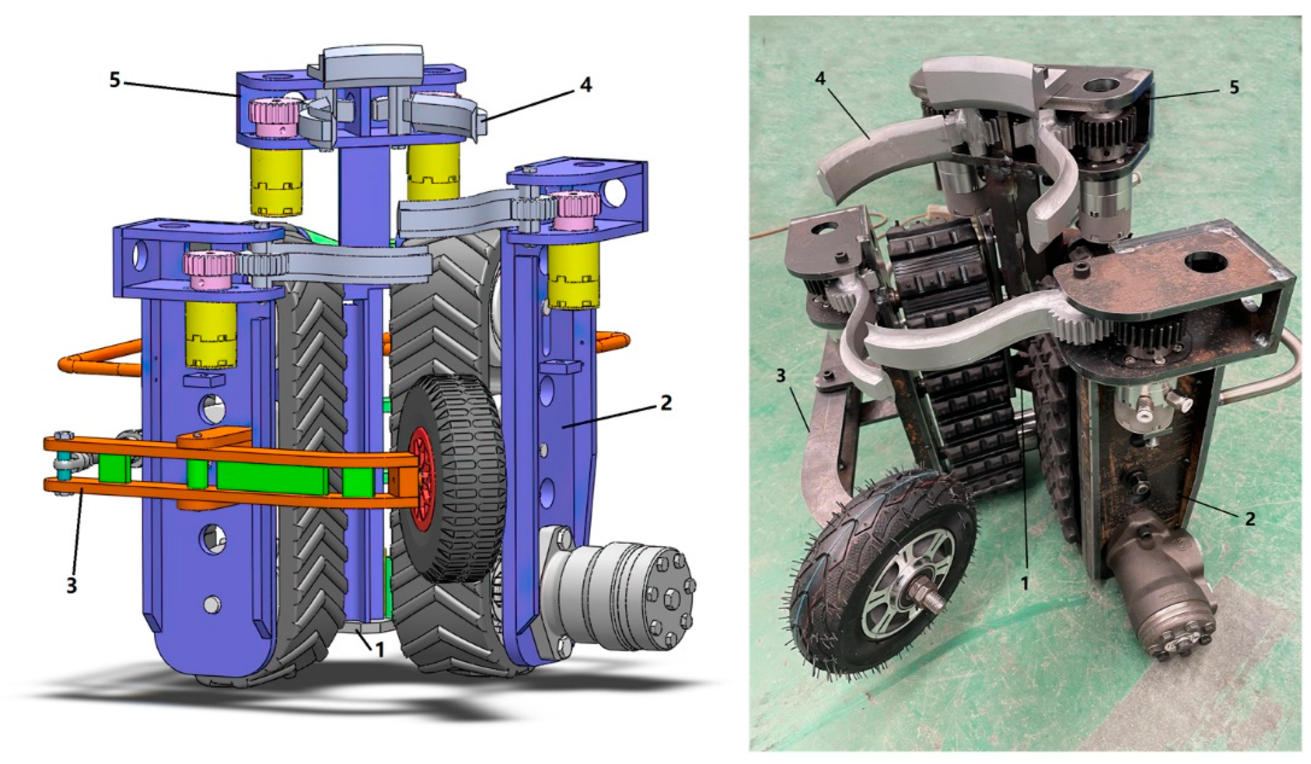
The structure of the Monkeybot is shown in
Figure 1, and mainly includes a frame, walking mechanism, clamping mechanism, cutting mechanism, and obstacle avoidance mechanism. To facilitate the replacement of fragile parts, the robot was built with a modular design idea, in which the frame is the installation carrier for the rest of the machine and made of ordinary steel (Q235). The Monkeybot can climb, hover, and descend on the tree trunk, driven by a hydraulic system. The cutting mechanism can rely on the impact of the Monkeybot in the process of climbing to prune the branches, and the tool is made of high-strength manganese steel (ZGMn13-4). The obstacle avoidance mechanism can make the Monkeybot work automatically to avoid tree knots and reduce the damage to the tree bark.
2.1. Clamping Mechanism
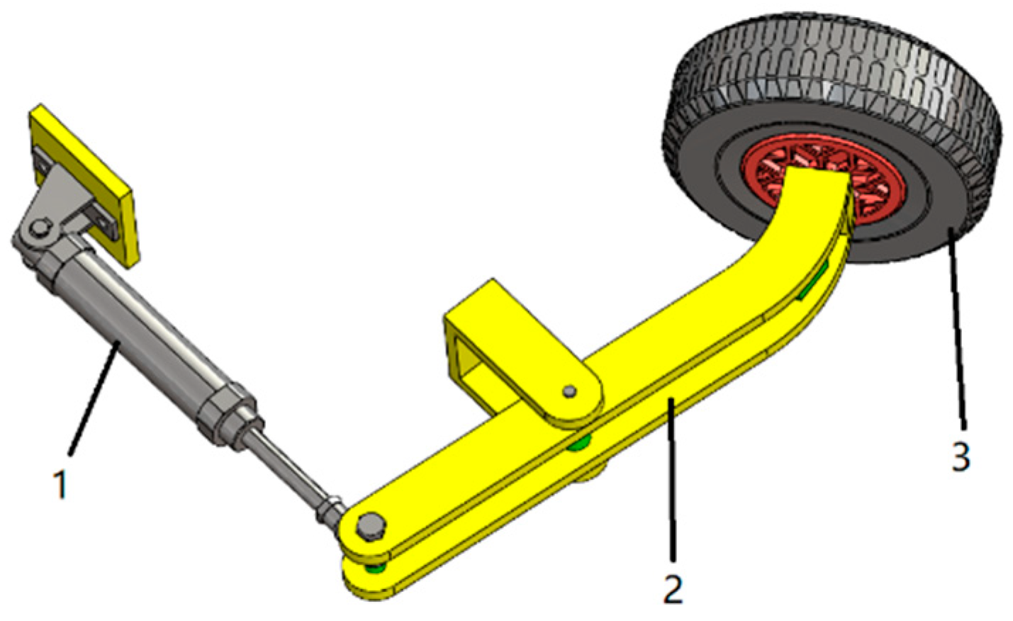
The clamping mechanism is mainly composed of the clamping cylinder, connecting frame, and clamping wheel, as shown in
Figure 2. In the working process of the Monkeybot, by keeping the pressure of the pusher cylinder constant, the contact force between the clamping wheel and the trunk is constant to achieve a self-adaptive trunk diameter change and effectively prevent safety accidents, such as slipping and falling off.
Clamping Force Estimation
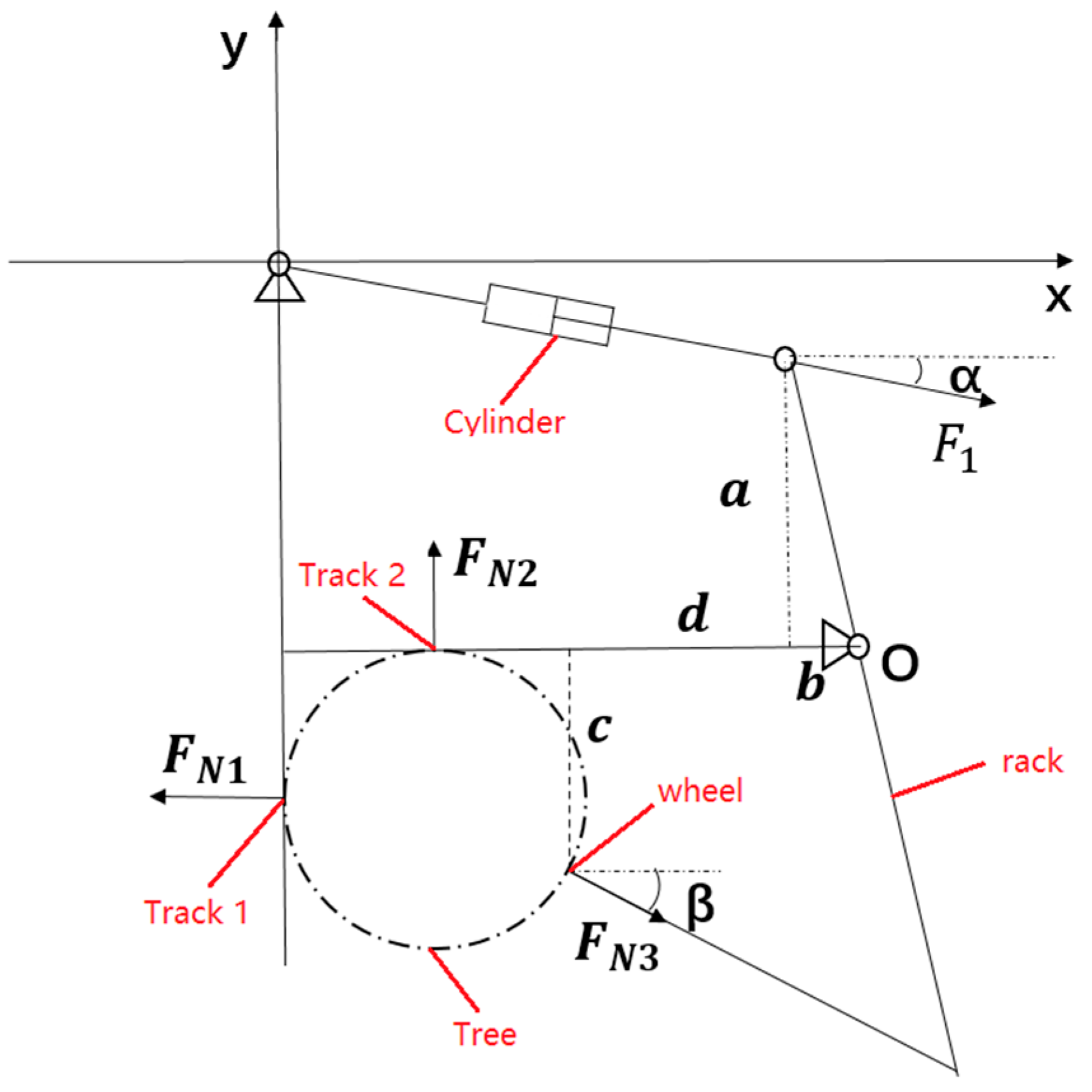
To determine the clamping cylinder thrust, the clamping mechanism was simplified, and force analysis was performed. The force analysis diagram is shown in
Figure 3.
To connect the frame, the clamping wheel and cylinder push rod, as the objects of study, can be defined by Equation (1) of the moment equation.
where
F1 is the pusher cylinder thrust;
FN3 is the clamping force of the clamping wheel.
When the trunk diameter was 20 cm, the thrust force of the pusher cylinder reached its peak, which could be obtained by measuring α = 2.17°, β = 35.46°, a = 283.08 mm, b = 99.35 mm, c = 294.19 mm, and d = 306.67 mm.
The relationship between
F1 and
FN3 can be obtained by solving for:
The frictional force
Ff is given by Equation (3):
where
Ff is the friction; μ is the friction coefficient, 0.1;
FN is the clamping force; m is the mass of the whole machine, 41.25 kg; and g is gravitational acceleration, 9.8 m/s
2.
To ensure that the whole machine worked in a balanced state and avoided generating additional moments during the climbing process, the virtual prototype was reasonably weighted in SolidWorks software and fine-tuned in the actual processing, so that Equation (4) holds.
The value of F1 = 2021.25 N can be found through the association of Equations (2)–(4), that is, the clamping force should be greater than 2021.25 N.
2.2. Cutting Mechanism
The cutting mechanism consists of one front cutter head and four side cutter heads, as shown in
Figure 4. The front cutter head is fixed on the frame, and the side cutter head is driven by four oscillating cylinders. The blade ridge of each head is raised and the edge is located on the back side of the trunk. If the Monkeybot encounters a raised or bent trunk during the climbing process, the blade ridge will collide with the trunk in contact, relying on the flexibility of the air pressure drive to achieve adaptive rebound to avoid obstacles and timely return, which can reduce the degree of damage to the bark.
Estimation of Cutting Force and Cutting Power
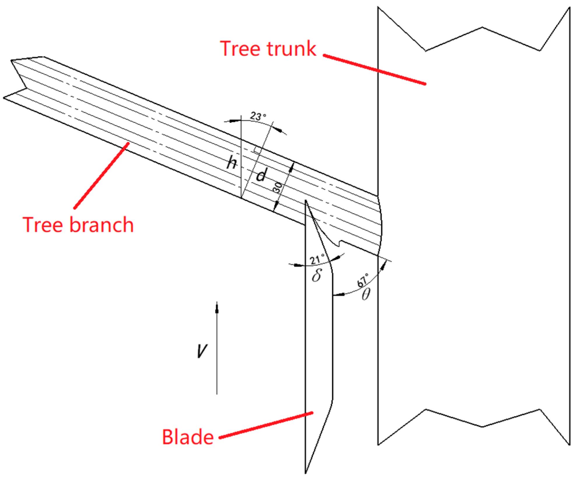
In the branch-cutting process, all factors related to the cutting area wood deformation, friction, etc., will affect the cutting force. These factors are the cutting thickness, tool dullness, tool angle, wood material properties, cutting speed, cutting direction, etc. Ideally, the Monkeybot pruning process is classified as longitudinal endwise cutting, and according to the actual research and literature [
21], the branch fiber texture direction and trunk fiber texture direction are set to 67 °. The cutting process is shown in
Figure 5, and the traditional empirical equation of shear stress is shown in Equation (5).
where
p is the shear stress, N/mm
2; h is the cutting thickness;
δ is the cutting angle, 21°;
v is the feed rate, 3 m/s;
Cρ is the tool edge passivation coefficient, 1;
k,
A,
B, and
CZ are the correction factors.
The cutting thickness h is given by Equation (6):
where
d is the branch diameter, 20 mm;
θ is the angle between the fiber direction and the cutting motion direction, 67°.
The
k,
A,
B, and
CZ correction factors are derived from Equations (7)–(10), and each parameter can be obtained by consulting the literature [
22].
where
k1 = 1.46 N/mm,
k2 = 4.81 N/mm,
A1 = 0.196 N/mm
2,
A2 = 0.549 N/mm
2,
B1 = 0.069 N/mm
2,
B2 = 0.200 N/mm
2,
C1 = 5.396 N/mm
2 and
C2 = 19.620 N/mm
2The cutting force
Fx can be derived from Equations (11) and (12).
The cutting power
Pc can be derived from Equation (13).
It is possible to find p = 8.303 MPa, Fx = 2832.32 N, and Pc = 8.50 kW.
2.3. Traveling Mechanism
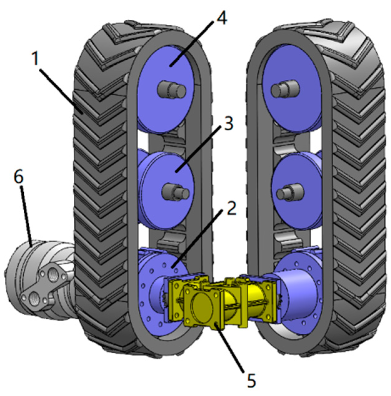
To autonomously adapt to the irregular shape of tree trunks, enhance Monkeybot’s passability and stability, reduce self-weight and reduce the degree of damage to tree bark, the Monkeybot’s travel mechanism has a single motor-driven double-track design, which mainly includes a double-track assembly and a hydraulic transmission system, as shown in
Figure 6. The hydraulic drive system is driven by a hydraulic motor through the drive shaft to drive the main wheel of the one-track assembly. The drive shaft of the main wheel of the first track assembly drives a 1:1 bevel gear right-angle commutator through a single flange-type coupling, and the 1:1 bevel gear right-angle commutator drives the main wheel of the other track assembly through a single flange-type coupling, thus realizing the synchronous operation of the dual-track assembly.
Estimation of Drive Power
The total power
Pd required by the Monkeybot in the working process includes the power
Pa consumed by overcoming gravity, the power loss
Pb caused by the climbing resistance, and the power
Pc consumed by cutting, whose relationship is shown in Equation (14).
The power
Pa consumed to overcome gravity is given by Equation (15).
The power loss
Pb caused by the climbing resistance is given by Equation (16).
The system drive efficiency is given by Equation (17).
where
η is the total transmission efficiency;
η1 is the hydraulic motor and the main wheel transmission efficiency, 0.98;
η2 is the coupling transmission efficiency, 0.95;
η3 is the 1:1 bevel gear right-angle commutator transmission efficiency, 0.90.
The driving power
P is given by Equation (18).
Substituting the relevant data, we can find the required drive power of the system, P = 12.10 kW.
2.4. Barrier Avoidance Mechanism
The obstacle avoidance mechanism consists of an upper T-steel, lower T-steel, and obstacle avoidance cylinder. The upper T-steel and lower T-steel are connected by the shaft at the top, and the lower part is connected by the obstacle avoidance cylinder. In the working process, when clamping the trunk, the obstacle avoidance cylinder provides constant tension. When the cutter head forward tilts at an angle of 5°, the upper cutter head is close to the trunk, and the upper and lower T-steel self-lock at the m point of the mechanical limit. At this time, the state of the obstacle avoidance mechanism is as shown in
Figure 7. When the obstacle avoidance mechanism meets an obstacle, such as a tree knot or small branches, the upper cutter head is tilted back due to the high-speed movement of the Monkeybot, and when the tilting angle reaches 15°, the upper and lower T-steel will be mechanically limited and self-lock at the n point.
3. Control System
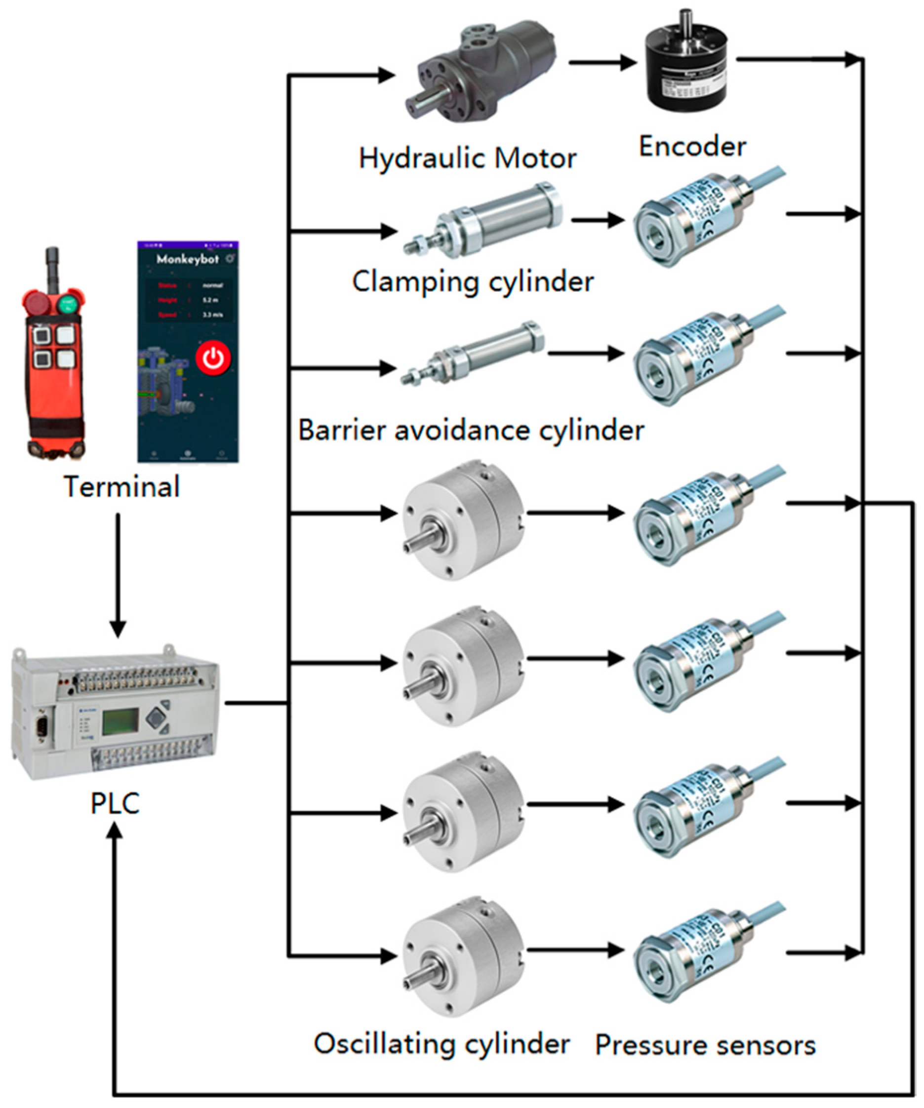
Regarding the human–computer connection, we have given the Monkeybot a Bluetooth remote control and a smartphone app. Through the adjustment of the liquid-controlled proportional flow valve and gas-controlled proportional pressure-reducing valve opening, the programmable logic controller (PLC) controls the hydraulic motor speed and each cylinder’s pressure. It also uses an optical encoder for the real-time detection of the hydraulic motor speed and a pressure sensor for the real-time detection of each cylinder. The PID algorithm is used to correct the speed of the hydraulic motor and the pressure of each cylinder in time, depending on the discrepancy between the theoretical speed and the actual speed of the hydraulic motor. The composition of the Monkeybot’s electro-hydraulic-integrated intelligent control system is shown in
Figure 8.
3.1. Hydraulic and Pneumatic System
The Monkeybot’s travel mechanism uses a hydraulic drive to achieve high-speed climbing. The clamping mechanism, cutting mechanism, and obstacle avoidance mechanism adopt air pressure transmission to achieve adaptive flexible clamping and obstacle avoidance. The hydraulic and pneumatic principles are shown in
Figure 9. The proportional throttle valve in the hydraulic system can realize the closed-loop feedback control of the hydraulic circuit to prevent slippage. The hydraulic lock enables the Monkeybot to hover anywhere in the trunk to prevent the Monkeybot from falling accidentally. The pilot-operated proportional regulator in the pneumatic system enables closed-loop feedback control of the air pressure circuit partition to ensure constant clamping force.
3.2. Ground Station
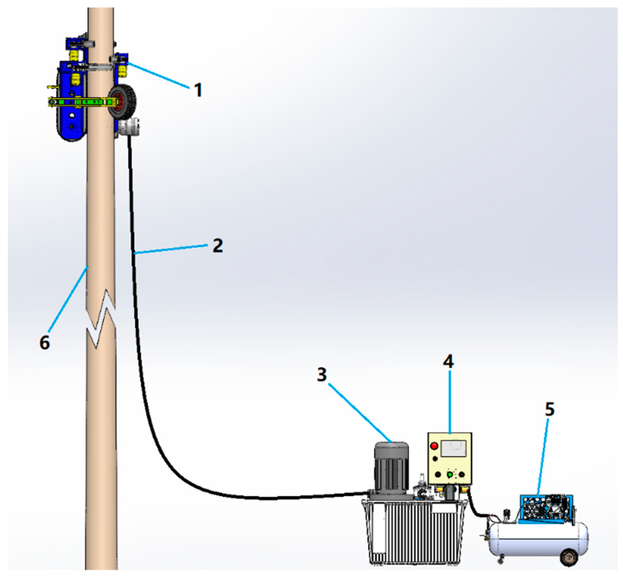
The ground station is the energy supply source of the Monkeybot and consists of a hydraulic station, air compressor, electric control box, and generator, carried by the forest transporter. Energy and information interaction with the Monkeybot uses an electric-hydraulic–pneumatic-integrated pipeline, as shown in
Figure 10. The hydraulic station provides the driving force for the Monkeybot’s climbing; the air compressor provides the clamping force for the Monkeybot’s adaptive clamping and obstacle avoidance system; the electronic control box is the control center of the whole system; the generator provides the power source for the hydraulic station and air compressor.
3.3. Human-Machine Interaction Terminal
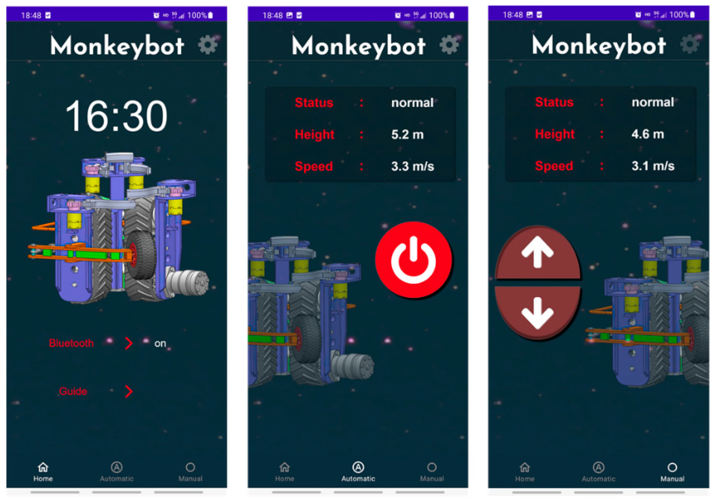
To facilitate human–machine data interaction and improve the safety of the operation process, a Bluetooth APP for smartphones was developed to achieve remote control, as shown in
Figure 11. The home page of the app allows you to make Bluetooth connections, view instructions for using the device, and other operations. The Monkeybot has two working modes—automatic and manual: In the automatic working mode, a tree can be pruned according to preset working information by pressing the start button. In the manual working mode, the up and down buttons are pressed to achieve climbing and pruning work, and the button is released to stop the work. The trunk can hover in any position under the action of the hydraulic lock.
4. Optimized Design
4.1. Experimental Principles and Methods
During the climbing process of the Monkeybot, the branch is plastically deformed by the impact cutting action of the tool and eventually breaks off. We examined the maximum shear stress on the longitudinal cutting plane of the branch during impact cutting, utilizing finite element analysis based on the theory of the distortion energy density of material mechanics. According to the theoretical analysis of the cutting mechanism, the cutting force and cutting power are proportional to the maximum shear stress. To reduce the cutting power consumption of the Monkeybot, the best combination of design parameters to reduce the maximum shear stress on the branch was explored under the premise of ensuring a good pruning effect.
Impact cutting models were built with different parameter combinations using Solidworks software and imported into Ansys Workbench Explicit Dynamic to simulate the impact cutting process respectively [
23]. The material properties were set as shown in
Table 1 [
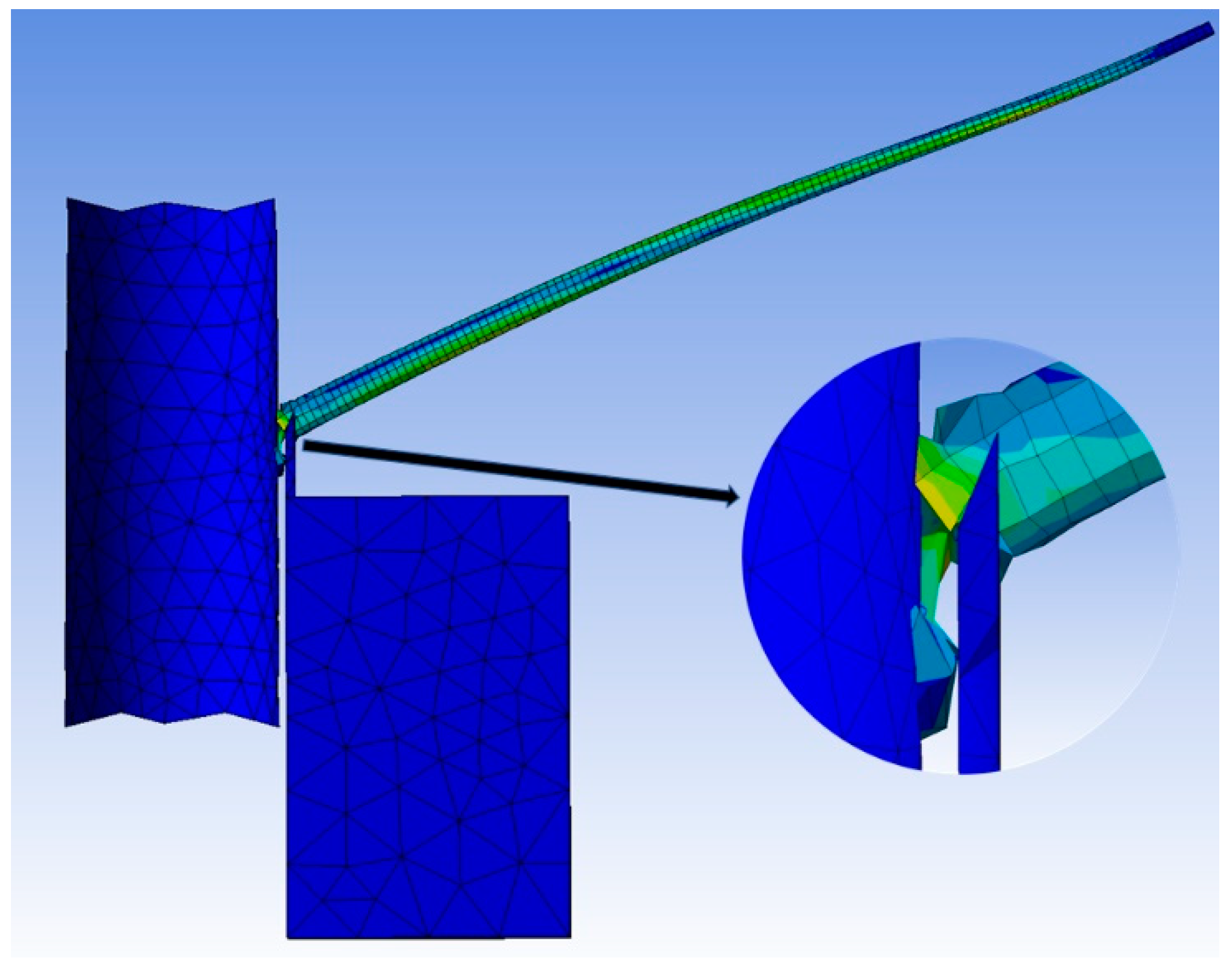
24]. The tool was set as a rigid body and the branch and trunk as flexible bodies. The global contact type was modified to friction contact, and the friction coefficient was set to 0.3. Fixing subs were added at the parts of the branch in contact with the trunk and fixing support was added at the bottom of the trunk. Using the tetrahedral meshing method, the cell size of the geometric structure was continuously optimized and adjusted, and the mesh was finally generated with a cell size of 45 mm for the tool, 25 mm for the trunk, and 5 mm for the branches. The initial speed of 3 m/s as set in the direction along the z-axis positive. The analysis time was set to 0.015 s, the erosion control was turned on, the number of step sense output control result points was increased to 100, and the shear stress of the impact cutting process was solved. The simulation test operation process is shown in
Figure 12.
4.2. Experimental Protocol and Analysis of Results
4.2.1. Experimental Protocol
The results of the preliminary theoretical design can be concluded that the tool–trunk clearance, tool edge angle, and cutting speed all affect the maximum shear stress. The tool–trunk clearance, tool edge angle, and cutting speed were selected as the test factors to analyze their effects on the maximum shear stress applied to the branch during impact cutting. The test set the tool–trunk clearance interval from 1.00 to 3.00 cm, the tool edge angle interval from 15 to 30°, and the cutting speed interval from 2.50 to 4.00 m/s. The tool–trunk clearance was set as
X1, the tool edge angle as
X2, the cutting speed as
X3, and the assessment index was the maximum shear stress
p. Based on the Box–Behnken experimental design method [
25,
26], the test factor coding of the three-factor three-level orthogonal test is shown in
Table 2.
4.2.2. Analysis of Variance
To explore the optimal working parameters of the fast-growing forest standing tree pruner, quadratic regression analysis was performed on the test results using Design Expert software [
27], and multiple regression fitting was performed to obtain the regression equation of the maximum shear stress
p test index, as shown in Equation (19). Analysis of variance was performed, and the test protocol and results are shown in
Table 3.
The variance analysis results of the regression equation are shown in
Table 4, from which it can be seen that the fit of the regression model for the maximum shear stress is highly significant (
p < 0.01), and the misfit term of each regression model is not significant, indicating that the fit of the regression model is high. The model coefficient of determination is R
2 = 0.9890, indicating that 98.90% of the variation in the maximum shear stress originates from the test factor. The model signal-to-noise ratio is 26.8119, which is greater than 4, indicating that the model is better and can be used for parameter optimization. Items
x1,
x2,
x3, and
x22 were highly significant (
p < 0.01), items
x1 x2,
x2, and
x3 were significant (
p < 0.05), and the remaining items were insignificant. The order of the effects of the test factors on the maximum shear stress was
X1 >
X2 >
X3, and the simplified regression equation was obtained by eliminating the insignificant items in Equation (19) as in Equation (20).
4.2.3. Analysis of the Influence Pattern of Interaction Factors on Indicators
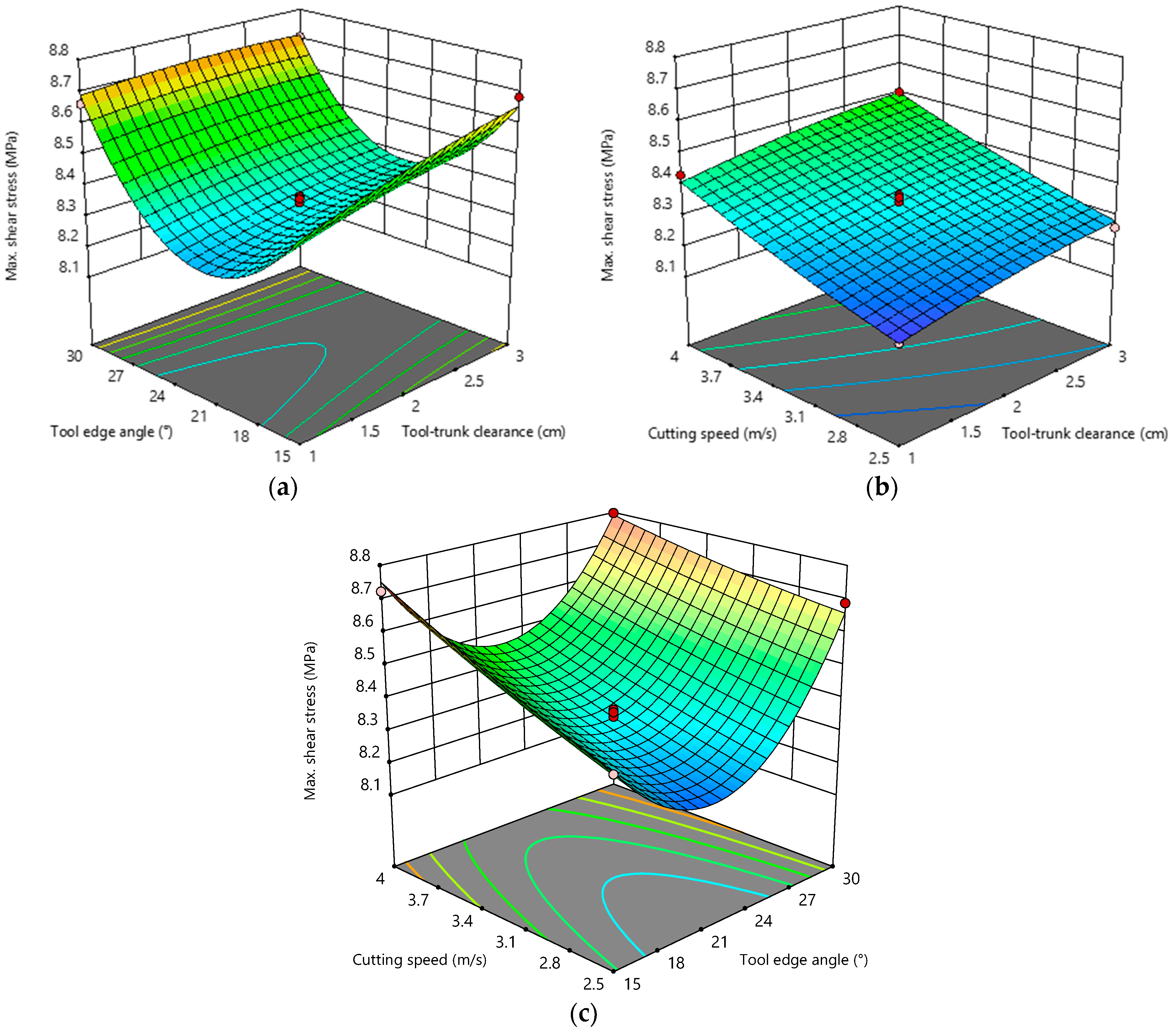
Based on the regression model of maximum shear stress, two of the test factors were placed at the 0 level, the effects of other factors on the test index were analyzed, and the response surface plots of the interaction factors on the maximum shear stress were drawn, as shown in
Figure 13.
As shown in
Figure 13a, when the cutting speed was 3.25 m/s, the maximum shear stress decreased and then increased with the increase in the tool edge angle for a certain tool–trunk clearance. This is because reducing the tool edge angle is conducive to reducing the cutting resistance, and the shear stress increases. Increasing the tool edge angle increased the contact area between the tool and the branch, and also increased the shear stress. When the tool edge angle was certain, the maximum shear stress increased with the increase in the tool–trunk clearance, but the increasing trend is not obvious, and the impact was small.
As shown in
Figure 13b, when the tool edge angle was 22.5°, the maximum shear stress increased with the increase in the cutting speed when the tool–trunk clearance was certain. The maximum shear stress also increased with the increase in the tool–trunk clearance when the cutting speed was certain.
As shown in
Figure 13c, when the tool–trunk clearance was 2 cm, the maximum shear stress increased with the increase in the cutting speed for a certain tool edge angle. For a certain cutting speed, the maximum shear stress decreased and then increased with the increase in the tool edge angle. Due to the limitation of the power source, the cutting speed design range was small, and as the cutting speed increased, the maximum shear stress tended to increase slowly, while the tool edge angle had a greater influence on the change of the maximum shear stress value.
4.2.4. Parameter Optimization and Verification
On the premise of ensuring the pruning effect, to reduce the power consumption and determine the best combination of design parameters of the pruning machine, the experiments were optimized, and the parametric mathematical model was established. The objective function and constraints are shown in Equation (21).
The parameters were optimally solved, and the results were obtained as follows: when the tool–trunk clearance was 1.00 cm, the tool edge angle was 19.471°, and the cutting speed was 2.51 m/s. The maximum shear stress reached a minimum of 8.1670 MPa.
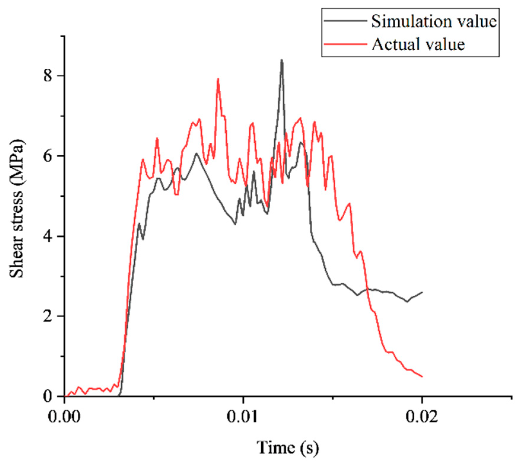
To verify the accuracy of the optimized parameter model, simulations and real measurements were performed to validate it. The model with the best combination of parameters was imported into Ansys Workbench Explicit Dynamic for a simulation, and a prototype was developed with the best combination of parameters. We installed the spoke force sensor (JLBU-1, Zhongbei Jinno Co., Ltd., Anhui, China) between the end of the tool and the tool groove and converted the voltage signal of the tool edge force measured during robot operation into a digital signal through a digital transmitter. We communicated with the host computer via Bluetooth, and the software of the host computer was used to record the real-time data changes of the cutting force of the tool edge during the robot operation. The cutting force was converted to shear stress using Equation (11), and the change in shear stress during the impact cutting was extracted and compared with the simulation value, as shown in
Figure 14. The simulation experiment results show that at 0.0030–0.0042 s, the tool instantly released the impact energy, and the shear stress on the branch increased steeply to 4.3198 Ma. At 0.0042−0.0150 s, mainly the cutting process occurred, and after 0.0150 s, branch fracture occurred. At 0.0122s, the tool edge and branch diameter position overlapped, and at this time, the generated shear stress reached a peak of 8.3238 MPa. Compared to the optimized predicted value, the error rate was 1.88%. The actual experiment results show that the maximum shear stress reached a maximum value of 7.9317 MPa at 0.0086 s, with an error rate of 2.88% compared to the optimized predicted value, because the impact process changed the angle between the branch and the trunk, and the tool edge overlapped with the branch diameter position earlier. The error between the validated experimental value and the predicted value is small, and the optimization model is feasible.
5. Performance Evaluation
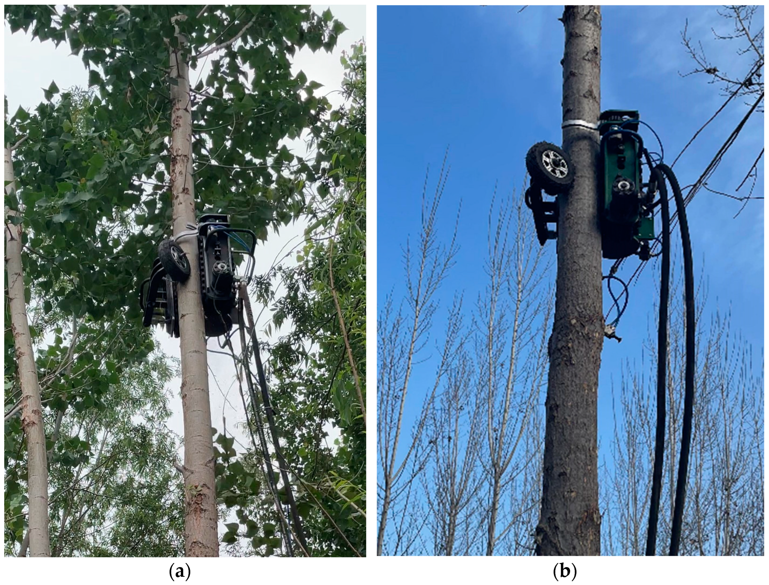
Fast-growing poplar is widely distributed in China, mostly used as protection forest and industrial timber forest. For industrial timber forests, reasonable pruning can remove snagging branches, dense branches, and competing branches, which can eliminate dead knots in the wood and improve the lumber yield and growth rate of the trunk part. We developed the first generation of a climbing and pruning robot and tested it on fast-growing poplar. We conducted late spring and winter climbing and pruning performance tests in May 2020 and December 2021 [
28], respectively, in fast-growing poplar forests in Guan County, Hebei Province. A total of 25 poplars of different diameters at breast height were selected in each season for testing, as shown in
Figure 15.
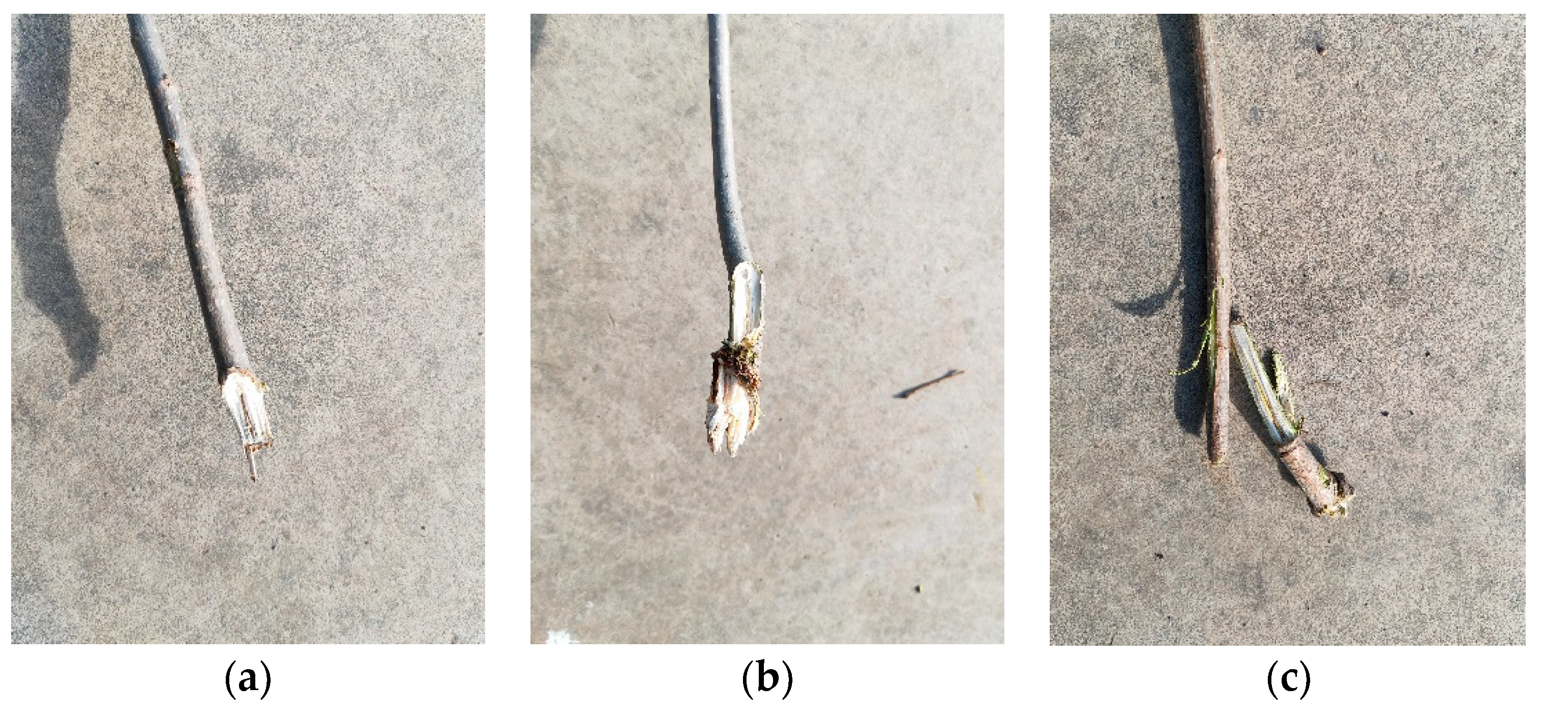
The test results show that the Monkeybot can reach a maximum climbing height of 6.03 m in late spring and 7.18 m in winter. The maximum pruning diameter was up to 2.61 cm in late spring and up to 2.79 cm in winter. Among them, trunks below 14 cm in diameter at breast height showed early slippage, and trunks above 18 cm in diameter at breast height showed insufficient impact cutting force. The larger the trunk diameter at breast height, the more likely it was to split. The overall pruning effect was better in winter than in late spring, and the pruning effect is shown in
Figure 16. Comparing late spring and winter pruning performance, the Monkeybot was optimized for winter pruning. The test metrics and their results are shown in
Table 5.
According to the research on fast-growing forests and data from the literature, the most significant percentage of fast-growing forests in the pruning stage were 14~18 cm in diameter at breast height and less than 10 m in height. To protect the crown and not affect the normal growth of the tree, the pruning height should not exceed two-thirds of the tree height, and generally, half the height is appropriate. To ensure the self-healing ability of tree wounds after pruning, a pruning diameter of 2.5 cm or less is appropriate. The performance evaluation test of the Monkeybot shows that it can meet the pruning requirements of fast-growing forests.
6. Conclusions
This article presents the design, development, and analysis of the Monkeybot, a high-speed climbing and pruning robot for standing trees in a fast-growing forest. This paper introduces the mechanical structure of the Monkeybot, theoretically analyzes the clamping mechanism and cutting mechanism, estimates the maximum clamping force and maximum cutting power, provides the theoretical basis for subsequent optimization design, and presents the design of an electro-hydraulic–pneumatic adaptive control system equipped with a remote human–machine interaction terminal.
An impact cutting process simulation test was conducted, and the mathematical regression model between the three influencing factors of the tool–trunk clearance, tool edge angle, and cutting speed and the maximum shear stress index was established. The interaction effect of each parameter on the maximum shear stress was obtained using the response surface analysis method, and the best combination of parameters was determined by the optimization analysis to reduce the cutting power consumption. The tool–trunk clearance was 1.00 cm, the tool edge angle was 19.471°, and the cutting speed was 2.51 m/s. The model was optimized and verified by the simulation and measured experiments, and the maximum shear stress was 8.3238 MPa in the simulation and 7.9317 MPa in the measurement. The error between the results and the predicted value was small, and the model is highly feasible.
The working performance of the Monkeybot was evaluated. The results of the forest test show that the average operation time of the Monkeybot pruning a single tree was less than 30 s. The best adaptable trunk diameter range was 14−18 cm at breast height, and the winter pruning effect was ideal. The maximum climbing height can reach 7.18 m, and the maximum pruning diameter can reach 2.79 cm. The climbing pruning performance of the Monkeybot can meet the pruning needs of fast-growing forests.
The successful development of the Monkeybot can provide equipment support for fast-growing forest pruning and nurturing research, but at present, the robot still has a large mass, unreasonable power distribution, a splitting phenomenon in the branches, and other problems. The follow-up will continue to study the branch impact cutting mechanism for a variety of trees to achieve the purpose of the adaptive use of different kinds of trees for different combinations of working parameters and accurate intelligent control. This equipment can also be used as a heavy-duty climbing platform, carrying various pieces of equipment to accomplish the aerial work requirements of tall trees.
7. Patents
Li, W.; Ban, Y.; Cui, Y.; Wen, J.; Kang, F.; Wang, Y. A kind of crawler-type hydraulic drive standing wood pruner. CN213907614U, 2021-08-10.
Author Contributions
Conceptualization, Y.B.; methodology, Y.B. and K.L.; software, Y.B. and S.B.; validation, Y.B., K.L. and S.B.; formal analysis, Y.B.; data curation, Y.B.; writing—original draft preparation, Y.B.; writing—review and editing, J.W., F.K. and W.L. All authors have read and agreed to the published version of the manuscript.
Funding
This research was funded by the NingXia Key Research and Development Program (Grant No. 2019BBF02009).
Data Availability Statement
Not applicable.
Conflicts of Interest
The authors declare no conflict of interest.
References
- Zambiazi, D.C.; Fantini, A.C.; Piotto, D.; Siminski, A.; Vibrans, A.C.; Oller, D.C.; Piazza, G.E.; Peña-Claros, M. Timber stock recovery in a chronosequence of secondary forests in Southern Brazil: Adding value to restored landscapes. For. Ecol. Manag. 2021, 495, 119352. [Google Scholar] [CrossRef]
- Thomas, A.; Priault, P.; Piutti, S.; Dallé, E.; Marron, N. Growth dynamics of fast-growing tree species in mixed forestry and agroforestry plantations. For. Ecol. Manag. 2020, 480, 118672. [Google Scholar] [CrossRef]
- Kadlec, J.; Novosadová, K.; Pokorný, R. Impact of Different Pruning Practices on Height Growth of Paulownia Clon in Vitro 112®. Forests 2022, 13, 317. [Google Scholar] [CrossRef]
- Yang, X.; Wang, J.; Yan, M.; Fan, S. Structure Design of Surrounding Tree-climbing and Pruning Robot. J. Physics Conf. Ser. 2021, 2029, 012052. [Google Scholar] [CrossRef]
- Wang, J.; Zheng, H.; Zhang, C.; Meng, C. Analysis and Research on Tree-climbing and Pruning Robots. J. Physics Conf. Ser. 2021, 2029, 012062. [Google Scholar] [CrossRef]
- Ueki, S.; Kawasaki, H.; Ishigure, Y.; Koganemaru, K.; Mori, Y. Development and experimental study of a novel pruning robot. Artif. Life Robot. 2011, 16, 86–89. [Google Scholar] [CrossRef]
- Mouri, T.; Kawasaki, H.; Ueki, S. Bilateral Tele-operated Hand Robot with Communicational Time Delay. IFAC-PapersOnLine 2017, 50, 12721–12726. [Google Scholar] [CrossRef]
- Gui, P.; Tang, L.; Mukhopadhyay, S. A Novel Robotic Tree Climbing Mechanism with Anti-Falling Functionality for Tree Pruning. J. Mech. Robot. 2017, 10, 014502. [Google Scholar] [CrossRef]
- Fauroux, J.-C.; Morillon, J.; Tosun, O.; Akin, H.L.; Tokhi, M.O.; Virk, G.S. Design of a climbing robot for cylindroconic poles based on rolling self-locking. Mob. Robot. Solut. Chall. 2009, 1, 447–454. [Google Scholar] [CrossRef]
- Dubey, A.P.; Pattnaik, S.M.; Banerjee, A.; Sarkar, R.; Kumar, S. Autonomous Control and Implementation of Coconut Tree Climbing and Harvesting Robot. Procedia Comput. Sci. 2016, 85, 755–766. [Google Scholar] [CrossRef]
- Megalingam, R.K.; Manoharan, S.K.; Mohan, S.M.; Vadivel, S.R.R.; Gangireddy, R.; Ghanta, S.; Kotte, S.; Perugupally, S.T.; Sivanantham, V. Amaran: An Unmanned Robotic Coconut Tree Climber and Harvester. IEEE/ASME Trans. Mechatron. 2020, 26, 288–299. [Google Scholar] [CrossRef]
- Jordan, E. Machine for Debranching Living Trees. Google Patents: Patent No. 10,470,382, 12 November 2019. [Google Scholar]
- Huo, G. Studies on Tree’s Truning Machine with Spiral Movements; Beijing Forestry University: Beijing, China, 2007. [Google Scholar]
- Zhang, J. Studies on Radio Wave Propagation Mechanisms through Plantation Forest and Control System of Pruning Machine; Beijing Forestry University: Beijing, China, 2005. [Google Scholar]
- Li, Y. Design and Test of Tree Pruning Robot System; Shandong Agricultural University: Tai’an, China, 2016. [Google Scholar]
- Shao, J. Design and Test of the Control System of the Robot to Climb Trees Pruning; Shandong Agricultural University: Tai’an, China, 2016. [Google Scholar]
- Tian, F. Optimized Design and Test of Efficient Tree-Climbing Pruning Machine for Fast-Growing Forest; Shandong Agricultural University: Tai’an, China, 2018. [Google Scholar]
- Liu, C.; Zhou, Y.; Liu, X.; Ge, Z.; Luo, R. A climbing robot for CT scanning wooden columns in ancient buildings. Sci. Silvae Sin. 2018, 54, 96–103. [Google Scholar]
- Wang, R.; Chen, H.; Li, Y.; Sun, J.; Yuan, J.; Cai, G. In Super harmonic resonance analysis of a novel controllable metamorphic pal-letizing robot mechanism with impact as its configuration change. In Proceedings of the International Conference on Mechanical Design, Beijing, China, 13–15 October 2017; Springer: Berlin/Heidelberg, Germany, 2017; pp. 1273–1289. [Google Scholar]
- Fu, G.-H.; Liu, X.-M.; Chen, Y.-F.; Yuan, J. Fast-growing forest pruning robot structure design and climbing control. Adv. Manuf. 2015, 3, 166–172. [Google Scholar] [CrossRef]
- Orlowski, K.A.; Ochrymiuk, T.; Atkins, A.; Chuchala, D. Application of fracture mechanics for energetic effects predictions while wood sawing. Wood Sci. Technol. 2013, 47, 949–963. [Google Scholar] [CrossRef]
- Pingxiang, C.; Xiaolei, G. Wood Cutting Principles and Tools; China Forestry Press: Beijing, China, 2018.
- Xie, L.; Wang, J.; Cheng, S.; Zeng, B.; Yang, Z. Optimisation and finite element simulation of the chopping process for chopper sugarcane harvesting. Biosyst. Eng. 2018, 175, 16–26. [Google Scholar] [CrossRef]
- Tao, S. Research on Trees Wind-Induced Vibration Characteristics Based on Testing Methods and Fem Simulation; Beijing Forestry University: Beijing, China, 2013. [Google Scholar]
- Wang, J.; Xie, H.; Hu, Z.; Liu, M.; Peng, J.; Ding, Q.; Peng, B.; Ma, C. Optimization of material for key components and pa-rameters of peanut sheller based on hertz theory and box–behnken design. Agriculture 2022, 12, 146. [Google Scholar] [CrossRef]
- Bakkiyaraj, M.; Gnanasekaran, S.; Samuel, S.J.C.; Murugan, K.; Selvamani, S.; Waji, Y.A. Influence of Process Parameters on Tensile Strength of the Friction Welded AA6063-T6 Joints by Box–Behnken Design Approach. Adv. Mater. Sci. Eng. 2022, 2022, 3463726. [Google Scholar] [CrossRef]
- Liquan, T.; Yongsen, X.; Zhao, D.; Zhan, S. Design and performance test of direct seed metering device for rice hill. INMATEH Agric. Eng. 2021, 64, 257–268. [Google Scholar] [CrossRef]
- Danilović, M.; Sarić, R.; Cirović, V.; Pudja, V. The impact of pruning on tree development in poplar populus× canadensis “i-214” plantations. IForest-Biogeosci. For. 2022, 15, 33. [Google Scholar] [CrossRef]
Figure 1.
Monkeybot: 1—frame; 2—walking mechanism; 3—clamping mechanism; 4—cutting mechanism; 5—obstacle avoidance mechanism.
Figure 1.
Monkeybot: 1—frame; 2—walking mechanism; 3—clamping mechanism; 4—cutting mechanism; 5—obstacle avoidance mechanism.
Figure 2.
Clamping mechanism: 1—push rod cylinder; 2—connecting frame; 3—clamping wheel.
Figure 2.
Clamping mechanism: 1—push rod cylinder; 2—connecting frame; 3—clamping wheel.
Figure 3.
Force analysis diagram.
Figure 3.
Force analysis diagram.
Figure 4.
Cutting mechanism. (a) Front cutter head; (b) side cutter heads.
Figure 4.
Cutting mechanism. (a) Front cutter head; (b) side cutter heads.
Figure 5.
Diagram of the cutting process.
Figure 5.
Diagram of the cutting process.
Figure 6.
Traveling mechanism: 1—rubber track; 2—main wheel; 3—support wheel; 4—tensioning wheel; 5—1:1 bevel gear right-angle commutator; 6—hydraulic motor.
Figure 6.
Traveling mechanism: 1—rubber track; 2—main wheel; 3—support wheel; 4—tensioning wheel; 5—1:1 bevel gear right-angle commutator; 6—hydraulic motor.
Figure 7.
Obstacle avoidance mechanism. (a) Normal working conditions; (b) working conditions when passing obstacles.
Figure 7.
Obstacle avoidance mechanism. (a) Normal working conditions; (b) working conditions when passing obstacles.
Figure 8.
Control system composition.
Figure 8.
Control system composition.
Figure 9.
Hydraulic and pneumatic principles: 1—hydraulic Station; 2—pressure-reducing valve; 3— variable throttle valve; 4—PID control; 5—three-position four-way directional valve; 6—hydraulic lock; 7—hydraulic motor; 8—encoder; 9—air compressor; 10—one-way valve; 11—two-position four-way directional valve; 12—proportional pressure-reducing valve; 13—pressure sensors; 14—clamping cylinder; 15—barrier avoidance cylinder; 16—oscillating cylinder.
Figure 10.
Ground station control principle: 1—Monkeybot; 2—electric hydraulic pneumatic integrated pipeline; 3—hydraulic station; 4—electric control box; 5—generator; 6—tree trunk.
Figure 10.
Ground station control principle: 1—Monkeybot; 2—electric hydraulic pneumatic integrated pipeline; 3—hydraulic station; 4—electric control box; 5—generator; 6—tree trunk.
Figure 11.
APP for smartphones.
Figure 11.
APP for smartphones.
Figure 12.
Simulation test operation process.
Figure 12.
Simulation test operation process.
Figure 13.
Response surface of interaction factors to maximum shear stress. (a) ; (b) ; (c) .
Figure 13.
Response surface of interaction factors to maximum shear stress. (a) ; (b) ; (c) .
Figure 14.
Trend of shear stress.
Figure 14.
Trend of shear stress.
Figure 15.
Forest test operations. (a) Late spring pruning; (b) winter pruning.
Figure 15.
Forest test operations. (a) Late spring pruning; (b) winter pruning.
Figure 16.
Pruning effect. (a) Flattening; (b) Slight Splitting; (c) Splitting.
Figure 16.
Pruning effect. (a) Flattening; (b) Slight Splitting; (c) Splitting.
Table 1.
Simulation of material properties.
Table 1.
Simulation of material properties.
| Geometrical Structures | Density/
(kg·m−3) | Young’s Modulus (GPa) | Poisson’s Ratio |
|---|
| Cutting tool | 7850 | 200 | 0.3 |
| Twig | 605 | 1.6 | 0.3 |
| Tree trunk | 639 | 2.0 | 0.3 |
Table 2.
Factors and factor levels of the experiment.
Table 2.
Factors and factor levels of the experiment.
| Level | Factor |
|---|
Tool–Trunk
Clearance X1 (cm) | Cutting Edge Angle X2 (°) | Cutting Speed
X3 (m·s−1) |
|---|
| −1 | 1.00 | 15.00 | 2.50 |
| 0 | 2.00 | 22.50 | 3.25 |
| 1 | 3.00 | 30.00 | 4.00 |
Table 3.
Test plan and results.
Table 3.
Test plan and results.
| No. | X1 | X2 | X3 | η |
|---|
| 1 | −1 | 0 | −1 | 1.1763 |
| 2 | −1 | −1 | 0 | 1.4849 |
| 3 | 0 | 0 | 0 | 1.3372 |
| 4 | 0 | 1 | 1 | 1.7973 |
| 5 | 0 | 1 | −1 | 1.6884 |
| 6 | 0 | -1 | 1 | 1.7228 |
| 7 | 0 | 0 | 0 | 1.3677 |
| 8 | 1 | 1 | 0 | 1.7053 |
| 9 | −1 | 0 | 1 | 1.4313 |
| 10 | −1 | 1 | 0 | 1.6611 |
| 11 | 0 | 0 | 0 | 1.3594 |
| 12 | 0 | 0 | 0 | 1.3452 |
| 13 | 1 | −1 | 0 | 1.6837 |
| 14 | 1 | 0 | −1 | 1.2611 |
| 15 | 0 | −1 | −1 | 1.4287 |
| 16 | 1 | 0 | 1 | 1.5023 |
| 17 | 0 | 0 | 0 | 1.3116 |
Table 4.
Analysis of variance for maximum shear stress.
Table 4.
Analysis of variance for maximum shear stress.
| Variance Sources | Some of Deviations Squares | Freedom of Degree | Mean Square | F | P |
|---|
| Model | 0.5610 | 9 | 0.0623 | 69.72 | <0.0001 ** |
| x1 | 0.0199 | 1 | 0.0199 | 22.24 | 0.0022 ** |
| x2 | 0.0354 | 1 | 0.0354 | 39.57 | 0.0004 ** |
| x3 | 0.1011 | 1 | 0.1011 | 113.06 | <0.0001 ** |
| x1 x2 | 0.0060 | 1 | 0.0060 | 6.68 | 0.0362 * |
| x1 x3 | 0.0000 | 1 | 0.0000 | 0.0533 | 0.8241 |
| x2 x3 | 0.0086 | 1 | 0.0086 | 9.59 | 0.0174 * |
| x12 | 0.0008 | 1 | 0.0008 | 0.8596 | 0.3847 |
| x22 | 0.3867 | 1 | 0.3867 | 432.52 | <0.0001 ** |
| x32 | 0.0006 | 1 | 0.0006 | 0.6827 | 0.4359 |
| Residual | 0.0063 | 7 | 0.0009 | | |
| Lack of fit | 0.0044 | 3 | 0.0015 | 3.07 | 0.1536 |
| Pure Error | 0.0019 | 4 | 0.0005 | | |
| Total | 0.5672 | 16 | | | |
Table 5.
Test indicators and their results.
Table 5.
Test indicators and their results.
| Diameter at Breast Height /cm | Number of Tests | Average Operating Time for a Single Tree (s) | Maximum Climbing Height (m) | Maximum Pruning Diameter (cm) | Overall Pruning Effect |
|---|
| Late Spring | Winter | Late Spring | Winter | Late Spring | Winter | Late Spring | Winter | Late Spring | Winter |
|---|
| 10~12 | 5 | 5 | 25.42 | 22.32 | 4.32 | 5.88 | 1.95 | 2.21 | Flattening | Flattening |
| 12~14 | 5 | 5 | 26.51 | 23.98 | 4.73 | 6.32 | 2.13 | 2.34 | Flattening | Flattening |
| 14~16 | 5 | 5 | 28.33 | 27.11 | 5.82 | 6.83 | 2.33 | 2.58 | Slight Splitting | Flattening |
| 16~18 | 5 | 5 | 28.90 | 26.74 | 6.03 | 7.18 | 2.61 | 2.79 | Slight Splitting | Slight Splitting |
| 18~20 | 5 | 5 | 26.87 | 24.83 | 5.23 | 6.40 | 2.31 | 2.49 | Splitting | Splitting |
| Publisher’s Note: MDPI stays neutral with regard to jurisdictional claims in published maps and institutional affiliations. |
© 2022 by the authors. Licensee MDPI, Basel, Switzerland. This article is an open access article distributed under the terms and conditions of the Creative Commons Attribution (CC BY) license (https://creativecommons.org/licenses/by/4.0/).
