Article

Refined Modeling Method and Analysis of an Electromagnetic Direct-Drive Hydrostatic Actuation System

1
School of Transportation and Vehicle Engineering, Shandong University of Technology, Zibo 255000, China
2
School of Mechanical Engineering, Shandong University of Technology, Zibo 255000, China
*
Author to whom correspondence should be addressed.
Actuators 2022, 11(10), 281; https://doi.org/10.3390/act11100281
Submission received: 9 September 2022 / Revised: 23 September 2022 / Accepted: 27 September 2022 / Published: 30 September 2022
(This article belongs to the Special Issue Flow Control Actuators and Their Diverse Fluid Dynamic Applications)

Abstract

:
The hydrostatic actuation system based on linear actuators improves the complex piston force and long transmission path of the traditional electro-hydrostatic actuator (EHA). However, new nonlinear factors in the linear actuator and direct-driven piston are introduced into the system, which present challenges to system modeling and control. To improve the accuracy of system performance prediction, this paper analyzed the working characteristics of an electromagnetic direct-drive hydrostatic actuation system (EDHAS). A dynamic model of the electromagnetic linear actuator including the LuGre friction model was established. The high-pressure internal leakage of the direct-drive pump was described by an inclined eccentric leakage model. The Karnopp friction model was applied to solve the problem of switching between viscous and sliding friction in a cylinder. The hydraulic components model was established based on AMESim, and the electromagnetic linear actuator model and the system controller model were established in Matlab/Simulink, to establish a refined electromechanical–hydraulic co-simulation model of the EDHAS with electromagnetic, mechanical, hydraulic, and control coupling. A system performance test platform was built. The simulation results of the direct-drive piston displacement, the system pressure, the system flow rate, and the cylinder displacement match well with experimental results, which verifies the validity and accuracy of the refined modeling method.

1. Introduction

The electro-hydrostatic actuation system has the advantages of strong load capacity and high power density. It has been widely used in aerospace, aviation, shipping, and other fields [1,2]. With the development of related technologies, its potential in control actuation systems for small- and medium-sized equipment areas such as robotics and automobiles is gradually gaining attention [3].
The traditional electro-hydrostatic actuation system adopts the mode of rotating-motor–swash-plate piston-pump–actuator-cylinder in series. Many teams have conducted in-depth research on system design and control [4,5,6,7,8]. The electro-hydrostatic actuator based on linear drive devices has great potential in the fields of robots and electric vehicles. A linear piston pump driven by an electromagnetic linear oscillating motor was designed, and a new type of cooperative flow distribution structure was proposed in [9]. An integrative giant magnetostrictive material-based electro-hydrostatic actuator (GMEHA) was designed in [10]. A newly developed single-rod EHA that operates in four quadrants was proposed in [11], and a QFT position controller was designed for this purpose. In [12] a new type of electro-hydraulic actuator system with energy recovery was proposed, and the virtual experimental prototype structure of the electro-hydrostatic actuator was designed.
An electro-hydrostatic actuator is a typical electromechanical–hydraulic integrated system, whose working process is seriously coupled with multiple disciplines, and the system modeling is developing from the traditional method based on the solution of state equation to the method based on the coupling of multiple disciplines. The traditional method neglects many nonlinear factors, which is feasible to analyze the stability of the control system and the preliminary analysis of the system performance and has the advantage of fast calculations. The popular method can predict system performance more accurately, but it requires a relatively long calculation time. References [13,14] and other research teams have established multidisciplinary models of mechanics–electronics–hydraulics integration systems by using AMESim software or analytical models, respectively [15,16]. Reference [17] modeled EHA-based active suspension based on a power bond graph. Multidisciplinary modeling is often based on the transfer function to build the driving unit model and linearize the hydrostatic pump model, and then determine the model parameters through system identification [18,19]. References [20,21] studied and identified the model parameters by combining theoretical modeling with system identification modeling. Lee et al. used the signal compression method to identify the linear link parameters in EHA [22]. A genetic algorithm was used to realize linear model identification of EHA in [23].
In the study of system control performance, the characteristics of the system drive unit are often simplified, even to a fixed signal input. However, such simplification is more conservative than needed when high-performance control and performance prediction of the system are required. Therefore, there is a need for further research on fine-grained modeling methods for mechatronic systems with electromagnetic, mechanical, hydraulic, and control coupling.
To further improve the performance prediction ability of the multidisciplinary model, the group proposed an electromagnetic direct-drive hydrostatic actuation system in which an electromagnetic linear actuator directly drives a plunger pump and thus realizes the actuated cylinder volume control, and established a multidisciplinary simulation model [24]. In [25], a refined EHA model considering the nonlinearity of permanent magnet synchronous motor and the quantitative piston pump model considering the flow pulsation and external leakage were established. However, the EHA system has a large number of nonlinear factors such as drive unit nonlinearity, variation of pump flow volume characteristics, and nonlinear characteristics of check valves, which can lead to degradation of its dynamic/steady-state performance [26]. The electromagnetic linear actuator directly drives the hydraulic pump piston, introducing new nonlinear characteristics to the system while inherent nonlinear factors such as system friction significantly affect the servo performance of the electromagnetic linear actuator [27]. Therefore, refined modeling is both a common fundamental problem for EHA and a basis for analysis and control research of EDHAS.
This paper establishes a refined electro-hydraulic joint simulation model of electromagnetic direct-drive hydrostatic actuation system considering the dynamic friction of linear actuator LuGre, tilting eccentric leakage of hydraulic pump, and nonlinear friction of actuating cylinder Karnopp by analyzing the working characteristics of the system and verifies the validity and accuracy of the modeling through experiments.

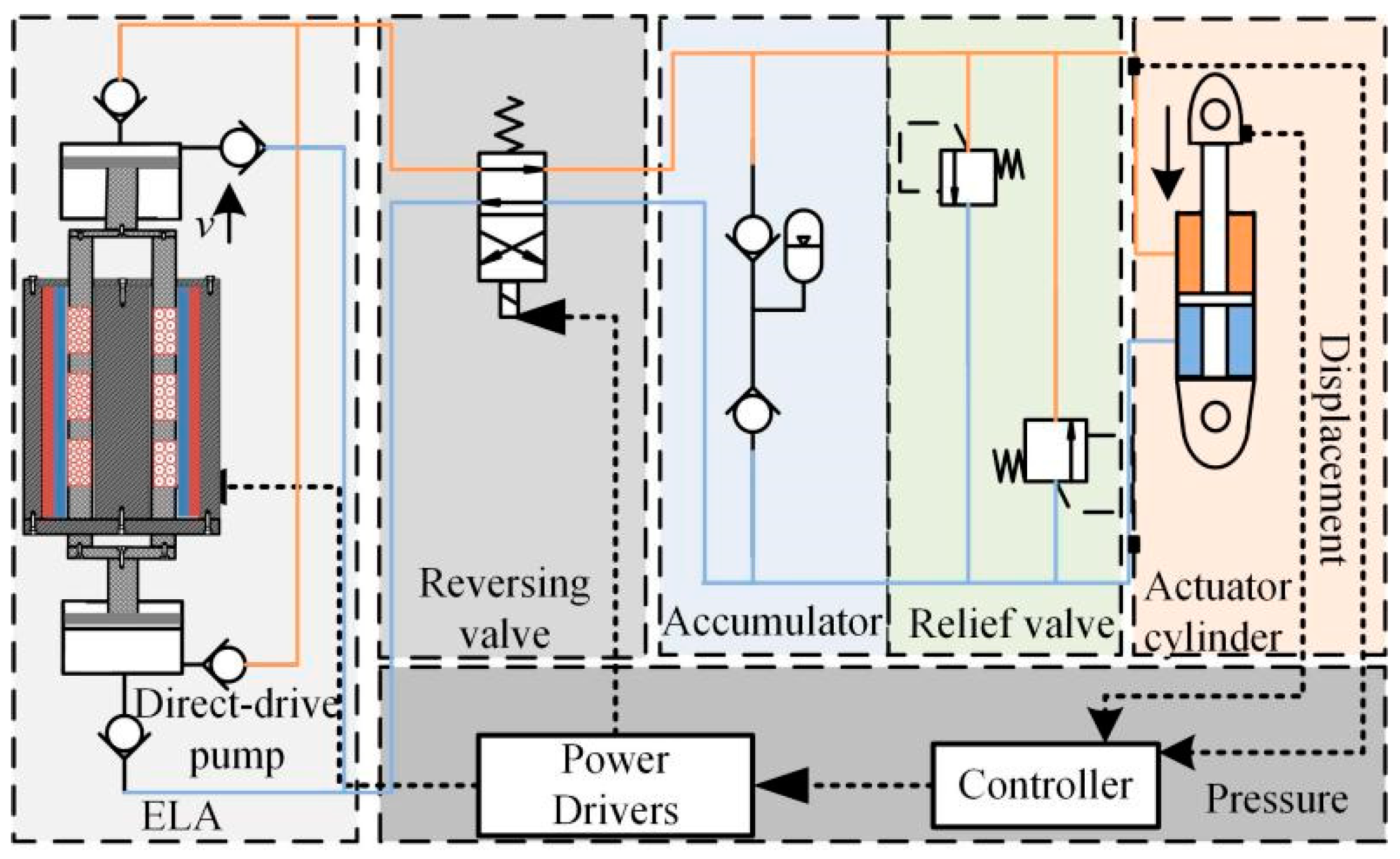
2. Working Principle of EDHAS

The structure of the electromagnetic direct-drive hydrostatic actuator system is shown in Figure 1, which mainly consists of an electromagnetic linear actuator, direct-drive pump, reversing valve, accumulator, relief valve, and actuator cartridge. The electromagnetic linear actuator with quick response to directly drive the piston. The direction of the output hydraulic oil of the direct-drive pump is constant. The function of the reversing valve is to control the direction of the hydraulic oil flowing into the actuator cylinder. When the movement direction of the actuator cylinder needs to be changed, the reversing valve switches once. Therefore, through the control of the electromagnetic linear actuator and the reversing valve, the movement speed and direction of the actuator cylinder can be controlled, respectively.
Compared with the hydrostatic actuator adopting the control mode of rotating-motor–swash-plate piston-pump–actuator in series, the EDHAS proposed by the research group adopts the high-power density moving-coil electromagnetic linear actuator with a quick response to directly drive the piston. See reference [27] for the working principle of the moving-coil electromagnetic linear actuator. Compared with the frame of a rotating motor combined with a swash-plate piston pump of a traditional electro-hydrostatic actuator, the EDHAS omits the intermediate mechanical conversion mechanism, controls the output hydrostatic oil to flow through the piston motion frequency and amplitude of the direct-drive pump, and realizes the motion control of the actuator cylinder by combining with the electromagnetic reversing valve, which effectively increases the response speed and improves the force condition of the piston.

3. Multiphysics Coupling Modeling

3.1. Electromagnetic Linear Actuator Modeling

The electromagnetic linear actuator is a coupled electromagnetic–mechanical system, and the mathematical model is described in [28].
dI ( t ) dt = R L i K e L v + U ( t ) L v ˙ = F f cv M + K m M I ( t ) F d M x ˙ = v
where U is the phase voltage, R is the resistance of the coil; L is the inductance, I is the current; v is the speed of the mover; Fe is the electromagnetic force; Km is the electromagnetic force coefficient; Fd is internal and external uncertain interference forces; M is the mass of the mover of the motor; x is the displacement of the mover; Ff is the friction force received during the movement of the mover; and the damping coefficient c is 20 N/(m/s).
To achieve accurate modeling of the electromagnetic linear actuator, the LuGre dynamic friction model is adopted:
F f = σ 0 z + σ 1 d z d t + σ 2 v d z d t = v v g ( v ) z σ 0 g ( v ) = F C + ( F S F C ) e ( v / v s ) 2
where σ 0 , σ 1 and σ 2 are the model parameters; z is the internal friction state; vs is the empirical coefficient of Stribeck; g ( v ) a function of v; FC is the Coulomb friction; and FS is the static friction.

3.2. Modeling of Electromagnetic Direct-Drive Pump

The actuator of the electromagnetic linear actuator and the pump piston are solidly connected. It achieves accurate action under the action of electromagnetic force and internal and external nonlinear interference, and the power balance equation of the direct-drive pump piston is obtained as:
M + m p + m r x ¨ = F e F f P 1 P 0 S p c + c p x ˙
where mp and mr are the masses of the piston of the direct-drive pump and its mechanical fixed parts with the actuator mover, respectively; cp is the damping coefficient of the plunger pump; P0 and P1 are, respectively, the pressures of the pump cavities of the plunger pumps at both ends; and Sp is the cross-sectional area of the plunger.
Considering the actual situation in which a small amount of air is inevitably trapped in the fluid, which will lead to a sharp drop in the bulk modulus of the hydraulic fluid, the effective bulk modulus of the hydraulic fluid in the actual process is [29]:
1 β e = V a V a + V o p a p 1 2 + 1 V a V a + V o p a p 1 1 β f
where β e is the effective bulk elastic modulus; pa is the atmospheric pressure; p1 is the pressure exerted on the hydrostatic oil under the compression condition; β f is the bulk modulus of pure hydrostatic oil; and Va and Vo are the volumes of air and hydrostatic oil in the trapped oil, respectively.
For the actual problem of high-pressure leakage in the piston pump, the mathematical model of the pump chamber unit of the electromagnetic direct-drive piston pump is obtained as follows:
p ˙ = β e ρ ˙ ρ = β e S p x ˙ Q o + Q i Q L S p ( L x )
where Qo is the outlet flow; Qi is the inlet flow; and QL is the leaked flow.
Considering the high/low pressure difference between the two ends of the sealing surface of the piston of the direct-drive pump when it reciprocates at high frequency, concentric leakage or eccentric leakage rarely occurs in the actual process. Considering the error of machining accuracy and the existence of the mating gap, the piston and the pump cylinder in the direct-drive piston pump will have an inclined contact, and the contact position is schematically shown in Figure 2.
As shown in Figure 2, the rectangular coordinate system takes the radial axis of the direct-drive pump cylinder as the x axis, and the intersection of the axial centerline of the plunger cylinder and the radial axis as the coordinate center O. The point a on the axis is taken and δ is the eccentricity on the end face. The eccentricity and eccentricity of the plunger piston at this position are:
e ( x ) = δ x L / 2 = 2 δ x L
ε ( x ) = e ( x ) δ = 2 x L
Take the annular gap with length dx. Denote the pressure difference as dp, and integrate it:
Δ p = d p = 2 0 L 2 12 Q L 0 μ π d δ 3 d x 1 + 1.5 ( 2 x / L ) 2 = 8.68 Q L 0 μ L π d δ 3
where QL0 is the laminar flow rate of the annular gap with inclination and eccentricity; d is the piston diameter; Δ p is the pressure difference between the pump cavities before and after the piston of the direct-drive pump; δ is the single-sided fit clearance; μ is the fluid viscosity; and L is the matching length of piston and cylinder.
After fully considering the shear flow leakage, the total leakage is:
Q L = π d δ 3 8.68 μ L Δ p + π d δ v 0 2

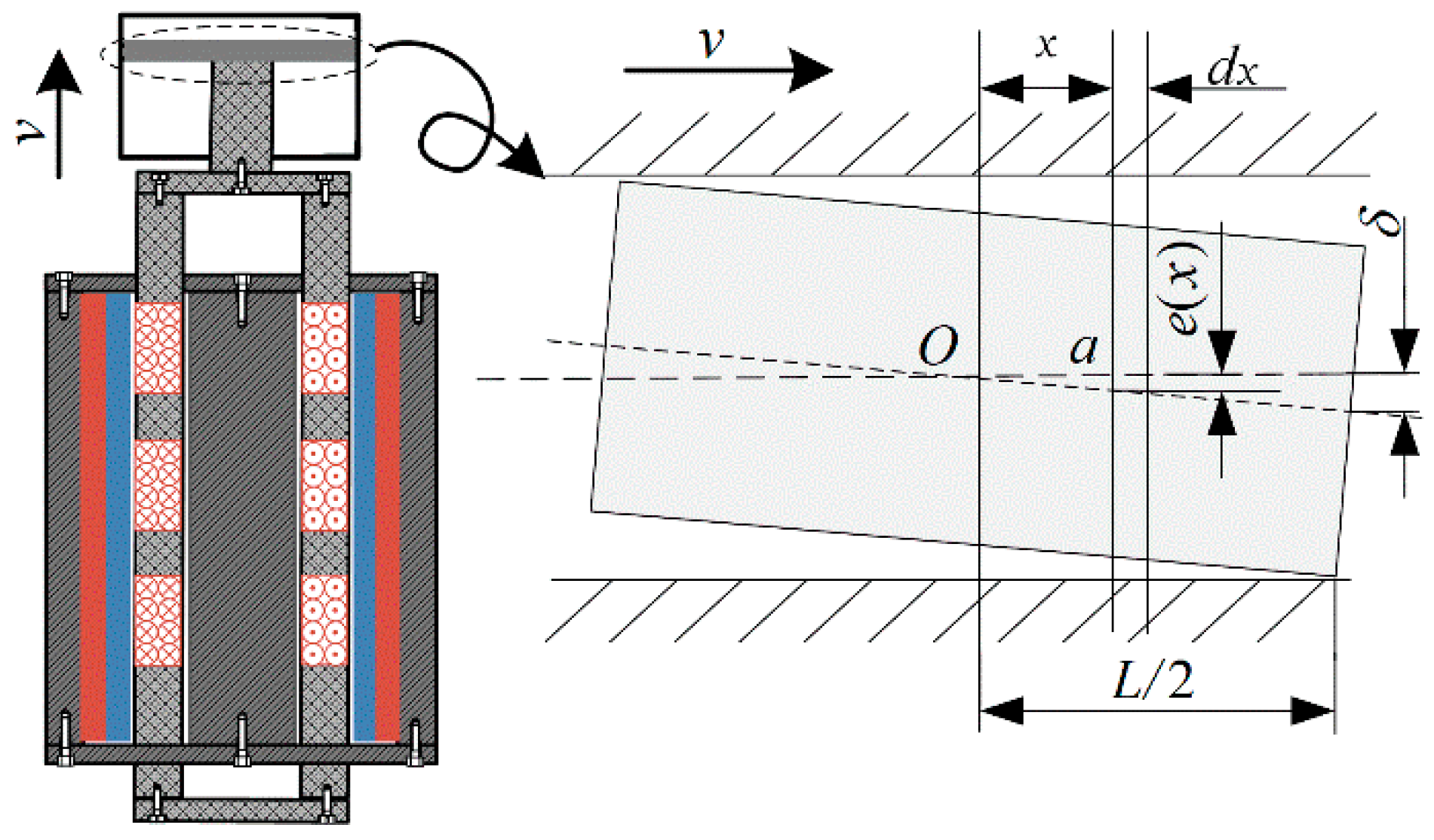
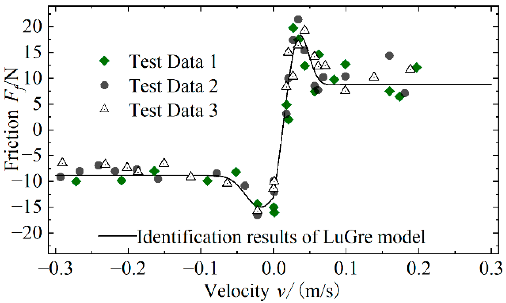
3.3. Modeling of Actuator Cylinder

High-pressure oil in the EDHAS flows directly into the actuation cylinder through the reversing valve. Considering that the oil pressure in one side of the hydrostatic actuation cylinder is small, the flow continuity equation of the actuation cylinder can be simplified as follows:
Q ai = A x ˙ a + A x a 0 + x a β e d P ah d t + K il P ah Q ao = A x ˙ a + K il P ah
where Qai is the flow rate of the oil inlet of the cylinder cavity of the actuator cylinder; A is the effective area of the actuator piston; xa is the displacement of the output rod of the actuator; xa0 is the initial position of the output rod of the actuator cylinder; Pah is the pressure in the high-pressure chamber of the oil inlet chamber of the actuator cylinder; Pal is the low-pressure chamber pressure of the oil outlet chamber of the actuator; Qao is the flow rate of oil outlet in the cylinder cavity of the actuator cylinder; and Kil is the internal leakage coefficient of the actuator cylinder.
Considering the clearance fit between the piston rod of the actuator cylinder and the cylinder cavity, the influence of friction is inevitable. The equilibrium equation of the piston rod is as follows:
M a x ¨ a = ( P ah P al ) A c a x ˙ a F fa F elf
where Ma is the total mass of the piston rod and the load of its fixed part; ca is the viscous damping of the piston rod and load; Ffa is the friction force suffered by the piston rod during its motion; and Felf is the external load force.
Considering the Karnopp friction model’s low requirement on the measurement accuracy of velocity signal, while taking into account the advantages of viscous damping, Coulomb friction, and static friction without the need to solve complex mathematical equations, avoiding the problem of switching between viscous and sliding friction equations of state. The friction force in the process of piston rod actuation is expressed as [30]:
F fa = sgn ( x ˙ a ) F fda , x ˙ a > x ˙ min sgn ( x ˙ a ) max ( F , F fm ) , x ˙ a x ˙ min
where F = ( P ah P al ) A a m 1 g is the force acting on the piston, and Ffda is the dynamic friction; Ffm is the maximum static friction; and x ˙ min is the critical speed.

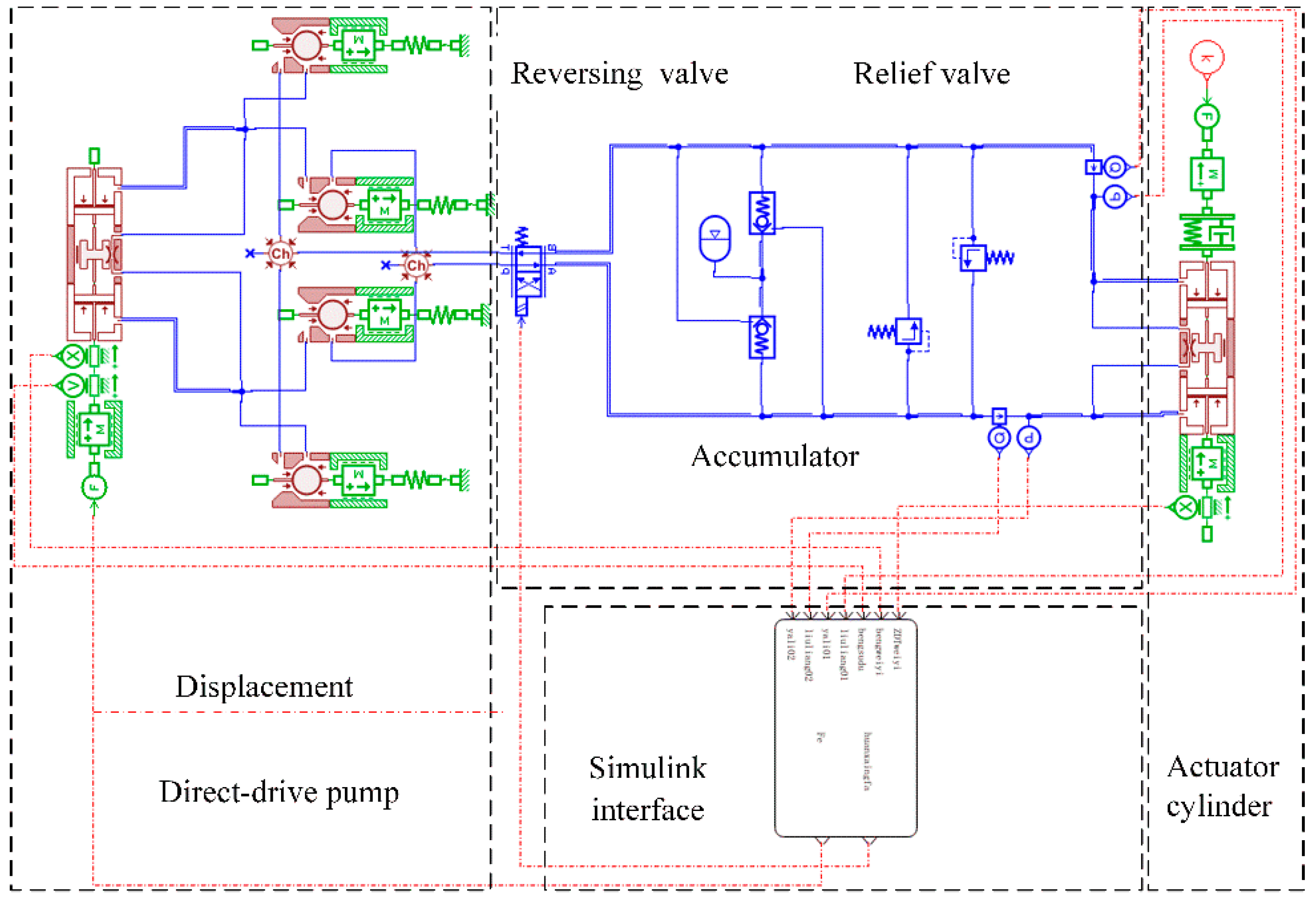
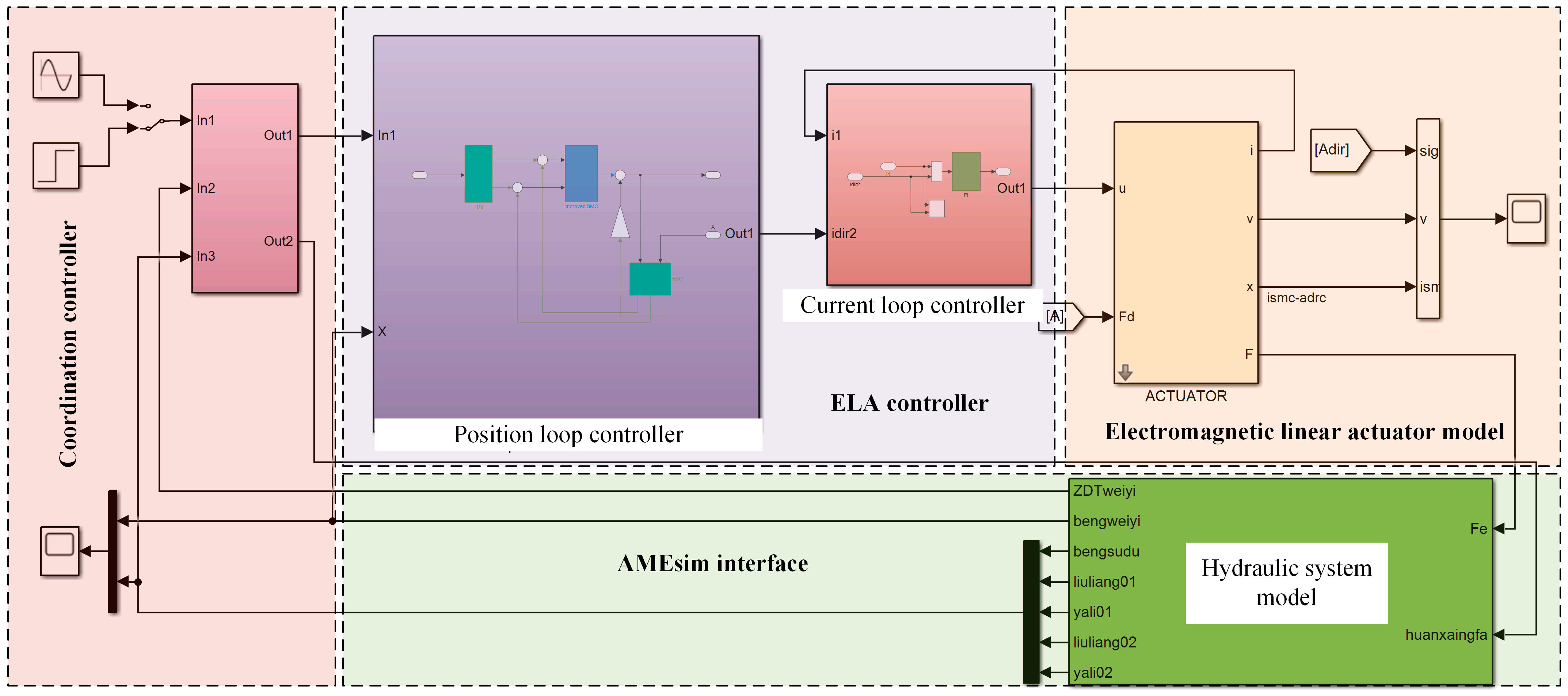
3.4. Establishment of Co-Simulation Model

Based on AMESim, the components and pipelines of the system, such as direct-drive pump, electromagnetic reversing valve, accumulator, and valves were modeled [31]. After that, the parameters of the corresponding modules, as well as the conditions of friction, damping, and leakage, are set according to the mathematical models in Section 3.2 and Section 3.3. In the simulation modeling, the components of the Mechanical library, the Hydraulic library, and the Hydraulic Component Design (HCD) library of the AMESim software were utilized to build a refined model of the components for the actuation system. In particular, the simulation model of steel ball type check valve was built by MAS005 sub-model with BAP016 and BAP24 sub-models in HCD library. The simulation model of piston pump and hydraulic actuator was built by MAS005 sub-model, BAP11 sub-model, and BAF02 sub-model. The RV010 sub-model and CV005 sub-model in the Hydraulic library were adopted to build the stabilized safety system. Finally, the variable data were combined with Simulink through the Interface block interface module for real-time processing and analysis.
At the same time, the model of the electromagnetic linear actuator and system controller are established based on the state equation in Matlab/Simulink, and then the co-simulation model of mechanical, hydrostatic, and control subsystems of EDHAS is established through the communication between AMESim and Matlab/Simulink. The controller model includes a coordination controller and an electromagnetic linear actuator controller. The former is responsible for the coordination of system flow and pressure, while the latter realizes the servo control of the direct-drive pump piston motion trajectory. The related research will be reported in the subsequent papers. To further improve the dynamic performance and steady-state accuracy of the electromagnetic linear actuator (EMLA) for the direct-drive system, the adaptive non-singular terminal sliding mode controller (ANTSMC) based on an improved disturbance observer (IDOB) is proposed [31]. Based on the joint simulation of these two pieces of software to achieve a realistic and accurate simulation of the complex operating conditions of the EDHAS, the basis for further research on the control of the system drive unit, system coordination methods, and system performance optimization is laid. The simulation model is shown in Figure 3 and Figure 4, and the main parameters of the system are shown in Table 1.

4. Experimental Verification and Analysis

4.1. Experimental Setup

The performance test platform of EDHAS is built as shown in Figure 5, which mainly consists of an electromagnetic linear actuator, direct-drive pump, low-pressure accumulator, reversing valve, actuator cylinder, flow sensor, displacement sensor, pressure sensor, and other components. The control signal of the upper computer is transmitted to the lower computer controller through the network cable and controls the power drive module to control the drive voltage of the electromagnetic linear actuator, which drives the direct-drive pump to output hydraulic oil, and the hydraulic oil pushes the piston rod of the actuator cylinder to move. RTU-BOX, a rapid control prototype system, is adopted as the controller. SN51B of PUKU Company is used as the flow sensor and PCM320 is used as the pressure sensor. The displacement sensor is MTL3 of MIRAN Company. The DC-regulated power supply voltage was set to 48 V through data acquisition [32]. The results of the discriminated LuGre dynamic friction model of the electromagnetic linear actuator based on the least squares method were obtained as shown in Figure 6.

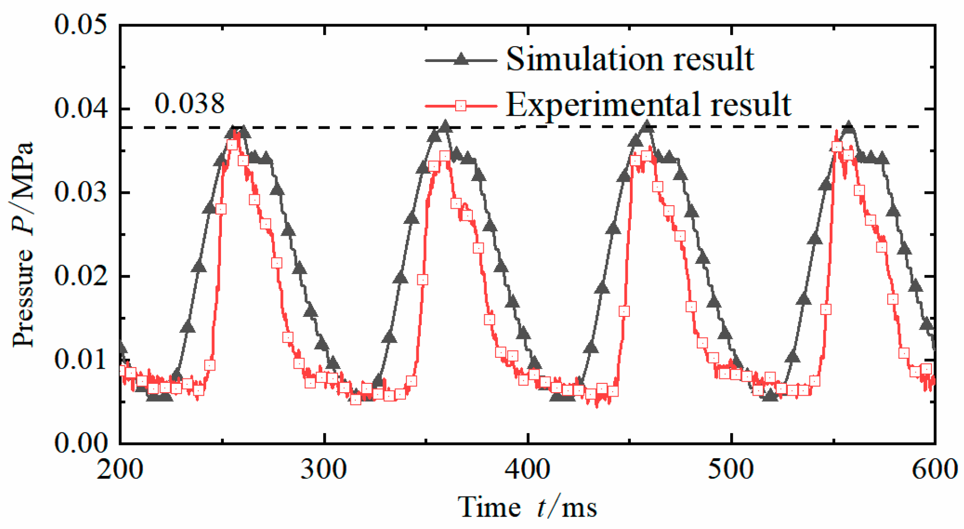
4.2. Pressure Test and Analysis of Actuating System

Setting the target desired displacement of the electromagnetic linear actuator to a sinusoidal curve at 10 Hz and setting no load on the actuator cylinder, the direct-drive pump piston motion curve was obtained as shown in Figure 7. The simulation and experimental results of the direct-drive pump piston motion curve are in good agreement, and both can achieve better tracking of the sinusoidal target displacement. There are always errors in the experimental results; while the experimental displacement tracking error is slightly larger than the simulation tracking error, it can still meet the control requirements of EDHAS. This is due to the inevitable mixing of oil with air during the actual measurement, which reduces the bulk modulus of liquid. In addition, there is also the limitation of nonlinear time-varying factors such as temperature rise. Both the simulation results and the experimental results have different degrees of lag response. After a stable operation, the phase lag of simulation and experiment at the peak is 1.21 and 1.57, respectively, and the amplitude attenuation is 0.57% and 0.86%, respectively, which better reflects the amplitude–frequency characteristics of electromagnetic linear actuator servo control. The validity and accuracy of refined electromechanical–hydraulic integration modeling are proven.
Figure 8 shows the pressure test and simulation results of the hydraulic pipeline at the outlet of the direct-drive pump. In the initial stage, the oil pressure of the pipeline did not increase. This is because a small amount of air is inevitably entrained in the oil in the actual situation, which will lead to the decrease of the effective bulk modulus of the hydraulic oil, thus resulting in a small change in pressure. The pressure change trend and amplitude results of simulation and experiment are more consistent. The simulation amplitude is 0.038 Mpa, the maximum amplitude of the test is 0.037 Mpa, and the error is 2.6%, which proves the effectiveness and accuracy of refined electromechanical–hydraulic integration modeling.

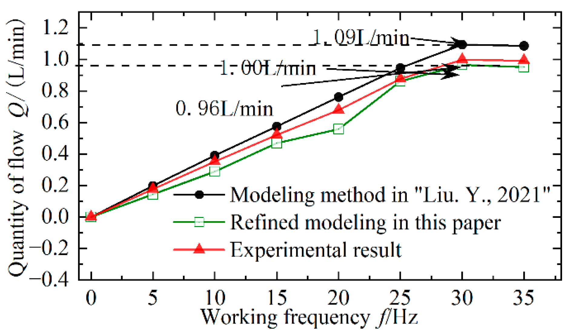
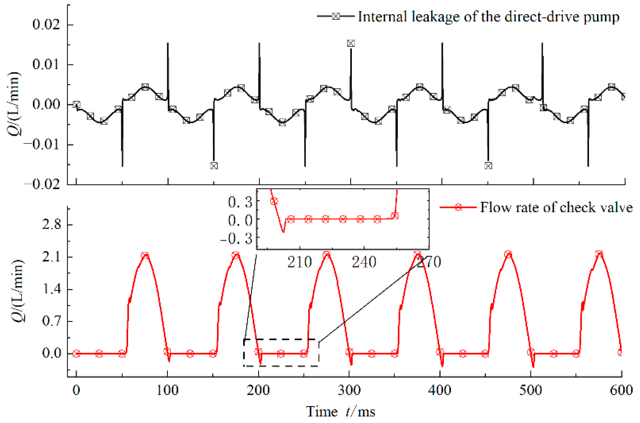
4.3. Flow Test and Analysis of Actuation System

In order to test the flow characteristics of the EDHAS at different frequencies, the piston target motion of the direct-drive pump is set as a sinusoidal curve with an amplitude of 7 mm. The average output flow of the electromagnetic direct-drive pump is obtained through simulation and experimental measurement as shown in Figure 9. In the frequency range of 0–30 Hz, the average flow rate measured by simulation and experiment is approximately proportional to the actuating frequency of the driving unit.
However, due to the inevitable mixing of air in the oil, the reduction of the bulk modulus of the liquid, the viscosity of the liquid, the temperature rising under high-frequency action, and other nonlinear time-varying limitations during the experiment, the experimental results are somewhat different from the simulation results, and the error between the experimental results and the simulation results will increase with the increase of frequency. When the frequency is greater than 30 Hz, the average flow rate begins to decrease. This is because the inevitable fluid-solid coupling effect of the passive check valve limits response speed, which intensifies the backflow of the pump at a high working frequency and leads to a decrease in the output flow rate.
Compared with the multidisciplinary modeling method proposed in reference [20], the refined modeling method proposed in this paper further considers the dynamic friction of the linear actuator, and the simulation results are more consistent with the experimental results. The error of the peak flow rate of the system is reduced from 13.5%, which is in reference [20], to 4.2% in this paper. The prediction of the changing trend of the system flow characteristics proves the effectiveness and accuracy of the refined electromechanical–hydraulic integration modeling.
Figure 10 shows the instantaneous flow of the simulated direct-drive pump with internal leakage and passive check valve at 10 Hz. It can be seen that the instantaneous flow of the pumped hydraulic oil will suddenly decrease to different degrees. At the same time, at the end of the oil delivery of the passive check valve, the spring damping of the spool and the fluid–solid coupling effect will cause lag in its response, further aggravating the backflow of the hydraulic oil. In addition, due to the fluid resistance, the lag of oil absorption and the internal leakage of the pump significantly restrict the flow condition, which further leads to the decrease of the output flow of the direct-drive pump at a higher working frequency.
Due to the fitting clearance of the plunger friction pair and the high and low pressure difference between the two ends of the piston sealing surface, the electromagnetic direct-drive piston pump has internal leakage, the electromagnetic direct-drive piston pump has internal leakage and the peak flow is less than 0.005 L/min. At the end of the pumping stroke, the instantaneous internal leakage flow suddenly changes due to the high-pressure difference between the two ends of the piston sealing surface, and the peak flow at the sudden change reaches 0.015 L/min. The internal leakage of the direct-drive pump and the backflow of the check valve significantly affect the flow characteristics and efficiency of the system, which is also an important research direction in the future.

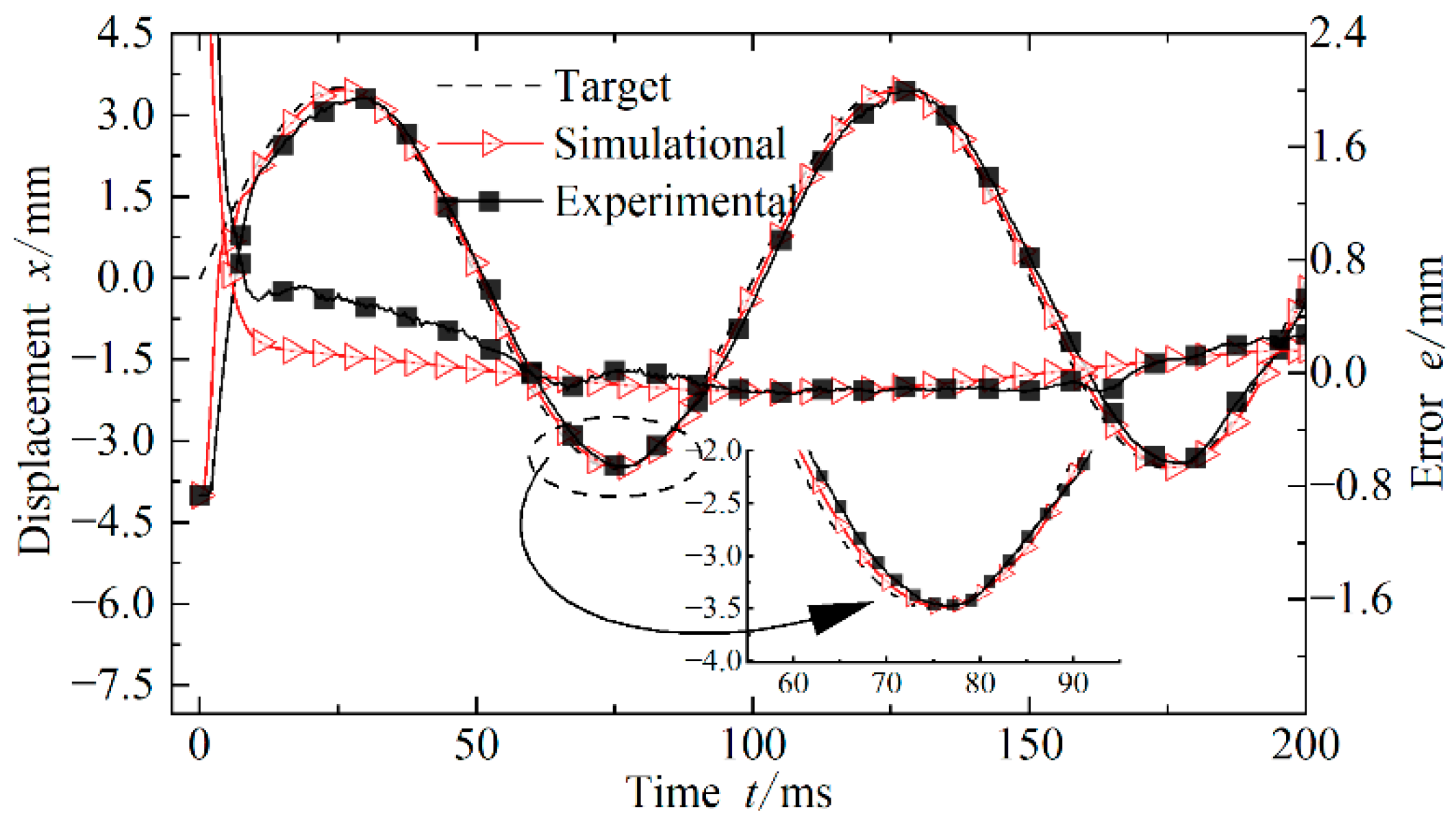
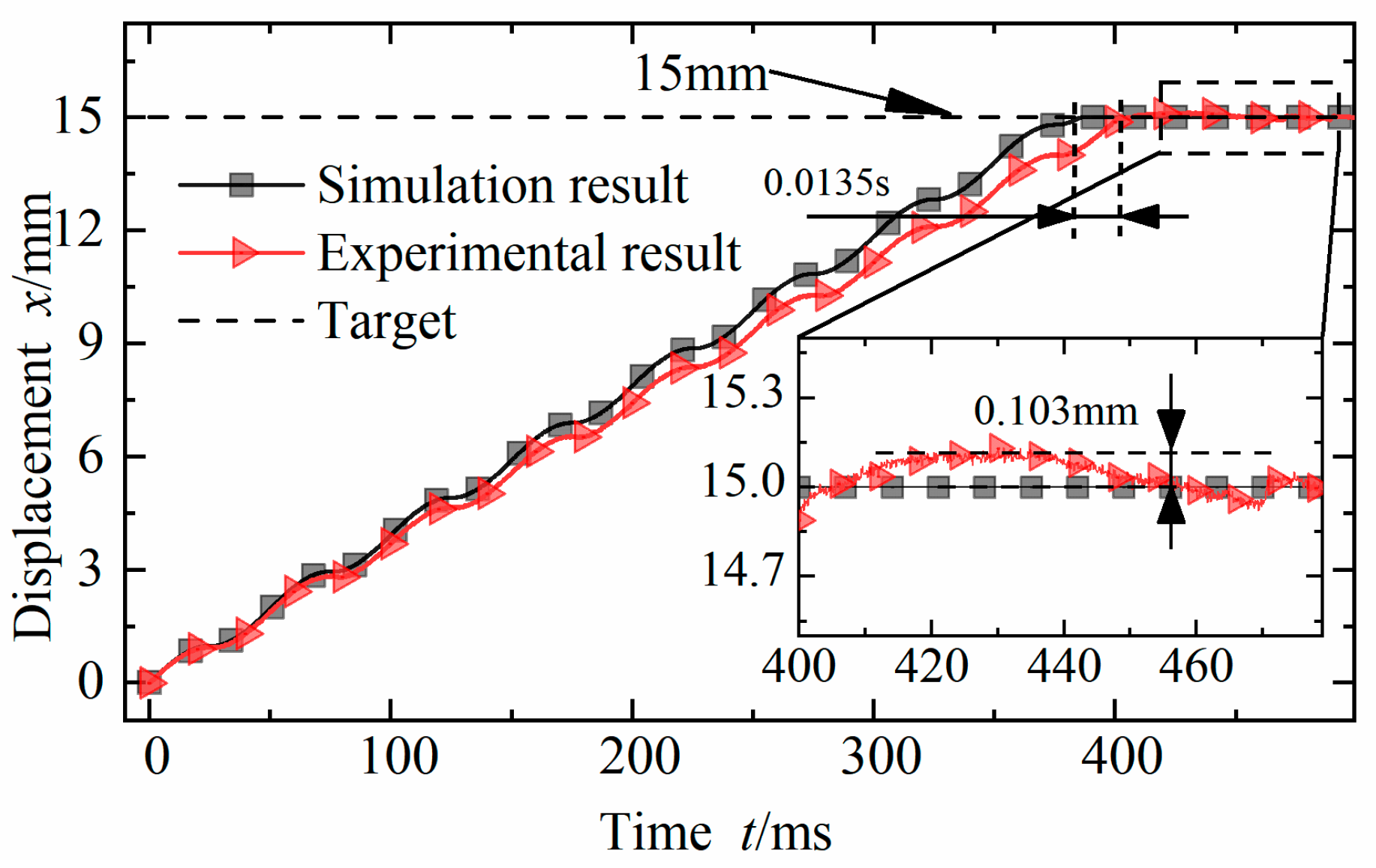
4.4. Displacement Test and Analysis of Actuator Cylinder

Figure 11 shows the simulation results and experimental results of the displacement of the electro-hydrostatic actuation system under the displacement target of 15 mm for the actuator cylinder. Both the simulated displacement response and the experimental displacement response can realize the accurate actuation of the target displacement. In the experiment, the response time of the piston rod of the hydraulic actuating cylinder is 0.392 s, and the maximum steady-state difference is 0.103 mm. The simulated response time is 0.0135 s faster than that in the experiment, and the steady-state error approaches zero. The error of the response time is 3.4%. There is a certain difference between the simulation results and the experimental results, which is due to the internal temperature rising of the system, the flow–solid coupling of the passive check valve, and other factors in the actual process. The simulation results can better predict the control performance of cylinder displacement of the electromagnetic direct-drive hydrostatic actuation system and demonstrate the effectiveness and accuracy of the refined electromechanical–hydraulic integration modeling.

5. Conclusions

(1) This paper proposes a refined electromechanical–hydraulic integration of an electromagnetic direct-drive hydrostatic actuation system considering the LuGre dynamic friction of the linear actuator, the tilting eccentric leakage of the hydraulic pump, and the Karnopp nonlinear friction of the actuating cylinder The integrated simulation model is established to provide a reference for modeling electro-hydro-hydraulic actuators based on the linear actuators.
(2) Compared with the simulation results, the peak pressure error of the system is 2.6%, the peak flow error is 4.2%, and the actuation displacement response error is 3.4%, which verifies the validity and accuracy of the refined and integrated model of the system and lays the foundation for the analysis of the characteristics and control strategy of the electromagnetic direct-drive hydrostatic actuation system.

Author Contributions

Conceptualization, methodology, validation, formal analysis, J.L., writing—original draft preparation, investigation, visualization, C.G., writing—review and editing, Y.Z., research design, C.T., data acquisition, Y.L., data analysis, C.F. All authors have read and agreed to the published version of the manuscript.

Funding

This research is supported by the National Natural Science Foundation of China (Grant No. 51905319, 51975341, 51875326), the China Postdoctoral Science Foundation (Grant No. 2021M691984), the Natural Science Foundation of Shandong Province (ZR2021QE180), the Young Technology Talent Supporting Project of Shandong Province (SDAST2021qt20), and the Zhangdian District School City Integration Development Plan (2021JSCG0015).

Data Availability Statement

Not applicable.

Conflicts of Interest

The authors declare no conflict of interest.

References

  1. Cheng, C.; Liu, S.; Wu, H. Sliding mode observer-based fractional-order proportional-integral-derivative sliding mode control for electro-hydraulic servo systems. Proc. Inst. Mech. Eng. C J. Mech. Eng. Sci. 2020, 234, 1887–1898. [Google Scholar] [CrossRef]
  2. Jiao, Z.; Kong, X.; Wang, S.; Xu, B.; He, Y.; Shang, Y. Advancements of basic researches on large aircraft of electro-hydraulic power and actuation system new architecture. China Basic Sci. 2018, 20, 41–47. [Google Scholar]
  3. Li, B.; Liu, Y.; Tan, C.; Qin, Q.; Lu, Y. Review on electro-hydrostatic actuator: System configurations, design methods and control technologies. Int. J. Mechatron. Manuf. Syst. 2020, 13, 323–346. [Google Scholar] [CrossRef]
  4. Ouyang, X.; Zhao, T.; Li, F.; Yang, S.; Zhu, Y.; Yang, H. Integral variable pi control on flow load simulator of aircraft hydraulic system. J. Zhejiang Univ. (Eng. Sci.) 2017, 51, 1111–1118. [Google Scholar]
  5. Yang, G.; Yao, J. High-precision motion servo control of double-rod electro-hydraulic actuators with exact tracking performance. ISA Trans. 2020, 103, 266–279. [Google Scholar] [CrossRef]
  6. Liu, J.; Jiang, J.; Ou, J.; Zhang, C.; Liu, Q. Theoretical model and dynamic performance of direct drive volume control electro-hydraulic servo system. J. Harbin Inst. Technol. 2011, 43, 61–65. [Google Scholar]
  7. Zhang, J.; Chao, Q.; Xu, B.; Pan, M.; Chen, Y.; Wang, Q.; Li, Y. Effect of piston-slipper assembly mass difference on the cylinder block tilt in a high-speed electro-hydrostatic actuator pump of aircraft. Int. J. Precis. Eng. Manuf. 2017, 18, 995–1003. [Google Scholar] [CrossRef]
  8. Wei, X. Research on Dual-Variable Control Algorithm of Electro-Hydrostatic Actuator; Beijing Jiaotong University: Beijing, China, 2020. [Google Scholar]
  9. Li, Y.; Jiao, Z. Study on electro hydrostatic actuation mechanism of linear drive. J. Mech. Eng. 2016, 52, 37–45. [Google Scholar] [CrossRef]
  10. Yang, X.; Zhu, Y.; Zhu, Y. Characteristic investigations on magnetic field and fluid field of a giant magnetostrictive material-based electro-hydrostatic actuator. Proc. Inst. Mech. Eng. G J. Aerosp. Eng. 2018, 232, 847–860. [Google Scholar] [CrossRef]
  11. Ren, G.; Costa, G.K.; Sepehri, N. Position control of an electro-hydrostatic asymmetric actuator operating in all quadrants. Mechatronics 2020, 67, 102344. [Google Scholar] [CrossRef]
  12. Shang, Y.; Li, X.; Qian, H.; Wu, S.; Pan, Q.; Huang, L.; Jiao, Z. A novel electro hydrostatic actuator system with energy recovery module for more electric aircraft. IEEE. Trans. Ind. Electron. 2019, 67, 2991–2999. [Google Scholar] [CrossRef]
  13. Zhang, X.; Wang, X.; Zhang, H.; Quan, L. Characteristics of wheel loader lifting device based on closed pump-controlled three-chamber hydraulic cylinder. Trans. Chin. Soc. Agric. Mach. 2019, 50, 410–418. [Google Scholar]
  14. Yu, Z.; Li, Z.H.; Liu, L. Integrated design of polynomial nonlinear modeling and control of electro-hydraulic servo systems. Contl. Theor. Appl. 2021, 38, 364–372. [Google Scholar]
  15. Padovani, D.; Ketelsen, S.; Hagen, D.; Schmidt, L. A self-contained electro-hydraulic cylinder with passive load-holding capability. Energies 2019, 12, 292. [Google Scholar] [CrossRef]
  16. Phan, V.D.; Ahn, K.K. Optimized-Based Fault-Tolerant Control of an Electro-Hydraulic System with Disturbance Rejection. Appl. Sci. 2022, 12, 9197. [Google Scholar] [CrossRef]
  17. Woongyong, L.; Jun, K.M.; Kyun, C.W. Asymptotically stable disturbance observer-based compliance control of electrohydrostatic actuators. IEEE ASME Trans. Mechatron. 2019, 25, 195–206. [Google Scholar]
  18. Ge, L.; Quan, L.; Zhang, X.; Dong, Z.; Yang, J. Power matching and energy efficiency improvement of hydraulic excavator driven with speed and displacement variable power source. Chin. J. Mech. Eng. 2019, 32, 100. [Google Scholar] [CrossRef]
  19. Xu, X.; Li, Z.; Qin, H. Design and integrated simulation of the electro-hydraulic servo system based on AMESim and Matlab. Appl. Mech. Mater. 2011, 44, 1355–1359. [Google Scholar] [CrossRef]
  20. Chao, Q.; Zhang, J.; Xu, B.; Huang, H.; Pan, M. A review of high-speed electro-hydrostatic actuator pumps in aerospace applications: Challenges and solutions. J. Mech. Des. 2019, 141, 050801. [Google Scholar] [CrossRef]
  21. Cai, Y.; Ren, G.; Song, J.; Sepehri, N. High precision position control of electro-hydrostatic actuators in the presence of parametric uncertainties and uncertain nonlinearities. Mechatronics 2020, 68, 102363. [Google Scholar] [CrossRef]
  22. Thien, T.D.; Xuan, B.D.; Kwan, A.K. Adaptive backstepping sliding mode control for equilibrium position tracking of an electrohydraulic elastic manipulator. IEEE Trans. Ind. Electron. 2019, 67, 3860–3869. [Google Scholar]
  23. Tian, X.; Wang, S.; Wang, X.; Dong, D.; Zhang, Y. Design and Control of a Compliant Electro-Hydrostatic-Powered Ankle Prosthesis. IEEE ASME Trans. Mechatron. 2021; in press. [Google Scholar] [CrossRef]
  24. Tan, C.; Li, B.; Yu, P.; Lu, J.Y.; Liu, Y.T.; Sun, Z.Y. Multidisciplinary Modeling and Optimization of Direct-Driving Electro-Hydrostatic Actuator. Trans. Beijing Inst. Technol. 2021, 1–9. [Google Scholar] [CrossRef]
  25. Ge, Y.; Zhu, W.; Liu, J. Refined Modeling and Characteristic Analysis of Electro-hydrostatic Actuator. J. Mech. Eng. 2021, 57, 66–73. [Google Scholar]
  26. Khurram, B.; Gustavo, K.C.; Nariman, S. Optimization-Driven Controller Design for a High-Performance Electro-Hydrostatic Asymmetric Actuator Operating in All Quadrants. J. Dyn. Syst. Meas. Control 2021, 143, 094503. [Google Scholar]
  27. Li, B.; Li, D.; Ge, W.; Tan, C.; Lu, J.; Song, A. Precision control of hydraulic pressure in fast-response brake-by-wire system based on direct-drive valve. China J. Highw. Transp. 2021, 34, 121–132. [Google Scholar]
  28. Lu, J.; Chang, S.; Liu, L.; Fan, X. Point-to-point motions control of an electromagnetic direct-drive gas valve. J. Mech. Sci. Technol. 2018, 32, 363–371. [Google Scholar] [CrossRef]
  29. Peng, X.; Gong, G.; Liao, X.; Wu, W.; Wang, H.; Lou, H. Modeling and Model Identification of Micro-position-control Hydraulic System. J. Mech. Eng. 2017, 53, 206–211. [Google Scholar] [CrossRef]
  30. Wang, Y.; Zhao, J.; Ding, H.; Zhang, H. Output feedback control of electro-hydraulic asymmetric cylinder system with disturbances rejection. J. Franklin Inst. 2021, 358, 1839–1859. [Google Scholar] [CrossRef]
  31. Lu, Y.; Lu, J.; Tan, C.; Tian, M.; Dong, G. Adaptive Non-Singular Terminal Sliding Mode Control Method for Electromagnetic Linear Actuator. Micromachines 2022, 13, 1294. [Google Scholar] [CrossRef]
  32. Lin, C.J.; Yau, H.T.; Tian, Y.C. Identification and compensation of nonlinear friction characteristics and precision control for a linear motor stage. IEEE ASME Trans. Mechatron. 2012, 18, 1385–1396. [Google Scholar] [CrossRef]
Figure 1. Schematic diagram of EDHAS.
Actuators 11 00281 g001
Figure 2. Schematic of inclined eccentric internal leakage.
Actuators 11 00281 g002
Figure 3. Simulation model of the DEHAS in AMESim.
Actuators 11 00281 g003
Figure 4. Simulation model of the DEHAS in Matlab/Simulink.
Actuators 11 00281 g004
Figure 5. Experimental platform of DEHAS.
Actuators 11 00281 g005
Figure 6. Friction identification results of ELA.
Actuators 11 00281 g006
Figure 7. Motion curve of the direct-drive pump piston.
Actuators 11 00281 g007
Figure 8. Pressure of direct-drive pump outlet hydraulic line.
Actuators 11 00281 g008
Figure 9. Curves of flow with different frequencies.
Actuators 11 00281 g009
Figure 10. Response curve of instantaneous flow.
Actuators 11 00281 g010
Figure 11. Response curve of step target.
Actuators 11 00281 g011
Table 1. Main parameters of DEHS [24].
 Parameter Value
 Diameter of direct-drive pump piston/mm 12
 Working stroke of direct-drive pump/mm 10
 Dead zone volume of direct-drive pump/mm3 10
 Mover mass of direct-drive pump/Kg 0.12
 Dead zone volume of actuator cylinder /mm3 10
 Diameter of actuator cylinder output rod/mm 20
 Diameter of actuator cylinder piston/mm 30
 Working stroke of actuator cylinder/mm 20
 Coil resistance of ELA/Ω 1.41
 Coil inductance of ELA/mH 1.1
 Electromagnetic force coefficient of ELA/N/A 24.61
Publisher’s Note: MDPI stays neutral with regard to jurisdictional claims in published maps and institutional affiliations.

