Abstract
A hybrid damper concept is presented here using a combination of a Magnetorheological (MR) Fluid (MRF) and Shape Memory Alloy (SMA)-based energy dissipation. A demonstration is performed utilizing the shear operating mode of the MRF and the one-way effect of the SMA. The damping performance of different MRF-SMA configurations is investigated and the corresponding energy consumption is evaluated. We demonstrate that the operation of MRF and SMA dampers complement each other, compensating for each other’s weaknesses. In particular, the slow response from the MR damper is compensated by passive SMA damping using the pseudoplastic effect of martensite reorientation, which can dissipate a significant amount of shock energy at the beginning of the shock occurrence. The MR damper compensates for the incapability of the SMA to dampen subsequent vibrations as long as the magnetic field is applied. The presented hybrid SMA-MR damper demonstrates superior performance compared to individual dampers, allowing for up to five-fold reduction in energy consumption of the MR damper alone and thereby opening up the possibility of reducing the construction volume of the MR damper.
1. Introduction
Shock dampers are crucial components deployed in a variety of applications to dissipate shock loading energy and thereby reduce subsequent oscillations. They have been applied in massive structures such as buildings and bridges, automobiles, and daily application such as doors and furniture. Many damper concepts have evolved over the past century, with hydraulic dampers emerging as the most common type of passive shock absorber [1]. Semi-active shock absorbers using magnetorheological dampers are gaining popularity in automobiles owing to their adaptive shock damping capability [2]. Active damping concepts are an option where a fast and precise response is required. The drive towards miniaturization and enhanced integration of sensors and actuators opens up novel damping applications on small scales, such as vibration compensation of motion sensors [3], optical image stabilization [4], and miniature robotics [5].
Generally, there are both advantages and limitations to the choice of either passive or active damping. Passive dampers offer design simplicity and more reliable operation than active dampers, while active dampers enable optimal vibration control for various excitations at the cost of complex control scheme designs. Moreover, device or power failure in active dampers can have a catastrophic impact. A combination of both active and passive dampers offers more reliable operation and can improve overall damping performance. The effectiveness of combining various active and passive damper concepts has previously been presented. Foshage et al. demonstrated complementary action of active and passive damper elements consisting of a voice coil motor for low-frequency vibration isolation and a passive suspension for high-frequency vibration isolation [6]. Suda et al. developed a hybrid suspension consisting of two DC motors, with one configured to operate as a passive damper and the other as an active damper element, depending on the connected load. This approach demonstrated improved vibration isolation over passive damping alone [7]. For automotive applications, various damping concepts combining passive dampers (e.g., hydraulic damping, eddy current damping) and active damping consisting of electromagnetic dampers have demonstrated improvements in shock damping performance while simultaneously achieving energy regeneration from vibrations [8,9]. Another option in this regard is to combine semi-active and passive damping. Magnetorheological (MR) fluid-based damping has the advantage of adjusting the blocking force based on the applied magnetic field [10]. Depending on the loading amplitude, SMA dampers are capable of dissipating up to 86% of the loading energy [11]. Previous research has demonstrated high damping performance for SMA damping devices under shock loading [12]. Combining a pseudoelastic Shape Memory Alloy (SMA) and MR damping has proven to be effective in reducing the frequency response over a large frequency range arising from seismic loading [13]. Furthermore, the energy dissipation is adjustable depending on the excitation of the MR damper. Pseudoelastic SMA contributes to reduced oscillation amplitude at low-frequency excitations and MR damping suppresses the oscillations at higher frequencies [14]. However, owing to the elastic energy of the pseudoelastic SMA, larger magnetic field excitation of the MR damper is essential to reduce the vibrations introduced by high amplitude shock loads.
Here, we present a shock damper concept combining an MR damper and SMA foil-based damper, showing a one-way shape memory effect that effectively suppresses both small and large amplitude shock loads. In contrast to the above-mentioned approaches using pseudoelastic SMA, the high energy dissipation of up to 86% [11] for one-way SMA in a single mechanical loading cycle enables enhanced dissipation of the shock loading energy within the first oscillation cycle after shock loading. In this way, the SMA damper predominantly dissipates energy during the first oscillation cycle and the subsequent oscillations are suppressed by MR damper. With this approach that uses the SMA damper in passive mode, there is no need to deliver a high-power heating pulse to the SMA damper device to enable phase transformation within the first oscillation cycle after shock loading.
The rest of this paper is organized as follows: in Section 2, a theoretical overview of MR fluid and SMA operation is provided. In Section 3, the design of the MR and SMA dampers is illustrated. In Section 4, the configurations of the test rig, loading conditions, and shock response of the hybrid damper are presented. The results are evaluated and summarized in the last chapter, followed by our conclusions and prospects for future research.
2. Theoretical Background
2.1. Magnetorheological Fluid
Magnetorheological fluids are substances with rheological behavior that can change over a wide range under the influence of magnetic fields. The rheological behavior of a fluid material is determined by its physical qualities, namely, shear stress and shear rate . For magnetorheological fluids, these two physical quantities are related as follows:
following the classical Bingham model. In this relation, is the dynamic viscosity and is the yield stress due to the influence of the applied magnetic field B.
In this work, the magnetorheological fluid AMT-SMARTEC+ from Arus MR Tech is used. Its properties are listed in Table 1.

Table 1.
Physical properties of the magnetorheological fluid AMT-SMARTEC [15].
The relationship between the applied magnetic field density B (in T) and the generated MR fluid yield stress (in kPa) can be found in the datasheet of the [15] fluid, where the yield stress
is a third order polynomial function of the applied magnetic field.
2.2. Shape Memory Alloy (SMA)
The unusual behavior of SMA materials is attributed to their underlying phase transformation behavior between the martensite and austenite phases. Depending on the operating temperature, SMA materials exhibit either pseudoelasticity or a one-way shape memory effect. Operating temperatures above the austenite finish temperature (Af) induce pseudoelasticity, while those below the martensite finish temperature (Mf) result in a one-way shape memory effect. In pseudoelastic SMA, the stress-induced phase transformation between the starting austenite phase and the martensite phase results in pseudoelastic deformation upon loading and strain recovery. For a one-way SMA, in the absence of mechanical load, the material exists in the martensite phase below Mf and in the austenite phase above Af.
Figure 1 illustrates the one-way shape memory effect using a qualitative stress-strain-temperature plot (--T). At ambient temperature under stress-free conditions (, = 0), the material is in the unoriented martensite state (UM), usually consisting of several martensite variants that self-accommodate to minimize strain energy. Reorientation of martensite initiates above the critical loading stress. Thereafter, the material undergoes a large deformation strain until the completion of martensite orientation. Upon unloading, most of the material deformation is retained. In this cyclic mechanical loading, a large portion of the loading energy is dissipated (). Subsequent thermal loading of the material is necessary for strain recovery. On heating above Af, the material transforms to austenite. The material returns to the UM state upon cooling below Mf. Owing to the high energy dissipation of one-way SMA under passive operation (i.e., without application of heating pulse) attributed to the pseudoplastic effect of martensite reorientation, this material is used here to develop our proposed hybrid damper.
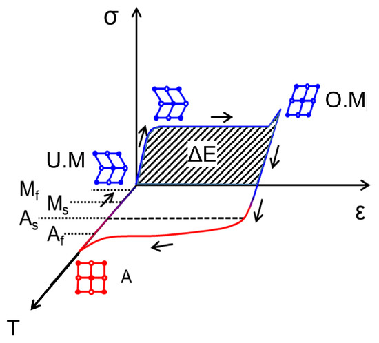
Figure 1.
Illustration of phase transformation for one-way shape memory material.
3. Design of the Hybrid Damper
In this section, the configuration of the test setup is elaborated. Each utilized damper element and their combination in a shock loading setup is explained individually.
3.1. Experimental Setup Configuration
Figure 2 shows the complete test setup where the SMA and MR dampers are integrated. The physical properties of the dampers and system are consolidated in Table 2.

Figure 2.
Experimental setup for investigating the proposed hybrid damper concept in dissipating the energy from shock loading.

Table 2.
Parameters of each damper element and the vibratory system in the experimental setup.
The test system consists of a mass of m = 2.53 kg connected to four springs with a total stiffness of (6.25 kN/m on each spring). This results in a characteristic time () of 62 ms for the oscillating system. The movement of the mass is guided along the x-direction using linear guides. The SMA bridges and MR damper are attached to the mass in parallel. Each end of SMA bridge is clamped between two blocks of Plexiglas. The shock loading is introduced using an electromagnet, which is installed on the right side of the mass at an initial distance of d. In this way, the exact same loading can be used repeatedly in the test system. The movement of the mass itself is then tracked using an OFV-3001 laser vibrometer from Polytec. The force of the MR damper is varied by changing the applied current. For the SMA, its state is initialized by a current pulse. Therefore, the SMA is connected to a current source and the current pulse is regulated by the control system. By analyzing the displacement of the mass for various damper states, the damping behavior of the hybrid concept can be investigated. An ADwin Pro-II is used to conduct both actuation and data acquisition in real time. A schematic of the test setup is shown in Figure 3.
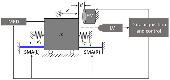
Figure 3.
Schematic of SMA-MR damper system test setup with vibrational system . Legend: m—Mass, EM—Electromagnet, LV—Laser vibrometer, MRD—MR damper, SMA (L,R)—SMA damper (left, right), —spring constants, l—unstrained length of the SMA damper device.
3.2. Magnetorheological Fluid-Based Damper
The magnetorheological fluid damper used for this investigation has a special feature. The construction is designed such that the damping force in the absence of the magnetic field is significantly lower than a conventional construction. This is achieved by using a special MR damper design in which the MR fluid is contained in a porous medium. Figure 4 shows the design of the constructed MR damper. As can be seen in the figure, the damper consists of an electromagnet (the configuration of the magnetic circuit is shown in the right figure), a fluid chamber, and a shear plate connected to linear guides. The electromagnet is separated from the shear plate to minimize the moving mass. In our first investigation, the iron core is constructed from three iron blocks. The geometry parameters of the MR damper are listed in Table 2.
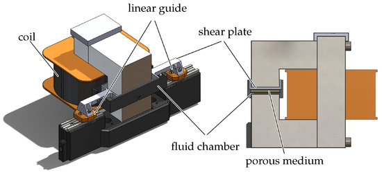
Figure 4.
Design of the MR damper (left) and a cut section showing the magnetic circuit (right).
The MR damper uses the shear operating mode. The shear plate is intentionally installed with a gap of 0.5 mm to the surface of the porous medium, as shown in Figure 5.
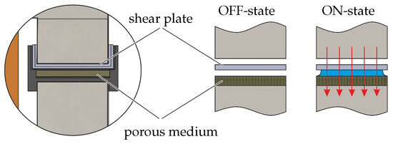
Figure 5.
Working principle of the MR damper utilized in this work, with a porous medium as the fluid container.
In this way, when no magnetic field is applied (OFF-state) there is no contact between the shearing plate and the porous medium. This configuration results in a small frictional force in the OFF-state, with the only friction caused by mechanical contact with the linear guides. In the ON-state, when the magnetic field is applied, the contained MR fluid draws away from the porous medium and contacts the surface of the shear plate. As the shear plate moves, a damping force is generated, the magnitude of which depends on the plate’s movement velocity and the magnitude of the magnetic field applied within the fluid chamber. The measured damping force of the damper’s velocity characteristic of the MR damper is presented in Figure 6. It can be seen in this figure that there is an increment of the total damping force when a magnetic field (current) is applied. The force offset in the OFF-state () comes from the friction of the linear guides, which have a magnitude of 0.8 N. This friction force is much smaller than conventional MR dampers, thanks to configuration with a porous medium that is used in thie proposed setup.
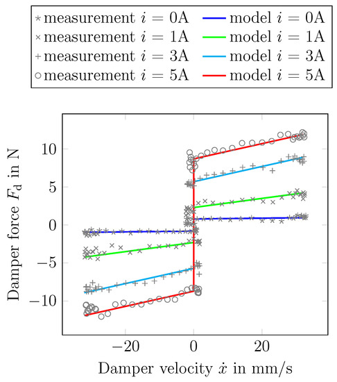
Figure 6.
Comparison between the measured and modeled force-velocity characteristic line of the MR damper.
As in [16], using the shear operating mode of an MR fluid-based damper, Equation (1) can be transformed using the mechanical factors (operating area and gap width) into the relation between the damping force , the damper’s velocity , and the current i, as follows:
Due to the existence of frictional force from the guides, the total force from the damper is then
As a result of the special design of the MR damper, the gradient of the force-velocity characteristic line (the damping constant d) is a function of the magnetic field. For the damper used in this work, the following functions
are used to obtain the value of the damping constant d (in Ns/m) and the yield force (in N) based on the applied current i in A.
The shear mode of the damper only requires a shear plate with a dimension of 50 mm × 30 mm, as listed in Table 2. However, the construction volume of the MR damper is quite large. This is due to the iron core and the coil used to generate the required magnetic field. Therefore, it is important to reduce the force requirement in the system to permit a smaller coil and iron core of the electromagnet.
3.3. Shape Memory Alloy
Starting from a 30 μm-thick cold-rolled Ni49.82Ti50.18 foil, the phase transformation temperatures are adjusted by heat treatment at 450 °C for 30 min to show a one-way effect at room temperature. Figure 7 shows Differential Scanning Calorimetry (DSC) measurements illustrating the phase transformation behaviour of this foil. The material undergoes one-stage transformation to austenite during heating and two-stage transformation from austenite to martensite through an intermediate R phase. The transformation temperatures can be determined as follows: As = 47.2, Ap = 54.2, Af = 59.1, Rp = 47.9, Ms = 2, Mp = −5.09 °C, Mf = −28.5 °C. The latent heat associated with the transformation from martensite to austenite (LMA) is determined from the area enclosed by the transformation peak as 18.62 J/g. Even though the material is not entirely in the martensite state when it is at room temperature and in a stress-free situation, no visible influence in term of its mechanical loading behaviour is observed. Usually, the effect of the R-phase is observed as a small plateau at low loading strains of about 0.5%. In this material, this behaviour is observed only in the first training cycle. Therefore, the effect of the R-phase is not further discussed here.
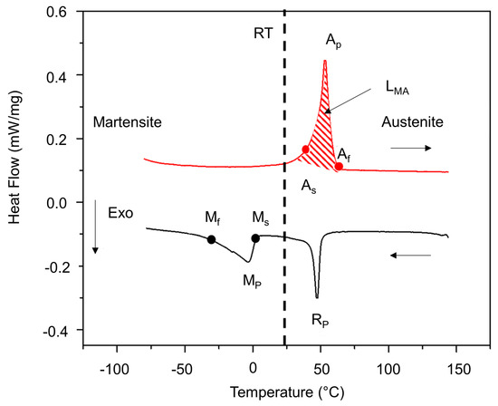
Figure 7.
DSC measurement showing phase transformation of NiTi SMA material.
The SMA bridge damper devices used in this research are shown in Figure 8a. The force-displacement characteristic of this device under uniaxial tensile loading is shown in Figure 8b.
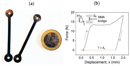
Figure 8.
Picture of SMA bridge damper (a) and the damper’s mechanical behaviour under tensile loading (b).
The device requires a critical force of about 14 N to initiate martensite reorientation. It is designed for a maximum shock loading amplitude of 2 mm, under which the maximum strain reaches 5%. This device has a stiffness of 28 N/m in the unoriented martensite state. The major design parameters of the SMA damper device are the length and width of the SMA bridge. Here, a length of 40 mm is used for the SMA bridges in order to limit the loading strain to 5% under the maximum shock loading of 2 mm. The width of the SMA bridge is a critical design parameter that determines the energy dissipation under shock loading. Maximum energy dissipation via material hysteresis is the key to obtaining high shock damping performance. External springs are used in this shock damper test setup, introducing an effective stiffness of . By designing the width of the SMA bridge device, the critical force required for martensite reorientation is adjusted to ensure that the first oscillation after shock loading utilizes maximal hysteresis. Another aspect to be considered in the width design is the range of the applied shock loading amplitude. A minimum shock loading amplitude of 1.5 mm is considered for our proposed design, which corresponds to a strain of 3.75%. Assuming that the first oscillation after shock loading of 1.5 mm has an amplitude up to 0.75 mm, the maximum force exerted by the external springs is 18.75 N. The width of the SMA damper device has to be designed to adjust the critical force below the maximum spring force during the first oscillation. Therefore, a width of 3 mm is chosen to achieve a critical force of 14 N, enabling sufficient energy dissipation for shock loading from 1.5 mm.
4. Experiments and Measurement Results
In this section, the experimental procedure and its results are elaborated. The first experiments focus on finding the best configuration for the damper in order to suppress the vibrations arising from shock loading. The resulting best configuration is then investigated under various shock loads.
4.1. Experimental Procedure
Shock excitation mathematically corresponds to an impacting force acting on the vibrational system . This is ideally represented by the initial conditions . Experimentally easier to realize and more reproducible, however, is an initial displacement . For this loading, shock behavior can be interpreted at the time instant of the first zero-crossing of the displacement. Thus, it is appropriate to carry out experimental investigations under initial displacement excitation.
We conduct our investigation based on the aforementioned case as follows. First, the shock load is introduced to the test system by activating the electromagnet, whereby the vibrational system is pulled away from its steady state position. Upon deactivation of the electromagnet, the mass starts to oscillate. The free oscillation behaviour of the system after shock loading is analysed to estimate the effectiveness of the SMA-MR damper. The effectiveness of the damper is evaluated by how quickly the vibration caused by the shock loading can be suppressed.
The operation cycle of this experiment is illustrated in Figure 9. Initially, the mass is kept at a distance of d from the electromagnet (a). The shock loading is provided by activating the electromagnet (b), whereby the mass is pulled, with an initial displacement of d. Under this condition, the SMA (L) together with springs on the left side is elongated by the displacement d. At the other side of the mass, the SMA (R) undergoes buckling owing to lack of compressive stress in the foil. The springs on the right side are compressed. When the electromagnet is deactivated, the mass begins to oscillate about the initial neutral position. The MR damper is activated at the same time instant when the electromagnet is deactivated. When the mass reaches the neutral position for the first time (c), the SMA (L) undergoes buckling owing to the residual strain after shock loading. The mass movement starting from this neutral position in the negative x-direction results in loading of the SMA (R) until , as shown in (d). When the mass reaches the neutral position for the second time, both SMA devices are in buckled condition (e) owing to the residual strain. Thereafter, the SMA bridges do not take part in further dissipation. However, the SMA bridges contribute to energy dissipation in this first cycle through martensite reorientation (see Figure 1) starting from the beginning of the shock occurrence. The SMA undergoes shape recovery and returns to its neutral state (a) when a heating pulse is applied.
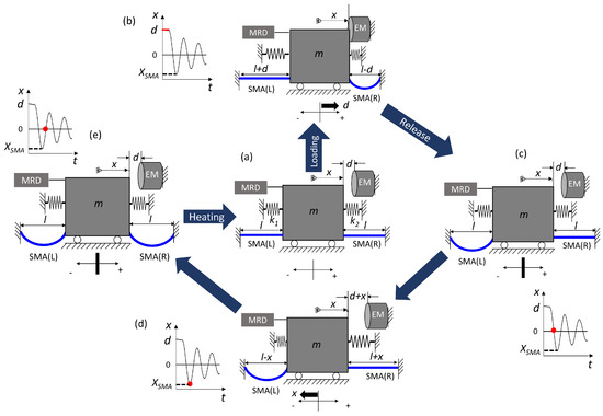
Figure 9.
Illustration of operation cycle of experimental setup.
The MR damper, on the other hand, undergoes a delay before its activation. Starting from the time it is activated (at the instant of mass release from the electromagnet), it takes several tens of milliseconds to generate the magnetic field and therefore attain its steady-state damping force. Nevertheless, it is always able to dissipate the energy as long as the magnetic field is applied.
Combining the effects of SMA and MR damping through a tandem operation forms the basis of this hybrid damper concept. In addition, depending on the dissipation provided by the SMA bridge, there exists a possibility of miniaturizing the size of the MR damper even further.
4.2. Identification of Best Damper Configuration
An overview of test configurations investigated in this research is shown in Figure 10. The initial test focuses on identifying the best damper configuration among four configurations, named ‘Config. A to D’, based on their suppression of free oscillations after shock loading. The shock damping performance of the MR damper alone is studied as ‘Config. A’. The effect of the MR combined with SMA damper devices at both sides of the mass is investigated as ‘Config B’. The contribution of the left and right side SMA damper are individually studied as ‘Config. C’ and ‘Config. D’, respectively.
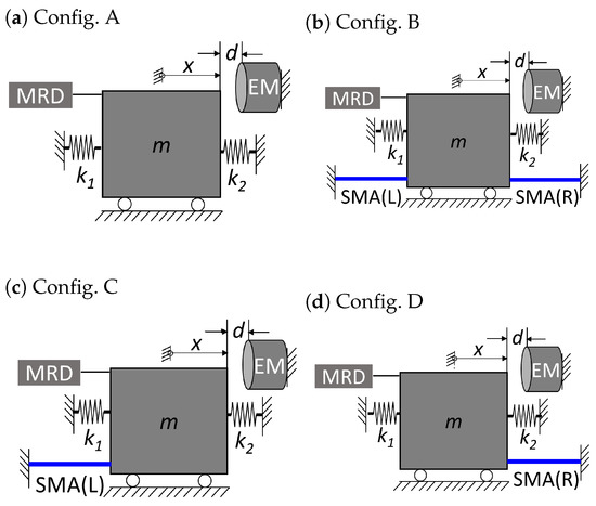
Figure 10.
Various test configurations of the experimental setup.
4.2.1. Magnetorheological Damper
The individual damping performance of the MR damper for various current excitations is investigated using ‘Config. A’ to establish a benchmark for further comparison. The response to a shock load amplitude of 1.5 mm is shown in Figure 11. The mass is released at time instant . A latency in mass release is observed due to the residual magnetization in the electromagnet. Without current excitation, the shock loading energy is predominantly dissipated by the viscous friction of the MR damper. The MR damper is then activated at by applying a current to the magnet’s coil. With increasing current, the damping force of the MR damper is increased, reducing the oscillation amplitude and settling time. The first overshoot amplitude reduction is not influenced by the increase in MR damper excitation above 3 A. The magnetic field measurement from the MR damper indicates that a time period of up to 100 ms is required in order to attain its steady state damping behaviour after activation. This suggests that the overshoot amplitude is not reduced any further when the oscillation is within the activation time constant of the MR damper. The second overshoot amplitude is more distinctly reduced by the increase in current excitation. For excitations above 3 A, the oscillations settle down after one oscillation. The current excitation of 3 A is therefore considered as a benchmark excitation for all the remaining shock loading measurements at 1.5 mm.
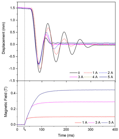
Figure 11.
The mass displacement behaviour and the generated magnetic field in the MR damper with time at various current excitations based on ‘Config. A’.
4.2.2. SMA Damper
The effect of the SMA damper alone on shock damping is estimated using ‘Config. A’ and ‘Config. B’. Here, the MR damper is not electrically activated. The resulting system response is shown in Figure 12. By inserting the SMA dampers SMA (R) and SMA (L), the oscillation amplitudes is reduced owing to the energy dissipated by the SMA damper. There is a slight increase in the stiffness of the system due to the presence of the SMA damper. The number of oscillations before the vibrational system settles down remains almost identical for both configurations. This implies that the SMA damper is not effective in damping the oscillations from the second overshoot due to the buckling of the SMA damper device.
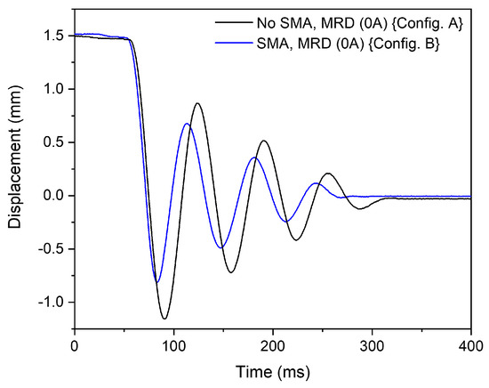
Figure 12.
The displacement behaviour of mass with time showing the effect of SMA on shock damping based on ‘Config. B’.
- Heating Pulse:
Thus far, SMA damper is used only in passive mode during shock loading. The impact of phase transformation to austenite upon application of a heating pulse to the SMA damper is investigated using ‘Config. B’, and is shown in Figure 13. A heating pulse of 3.3 W for 300 ms is applied at upon mass release from the electromagnet. At this heating pulse, the maximum temperature exerted on the SMA damper rises to 80 C, meaning that more than 90% of the bridge is above the austenite finishing temperature of 59 C. The SMA device is expected to generate a high recovery force at this point due to the phase transformation, which could potentially reduce the oscillation amplitude and improve the settling time. However, it is observed in this experiment that the heating pulse does not improve the damping behavior. Apparently, 300 ms is too long a pulse duration to initiate the effect of he phase transformation within the first few oscillations. A further increase in the heating current to enable phase transformation does not seem to be a viable approach for this combinational SMA-MR damper, as the target is to reduce the current requirement. Therefore, material dissipation using the martensite orientation alone is available for the damping of shock loading energy. However, a heating pulse is inevitable to enable strain recovery in the SMA damper (see Figure 9). This adds to the total energy consumption of the hybrid damper. Here, the phase transformation to austenite is achieved using a slower current pulse of 1 s at 1.2 A after shock loading.
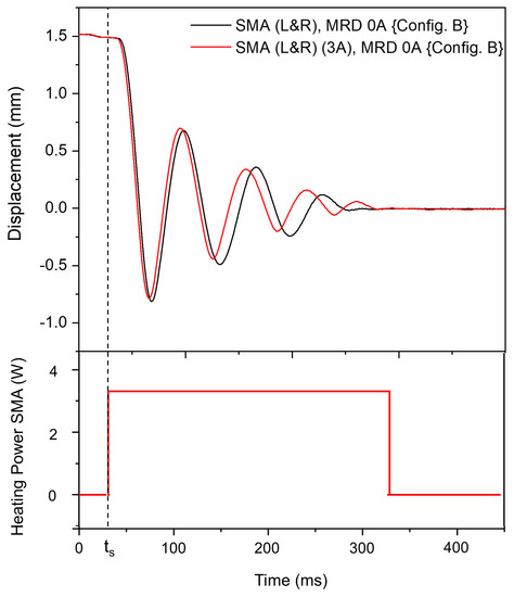
Figure 13.
The displacement behaviour of the mass when a heating pulse is applied on the SMA damper.
- SMA Position:
The contribution of the individual SMA dampers on the overall damping behaviour is studied using ‘Configs. B,C,D’, as shown in Figure 14. In ‘Config. C’, with an SMA damper on the left side, enhanced oscillation amplitudes are observed. In this configuration, the SMA damper device is already deformed during shock loading. It remains in a buckled state after the release of the mass from the electromagnet. Therefore, the left SMD does not contribute to energy dissipation. Among ‘Config. B’ and ‘Config. D’, ‘Config. D’ shows slightly better dissipation than ‘Config. B’. The elastic recovery of the left SMA damper in ‘Config. B’ results in slightly higher oscillation amplitude for this configuration. From this study, it can be inferred that ‘Config. D’ allows for maximal energy dissipation.
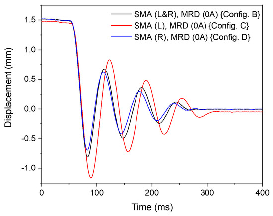
Figure 14.
The mass displacement behaviour illustrating the effect of SMA devices on the right and left sides.
- Identification of Best Operating Conditions:
From the above-mentioned test conditions, the best configuration for the individual SMA and MR dampers can be identified. For the MR damper at 3A activation, a comparable settling behaviour to 5A activation in terms of oscillation number is demonstrated before it enters its steady state position. The SMA damper shows its best performance in the absence of a heating pulse and with a single SMA bridge on the right side of the mass (‘Config. D’). Therefore, the best configuration for the combined SMA-MR damper is ‘Config. D’ with 3A activation for the MR damper.
4.3. Hybrid Damper Configuration
Based on the above investigations, the best configuration for the hybrid concept is found by combining both SMA and MR dampers and having the SMA on the right-hand side of the mass. This corresponds to the side in which the mass is being pushed during loading. Therefore, the shock damping performance of the combined SMA-MR damper is analyzed here only using ‘Config. D’ starting from this point. The performance improvement for the shock loading of 1.5 mm is shown in Figure 15.
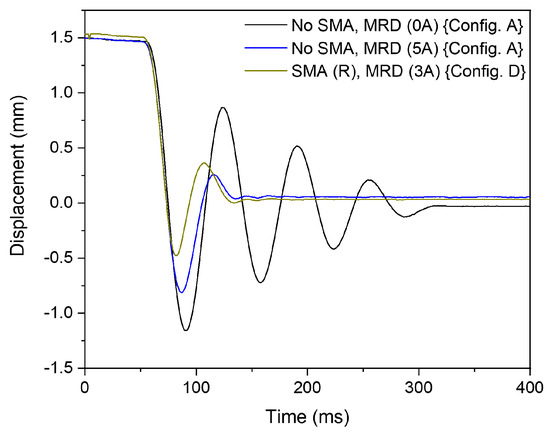
Figure 15.
The mass displacement versus time allowing for the comparison of shock damping performance of individual SMA and MR dampers and combined SMA-MR damper.
It can be seen in this figure that the performance of the MR damper alone activated at 5 A results in a significant reduction of the oscillation in comparison to the case when the MR damper is not excited. The hybrid SMA-MR damper with an SMA bridge installed and the MR damper excited by a current of 3 A demonstrates a comparable settling time with a further reduction in the amplitude of the first overshoot. This implies that the SMA damper effectively reduces the first overshoot amplitude. In addition, less current is required on the MR damper to achieve similar results, enabling further miniaturization of MR damper without affecting the performance of the hybrid damper.
The free oscillation behavior when using ‘Config. D’ confirms that the strengths of the individual dampers are effectively utilized in the hybrid damper, achieving improved reduction in first overshoot amplitude and suppression of subsequent oscillations after the second overshoot. This means that the hybrid concept is able to both improve performance and reduce the required input.
4.4. Trend in Damping Performance with Shock Load of 2 mm
To determine the trend of SMA-MR damping behaviour, a shock load of 2 mm is applied. The system response is illustrated in Figure 16. Evidently, ‘Config. D’ shows significant reduction in oscillation amplitude and settling time. By increasing the shock loading amplitude, the SMA damper can be loaded to a higher deformation strain, thereby dissipating more energy within the loading cycle. This implies that the excitation of the MR damper can be further reduced at this shock load condition.
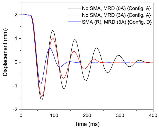
Figure 16.
The displacement behaviour with respect to time showing the effect of hybrid SMA-MR damper (‘Config. D’) and MR damper (‘Config. A’) at a loading amplitude of 2 mm.
The current excitation of the MR damper is further reduced to 2 A and the corresponding shock damping performance is analysed in Figure 17. The oscillations with an MR damper excitation of 2 A has a similar settling time as ‘Config. A’ with 5 A excitation. Yet, ‘Config. D’ has reduced oscillation amplitudes compared to ‘Config. A’. The SMA-MR damper demonstrates better damping performance and reduces the MRF damper excitation current by 60% (3 A).
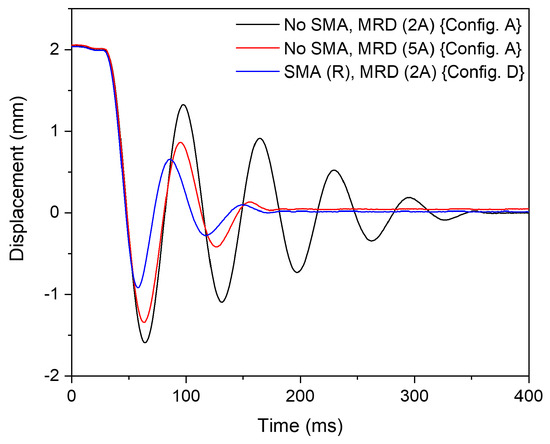
Figure 17.
The displacement behaviour versus time demonstrating the effect of hybrid SMA-MR damper (‘Config. D’) and MR damper (‘Config. A’) for a loading of 2 mm.
The energy consumption of the MR damper is expressed as
where I is the applied current, R is the resistance offered by the MR damper, and t is the time duration of the applied excitation. Assuming that the resistance of the MR damper remains constant at various current excitations, the percentage reduction in energy consumption of the MR damper is estimated using
Accordingly, a reduction in energy consumption by is achieved for the MR damper, as the excitation current requirement is reduced from 5 A to 2 A.
4.5. The Extent of Downscaling
The interesting question now arises of the amount to which the current excitation of the MR damper can be reduced while retaining improved damping performance. As observed from the trend in damping behaviour with respect to shock loading amplitude, the maximum reduction in current excitation should be achieved under the maximum shock loading amplitude allowed by the damper design, which is 2 mm for the SMA damper. In this case, the SMA damper is loaded by about 0.9 mm, as observed in the first overshoot amplitude in Figure 17 (blue line). When further increasing the shock loading amplitude to 3.6 mm, the SMA damper is loaded to 2 mm. The corresponding system response is shown in Figure 18.
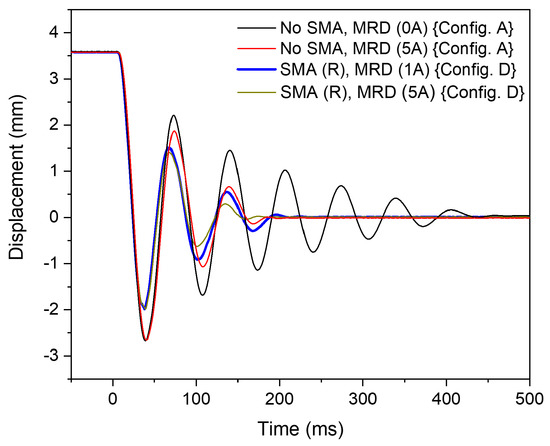
Figure 18.
The displacement behaviour with respect to time allowing for the comparison of damping performance of hybrid SMA-MR damper (‘Config. D’) with the MR damper (‘Config. A’) for a loading amplitude of 3.6 mm utilizing the maximal energy dissipation of the SMA device.
The first overshoot amplitude of the oscillation (in negative displacement) shows the loading of the SMA (R) by 2 mm. The settling behaviour shows comparable performance for the MR damper activated individually with 5 A and the combined SMA-MR damper activated with 1 A. Thus, we are able to obtain a 96% reduction in energy consumption () for the MR damper by reducing the excitation current from 5 A to 1 A. This proves that a higher loading amplitude improves the energy dissipation from the SMA. It is noteworthy that the MR-SMA hybrid damper (‘Config. D’) with 5 A MR damper activation shows only a slight improvement in damping performance.
4.6. Summary
For a better overview, the reduced energy consumption of the MR damper based on various loadings is listed in Table 3.

Table 3.
Achieved energy reduction of MR damper in combination with SMA under various loading conditions.
As can be seen in the above table, the shock loading amplitude d results in the SMA loading amplitudes in the first overshoot (see Figure 9). The SMA damper contributes to the dissipation during the first overshoot, as mentioned in Section 4.1. By increasing the SMA loading amplitude, more energy is dissipated in the first cycle of oscillation, resulting in the reduction of the excitation current of the MR damper. This equivalent current, represented as in the above table, is the excitation current that is needed to achieve a similar damping performance from the MR damper with 5 A excitation current (see Figure 11). With the maximum loading of 2.0 mm for the SMA, the MR damper requires an excitation current of only 1 A, thereby achieving a of 96% for the MR damper. Using this hybrid configuration, the MR damper can be used to reduce the subsequent vibrations after energy dissipation by the SMA. This indicates the potential of miniaturizing the MR damper in real applications.
It should be noted that real shock loading has a direction opposite to the initial velocity considered in this experimental setup (see Section 4.1). Therefore, in order to use this hybrid concept in real application, the SMA needs to be placed on the other side of the mass (on the side from where the shock comes). In this way, dissipation by the SMA begins immediately at the instant of shock occurrence.
5. Conclusions
In this work, a hybrid damper concept combining an MRF damper and an SMA damper is proposed and verified experimentally. The combination of these two dampers demonstrates complementary operation, with each covering the other’s weaknesses. The delay of the MR damper is addressed by the passive damping effect of the SMA, which is able to dissipate a significant amount of the shock energy starting from the instant of shock occurrence. The inability of the SMA to continuously dampen the subsequent vibration is taken care of by the MR damper, which is able to dissipate the energy as long as a magnetic field is applied. As a result, the SMA can be used in wider application, while the energy consumption of the MR damper can be reduced. The energy needed for the MR damper decreases with increasing shock loading amplitudes, showing improved settling behavior owing to enhanced energy dissipation by the SMA damper. A reduction of up to 96% in energy consumption is achieved for the MR damper, as the current excitation requirement can be reduced from 5 A to 1 A. This mutual integration concept in a hybrid form opens up the possibility of reducing the MR damper’s construction volume, allowing this hybrid damper concept to be applied in a miniature small vibration damping system.
In potential further investigations, the hybrid configuration proposed in this work could be used to design a new damper in which MRF and SMA dampers are integrated into one structure. The dimensions of the SMA can be adjusted based on the shock loading requirements. Furthermore, laminated iron sheets can be used to replace the iron blocks to reduce the eddy current effect and thereby improve the reaction time of the MR damper. It is to be noted that this improved reaction time when replacing the iron block with laminated iron sheets does not eliminate the delay that the MR damper possesses due to the coil inductance. Therefore, this will not change the fact that the dissipation from the SMA is beneficial in the proposed combination. Moreover, a further reduction in the construction volume of the MR damper is to be expected.
Author Contributions
All authors contributed to the conceptualization and methodology. The experimental investigation, data curation and writing are performed by K.J. and A.S.T. The supervision, review and editing are done by M.K. and T.S. All authors have read and agreed to the published version of the manuscript.
Funding
This research is funded by German Research Foundation Deutsche Forschungsgemeinschaft (DFG).
Data Availability Statement
Not applicable.
Acknowledgments
The authors would like to express their gratitude towards the German Research Foundation Deutsche Forschungsgemeinschaft (DFG) for financial support within the priority program SPP 1897, “Calm, Smooth, and Smart”.
Conflicts of Interest
The authors declare no conflict of interest.
References
- Dixon, J.C. The Shock Absorber Handbook; John Wiley & Sons: Hoboken, NJ, USA, 2008. [Google Scholar]
- Tu, F.; Yang, Q.; He, C.; Wang, L. Experimental study and design on automobile suspension made of magneto-rheological damper. Energy Proc. 2012, 16, 417–425. [Google Scholar] [CrossRef]
- Kurazume, R.; Hirose, S. Development of image stabilization system for remote operation of walking robots. In Proceedings of the 2000 ICRA, Millennium Conference, IEEE International Conference on Robotics and Automation, Symposia Proceedings (Cat. No. 00CH37065), San Francisco, CA, USA, 24–28 April 2000; Volume 2, pp. 1856–1861. [Google Scholar]
- Kazi, A.; Honold, M.; Rimkus, W.; Lokner, T.; Baeuml, M.; Koepfer, M. SMA actuator for optical image stabilization. In Proceedings of the ACTUATOR 2018, 16th International Conference on New Actuators, Bremen, Germany, 25–27 June 2018; pp. 1–4. [Google Scholar]
- Hamaguchi, M. Damping and Transfer Control System with Parallel Linkage Mechanism-Based Active Vibration Reducer for Omnidirectional Wheeled Robots. IEEE/ASME Trans. Mechatron. 2018, 23, 2424–2435. [Google Scholar] [CrossRef]
- Foshage, G.K.; Davis, T.; Sullivan, J.M.; Hoffman, T.; Das, A. Hybrid active/passive actuator for spacecraft vibration isolation and suppression. In Proceedings of the Actuator Technology and Applications, International Society for Optics and Photonics, Denver, CO, USA, 4–9 August 1996; Volume 2865, pp. 104–122. [Google Scholar]
- Suda, Y.; Nakadai, S.; Nakano, K. Hybrid suspension system with skyhook control and energy regeneration (development of self-powered active suspension). Veh. Syst. Dyn. 1998, 29, 619–634. [Google Scholar] [CrossRef]
- Martins, I.; Esteves, M.; Da Silva, F.P.; Verdelho, P. Electromagnetic hybrid active-passive vehicle suspension system. In Proceedings of the 1999 IEEE 49th Vehicular Technology Conference (Cat. No. 99CH36363), Houston, TX, USA, 16–20 May 1999; Volume 3, pp. 2273–2277. [Google Scholar]
- Ebrahimi, B. Development of Hybrid Electromagnetic Dampers for Vehicle Suspension Systems. Ph.D. Thesis, University of Waterloo, Waterloo, ON, Canada, 2019. [Google Scholar]
- Olabi, A.G.; Grunwald, A. Design and application of magneto-rheological fluid. Mater. Des. 2007, 28, 2658–2664. [Google Scholar] [CrossRef]
- Jacob, K.; Sessner, V.; Miyazaki, S.; Kohl, M. Active Vibration Damping and Control using SMA Foil-based Devices. In Proceedings of the ACTUATOR, International Conference and Exhibition on New Actuator Systems and Applications 2021, Online, 17–19 February 2021; pp. 1–4. [Google Scholar]
- Jacob, K.; Ahmadi, S.; Wendler, F.; Miyazaki, S.; Gueltig, M.; Kohl, M. Shape Memory Foil-Based Active Micro Damping for Portable Applications. In Proceedings of the 2019 20th International Conference on Solid-State Sensors, Actuators and Microsystems & Eurosensors XXXIII (TRANSDUCERS & EUROSENSORS XXXIII), Berlin, Germany, 23–27 June 2019; pp. 590–593. [Google Scholar]
- Zareie, S.; Alam, M.S.; Seethaler, R.J.; Zabihollah, A. Stability control of a novel frame integrated with an SMA-MRF control system for marine structural applications based on the frequency analysis. Appl. Ocean Res. 2020, 97, 102091. [Google Scholar] [CrossRef]
- Zareie, S.; Hamidia, M.; Zabihollah, A.; Ahmad, R.; Dolatshahi, K.M. Design, validation, and application of a hybrid shape memory alloy-magnetorheological fluid-based core bracing system under tension and compression. Structures 2022, 35, 1151–1161. [Google Scholar] [CrossRef]
- Arus MR Tech Pvt Ltd. AMT-SMARTEC. 2021. Available online: https://arusmrtech.com/product/amt-smartec/ (accessed on 17 June 2022).
- Janocha, H. (Ed.) Adaptronics and Smart Structures, 2nd ed.; Springer: Berlin, Germany, 2007. [Google Scholar]
Publisher’s Note: MDPI stays neutral with regard to jurisdictional claims in published maps and institutional affiliations. |
© 2022 by the authors. Licensee MDPI, Basel, Switzerland. This article is an open access article distributed under the terms and conditions of the Creative Commons Attribution (CC BY) license (https://creativecommons.org/licenses/by/4.0/).