1. Introduction
The most recent aircraft have already completed the transition to all-electric signaling. During this evolution, the transition to all-electric powering of non-propulsive power functions has not been as rapid, in particular regarding safety-critical actuation. The use of electrically supplied, or power-by-wire (PbW), actuation was initiated several decades ago for landing gear extension/retraction or flight controls, e.g., the Powered Flight Control Units (PFCU) employed in the Avro Vulcan bomber or Viscount VC-10 commercial aircraft [
1]. However, the experience gained did not spread much farther. Most of today’s aircraft still make extensive use of hydraulically supplied actuators for flight controls, landing gears and even engines. The following sections intend to analyze why this is so. In this aim, they focus on the intrinsic advantages and drawbacks of the hydraulic and electric technologies, pointing out the challenges to be taken up before electrical supply can become generalized in safety-critical actuation.
1.1. Actuation Needs
Aircraft flight controls, landing gears and engines involve numerous high-power actuation functions. Most of them control the position of the load driven by the actuator. The design of such actuators depends strongly on their type of operation: continuous (a matter of hours, e.g., for primary flight controls), transient (from a few seconds to a few minutes, e.g., for secondary flight controls, landing gears and engine reverses), or impulse (a matter of seconds, e.g., for up and down locks of landing gears). Design and operation must meet numerous requirements and constraints that are specific to embedded safety-critical applications:
High power density to reduce weight and volume
High efficiency to minimize energy and peak power draw
Average operation at less than 10% to 30% of rated power (sized for worst case, operated in normal case)
Compatibility with harsh climatic, vibratory and electromagnetic environments
High availability and reliability
Adequate response to faults, making the driven load blocked, free, or damped
Huge service life (a few decades, up to 150,000 flight hours), with reduced maintenance
High closed-loop performance for setpoint pursuit and rejection of disturbances
Environment friendliness, a major concern in the last two decades
Assessing the merits of a given actuation technology is a hard task because all the above-mentioned points have to be considered simultaneously. Moreover, the design options for actuators and actuation systems must be assessed at the aircraft level, and the optimal design changes with the evolution of technology and regulations.
1.2. Rise of Hydraulically Supplied Actuation
Hydraulically powered actuators (or power-by-pipe, PbP) were introduced in aerospace as early as the 1930s for on-off applications (e.g., landing gear extension/retraction (LGER), flaps down/up, engine cowls), or continuously variable control (e.g., brakes or autopilots) [
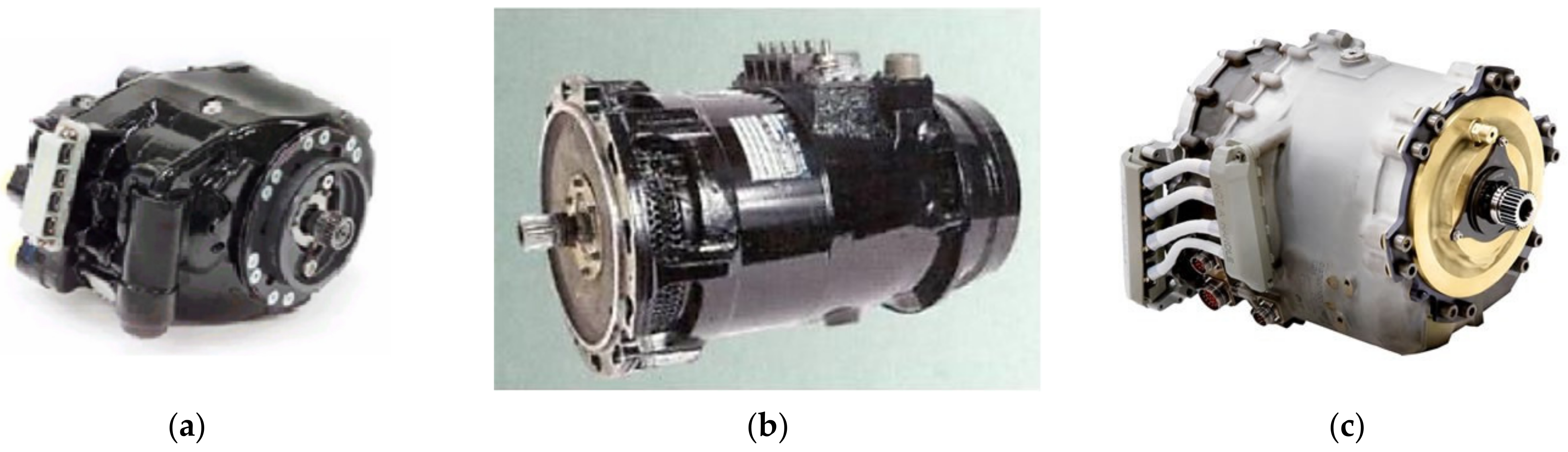
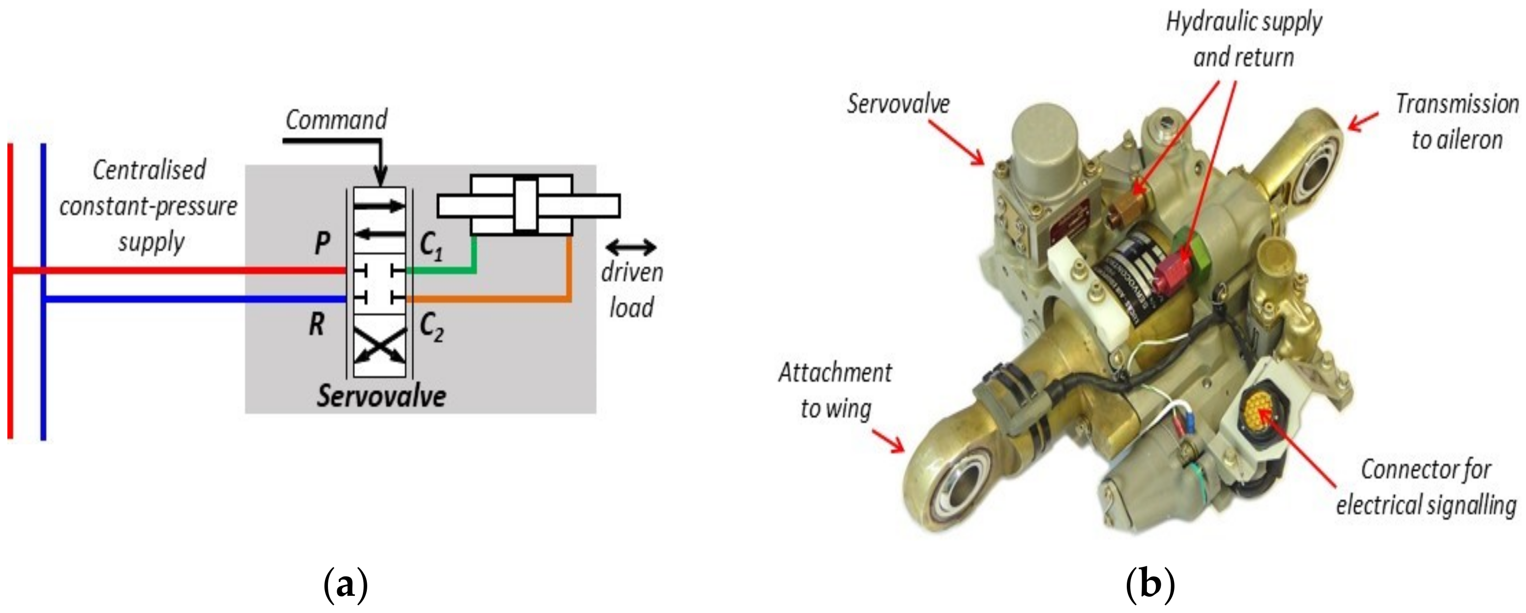
2]. Since the 1950s, they have become the preferred solution for high force/low speed, high power density actuation, whatever the type of aircraft: commercial/corporate/military, fixed wing/rotary wing/space launcher. Such so called “conventional actuators” are extensively used today for safety critical applications like flight controls (primary and secondary), landing gears (extension/retraction, steering, braking), engines (inlet guide vanes, air intake, thrust reverses), and utilities (e.g., cargo doors or ramps). Brought into service in 1959, the Sud Aviation Caravelle, was one of the first commercial aircraft to use non-reversible, hydraulically supplied actuators for primary flight controls (
Figure 1a). At this time, the actuators were mechanically signaled by the pilot or the autopilot. The Airbus A310 initiated the era of fly-by-wire, where electrical signaling has progressively replaced mechanical signaling. In the latest programs, e.g., Airbus A350 (
Figure 1b), hydraulically supplied actuators for flight controls are now digitally signaled and implement the position control loop locally, enabling fly-by-less-wire signaling architectures.
2. Drawbacks of Power-by-Pipe
In conventional actuation, a pressurized liquid is used to convey energy in hydrostatic form between the hydraulic pump and the users. Hydraulic power is generated at a central location, the aircraft engines, and distributed to every actuator at a constant pressure. Each actuator involves components in charge of controlling power, managing power and, ultimately, transforming hydro-mechanical power to drive the actuated load.
The recent progress in power electronics, electric motors, and control strategies have opened up promising horizons for electrically supplied actuation. The following drawbacks of the conventional technology are generally cited when the intention is to abandon it in favor of power-by-wire.
2.1. Global and Local Efficiencies
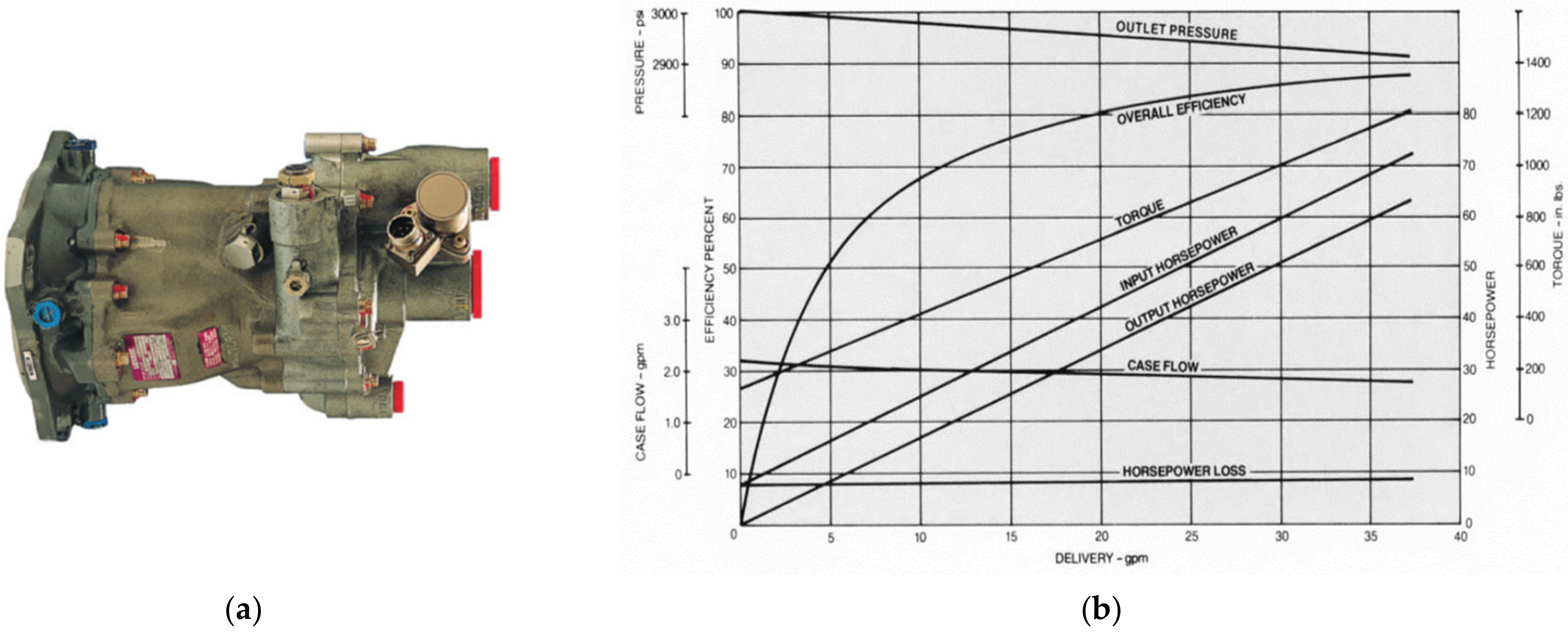
2.1.1. Hydraulic Power Generation
The main hydraulic pumps are permanently driven by the engines. Their design, variable displacement/pressure compensation, enables them to deliver a quasi-constant pressure whatever the flow demand. It requires a permanent external leakage flow at the pump case drain to collect the internal leakages coming from hydraulic bearings and dynamic sealing between moving parts, and to avoid excessive heating at very low fluid delivery. Precisely, these pumps operate at a low percentage of their rated flow most of the time. This has a direct effect on the pump volumetric efficiency, which drops rapidly at partial delivery. To illustrate this, a twin-engine, single-aisle aircraft is considered. The overall internal leakage of its main hydraulic system is typically 10% of the pump rated flow. At this delivery, the pump case drain flow represents about 6% of the pump rated flow and the pump overall efficiency is lower than 40% (
Figure 2).
2.1.2. Control of Power
In the conventional design, power is controlled by throttling: a metering valve, generally a servovalve, controls variable hydraulic resistances between the supply lines and the cylinder or hydraulic motor chambers (
Figure 3). Consequently, all supply pressure in excess of the load pressure is wasted as a pressure loss at the variable orifices of the metering valve. Whatever the force to be produced at load, the actuator draws the same power at source as for the maximum stall force it could generate (power for max force). The efficiency of the control of power is proportional to the load pressure and is only 66% at the rated power transferred from the valve to the cylinder. The mean efficiency of this control of power is low because the actuators operate mainly at very partial load in normal conditions [
3]. This is particularly true for the flight control surfaces, e.g., the rudder, that are not aerodynamically loaded during a great part of the flight.
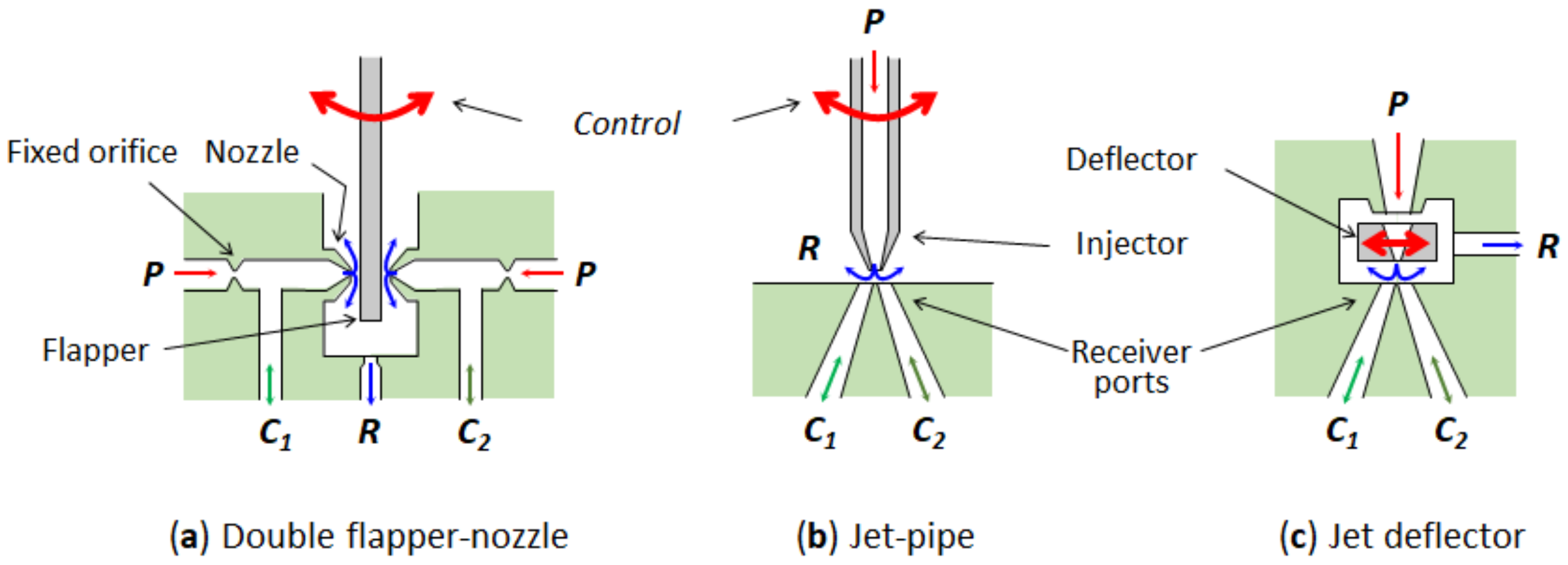
2.1.3. Internal Leakage
Common servovalves involve a hydromechanical pilot stage to increase their power density and typically limit the electrical command power to 100 milliwatts. All pilot stages (jet pipe, deviator, or flapper-nozzle) operate on the flow divider principle [
4] (
Figure 4), which generates a permanent flow consumption. As shown in [
3], this leakage flow is the most penalizing effect in conventional actuators when their efficiency over a typical mission is compared to that of EHAs or EMAs. The pilot stage leakage flow adds to that of the main control valve, which is maximum at null opening and almost proportional to the servovalve rated flow. For quantitative illustration, these leakages are assumed to be 0.25 l/mn for each servovalve operating at 210 bar (3000 psi). Therefore, the overall flow consumption due to servovalve leakage for an aircraft involving 30 flight control electrohydraulic servoactuators, reaches 15 L/min, which makes a permanent power loss of 5.25 kW. Additionally, the presence of hydraulic pilot stages does not allow correct operation of the main control valve to be tested prior to flight without energizing the actuator.
2.2. Management of Power Networks
In redundant hydraulic systems supplying safety-critical actuation functions, the need to make the power networks independent puts tough constraints on power management or reconfiguration. In order to avoid any propagation of external leakage or fluid pollution between networks, crosslinks are generally not welcome, except in particular cases for emergencies. This directly affects the operation of commercial aircraft (in particular, the ETOPS level [
5] and the vulnerability of military aircraft).
2.3. Environment Friendliness and Risk of Fire
Since the 1960s, the chemical industry has developed fire-resistant hydraulic fluids for commercial aircraft, in response to fire accidents that were mainly initiated at the brake level, where there is a huge source of heat close to hydraulic equipment. Their self-ignition temperature must now be greater than 399 °C [
6]. Unfortunately, these phosphate-ester fluids turn partially into acid in the presence of a small amount of water. They irritate skin, are suspected of causing cancer and are harmful for aquatic life, with long lasting effects. Other aircraft (military, helicopters, launchers) use semi-synthetic, mineral-base hydraulic fluids that are more flammable but less aggressive. However, all hydraulic fluids used in aerospace have a high toxicity and therefore a very low environment friendliness.
2.4. Nonlinear Behaviour
The behavior of hydraulically-supplied, valve-controlled actuators is structurally non-linear. The metering valve gain depends on the pressure difference at its use ports, and on the fluid temperature. Its dynamics decays with the command magnitude and the supply pressure. The reflected load inertia has a great effect because it combines with the hydromechanical stiffness of the actuator fluid domains to produce a poorly damped dynamics, which alters the closed-loop performance of position control. This hydromechanical stiffness depends on the load position and is generally minimal at the centered position [
7]. Primary flight controls and landing gear steering are precisely position-controlled and operate averagely in the centered position. Due to the combination of all these effects, non-specialists often find the actuator control difficult to design.
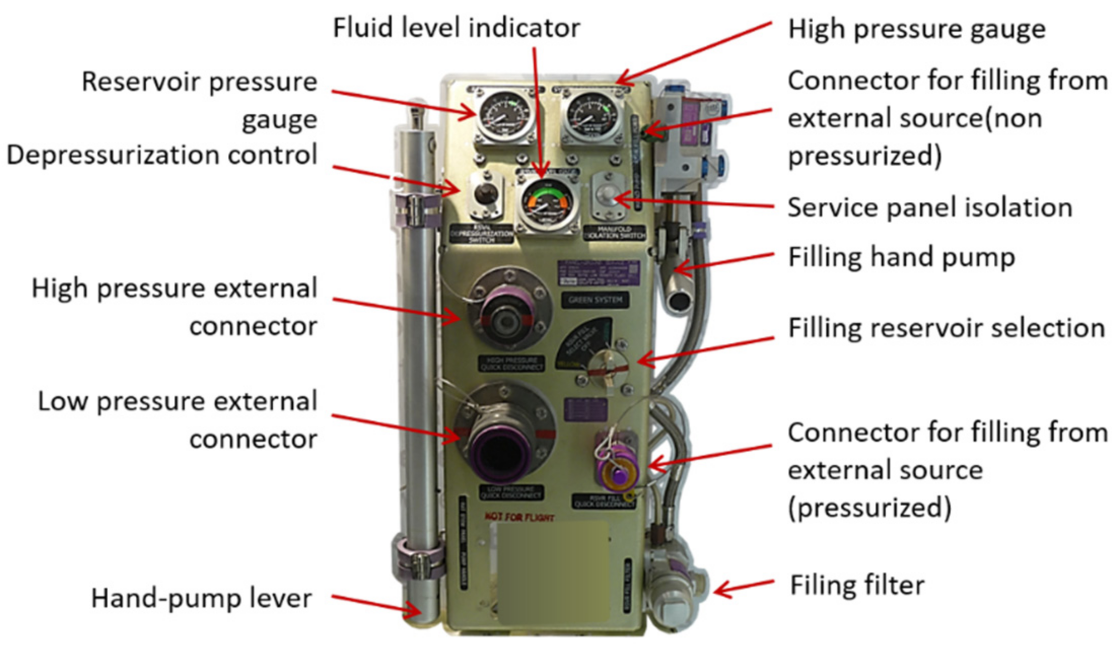
2.5. Integration and Maintenance
The hydraulic fluid must typically perform its energy carrying function for several 10 thousands of hours. Therefore, it must be present in sufficient quantity, and sufficiently free of solid/gaseous/foreign liquid pollution. Solid pollution is really a concern, especially for servovalves, which require clearances of a few micrometers between their moving parts to meet the performance requirements. The hydraulic fluid must also be kept within a defined temperature range so as not to become degraded and not to reduce the mechanical and volumetric efficiencies too much at low and high temperatures, respectively. During aircraft assembly, as well as for maintenance, fluid conditioning requires special skills, rigorous, safe practices, and dedicated on-board hydraulic equipment (see
Figure 5) for bleeding, filtering, periodic checks, monitoring and reservoir filling. It is also worth mentioning that the fluid toxicity imposes a hard constraint on designers for the routing of the hydraulic networks, e.g., because no hydraulic circuit is generally allowed in a pressurized area of a commercial aircraft. This is to avoid spraying in case of leakage.
To close this section, it is important to note that most of these drawbacks come from the use of a material (the hydraulic fluid) to convey energy between sources and users.
3. Advantages of Electrically Supplied and Hydraulic-Less Actuators
In the last two decades, advances in power electronics, electric motors, and associated control strategies have opened up promising horizons for electrically supplied actuation. The huge increase in maturity and reliability is making it more and more attractive for safety-critical aerospace applications [
8].
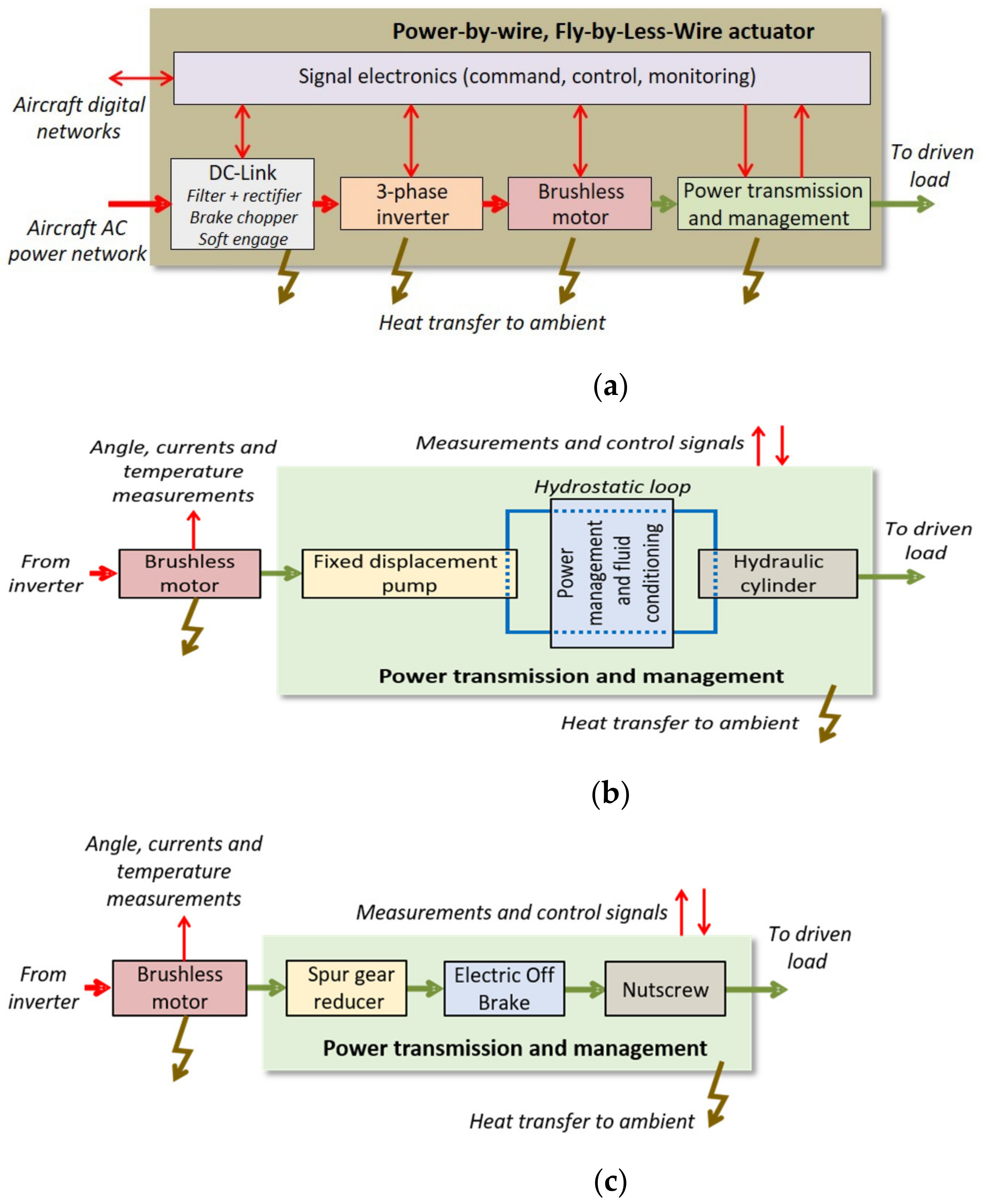
As shown in
Figure 6a, an electric drive supplied from an AC electric network typically involves a DC-link, a brake chopper, an inverter, a brushless motor and the motor control electronics. In around 2005, Airbus introduced electro-hydrostatic actuators (EHAs) into the A380,
Figure 6b. These combine the advantages of both technologies: PbW on the power network side, and hydraulics on the load side. This concept is now in service in various types of aircraft: commercial, corporate and military. In this design, the electric motor drives a fixed displacement pump at variable speed and the pump is connected to the hydraulic cylinder to make a hydrostatic loop. Total removal of the hydraulic fluid is achieved in electro-mechanical actuators (EMAs,
Figure 6c). EMAs are now in service for secondary flight controls and even for low power LGER [
9]. In such hydraulic-less designs, the motor drives the load through a mechanical reducer. Linear EMAs are the most common. They use a power screw for its compactness and high reduction ratio.
As addressed synthetically below, PbW actuation has numerous potential advantages, in particular where hydraulics shows drawbacks.
3.1. Weight
It is well known that hydraulic equipment items like pumps or actuators offer an unbeatable power density. Unfortunately, this advantage vanishes when the whole hydraulic system is considered (in large aircraft, rudder actuators may be as far as 40 m from the main pump). For a double-deck aircraft, the weight of the supply and return pipes, fittings and brackets can be twice that of the hydraulic equipment itself. The weight of the hydraulic fluid is also to be considered: more than 200 kg for Airbus 320 family, more than 600 kg for the Boeing B-747 [
10]. For the same power carrying capability, electric power networks are much lighter than hydraulic power networks.
3.2. Control of Power
The power transferred between the DC-link and the motor is controlled at the inverter level though fast on/off switching of power transistors. Unlike valve control in hydraulics, the control of power does not introduce any functional loss (power-on-demand). The inverter operates as a variable-ratio power transformer with extremely low parasitic losses: its efficiency is typically greater than 95%.
3.3. Electromechanical Power Transformation
The last two decades have seen impressive developments in electric motors and their control, producing amazing steps in efficiency and power density. This mainly comes from the combination of rare earth permanent magnets, the electronic commutation of the motor windings, advanced field oriented control (FOC) strategies, and freedom in electromagnetic design: type of winding, magnet mountings, and tooth shape, e.g., [
11].
3.4. Control
Control engineers like electric drives for various reasons. The behavior of electric motors is globally linear. In addition to the position loop, the motor control involves current and speed loops, naturally implementing a cascade control architecture. The dynamics generally differs greatly from one loop to another, which facilitates a step-by-step setting from the inner current loop to the outer position loop. There are also numerous degrees of freedom that can be used to optimize the operation of the motor by action on the magnetic field orientation (e.g., maximum torque for current or flux weakening) [
12]. Last but not least, the presence of a high ratio reducer between motor and load significantly reduces the influence of the driven load on the control performance, generally.
3.5. Environment Friendliness
Electrons do not pollute and do not leak.
3.6. Health-Monitoring
The control of PbW actuators requires current, speed and position sensors. They can be combined with additional sensors, e.g., temperature of motor and power electronics, to monitor the actuator health status. The presence of electronic signal boards, with their processors and memories, enables health-monitoring functions to be run locally, including pre-flight checks. The significant scientific knowledge and practical experience acquired in health monitoring of industrial electric drives benefits the implementation of diagnostic and even prognostic features for aerospace actuation, e.g., [
13,
14,
15]. The increasing market of drones or unmanned aerial vehicles (UAVs) opens new opportunities to design and implement health-monitoring features at actuators level. In [
16], self-monitoring concepts are proposed for simplex EMAs driving the flight controls surfaces of a medium-altitude long-endurance (MALE) drone. Multirotor UAVs are also considered, e.g., with focus on fault tolerant actuators involving dual redundant motors [
17], or robust fault detection and isolation [
18].
3.7. Integration and Maintenance
Conveying energy without conveying any material facilitates integration and maintenance. As there is no need to worry about fluid pollution, bleeding or purging, PbW components or equipment can be mounted/dismounted using a pure plug and play approach. For example, the replacement of an electric brake actuator (EBA) on the landing gears of the Boeing B-787 requires only two bolts and one electric connector to be disassembled,
Figure 7. Another consideration is of high importance concerning maintenance, in particular for military operations or for aircraft operated in a remote location far from maintenance centers: skills in electro-technology are always available because they are already needed to support the other systems of an aircraft.
3.8. Management of Power Networks
The risk of propagating faults between channels of a redundant electric power distribution system is extremely low. If necessary, a redundant electric power distribution system can be reconfigured by interconnecting or isolating power networks with bus ties. This offers multiple options to supply the safety critical actuators with dissimilar power sources, to increase their availability, and finally to fly and land safely even in the presence of multiple faults.
3.9. Power Generation
Recent aircraft programs have introduced step changes in power generation and distribution [
19]. Variable frequency generators (VFG) or starter generators VFSG (typically 350 to 800 Hz) have been brought into service to replace the heavy and complex integrated drive 400 Hz generators (IDGs,
Figure 8). There are four VFG of 150 kVA each on the Airbus A380 and four VFSG of 250 kVA each on the Boeing B-787. On the Boeing B787 and Airbus A350, the voltage of the AC networks has also been doubled from 115 VAC to 230 VAC, giving high voltage DC sources (HVDC) of ± 270 V after rectification. In the latest programs, these advances significantly increase power density and reduce maintenance. PbW actuation can also take advantage of power networks supplying functions that are not priority or that are not active at the same time in the flight mission. This possibility of mutualization of the electric power generation and distribution channels also provides an efficient means to reduce weight.
4. A More Realistic View
In practice, things are not so simple. Drawbacks never come without advantages and vice-versa. Although it is very common practice to focus our minds on the disadvantages of the current solution and on the merits of the new solution, it is necessary to make an effort to keep a global, realistic vision.
4.1. Mitigation of Drawbacks of Conventional Actuation
Firstly the solutions used to limit some drawbacks mentioned in
Section 2 for conventional actuation deserve a mention.
4.1.1. Overcenter Control
For rotary actuators, valve control can be replaced by overcenter control of a variable displacement motor. As the motor operates as a variable power transformer, power is drawn “on demand” and the control of power does not generate any energy loss, functionally speaking. This significantly reduces the flow demand and helps to downsize the hydraulic system. This alternative has been introduced on the Airbus A380 for high lift systems (flaps and slats) [
20,
21].
4.1.2. Direct Drive Valves (DDV)
DDV do not involve any pilot stage. This removes the first stage leakage but the servovalve command input requires more power to drive the main control valve directly. This solution has been applied to some flight controls or landing gear actuators for military aircraft (Saab Grippen, Eurofighter Typhoon, Rockwell B1-B, and Dassault Rafale) and helicopters (NH industries NH90) [
22,
23].
4.1.3. Leakage and Fire
During more than 60 years of experience, leakage and fire hazards have been significantly reduced by rigorous application and continuous updating of standards, recommended practices, lessons learned for quality, integration and maintenance practices.
4.1.4. Weight
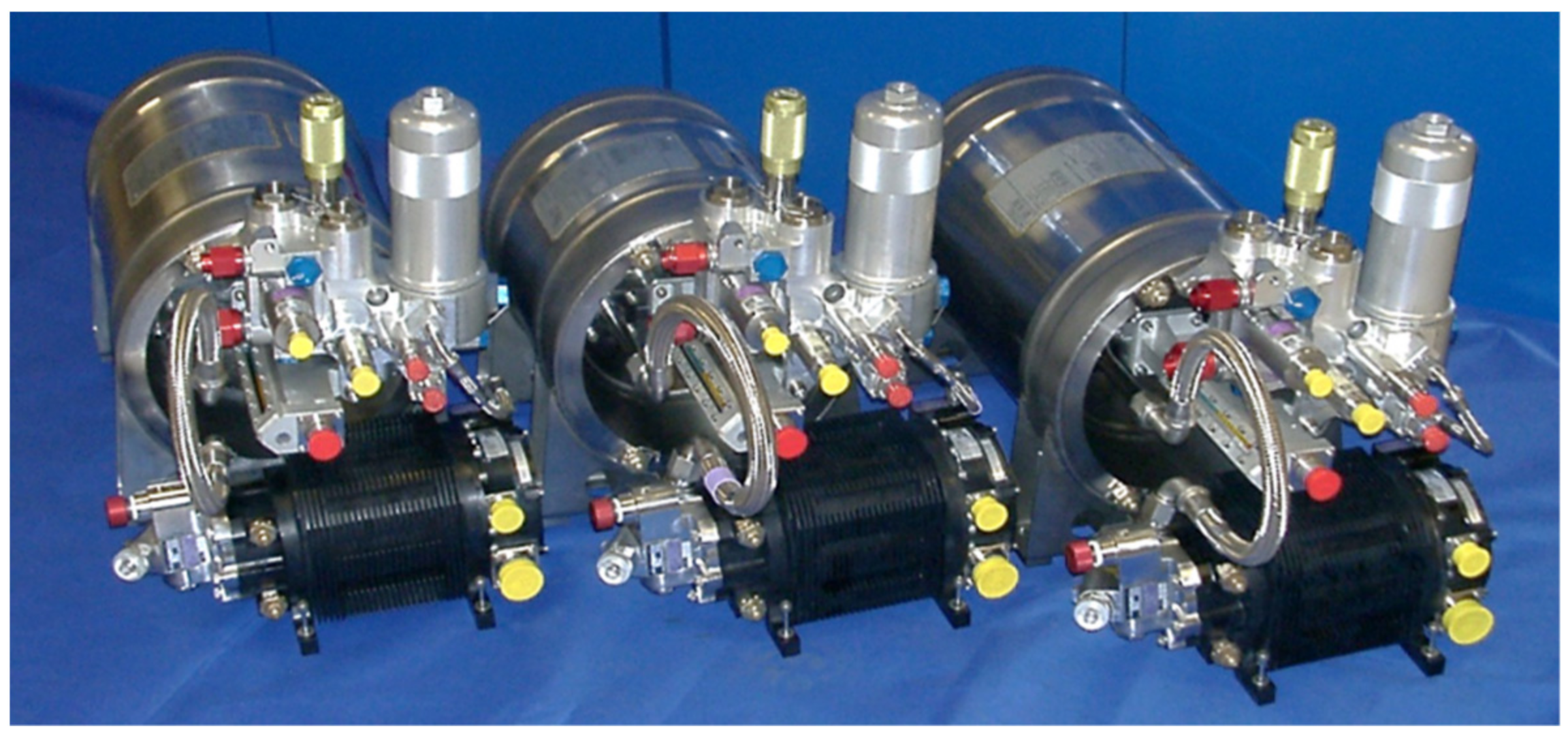
Two main solutions can help to mitigate the weight penalty coming from the power distribution piping. On the one hand, increasing the supply pressure of the hydraulic system produces a weight saving that comes mainly from the reduction of the overall volume of hydraulic fluid and the diameter of the return lines. On the other hand, local power generation (recently named zonal hydraulics) from a nearby electrical power network can avoid the use of long pipes, especially for actuators that are active for very short periods of time and located far from the engine driven pumps. Both concepts have been introduced on the Airbus A380 [
24]. The supply pressure has been increased by 66% (from 210 to 350 bars), saving 20% of the hydraulic system weight. Three local electro-hydraulic generation systems (LEHGS) have been used for the backup supply of landing gear steering and braking (
Figure 9).
4.1.5. Control
The control design of electrohydraulic actuators is now extensively documented, e.g., [
25]. The numerous candidate options for anticipating the effect of nonlinearities and poorly damped hydromechanical mode, either at electric or at hydraulic level, are well mastered today. This being said, the potential disadvantages of PbW actuation can be identified and analysed.
4.2. Need for Mechanical Reducer
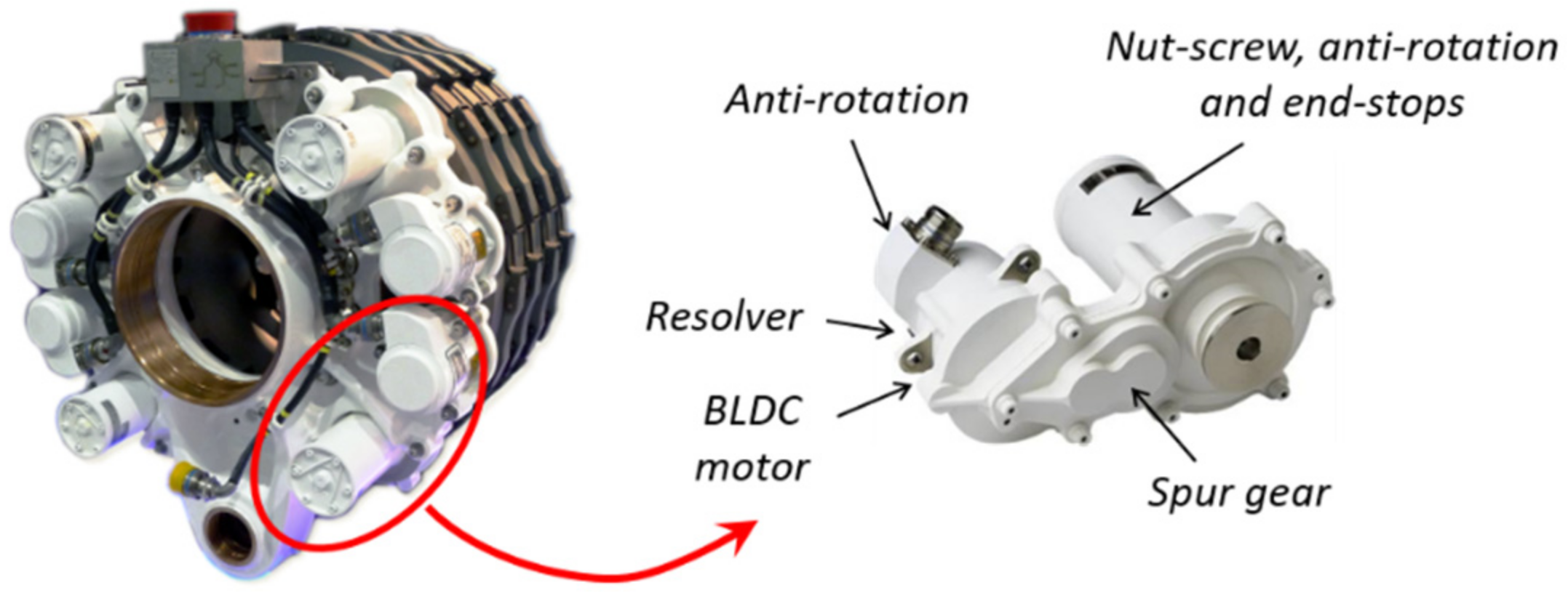
The majority of actuators use brushless synchronous electric motors because they offer the best torque density. The airgap torque developed by such motors comes directly from the product of current in the windings, active length of wires, and magnetic field. Unfortunately, all these contributors involve heavy materials: copper for windings, magnets and laminates for generating and conveying the magnetic field. Finally, the weight of the motor is determined at first order by the torque it is required to produce (an order of magnitude is 1 kg/Nm). For the aerospace actuators considered, the torque to be developed on the moving loads is high. For a single-aisle twin-engine aircraft like the Airbus A320, up to 200 Nm are required to drive the ailerons, while its nose landing gear steering actuator must be able to develop more than 7000 Nm on the turning tube. Gimballing the nozzles of the boosters of the Ariane V launcher requires more than 350+ kNm. For a given power need, it is therefore advantageous, in terms of weight, to use high-speed motors (typically from 1500 to 15,000 rpm). This is why PbW actuators need a power transformation: hydrostatic loop for EHAs, gears or nutscrews for EMAs, as shown in
Figure 6 and
Figure 10.
4.3. Thermal Balance
Several important considerations concern the thermal balance of PbW actuators:
4.3.1. Heat Exchange
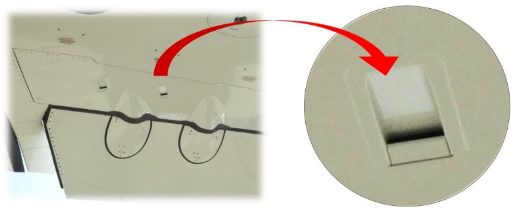
In conventional actuators, the hydraulic fluid is also a good heat conveyor to evacuate the heat generated by throttling and other energy losses to the reservoir through the return hydraulic lines. This intrinsic advantage does not exist in PbW actuators because, unfortunately, electrons do not carry heat. The heat generated by all actuator energy losses must thus be stored or exchanged to ambient at the actuator level. This difference is even amplified when the actuator must hold a permanent force at null speed, e.g., for ailerons or elevators in cruise flight phase. In conventional actuators, holding a permanent pressure difference in a cylinder does not spend any energy, except that one coming from the servovalve and manifold internal leakages. On the contrary, holding a permanent motor torque in an EMA generates permanent copper losses in the motor windings, and conduction and switching losses in the power electronics. This explains why it is often necessary to force heat convection at PbW actuators that are continuously active and loaded. An example is given in
Figure 11 with the scoops installed for cooling the A350 aileron EHAs by means of outside dynamic air. This is not for free: a scoop generates drag and weight, with a cumulative effect on wing and engine sizes.
4.3.2. Motor Sizing
The non-conductive insulation materials used to coat the electric wires of motor windings progressively degrade when their temperature increases. Thus, the lifetime of a motor is directly linked to the time history of the operating temperature of its windings. This makes the winding temperatures a major driver for motor sizing. Winding temperature is a direct consequence of conduction (or copper) losses, which are, in turn, proportional to the electrical resistance of conductors multiplied by the square of the current in wires. As winding current is proportional to the airgap torque developed by the motor, the sizing of the motor from the thermal point of view depends greatly on the effective mission time history. The root mean square (RMS) torque is commonly computed for the mission history data to provide the designers with a simplified requirement that is representative of the thermal loading of the motor [
27]. For a given aircraft, defining the right actuator mission to be used for thermal sizing is a challenging task, given the variety of operators, flight durations and profiles, approach types, and aircraft use (not forgetting training and testing). According to the author’s 20-year experience in more electric actuation projects, this difficulty is emphasized by the lack of available sizing mission data. This is because the design of conventional actuators did not require any mission profile, as it has a negligible impact on their design.
4.3.3. Thermal Divergence
Another effect also makes the designers’ work trickier. When the temperature increases, the magnetic induction of permanent magnets decreases (e.g., −4% for 100 °C in SmCo magnets), thus reducing the motor torque constant. Consequently, more current is needed to produce the same airgap torque. On top of that, the resistance of electric wires increases with temperature (+40% for 100 °C for copper) and the conduction and switching losses in the power transistors also increase (up to 20% for 100 °C). When the temperature increases, the current produces more energy loss and a rise of the temperature of the motor and power electronics. However, this is not a fully diverging thermal loop because the thermal exchange to ambient at the motor surface and power electronics heat sink improves. For example, the natural convection heat flow between a horizontal plate and free air at −20 °C is multiplied by 8 when the surface temperature increases from −10 °C to 90 °C).
4.4. Imperfect Mechanical Transmission
For EMAs, a mechanical reduction function is still needed between the motor shaft and the driven load, to make the actuator sufficiently light. As in linear conventional actuators, driving the load through a three or four-bar mechanism already produces a mechanical power transformation through the effective lever arm of this operating mechanism. In practice, EMAs (even rotary or linear) include another reduction function. Unfortunately, this power transformation is not ideal. Several imperfections are impossible to avoid in its technical realization.
4.4.1. Friction
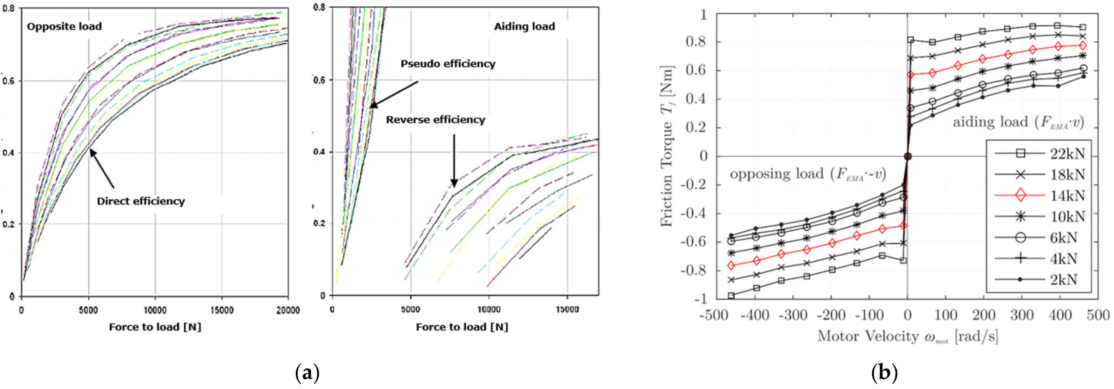
Friction between bodies moving relative to each other can be drastically reduced by replacing sliding with rolling, as is done in ball or roller power screws, for example. However, friction does not occur only in power transmission devices like gears or screws. It has also to be considered at seals and joints. This is particularly true for linear EMAs, which involve power screws: additional friction comes from the seals, the antirotation function of the translating rod, and the axial thrust bearing for the rotating element of the nutscrew. Finally, internal friction is not negligible for EMAs. It makes their overall mechanical efficiency lower than expected a priori, as illustrated in
Figure 12.
For actuator sizing and energy considerations, care must be taken not to use only the efficiency at rated output force, because it drops rapidly at partial load, at low speed and at low temperature. As shown in
Figure 12a left, the maximum direct efficiency tends to 80–90% at full load, but it drops to 40–60% at 20% load. The backdriving efficiency is also important, e.g., in towing mode for the steering actuation of nose landing gears, or for active/standby redundant actuation where the passive actuator is driven by the active one. In
Figure 12a right, the actuator becomes irreversible for a backdriving load corresponding to 8% of the rated load. The backdriving efficiency does not exceed 40% at 20% aiding load.
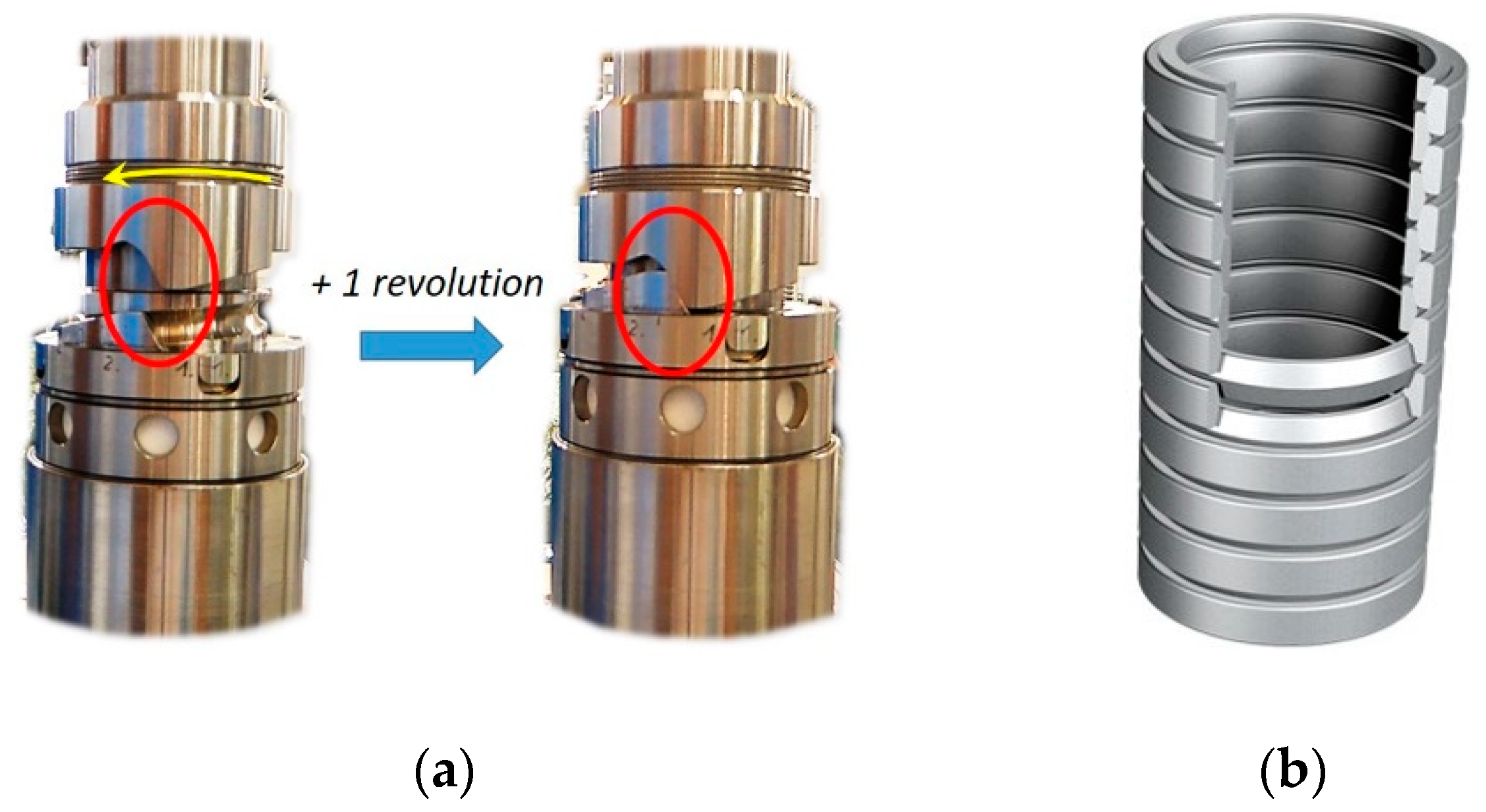
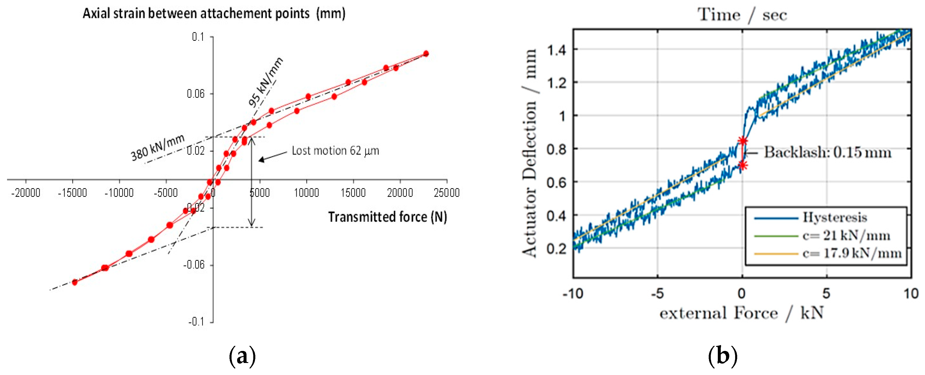
4.4.2. Compliance and Backlash
Solids transmitting or reacting with loads in EMAs are not infinitely rigid: they behave like very stiff springs. Power transmission functions are also affected by backlash or by lost motion when backlash is avoided by resorting to preloading (at the expense of additional friction). These effects are quantified by plotting the mechanical axial compliance of the EMA, as illustrated in
Figure 13.
The backlash present in the compliance plot in
Figure 13a is observed in
Figure 13b due to the 10% preloading. Backlash is thus replaced by a reduced stiffness in the +/−0.02 mm lost motion domain. EMAs are, however, much stiffer than conventional actuators: a conventional actuator having the same stroke and rated force would be several times more compliant than an EMA.
4.4.3. Weight and Reflected Inertia
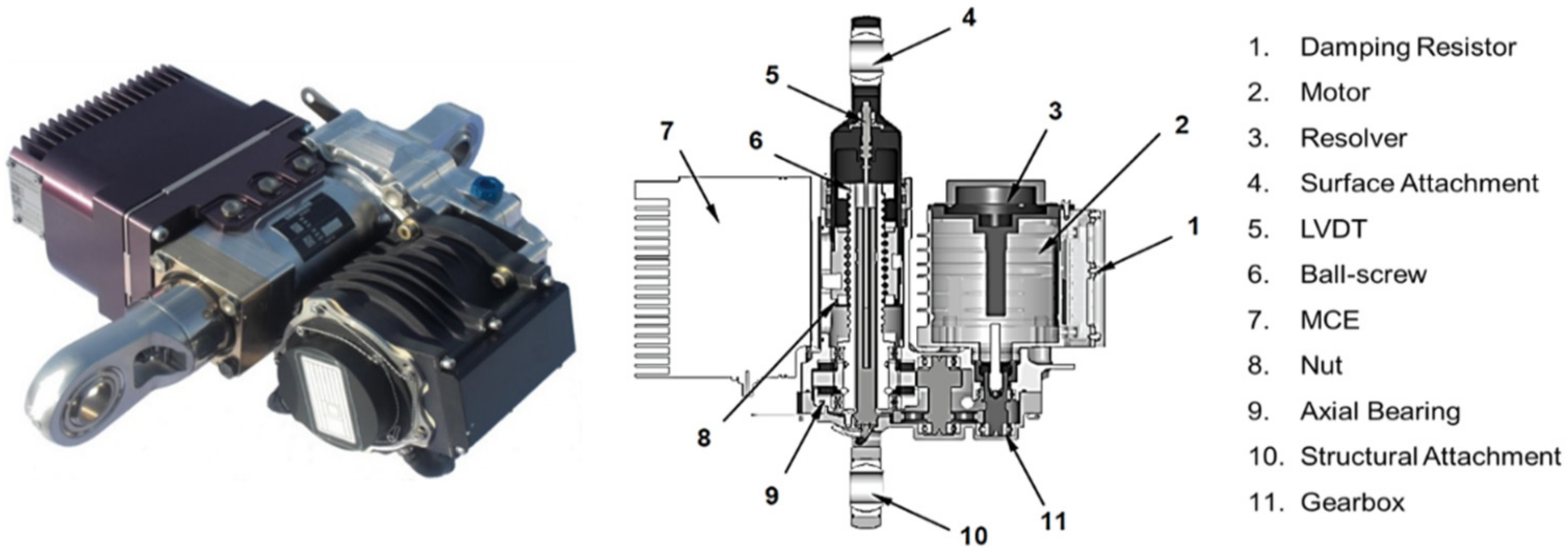
In the presence of a mechanical reducer, the inertance effect of the motor shaft reflects at the load level with the multiplicative factor being the squared value of the reduction ratio. From a dynamic point of view, this is equivalent to attaching tremendous inertia to the driven load. For illustration, an Airbus A320 aileron EMA would reflect an inertia effect at the aileron level that can reach 10 to 40 times the aileron moment of inertia on its hinge axis. This effect is absent in conventional actuators: for the same example, the reflected inertia coming from the cylinder rod mass is only a few thousandths of the aileron moment of inertia. The EMA reflected inertia at load level is very penalizing from a dynamic point of view. It has to be addressed with attention to sizing. Firstly, the kinetic energy stored by the motor rotor can generate huge dynamic loads during shock on stops. This generally requires special devices to absorb the kinetic energy without damaging the rolling contacts (
Figure 14).
Secondly, for dynamic applications like thrust vector control (TVC), most of the airgap torque serves to accelerate the motor rotor itself. As the rotor inertia is directly linked to the motor torque capability, this adds a second sizing loop to the thermal one for the power sizing of the motor [
27]. Thirdly, it makes the dynamic load rejection weak: e.g., in the presence of a gust on the control surface, the reflected inertia opposes rapid motion and thus may generate excessive transient structural loads. However, adding a force feedback in the position control [
30] is an efficient way to remove this latest drawback.
4.4.4. Risk of Jamming
Power transmission through contacts with mechanical obstacles, like gear teeth or nutscrew threads and high-speed bearings, may cause jamming in cases of insufficient lubrication, rupture, alteration of facing solids under shocks, or in the presence of foreign debris. Yet, jamming is not tolerated for numerous safety-critical applications: primary flight controls, landing gear steering and extension/retraction, when it causes an active failure at aircraft level. In these cases, the actuation function has to be made jamming-tolerant or jamming-resistant by design [
31], putting a high penalty on complexity, weight and volume. As the risk of jamming of hydraulic cylinders is negligible, jamming in EMAs is undoubtedly a major factor discouraging the replacement of conventional actuators by EMAs for such uses.
4.4.5. Need for Lubrication
In EMAs, there is also a need for lubrication of the mechanical power transmission elements and bearings. Lubrication reduces friction and wear and cools the loaded contacts between moving parts. It is a major concern for the design of maintenance-free EMAs for aircraft being operated as long as 25 years, for 100,000 flight hours. In contrast, conventional actuators benefit from the lubrication properties of the hydraulic fluid. This is another side advantage of fluid power.
4.4.6. Power Management
Depending on the load needs and selected actuation architecture, several power management functions must be performed within the actuator: breaking, declutching, torque limitation, torque/speed summing, damping, or soft endstop. In the conventional technology, friction and inertia effects are sufficiently low to make the cylinder pressure difference a good indicator of the rod force (in other terms, there is little loss between the hydrostatic force and the force to load). This enables the power management functions to be implemented in a compact and light manner by using dedicated valves (for isolation, bypass, pressure relief, throttling, or snubbing). In EMAs, the mechanical reducer, electric motor and inverter all behave, ideally, as power transformers. Therefore current should be an accurate representative of the EMA output force. As the winding currents and rotor speed are already measured for controlling the motor, it is tempting to implement the above-mentioned power management functions digitally, as code lines in the software that drives the inverter. Unfortunately, the transfer between EMA output force and motor current is altered in practice by the friction and compliance of the mechanical reducer and in dynamic conditions by the inertia of the motor rotor. Moreover, such an implementation cannot perform these functions in cases of failure of the electric supply, software, electronic boards, or motor. The designers are thus constrained to implement these functions in the mechanical domain of the EMA, downstream of the motor shaft, and as closely as possible to the load interface–another effect that makes EMAs bulky and heavy.
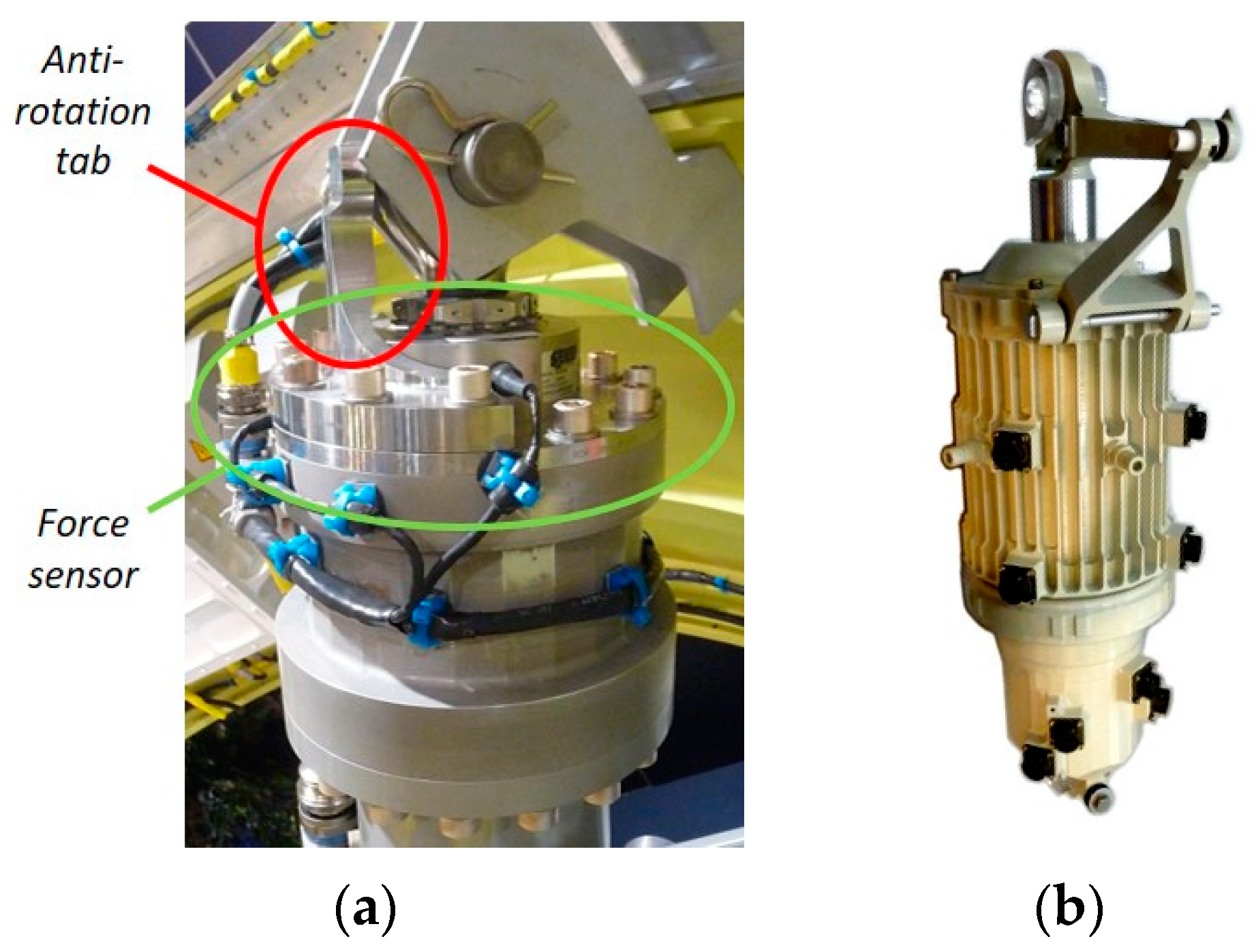
4.4.7. Reaction Forces
For mechanical integration, conventional linear actuators made of hydraulic cylinders appear as a motorized cylindrical joint. The translational motion is the functional one. The rotational degree of freedom gives internal mobility to the actuation kinematics. It is, however, limited e.g., with resort to side pads on the spherical bearings that are used to anchor the actuator body to the airframe (
Figure 15a) and to attach the actuator rod to the driven load. Finally, in the common 3-bar kinematics, the airframe and the driven load are only loaded, from a functional point of view, by the axial actuation force. Linear EMAs may generate additional reaction forces. There is a need to avoid the rotation of the translating element of the nutscrew. Without special provision in the EMA, the corresponding reaction torques must be produced by the airframe and the load themselves. This generates additional structural loads to be considered during design. However, the global tendency is to remove this new crosslink between structure and actuator design. This is achieved in practice by implementing the anti-rotation function within the EMA, e.g., with a linear spline, compass, or even a non-circular rod (
Figure 15b).
4.5. Control
Several considerations concerning control implementation distinguish PbW for conventional actuation:
4.5.1. Endstop to Endstop Motion
The first one is related to applications in which the driven load has simply to be moved between two endstops, typically LGER or engine thrust reverse. In conventional actuation, there is no need for closed loop control: the actuator is commanded in an on/off manner (extension/retraction for landing gears, deploy/stow for thrust reversers). The load speed is set by fixed hydraulic resistances between the directional valve and the cylinder while the deceleration prior to reaching the endstop is achieved through snubbing. In contrast, PbW actuation requires at least control loops for the switching of motor windings, with the associated sensors, electronic hardware and software. Pure speed control is generally sufficient but it requires two additional discrete position sensors to trigger deceleration when approaching the endstops. This has noteworthy impact on complexity and cost. However, some suppliers are currently taking a detailed look at the use of AC motors that would avoid or simplify the electronic part.
4.5.2. Design Assurance Level
Unlike conventional actuators, PbW actuators involve a lot of electronics and software for control. This comes, in particular, from the inner current loops, which are needed to control switching of the motor windings at a high frequency (typically around 10 kHz), according to the rotor/housing relative angular position. For safety-critical applications, their development must meet numerous requirements and recommended practices, e.g., DO-174 [
33], to provide the right level of confidence ensuring safe and secure flights. In this context, the development of electronics and software for PbW actuation generates a huge, expensive workload. However, the best practices have spread rapidly and numerous off-the-shelf software packages make this development more and more straightforward.
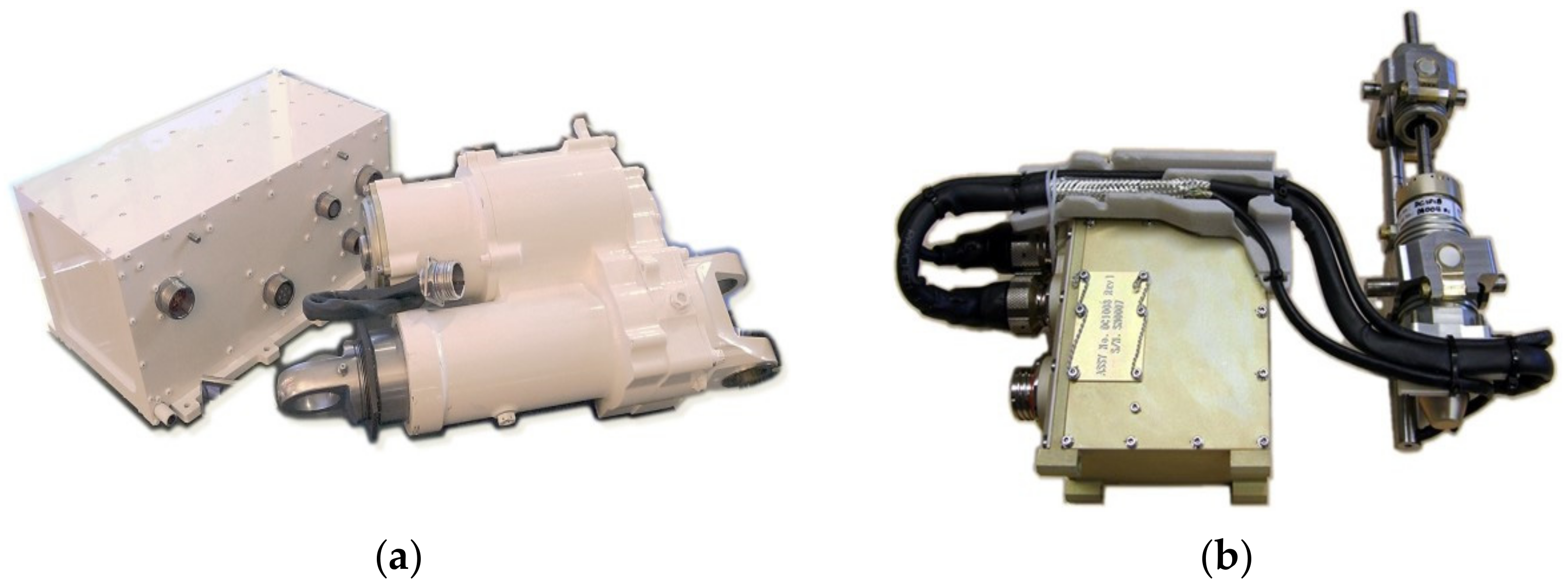
4.5.3. Weight
Besides controlling power, the power and signal electronics of PbW actuators also has to implement rectifiers and filters to ensure immunity to external electromagnetic noise (electromagnetic compatibility, or EMC) and limit the emission of electromagnetic noise (electromagnetic interference, or EMI) as well. The filters are heavy and bulky. They make the electronics of PbW actuators a significant contributor to the overall weight and space envelope, as illustrated in
Figure 16. This is particularly well illustrated by the example of the thrust vector control actuators of the Vega launcher: 42 L/34 kg for the electronics against 156 kg for the 2 actuators of the first stage, and 12 L/9.5 kg of electronics against 7.4 kg for the two actuators of the upper stage.
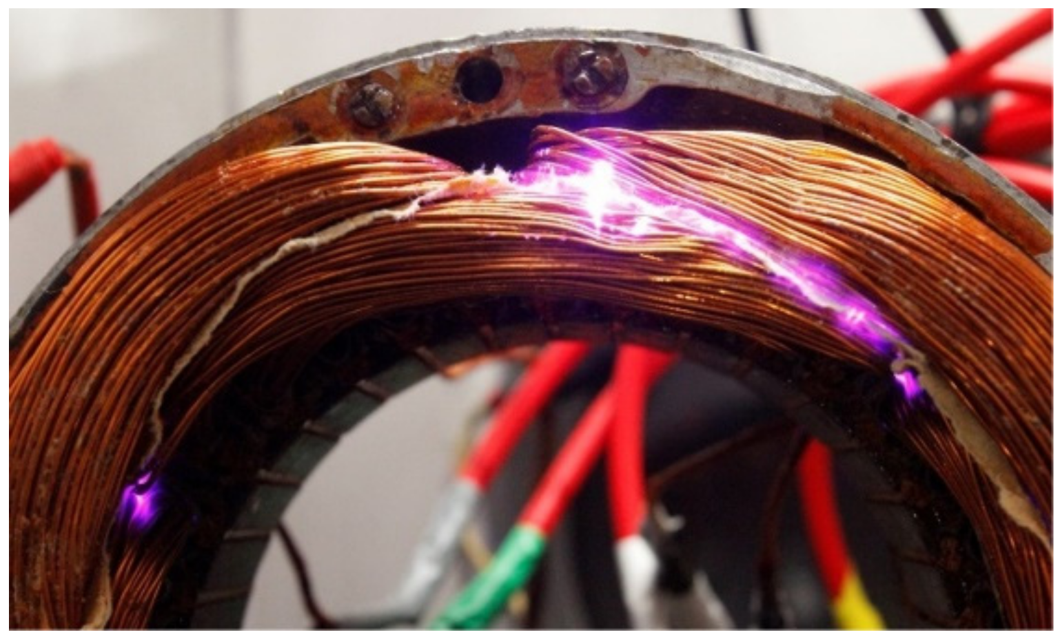
Weight can also be saved by increasing the supply voltage in order to reduce the current in wires and power electronics. However, this option is limited in practice. High frequency switching of low-loss power transistors yields steep-front voltages in the electrical wires (up to 5 kV/s), which generate over voltage [
35]. When the potential increases beyond the partial discharge inception voltage (PDIV), typically 600 V, the magnetic field ionizes the ambient air. If the conductors are too close to one another, ionization leads to partial discharges that degrade the electric insulation. Motor and power electronics are particularly exposed to this so-called corona effect [
36], which increases when pressure drops (at high altitudes) and when the distance between conductors is small (e.g., between coils of the motor windings,
Figure 17).
5. Discussion and Perspectives
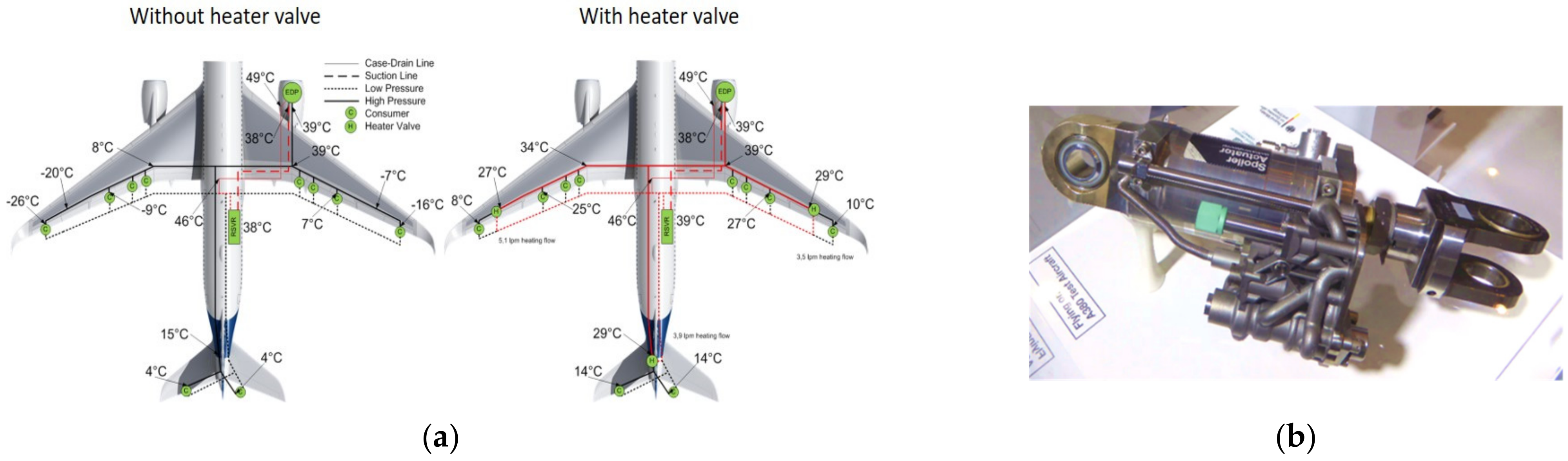
Today, the industry has acquired more than 60 years’ experience in using hydraulically supplied actuators for safety-critical aerospace applications. Since their introduction, the architecture, control and power density of such actuators have been continuously improved. There is still room for progress, as illustrated in
Figure 18: downsizing the hydraulic network by better management of the hydraulic fluid temperature on the Airbus A350 [
37] or reducing the cost and weight of hydraulic components though Additive Layer Manufacturing [
38]. However, it is becoming more and more difficult to identify potential gains and to implement them efficiently on the market.
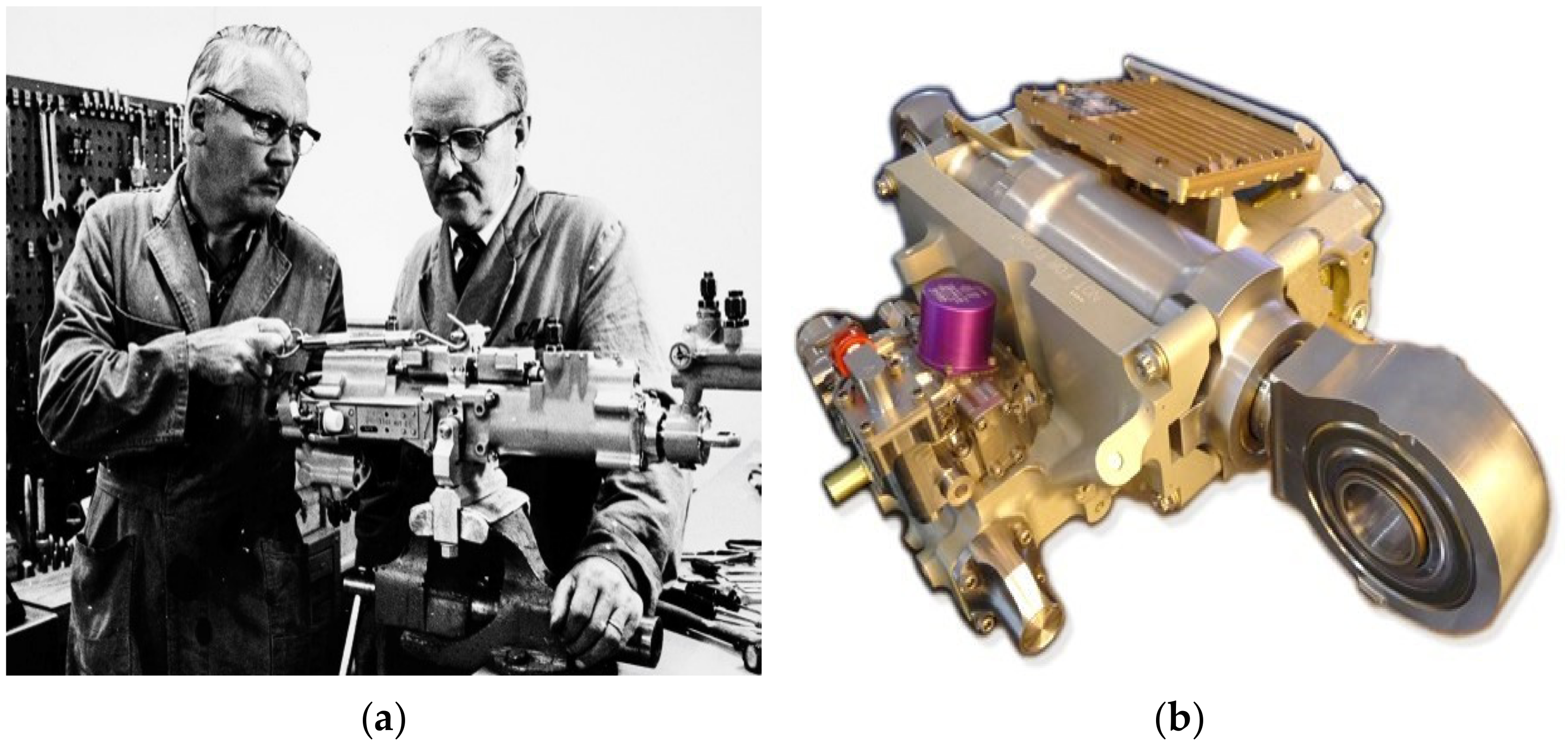
An analysis of the evolution towards PbW has to consider the time scale of the life of an aircraft. Bringing the maturity of a given design from a technology readiness level TRL5 (validation in a relevant environment) to TRL 9 (in service) may take 10 to 20 years, as illustrated by the example of the EHAs. Typically, an aircraft is produced over a period of 30 years and the last one produced is operated for another 30 years. Thus, some aircraft will still be flying in more than 70 years with the technology that is being demonstrated at TRL 5 today. This shows how important it is to progress step by step when a new technology is planned to replace a conventional one. Step changes are rare in aerospace, where preference is given to incremental innovation. The most obvious example is the introduction of Fly-by-Wire for electrical signaling of the actuators. From the Airbus A310 (which introduced digital signaling on a commercial aircraft for the first time) to the Airbus A380, it took 25 years for the full removal of any mechanical signaling for safety-critical actuation systems.
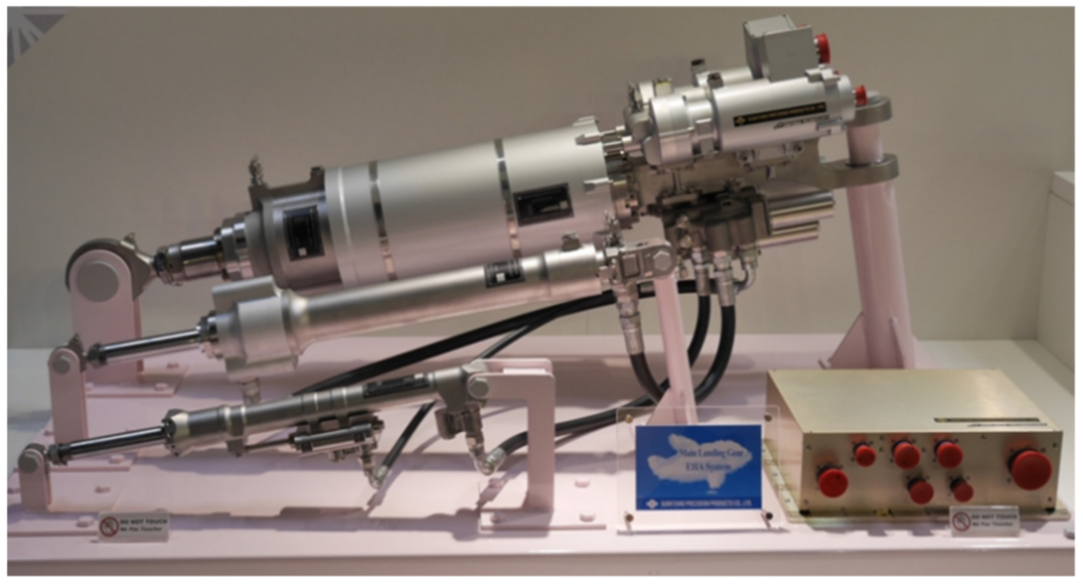
For flight controls, major evolution steps typically occur every 25 years: hydro-mechanical actuation in the 1960 s, FbW in the 1980 s, PbW with EHAs in the 2000 s and PbW with EMAs in the 2020 s. Landing gear actuation is on the way towards hydraulic-less actuation, as illustrated by the recent first EASA certification of LGER EMAs for vertical take-off and landing (VTOL) aircraft,
Figure 19.
PbW actuation offers a fantastic potential for evolution. Its advantages are well identified and the main need now concerns the mitigation of its drawbacks. Much promising research and development is ongoing, at various maturity levels. This deals, of course, with electricity, electronics and electromagnetics: HVDC networks, matrix converters, energy regeneration, SiC or GaN power transistors, new magnetic architectures and superconductors for motors, etc., but is not confined to these areas. The preceding sections have also shown that numerous limitations of PbW stem from physical effects that belong to the scientific domain of mechanics. This is why PbW is also generating huge amounts of activity in tribology (e.g., dry lubrication), heat transfer (e.g., heat pipes or phase change materials (PCMs)) and even in zonal hydraulics (e.g., mutualization of electrically-supplied hydraulic generation for landing gears in the Thermae II project [
39],
Figure 20).
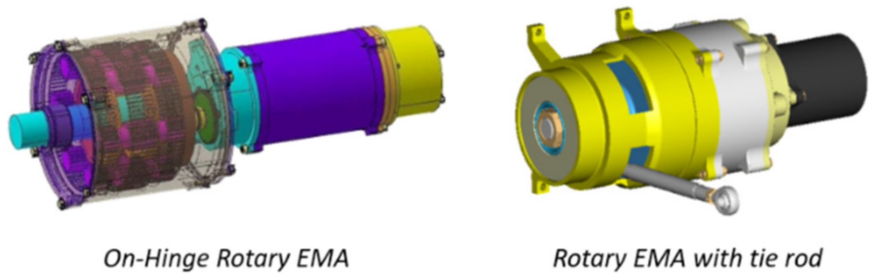
There is also a need to reconsider the integration of the actuators within the airframe. For EMAs, it seems illogical to use an intermediate linear motion to transmit mechanical power from a rotating motor to a rotating load: simply replacing conventional actuators by PbW ones is not the ultimate best option. There is thus a need to re-consider the actuator/airframe/driven load integration. There are many options, which still need to be maturated: new concepts for distributed actuation [
40] or wing morphing [
41], new actuation architectures to transmit (or react to) the actuation loads e.g., using on-hinge or tie-rod Geared Rotary Actuators (GRAs),
Figure 21.
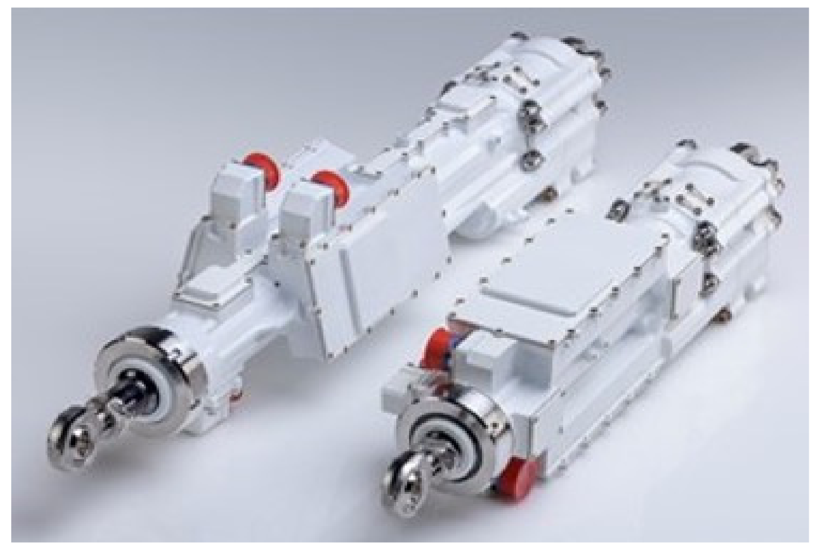
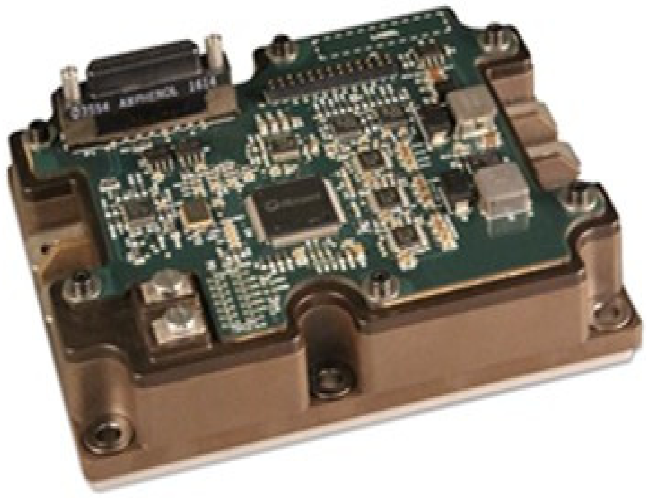
Additionally, two design concepts can undoubtedly help to reduce cost, weight and development time. The first one is mutualization. As already mentioned, many actuators do not operate at the same time. Moreover, some of them operate in sequence: e.g., up-unlock/gear-down/down-lock before landing, then braking after touch down. This makes it possible to mutualize the power networks and the actuator electronics (including heat sinks and DC-link), in a way similar to that investigated in the Thermae II project. Additionally, the non-essential electric loads can be disconnected so that safety-critical ones can be supplied in case of reduced power capability on a given supply network. This enables the power distribution system to be downsized while still meeting the reliability requirements. The second concept is modularization and standardization, [
43,
44]. Development costs are high in aerospace, in particular for qualification and certification. Decomposing an actuator into modules that are standardized can potentially reduce cost- and time-to market. This is well illustrated by
Figure 22, which displays a cost-effective module combining a 5 kW hybrid power drive and a power core module controller [
45]. However, for power transmission devices, modularization and standardization come with a weight penalty that makes the solution more difficult to implement in practice for geometrical interfaces of mechanical elements (e.g., reducers and nut screws) than for signal or power electronics (e.g., power control modules (PCMs), and control and monitoring modules (CMMs)).
6. Conclusions
Today, three key target qualities: greener, safer and cheaper, drive aerospace designs. In this logic, PbW actuation is not a target in itself but simply a very promising means to meet these broader aims. At a given date, the choice of a technology must be driven by performance, not solution, according to its current (or expected) maturity. In fact, a complete system view must drive the decision-making process, because the targets must be considered at the level of the final stakeholders: the passenger, the aircraft maker, the operator and, last but not least, the planet. This makes it decisions hard, because it requires sharing knowledge between aircraft makers and system suppliers, none of whom can individually assess the global gains versus the technology steps. Besides the intrinsic advantages of PbW and the drawbacks of power-by-pipe, it is important to not to forget the intrinsic drawbacks of the former and the intrinsic advantages of the latter:
PbW actuators call for much greater torque density of electric motors and power density of power electronics, in combination with lower energy losses and advanced means to store/evacuate heat. To date, the unavoidable need for a mechanical reducer increases the actuator reflected inertia. It does not allow all power management functions to be performed in the electric domain and it is prone to jamming, which is not accepted for many safety-critical applications.
Hydraulically supplied actuators are mature, and their integration within the airframe is well established. The hydraulic fluid, used to convey energy, is also used to evacuate the heat generated by the actuator energy losses and to ensure lubrication. Hydraulic cylinders allow direct connection to the driven load with a very small reflected inertia. Most of the power management functions at actuator level can be implemented in the hydraulic domain at low mass and volume.
Keeping this in mind, designers have first developed and brought to market some intermediate hybrid solutions, which take the best of each technology: EHAs and zonal hydraulics.
The tremendous margin for progress of power by wire, and the huge research activity deployed every day, favor their use for safety-critical actuation in the very close future. PbW is now well established for two main types of applications: firstly, transient actuation or short missions like thrust vector control of launchers or secondary flight controls, where the heat generated by energy losses can be stored thanks to the thermal capacitance of the EMA solids; and secondly, when a locked load is the preferred response to an actuation failure (including jamming), as for flap and slat actuators. The present increasing demand for drones and flying taxis boosts development of electric propulsion for aircraft. Additionally, the massive and increasing production rates in the electric car industry is continuously cutting the cost of electric drives. In this context, PbW is becoming more attractive every day for safety-critical actuation in aerospace.


