Communication

A Thickness-Mode High-Frequency Underwater Acoustic Transducer with a Low Sidelobe Level

1
College of Underwater Acoustic Engineering, Harbin Engineering University, Harbin 150001, China
2
Underwater Acoustic Transducer Lab, Shanghai Marine Electronic Equipment Research Institute, Shanghai 201108, China
3
School of Materials Science and Engineering, Shanghai University, Shanghai 200444, China
*
Authors to whom correspondence should be addressed.
Actuators 2021, 10(9), 226; https://doi.org/10.3390/act10090226
Submission received: 26 August 2021 / Accepted: 4 September 2021 / Published: 8 September 2021
(This article belongs to the Special Issue Advances in Piezoelectric Actuators 2022)

Abstract

:
Thickness vibration mode is commonly used for high-frequency transducers. For disc piezoelectric ceramics, there is no ideally pure thickness vibration mode because the coupling between the radial and thickness modes always exists. Furthermore, it also deteriorates the transmission voltage response and directivity of the high-frequency transducer. In this paper, based on the theoretical calculation and finite element simulation method, a new method was proposed, and the related experiment was carried out to convince this idea. Both the simulation analysis and experimental results show that drilling a hole at the center of piezoelectric vibration is a simple but effective method to obtain a pure thickness vibration mode of the disc piezoelectric ceramic, and then improve the transmitting ability and directivity of the high-frequency piezoelectric transducer. The sidelobe level is as low as −21.3 dB.

1. Introduction

High-frequency transducers are widely used in underwater acoustic systems [1]. Because the working frequency of the high-frequency transducer is high, it can obtain sharp directivity, which is helpful for sonar systems to identify the type and shape of underwater fine targets. In recent years, many new materials have been used in the field of underwater acoustic high-frequency transducers, but piezoelectric ceramics are still the mainstream materials. Piezoelectric transducers with piezoelectric ceramic as the functional material have higher reliability, impact resistance and long-time working stability than flexible sensors. It is the mainstream device of underwater acoustic systems [2,3,4,5]. The thickness vibration mode is the dominant working mode for high-frequency transducers. Because the resonance frequency of the thickness vibration mode is relatively high, the coupling effect is common in high-frequency transducers. For disc piezoelectric ceramics, it is difficult to obtain an ideal thickness vibration mode. Changing piezoelectric sample sizes can weaken the coupling effect. However, the sample size was usually fixed. On the one hand, the coupling reverses the vibration displacement of the piezoelectric vibrator surface, leading to decrease of the transmission efficiency of the transducer. On the other hand, the coupling causes multiple indistinguishable resonance peaks to appear near the thickness vibration frequency. Furthermore, coupling makes the resonance frequency, impedance characteristics and other important parameters of the transducer less consistent. It makes the transducer difficult to design to obtain high yield.
Many transducer experts have had extensive discussions on high-frequency broadband transducers [6,7]. One-dimensional vibration theory was often used to approximate the thickness vibration of ideal piezoelectric discs, while radial coupling must be considered for finite-size piezoelectric discs [8]. As early as 1977, Mori et al. proposed the apparent elasticity method to deal with the coupling vibration of piezoelectric vibrators [9]. Lin Shuyu, et al. introduced the equivalent elastic coefficient into the coupled vibration of piezoelectric disc plates and rings by an analytical method, and derived the equivalent circuit and resonance frequency equation of multimode coupled vibration of piezoelectric ceramic vibrators [10,11], Li Mingxuan et al. also analyzed the stress voltage characteristics of the high-frequency thickness mode transducer, and gave the characteristics of high-frequency oscillation under different loads [12].
Besides the theoretical calculation studies, the finite element simulation method was also employed to investigate the coupling effect. Guo N., Kocbach J. and Lee P. used the finite element method and numerical analysis method to analyze the coupled vibration modes of piezoelectric oscillators, and calculated the second-order theory of transversely coupled longitudinal vibration piezoelectric crystals [13,14,15]. D. Kybartas et al. used the finite element method to analyze the electromechanical coupling coefficient of each order vibration mode when the transverse and longitudinal ratio of the piezoelectric vibrator is different, and the influence of different piezoelectric materials on the electromechanical coupling coefficient of the coupling mode [16]. Hu Jing et al. studied the cylinder vibration system with strong radial and axial coupling. When the appropriate geometric size was selected, the vibration system could effectively radiate high-power ultrasound [17]. Lee h, et al. studied the near-field and far-field acoustic radiation characteristics of the radial vibration of a piezoelectric ceramic disk, and calculated the analytical solution of the modal acoustic radiation of a thick disk with a free boundary [18,19,20]. However, up to now, most of the coupling analysis seeks to understand the coupling characteristics of piezoelectric vibrators and there have been few studies on how to reduce the coupling effect.
In this paper, the resonant frequencies of the radial and thickness vibration of the oscillator were calculated, and the influence of the coupling effect was analyzed by solving the frequency equation of the multimode coupling vibration of the finite size piezoelectric disc oscillator. In order to optimize the thickness vibration mode and a low sidelobe level, a new method of drilling holes at the center of the piezoelectric disc vibrator is proposed. The radial higher-order vibration frequency was adjusted by using the size of the center aperture, so that the thickness vibration mode was pure. The experimental results showed that the relatively pure thickness vibration mode was achievable by using the piezoelectric ceramic disc with a central hole, which provided an effective method for the design of high-frequency transducer.

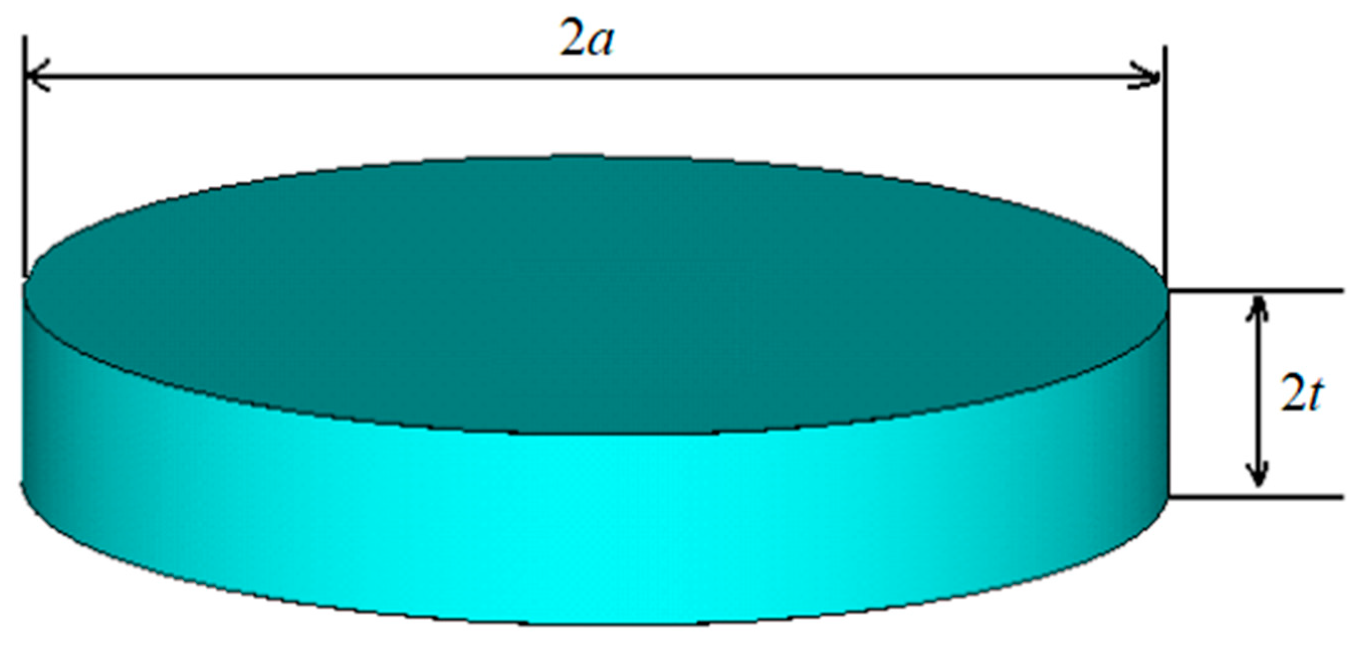
2. Thickness Vibration Mode

2.1. Theoretical Calculation of Vibration Frequency

Considering the coupling vibration, the resonant frequency is closely related to the size of the disk oscillator, and the fundamental frequency of the thickness vibration is quite different from the one-dimensional vibration theory. Figure 1 shows a piezoelectric ceramic wafer polarized along the thickness direction with a diameter of 2a and a thickness of 2t.
According to reference [3], it is deduced that n = T z T r = T θ T r , n is called the coupling coefficient between the radial and thickness of the disk oscillator. The equations of coupling coefficient, radial vibration frequency and thickness vibration frequency are:
s 13 E s 11 E ( s 12 E s 11 E 1 ) n 2 + [ ( s 12 E s 11 E ) 2 + s 13 E s 11 E 4 X 2 ( j ) ( 2 i 1 ) 2 π 2 ( t a ) 2 1 ] + 2 s 13 E s 11 E 4 X 2 ( j ) ( 2 i 1 ) 2 π 2 ( t a ) 2 = 0
f r = X ( j ) 2 π a 1 ρ s 11 E [ 1 ( s 12 E s 11 E ) 2 + s 13 E s 12 E ( 1 s 12 E s 11 E ) n ]
f t = 2 i 1 4 t 1 ρ s 33 E [ 1 + 2 s 13 E n s 33 E ]
where s 11 E ,     s 12 E ,   s 13 E ,   s 33 E are the compliance constant of piezoelectric ceramics. The values of i and j are 1, 2, 3…, and correspond to the higher-order frequency of thickness vibration and the higher-order frequency of radial vibration respectively. X ( j ) = k r a   is the root of equation k r a J 0 ( k r a ) = ( 1 + s 12 E s 11 E ) J 1 ( k r a ) . J 0 ( k r a ) and J 1 ( k r a ) are the zero order and first order of the Bessel function of the first kind. The coupling coefficient n is solved from Equation (1), and then the higher order frequency of radial and thick vibration can be obtained by substituting Equations (2) and (3). From the calculation formula, considering the coupling, the radial vibration frequency is not only related to the material parameters, diameter size, but also the ratio of thickness to diameter, and the thickness vibration frequency is the same. Therefore, the material type, size and structure shape should be further considered.
Taking a PZT-4 piezoelectric ceramic disc with diameter 2a = 60 mm and thickness 2t = 10 mm as an example, the resonant modes of radial vibration and thickness vibration are calculated by (2) and (3). The theoretical calculation and finite element calculation results of piezoelectric vibrator of the same size and material are as follows.
As given in Table 1, the resonance frequency of the radial low-order mode agrees well with the simulation results, whereas the theoretical calculation results of the second and third order of the radial high-order mode are quite different from the simulation results. In addition, there is no corresponding relationship between the resonance frequency and the theoretical value.
The fundamental frequency of the thickness vibration is simulated and calculated, as shown in Figure 2. The fundamental frequency of thickness vibration is clearly affected by the higher-order vibration mode of radial vibration. The vibration amplitude at the surface is distributed symmetrically with the center of the circle as the axis. The vibration amplitude is uneven and wavy. The vibration amplitude near the center of the circle is large, and the vibration amplitude along the radial direction becomes wavy.
When analyzing the thickness vibration mode, the classical one-dimensional theoretical calculation model requires that the transverse dimension is much larger than the longitudinal dimension. Although the theoretical calculation model adopted in this paper does not have this requirement, it also ignores the thickness shear vibration mode, bending vibration mode, etc., and only considers the coupling of the radial mode. What accounts for this? The lower order radial mode calculated is in good agreement with the finite element results, while the higher order mode is not in good agreement with the finite element results. Therefore, the following chapters will use the finite element method to calculate the parameters of the transducer, in order to make the results of the calculation and analysis instructive.
Taking the piezoelectric wafer as an example, when the thickness size is less than the radial size, the piezoelectric disc is in the shape of a slender rod and has pure longitudinal vibration; when the thickness size of the piezoelectric disc is much larger than the radial size, the thickness vibration mode is the main mode near the thickness vibration frequency, and the radial and other coupling modes also exist, but the influence on the thickness vibration mode is less, which is mainly manifested when the two dimensions are comparable, such as 2a/2t = 1~10. The thickness vibration mode is strongly affected by the coupling.

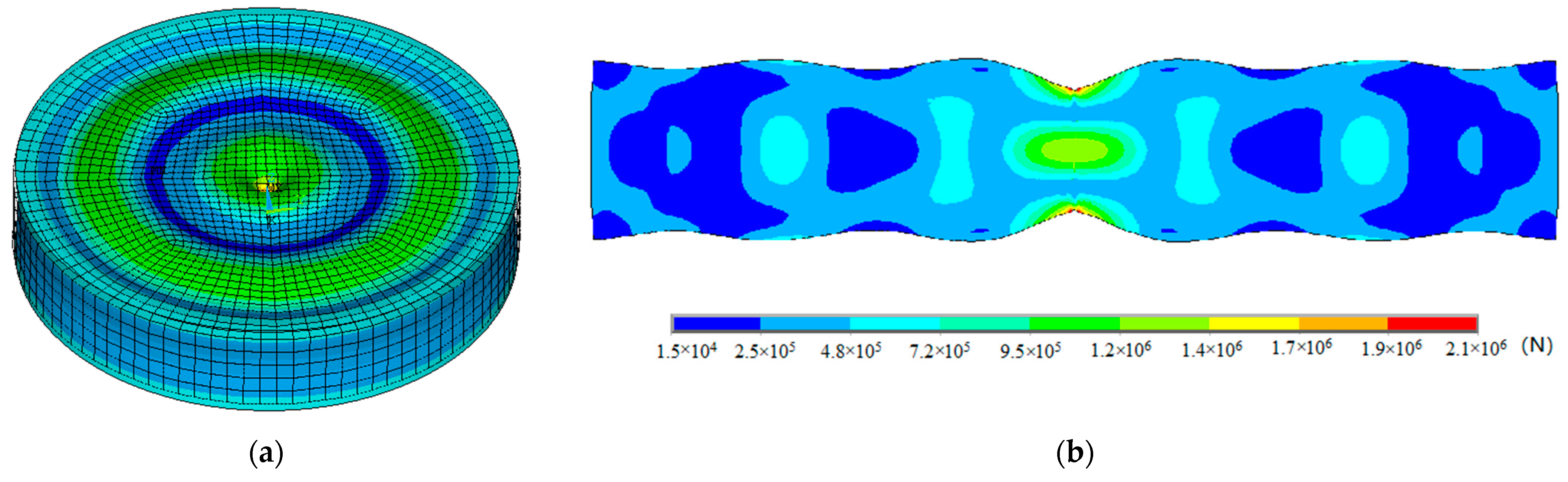
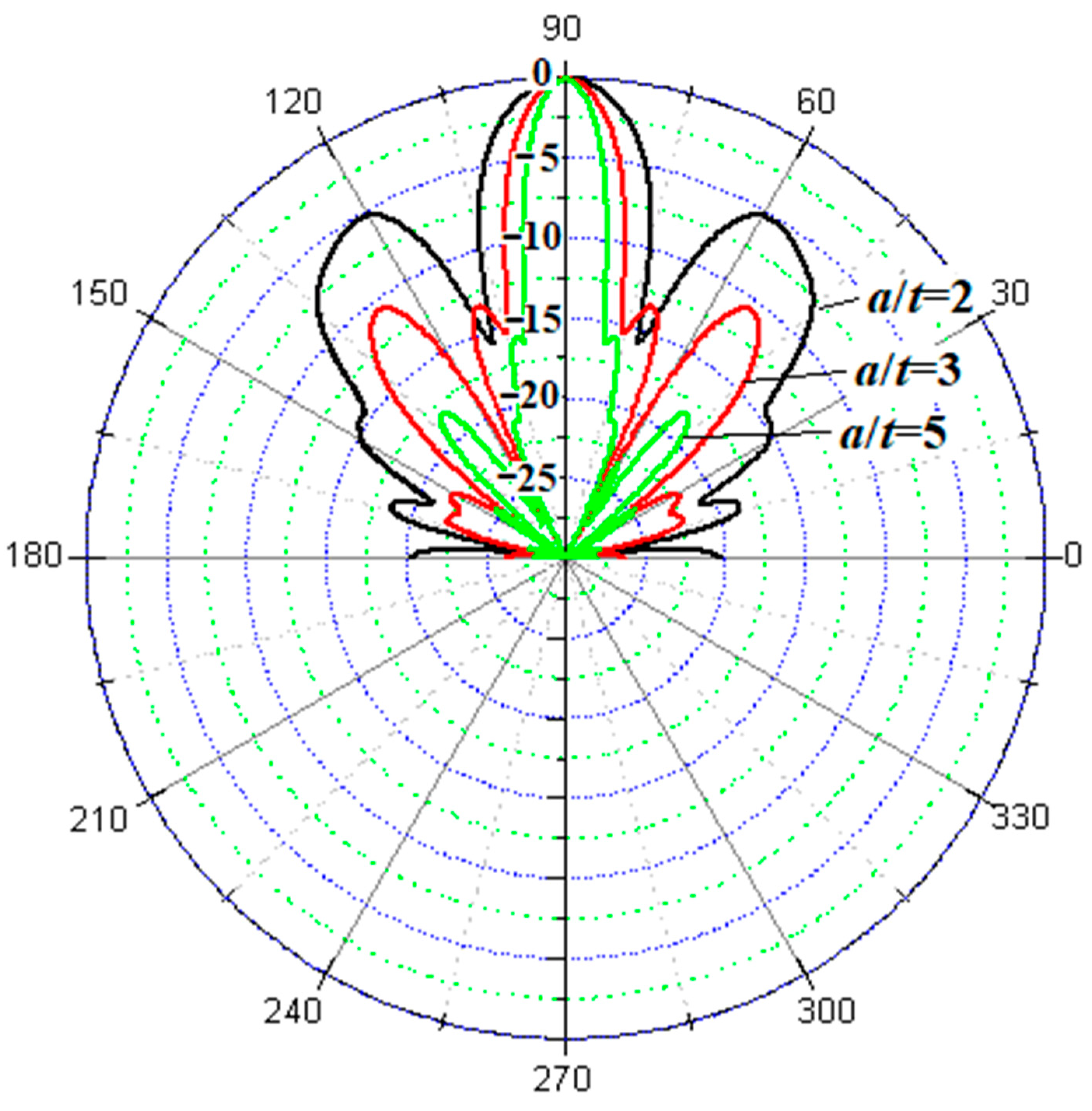
2.2. Sidelobe Level of Conventional Piezoelectric Ceramic Disc Transducer

Due to the limitation of working frequency and directivity open angle, the diameter thickness ratio of the piezoelectric disc is usually between 1 and 10. Figure 3 shows that the sidelobe level decreases with the increase of a/t. In order to obtain the vibration transducer with sidelobe level lower than −10.5 dB, the diameter thickness ratio of piezoelectric disc is required to be a/t > 3. In this range, if the diameter thickness ratio a/t is appropriate, the coupling will be weak, and there is no coupling vibration resonance peak in the vicinity of 10% of the thickness vibration frequency. When a/t is small, it has a great influence on the directional sidelobe level of the transducer.
Figure 3 shows that the sidelobe level of the circular transducer is different with different a/t. When a/t = 2, the sidelobe level of the transducer is −5 dB. When a/t = 3, the sidelobe level of the circular transducer is −10.5 dB. With the increase of a/t, the sidelobe level gradually decreases. Therefore, for the conventional piezoelectric ceramic disc transducer, if the s/t size ratio is not appropriate, the sidelobe level of the transducer will be higher due to the mixed vibration modes.

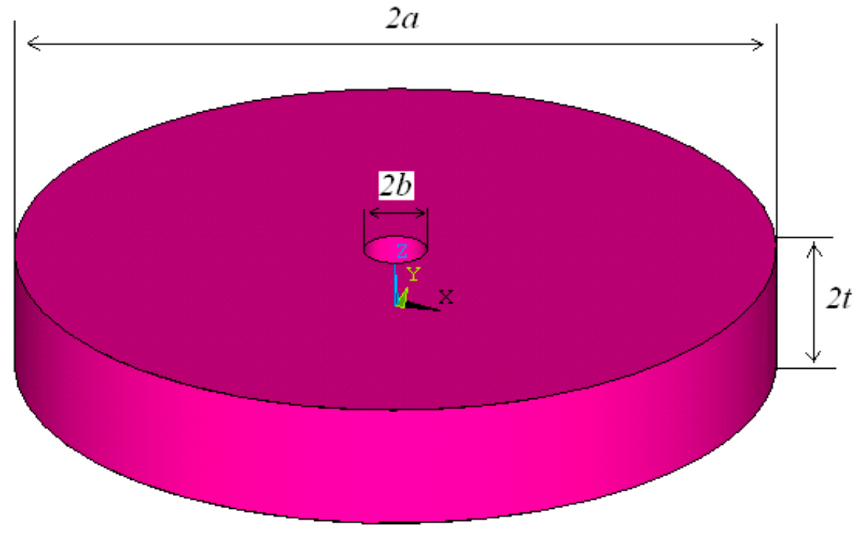
3. Vibration Mode Optimization of Thickness Transducer with a Center Hole

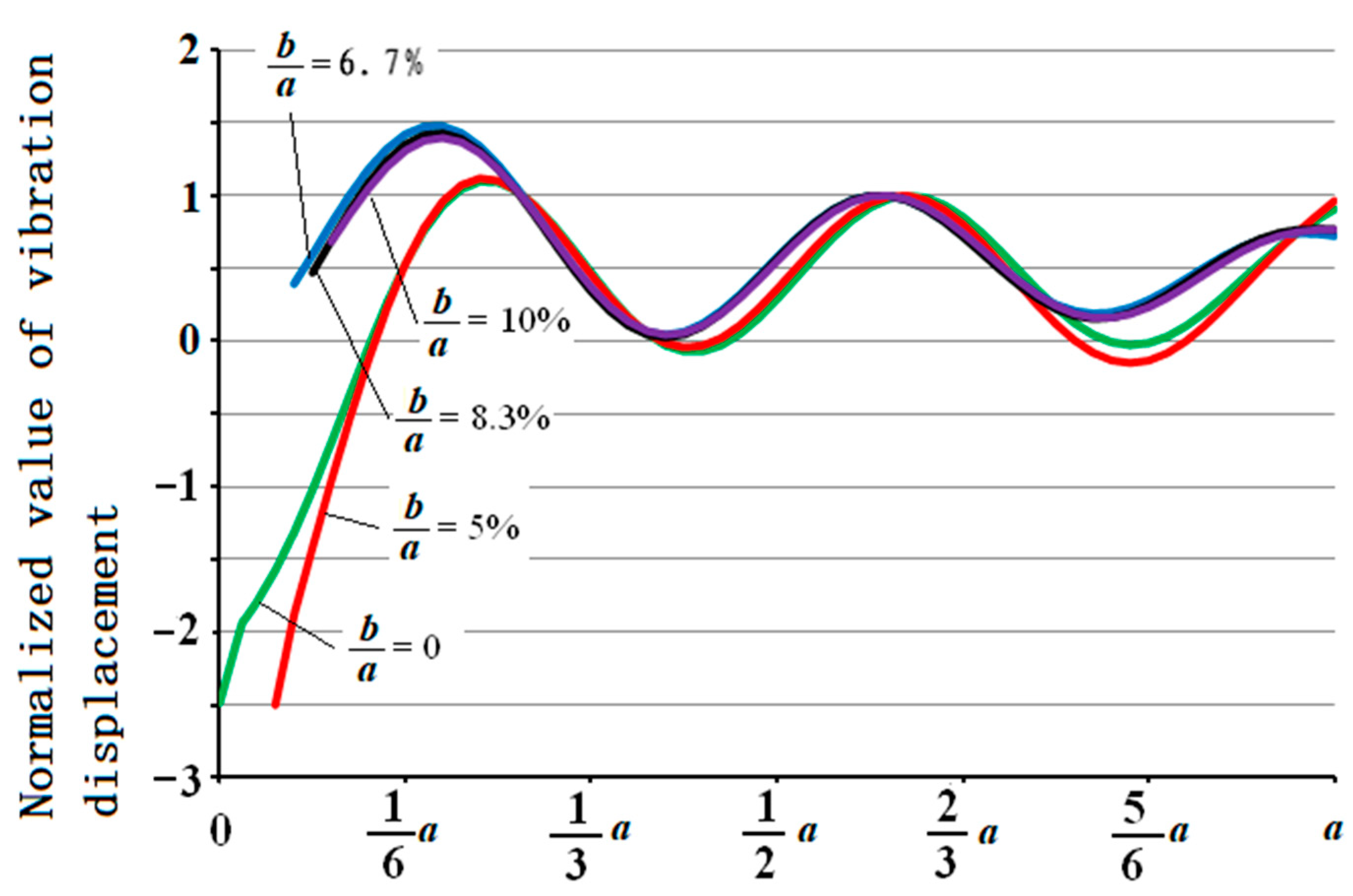
3.1. Influence of Center Hole Variation on Thickness Vibration Frequency

A hole was added at the center of the piezoelectric disc. Considering that it will decrease the power capacity of the transducer, the size of the center hole should not be too large. Figure 4 shows a piezoelectric ceramic wafer with a hole in the center.
As can be seen from Figure 2, the vibration displacement of the center of the piezoelectric disc at the thickness vibration frequency is the largest. The particle vibration direction at the center is opposite to the vibration direction elsewhere, which affects the radiated sound performance of the disc piezoelectric vibrator as the functional element of the high-frequency transducer. Because the vibration phase at the center is opposite to that at other parts, at the distance of the sound field, the sound pressure generated at the center and the sound pressure generated at other parts offset each other, reducing the radiated sound energy of the disc transducer.
The piezoelectric disc with a hole in the center can make the thickness vibration pure. Compared with the piezoelectric disc without a hole, the piezoelectric disc with a hole adds a parameter to adjust the radial high-order modal frequency. By changing the size of the central hole, the radial high-order frequency can be separated from the fundamental frequency of thickness vibration, so as to reduce the influence of radial high-order frequency on the fundamental frequency of thickness vibration. In this paper, the conductance frequency response curve of piezoelectric ceramic disc with diameter of 60 mm, thickness of 10 mm, central hole size of 5 mm and material of pzt41 in the range of thickness vibration frequency is calculated. Compared with the piezoelectric ceramic wafer with no hole in the center and the same diameter, thickness and material, it is found that the thickness resonance frequency of the piezoelectric wafer with a hole is very obvious, the conductivity value increases obviously, and the conductivity value of other coupling resonance frequencies decreases. As shown in Figure 5. At the same time, the vibration shape of piezoelectric disc can be improved.
The piezoelectric disc with a hole in the center can also improve the sound energy radiated by the disc transducer and optimize the thickness vibration mode. Figure 6 simulates and calculates the vibration mode at the thickness vibration frequency of the circular plate with a hole. It can be seen from the figure that the amplitude of the vibrator surface is relatively more uniform than that of the central nonporous piezoelectric circular plate, and the amplitude fluctuation is reduced.
The influence of the change of the center hole on the radial high-order mode and the vibration frequency of the thickness is shown in Table 2.
In Table 2, the numerical value in Table 2 is the ratio of resonance frequency and thickness vibration fundamental frequency calculated by simulation when the diameter a and thickness t are fixed and the center hole size is changed. With the increase of inner diameter, coupling mode 3 and 4 are gradually coupled into one mode, and the resonance frequency is gradually close to the same.

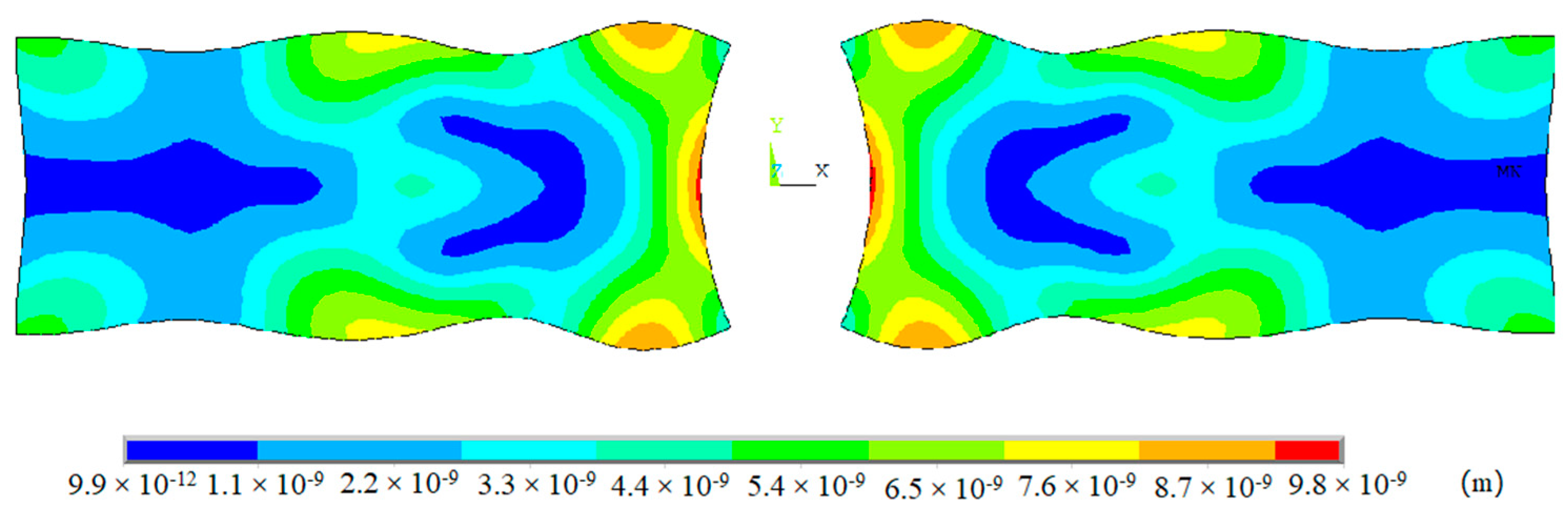
3.2. Piezoelectric Disc Transduce with a Center Hole

The center hole will affect the surface vibration displacement, impedance characteristics and electroacoustic performance of the piezoelectric disc transducer. The optimal design scheme of the transducer can only be obtained by comprehensively considering various factors. When the radius of the central hole is a0 and the ratio of a0/a is different, the modal analysis displacement curve in the normal direction of the particle vibration on the surface of the piezoelectric disc at the thickness vibration frequency point is shown in Figure 7.
Regarding the normal vibration displacement curves of piezoelectric disc with different central hole sizes, each curve is normalized by the displacement abdomen between 1/2a and 2/3a. It can be seen from the figure that regardless of whether there is a hole in the center of the piezoelectric disc, at the thickness vibration frequency, the vibration displacement of each particle on its surface is not of uniform amplitude, but has a wave crest and a wave trough. This is equivalent to weighting the surface of the disc plate with uniform vibration, and has an important influence on the directional open angle and sidelobe level of the transducer. When a0/a ratio is in a certain range, the vibration displacement of the transducer can be improved, the inverse vibration region can be eliminated, and the radiated sound performance of the transducer can be improved.

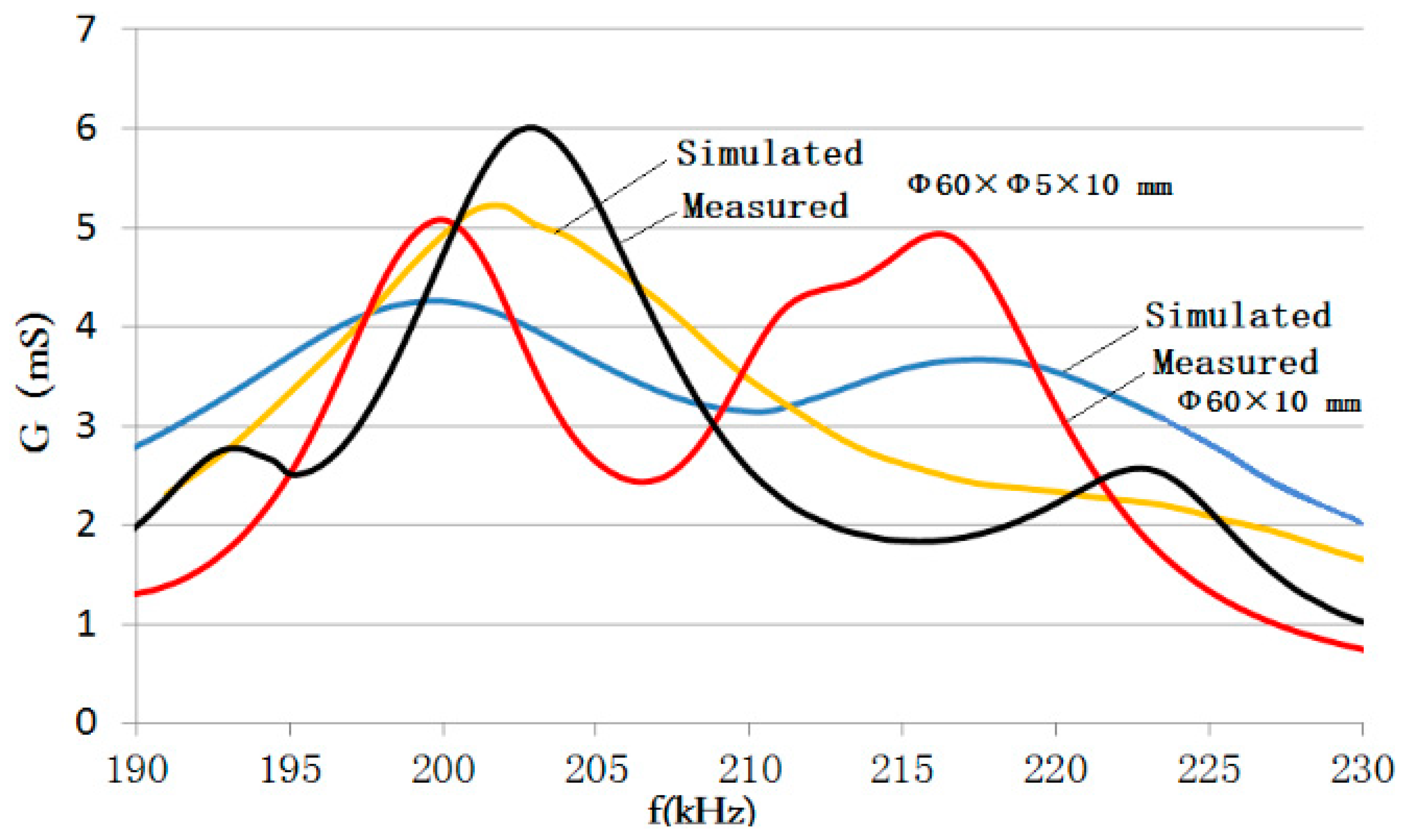
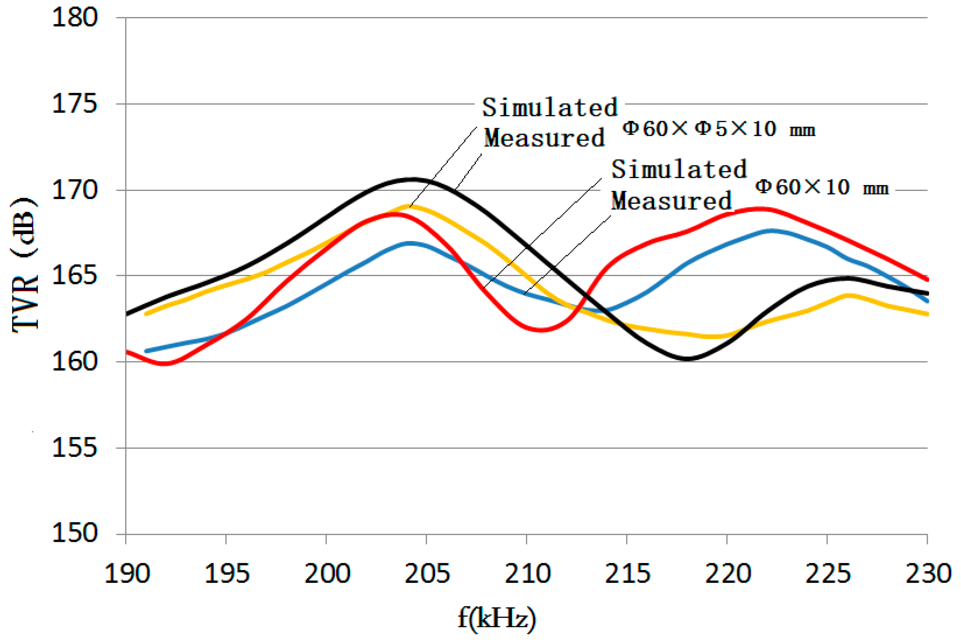
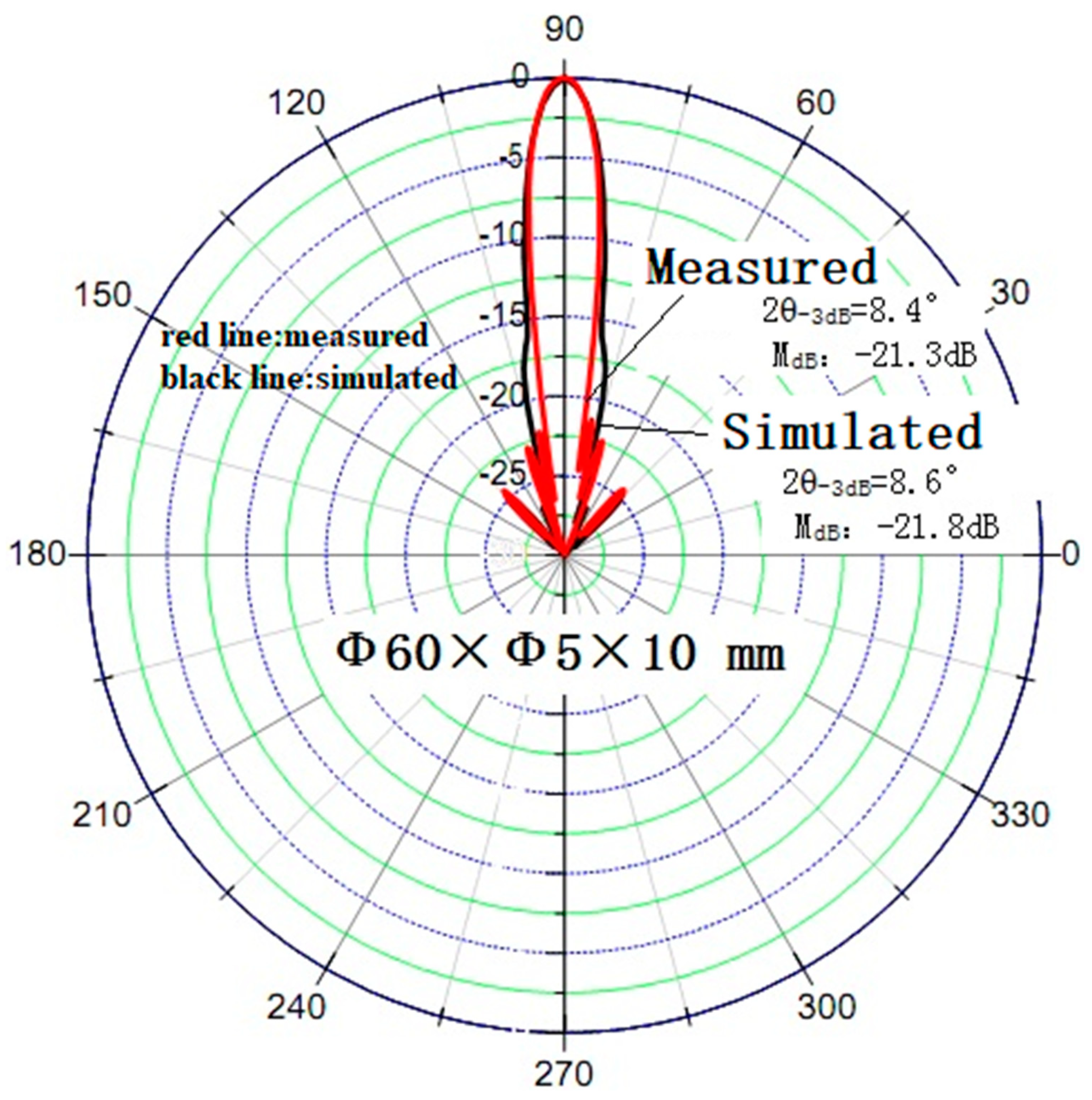
4. Experimental Verification

In this paper, a piezoelectric disc transducer with a hole in the center and a conventional piezoelectric disc transducer are designed. The size of the piezoelectric disc transducer with a hole in the center is Φ60 × Φ5 × 10 mm, and that of the conventional piezoelectric disc transducer is Φ60 × 10 mm. Figure 8 and Figure 9 are the simulation and measurement results of the underwater conductivity characteristics and transmission voltage response level curves of the two transducers, respectively. The results show that there is only one strong main peak in the water conductivity curve and transmission voltage response curve of the piezoelectric disc transducer with a hole in the center at the thickness vibration frequency, and the conductance value and transmission voltage response level value increase, and the response increase value is consistent with the simulation results, which shows that the simulation results are effective and accurate.
Figure 10 shows the directivity of the high-frequency transducers with a center hole at 200 kHz. Through comparative analysis, the measured thickness of the vibration transducer with a 5 mm disc hole in the center increases the main lobe beam width by 0.7° and decreases the sidelobe level by 1.3 dB.

5. Conclusions

Due to the high-frequency of the thickness vibration mode of the piezoelectric wafer, the vibration shape is very complex due to the coupling effect of the radial high-order mode, the thickness shear vibration modes, and other modes. In this paper, through the theoretical and simulation calculation of the vibration mode and coupling vibration frequency of the piezoelectric vibrator, the frequency optimization research, decoupling method and experimental verification were carried out. The low-sidelobe high-frequency transducer was obtained by adjusting the central hole size of the perforated piezoelectric ceramic wafer. The simulation analysis and experimental results show that the central hole has a simple but effective decoupling effect on the modal vibration of the circular high-frequency transducer, leading to the improvement of both the transmitting ability and directivity of the circular transducer. With the increase of the inner diameter of the hole in the center, the normal inverse vibration displacement of the disc surface disappears, the thickness vibration mode is gradually weakened by the coupling effect, and the acoustic emission ability and sidelobe level of the transducer are improved. This simple method provides technical support for the design of high-frequency transducers.

Author Contributions

Conceptualization, H.Z. and H.L.; methodology, Y.W.; software, J.B.; formal analysis, Z.L.; investigation, H.Z.; resources, J.C.; writing—original draft preparation, H.Z.; writing—review and editing, J.C.; funding acquisition, H.Z. All authors have read and agreed to the published version of the manuscript.

Funding

This research was funded by National Natural Science Foundation of China, grant number 41906175‚ U1806221, U1809212, U1906218.

Institutional Review Board Statement

Not applicable.

Informed Consent Statement

Not applicable.

Data Availability Statement

Not applicable.

Conflicts of Interest

The authors declare no conflict of interest.

References

  1. Wu, P.R.; Liu, Z.J.; Wang, Y.; Yue, Y.T. A high frequency underwater transducer curved array. Tech. Acoust. 2012, 31, 628–630. [Google Scholar]
  2. Li, H.; Deng, Z.D.; Carlson, T.J. Piezoelectric Materials Used in Underwater Acoustic Transducers. Sens. Lett. 2012, 10, 679–697. [Google Scholar] [CrossRef] [Green Version]
  3. Mariello, M.; Fachechi, L.; Guido, F.; De Vittorio, M. Multifunctional sub-100 µm thickness flexible piezo/triboelectric hybrid water energy harvester based on biocompatible AlN and soft parylene C-PDMS-Ecoflex™. Nano Energy 2021, 83, 105811. [Google Scholar] [CrossRef]
  4. Mariello, M.; Guido, F.; Mastronardi, V.M.; Todaro, M.T.; Desmaële, D.; De Vittorio, M. Nanogenerators for harvesting mechanical energy conveyed by liquids. Nano Energy 2019, 57, 141–156. [Google Scholar] [CrossRef]
  5. Wang, S.; Zhang, T.; Li, K.; Ma, S.; Chen, M.; Lu, P.; Wei, L. Flexible Piezoelectric Fibers for Acoustic Sensing and Positioning. Adv. Electron. Mater. 2017, 3, 1600449. [Google Scholar] [CrossRef]
  6. Mo, X. Research Progress and Opportunities of Underwater Acoustic Transducer Technology in China. Progress and Opportunities of Underwater Transducers in China. Chin. Acad. Sci. 2019, 34, 272–282. [Google Scholar]
  7. Zhou, L.; Hu, Q. Review of Hydroacoustic Emission Transducer Technology. J. Harbin Eng. Univ. 2010, 7, 120–125. [Google Scholar]
  8. Zhang, P.; Zhang, Z. Piezoelectric Measurement; National Defence Industry Press: Beijing, China, 1983. [Google Scholar]
  9. Mori, E.; Iton, K.; Imamura, A. Analysis of a short column vibrator by Apparent Elasticity Method and its Application. Proc. Ultrason. Int. 1977, 36, 262–266. [Google Scholar]
  10. Lin, S.; Zhang, F. Multimode coupled vibration of piezoelectric ceramic disc oscillators. Acta Electron. Sin. 1994, 12, 64–69. [Google Scholar]
  11. Feng, F.; Shen, J.; Deng, J. Research on Two-dimensional Equivalent Circuit of Diameter-thickness Coupling Vibration of Piezoelectric Vibrator. Piezoelectr. Acousto-Opt. 2006, 28, 357–359. [Google Scholar]
  12. Li, M.; Zhang, H.; Ying, C. Analysis of voltage characteristics of thickness mode piezoelectric transducer. Acta Acoust. 1981, 5, 3–13. [Google Scholar]
  13. Guo, N.; Cawley, P. The finite element analgsis of the vibration characteristics of piezoelectric dics. J. Vib. 1992, 159, 115–138. [Google Scholar] [CrossRef]
  14. Kocbach, J. Finite Element Modeling of Ultrasonic Piezoelectric Transducers. Influence of Geometry and Material Parameters on Vibration, Response Functions and Radiated Field. Ph.D. Thesis, University of Bergen, Bergen, Norway, 2000. [Google Scholar]
  15. Lee, P.C.; Edwards, N.P.; Lin, W.S.; Syngellakis, S. Second-order theories for extensional vibrations of piezoelectric crystal plates and strips. IEEE Trans. Ultrason. Ferroelectr. Freq. Control 2002, 49, 1497. [Google Scholar] [CrossRef] [PubMed] [Green Version]
  16. Kybartas, D.; Lukoševičius, A. Analysis of coupled vibration modes in piezoelectric disks. Ultragarsas 2014, 53, 31–36. [Google Scholar]
  17. Hu, J.; Wang, C.; Li, J. The radiant properties of the coupled ultrasonic vibration system. J. Shaanxi Norm. Univ. 2015, 43, 30–35. [Google Scholar]
  18. Lee, H.; Singh, R. Comparison of two analytical methods used to calculate sound radiation from radial vibration modes of a thick annular disk. J. Sound Vib. 2005, 285, 1210–1216. [Google Scholar] [CrossRef]
  19. Storheim, E.; Lunde, P.; Vestrheim, M. Vibration of a baffled piezoelectric ceramic circular disk in lower radial modes, with near- and farfield sound radiation. Acoust. Soc. Am. J. 2017, 141, 3835–3836. [Google Scholar] [CrossRef]
  20. Chillara, V.K.; Davis, E.S.; Pantea, C.; Sinha, D.N. Ultrasonic Bessel beam generation from radial modes of piezoelectric discs. Ultrasonics 2019, 96, 140–148. [Google Scholar] [CrossRef] [PubMed]
Figure 1. Disc piezoelectric ceramics.
Actuators 10 00226 g001
Figure 2. (a) Three-dimensional vibration picture at 212.5 kHz. (b) The side views of a full scale at 212.5 kHz.
Actuators 10 00226 g002
Figure 3. Influence of different a/t ratios on sidelobe level of the circular transducer.
Actuators 10 00226 g003
Figure 4. Disc piezoelectric ceramics with a hole in the center.
Actuators 10 00226 g004
Figure 5. Conductivity curve of piezoelectric disc with a hole in the center.
Actuators 10 00226 g005
Figure 6. The side views of a full scale at 203 kHz of piezoelectric disc with a hole in the center.
Actuators 10 00226 g006
Figure 7. Normal vibration displacement curve with different b/a.
Actuators 10 00226 g007
Figure 8. Conductance curve of two transducers in water.
Actuators 10 00226 g008
Figure 9. Transmission voltage response curve of two transducers.
Actuators 10 00226 g009
Figure 10. 200 kHz directivity diagram of disc transducer with a center hole.
Actuators 10 00226 g010
Table 1. Comparison of the FEM simulation results and calculation results with (2) and (3) of the resonance frequency.
fr0
(kHz)
fr1
(kHz)
fr2
(kHz)
fx1
(kHz)
fr3
(kHz)
ft0
(kHz)
Formula results37.398.3156.3 213.8199.1
FEM Simulation results38.594.3131168200.1212.5
Table 2. Table of coupling frequency versus thickness frequency variation of inner diameter r when a/t = 6.
2b/2aCoupled Mode 1Coupled Mode 2Coupled Mode 3Coupled Mode 4Coupled Mode 5Coupled Mode 6
00.800.910.931.001.061.09
1.67%0.800.910.931.001.051.09
3.33%0.800.900.930.991.041.09
4.17%0.800.900.930.991.031.10
6.67%0.800.860.930.981.011.10
8.33%0.800.840.930.981.011.11
10.00%0.800.810.940.981.011.12
13.33%0.810.780.950.991.011.14
15.00%0.810.770.951.001.001.15
Publisher’s Note: MDPI stays neutral with regard to jurisdictional claims in published maps and institutional affiliations.

