
3-Bit Digital-to-Analog Converter with Mechanical Amplifier for Binary Encoded Large Displacements


Abstract
:1. Introduction
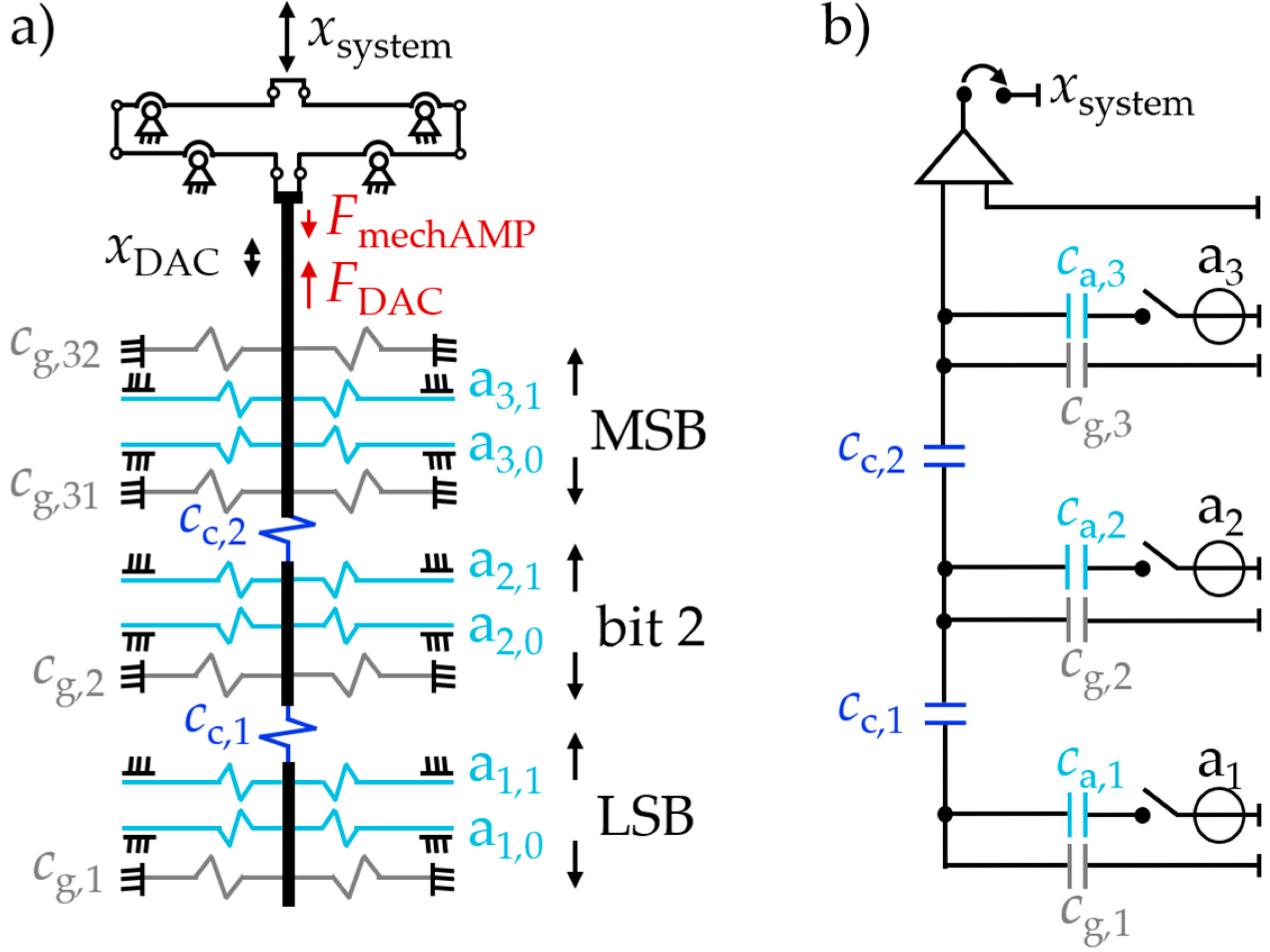
2. Concept
2.1. System Components
2.2. System Function
2.3. System Modeling and Simulation
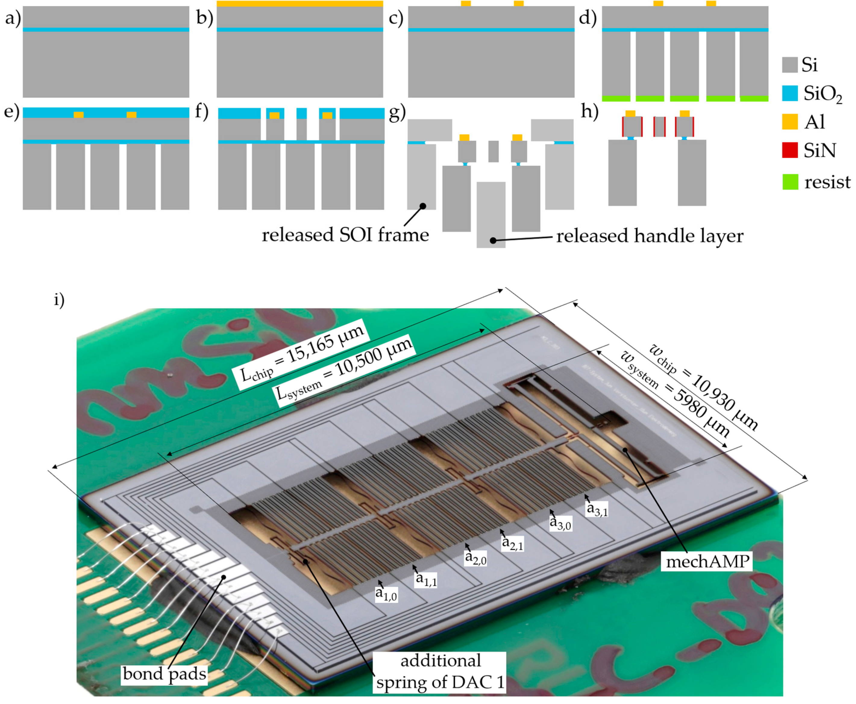
3. Fabrication
4. System Characterization Results
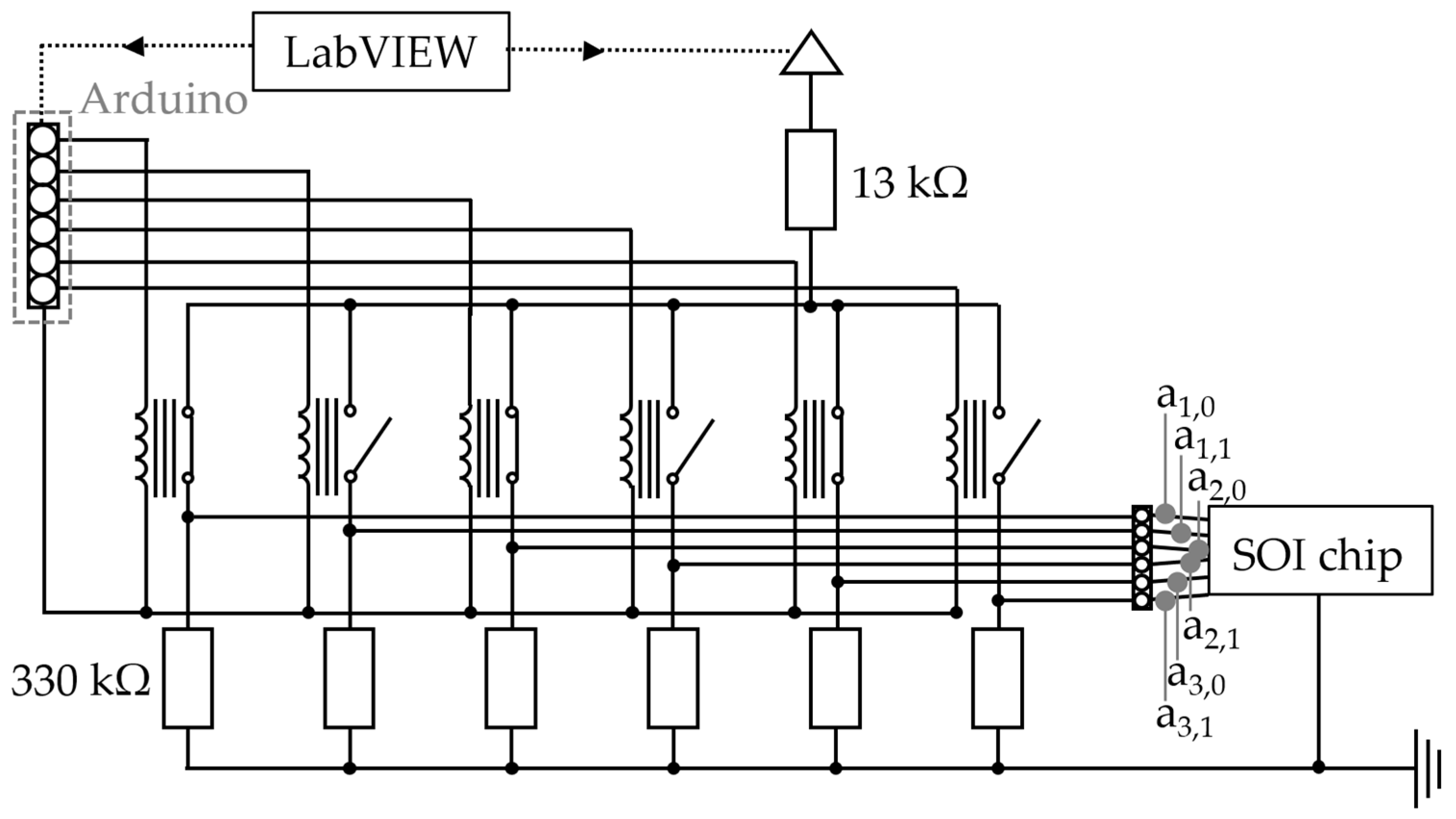
4.1. Experiment and Characterization Setup
4.2. Characterization of the System
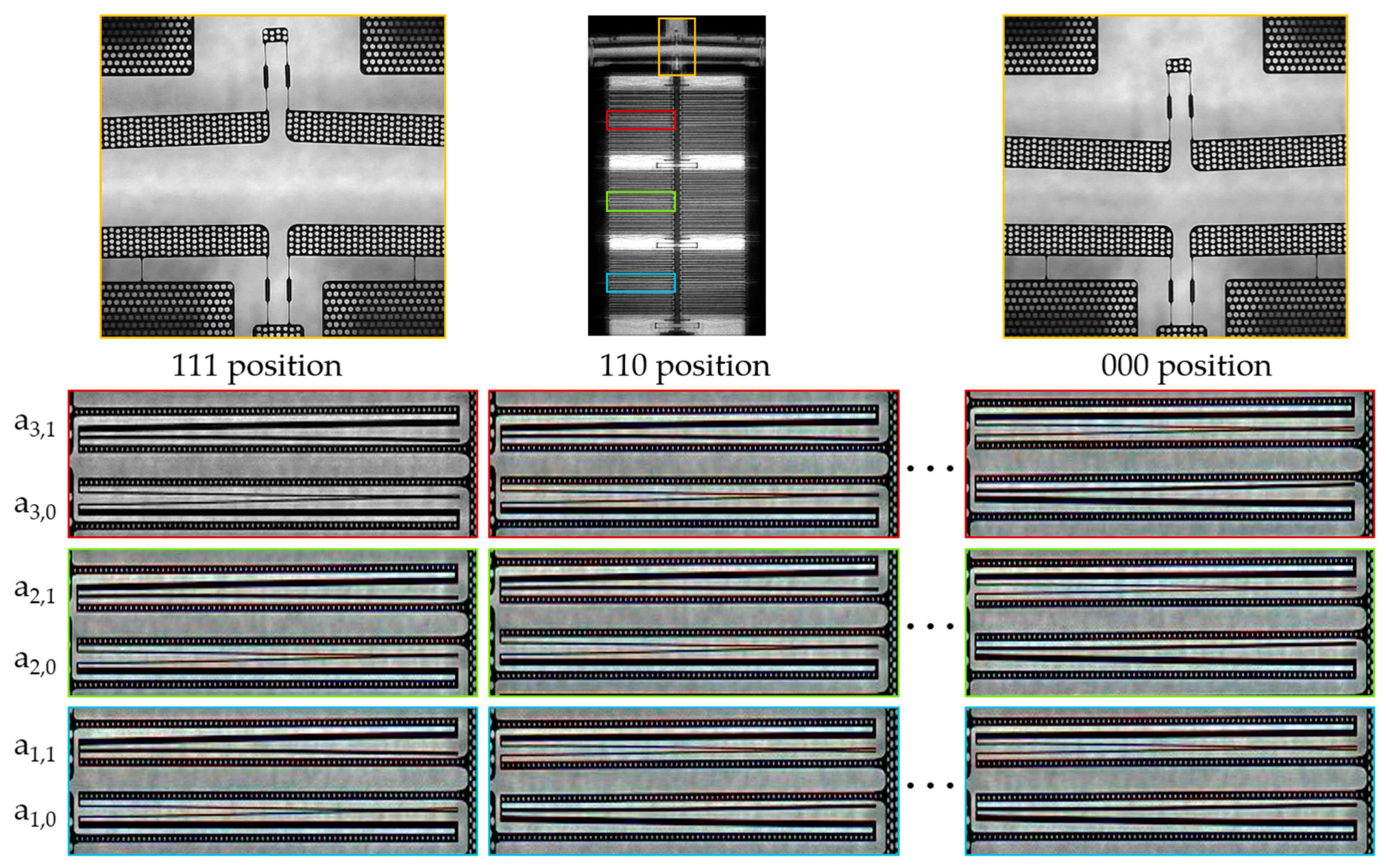
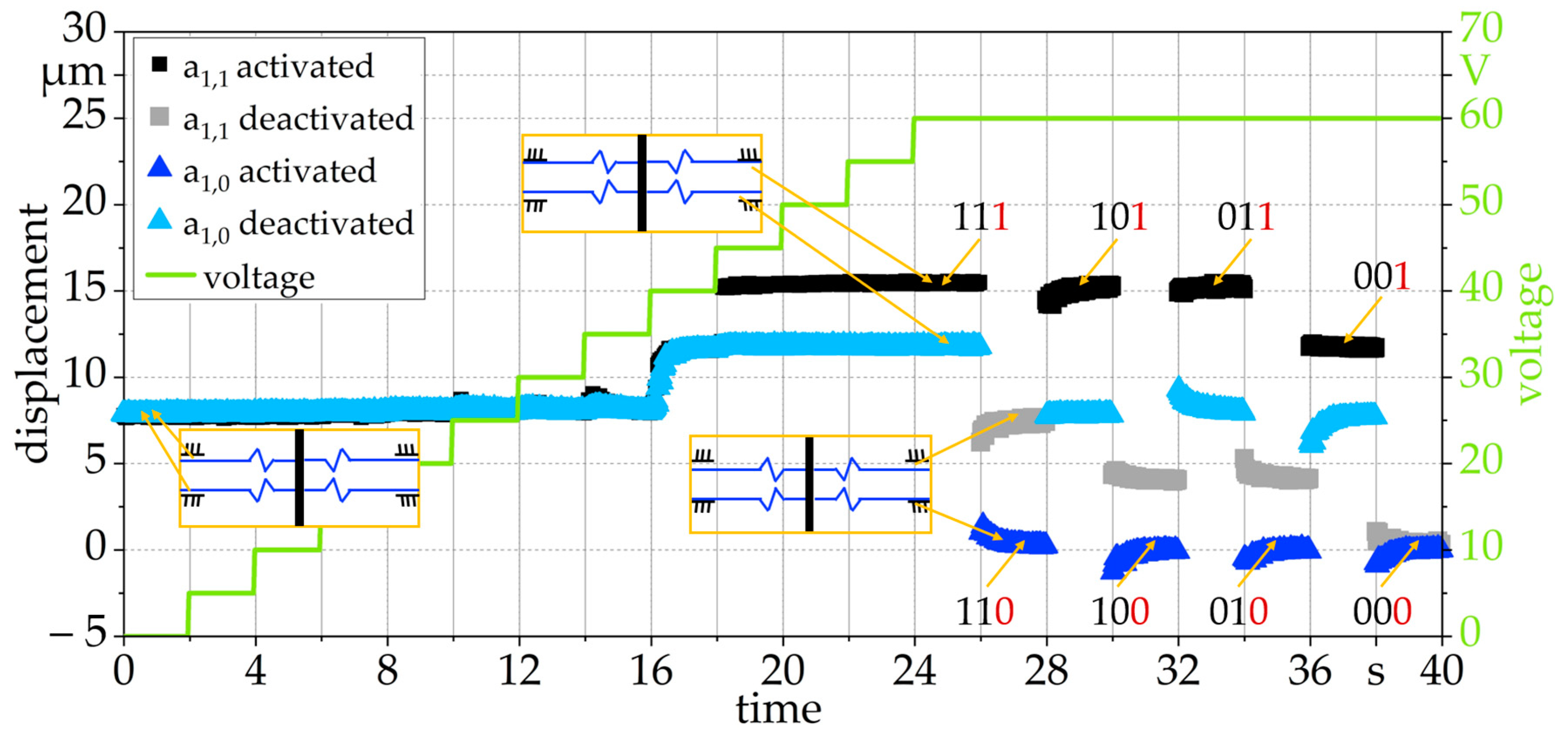
4.2.1. System Function Testing
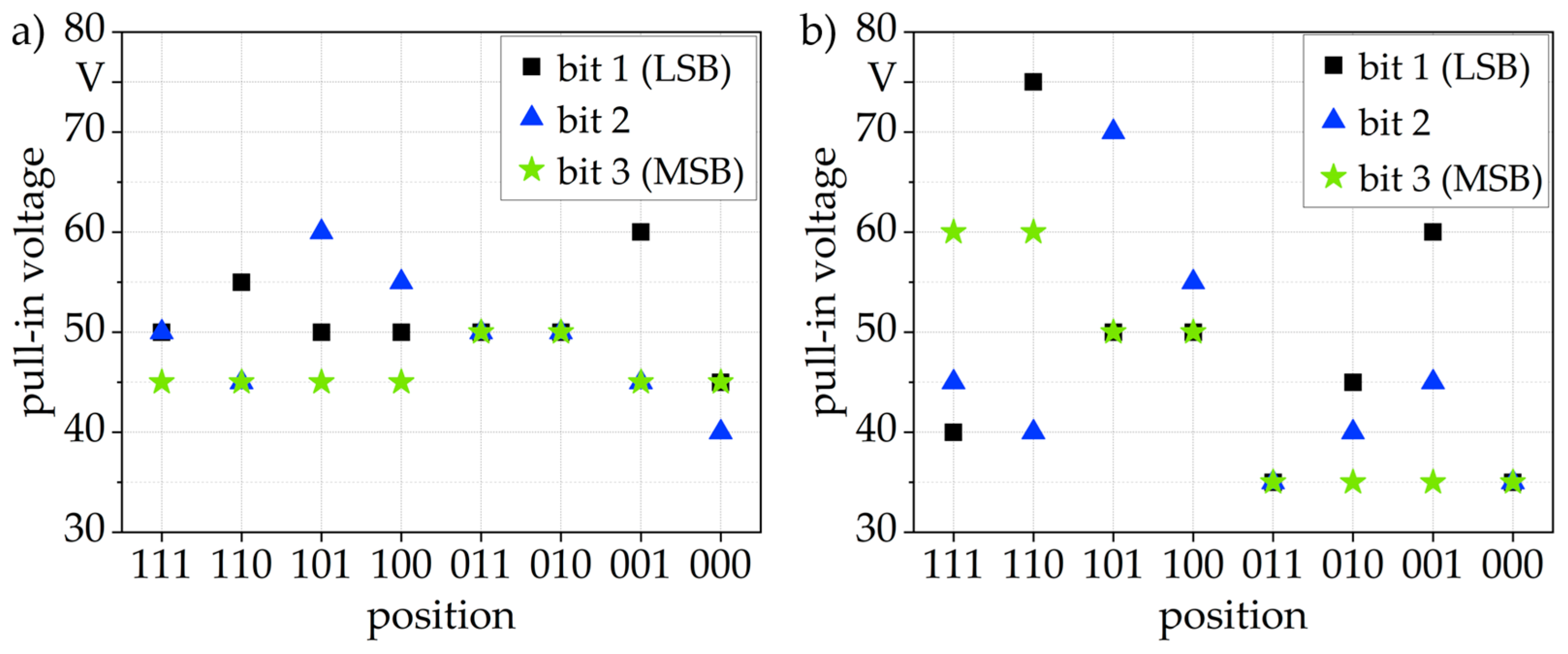
4.2.2. Characterization of the DAC
4.2.3. Characterization of the Combined DAC and mechAMP
4.2.4. Resonant Behavior, Switching Speed and Reliability of the System
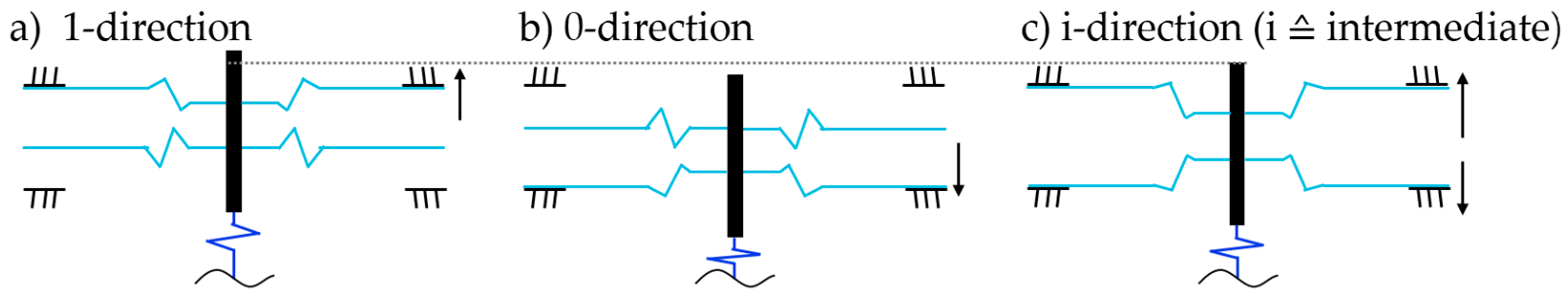
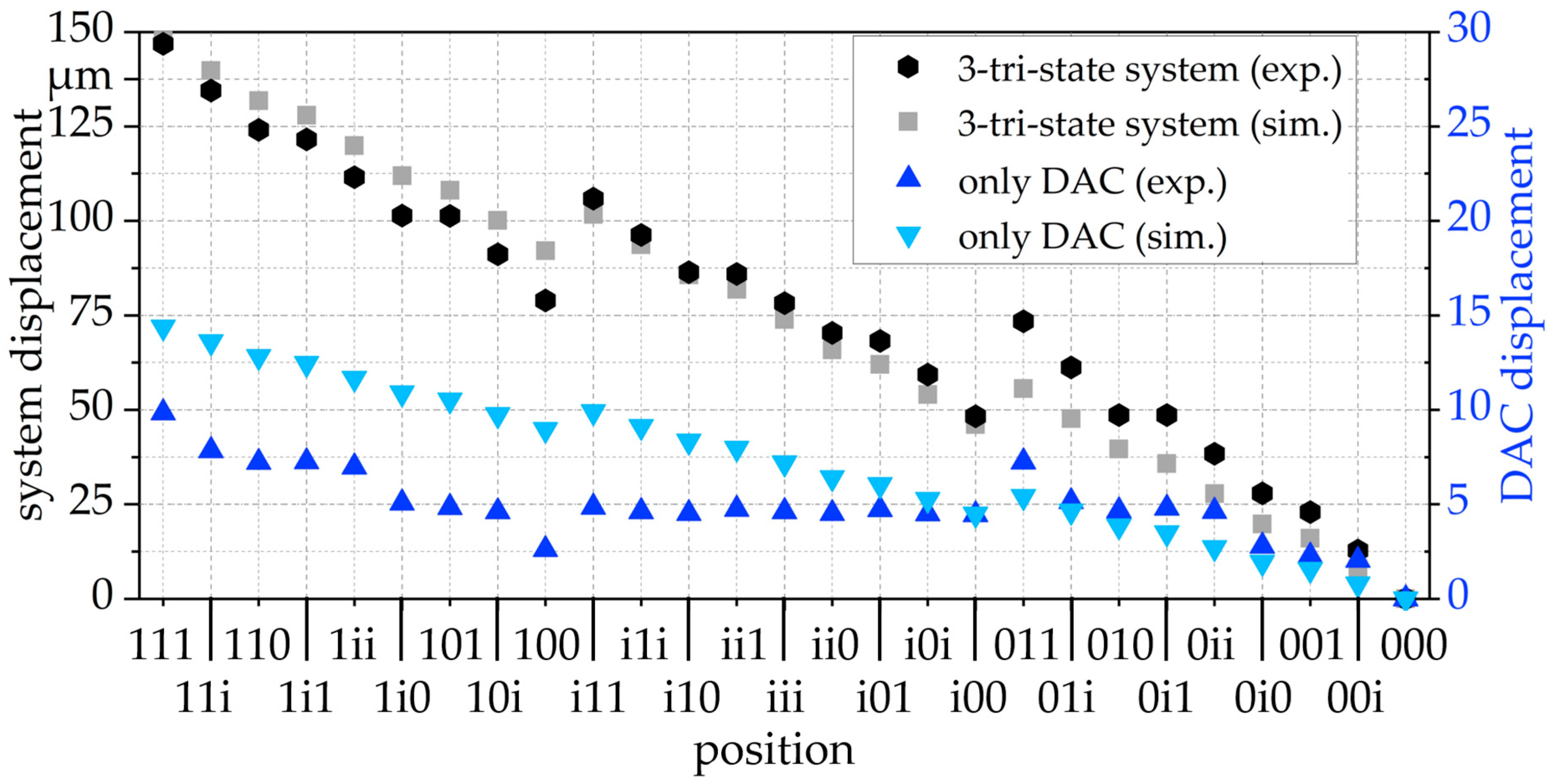
4.3. High-Resolution Mode Enlarging the System Positions from 23 = 8 to 33 = 27
5. Conclusions
Author Contributions
Funding
Data Availability Statement
Acknowledgments
Conflicts of Interest
References
- Fu, X.; Yang, F.; Liu, C.; Wu, X.; Cui, T.J. Terahertz Beam Steering Technologies: From Phased Arrays to Field-Programmable Metasurfaces. Adv. Opt. Mater. 2020, 8, 1900628. [Google Scholar] [CrossRef]
- Schmitt, L.; Schmitt, P.; Liu, X.; Czylwik, A.; Hoffmann, M. Micromechanical Reflect-Array for THz Radar Beam Steering based on a Mechanical D/A Converter and a Mechanical Amplifier. In Proceedings of the 2020 Third International Workshop on Mobile Terahertz Systems (IWMTS), Essen, Germany, 1–2 July 2020. [Google Scholar]
- Liu, X.; Samfaß, L.; Kolpatzeck, K.; Häring, L.; Balzer, J.C.; Hoffmann, M.; Czylwik, A. Terahertz Beam Steering Concept Based on a MEMS-Reconfigurable Reflection Grating. Sensors 2020, 20, 2874. [Google Scholar] [CrossRef] [PubMed]
- Sarajlic, E.; Collard, D.; Toshiyoshi, H.; Fujita, H. 12-bit microelectromechanical digital-to-analog converter of displacement: Design, fabrication and characterization. In Proceedings of the 2007 IEEE 20th International Conference on Micro Electro Mechanical Systems (MEMS), Hyogo, Japan, 21–25 January 2007. [Google Scholar]
- Zhou, G.; Logeeswaran, V.J.; Fook, S.C. An open-loop nano-positioning micromechanical digital-to-analog converter for grating light modulation. IEEE Photonics Technol. Lett. 2005, 17, 1010–1012. [Google Scholar] [CrossRef]
- Liao, H.-H.; Yang, Y.-J. A micromirror module using a MEMS digital-to-analog converter and its application for optical surface profiling. J. Micromech. Microeng. 2010, 20, 105009. [Google Scholar] [CrossRef]
- Richard, Y.; Conant, R.A.; Pister, K.S.J. Mechanical digital-to-analog converters. In Proceedings of the Tenth International Solid-State Sensors and Actuators Conference, Sendai, Japan, 7–10 June 1999. [Google Scholar]
- Liu, Q.; Huang, Q.-A. Design and finite element analysis of weighted-stiffness microelectromechanical digital-to-analogue converters. Electron. Lett. 2001, 37, 755–756. [Google Scholar] [CrossRef]
- Pandiyan, P.; Uma, G.; Umapathy, M. Design and simulation of MEMS-based digital-to-analog converters for in-plane actuation. Arab. J. Sci. Eng. 2017, 42, 4991–5001. [Google Scholar] [CrossRef]
- Toshiyoshi, H.; Kobayashi, D.; Mita, M.; Hashiguchi, G.; Fujita, H.; Endo, J.; Wada, Y. Microelectromechanical digital-to-analog converters of displacement for step motion actuators. J. Microelectromech. Syst. 2000, 9, 218–225. [Google Scholar] [CrossRef]
- Non-Member, E.S.; Collard, D.; Toshiyoshi, H.; Fujita, H. Design and modeling of compliant micromechanism for mechanical digital-to-analog conversion of displacement. IEEJ Trans. Electr. Electron. Eng. 2007, 2, 357–364. [Google Scholar]
- Schmitt, P.; Hoffmann, M. Engineering a compliant mechanical amplifier for MEMS sensor applications. J. Microelectromech. Syst. 2020, 29, 214–227. [Google Scholar] [CrossRef]
- Martin, H.; Nüsse, D.; Voges, E. Electrostatic parallel-plate actuators with large deflections for use in optical moving-fibre switches. J. Micromech. Microeng. 2001, 11, 323. [Google Scholar]
- Schmitt, P.; Schmitt, L.; Tsivin, N.; Hoffmann, M. Highly Selective Guiding Springs for Large Displacements in Surface MEMS. J. Microelectromech. Syst. 2021, 30, 597–611. [Google Scholar]
- Schmitt, L.; Liu, X.; Czylwik, A.; Hoffmann, M. Design and fabrication of MEMS reflectors for THz reflect-arrays. In Proceedings of the 2021 Fourth International Workshop on Mobile Terahertz Systems (IWMTS), Duisburg, Germany, 5–7 July 2021. [Google Scholar]
- Ibrahim, S.; Zeimpekis, I.; Kraft, M. A dicing free SOI process for MEMS devices. Microelectron. Eng. 2012, 95, 121–129. [Google Scholar]
- Grade, J.D.; Jerman, H.; Kenny, T.W. Design of large deflection electrostatic actuators. J. Microelectromech. Syst. 2003, 12, 335–343. [Google Scholar] [CrossRef]


| Ref. | Actuation | No. of Bits | Maximum Stroke | Voltage |
|---|---|---|---|---|
| [7] | thermal | 3 | 5.8 µm | 5 V |
| [8] | electrothermal compliant | 4 | 3.75 µm | 5 V |
| [9] | electrothermal compliant | 4 | 44 µm/45 µm | 5 V/5 V |
| [10] | electrostatic (comb-drive) | 4 | 5.8 µm | 150 V |
| [4,11] | electrostatic (comb-drive) | 12 | 8.57 µm | 45 V |
| this work | electrostatic (bending-plate) | 3/3-tri-states | DAC + mechAMP: 149.5 µm only DAC: 21.4 µm | 60 V/75 V |
| System 1 (Figure 7i) | System 2 | ||
|---|---|---|---|
| DAC | version | DAC 1 | DAC 2 |
| xDAC,max | 17.8 µm | 19.8 µm | |
| step size | 2.5 ± 0.8 µm | 2.8 ± 0.4 µm | |
| mechAMP | version | mechAMP+ | mechAMP– |
| amplification ratio | 10.3 | 15.1 | |
| input stiffness | 44.7 µN | 127.4 µN | |
| DAC combined to mechAMP | xDAC,max | 14.0 µm | 11.1 µm |
| step size | 2.0 ± 0.7 µm | 1.6 ± 0.2 µm | |
| system | xsystem,max | 143.7 µm | 167.1 µm |
| step size | 20.5 ± 6.7 µm | 23.9 ± 3.1 µm | |
| system size | 10,500 × 5980 µm2 | 11,080 × 6144 µm2 | |
| chip size | 15,165 × 10,930 µm2 | 15,707 × 10,930 µm2 |
Publisher’s Note: MDPI stays neutral with regard to jurisdictional claims in published maps and institutional affiliations. |
© 2021 by the authors. Licensee MDPI, Basel, Switzerland. This article is an open access article distributed under the terms and conditions of the Creative Commons Attribution (CC BY) license (https://creativecommons.org/licenses/by/4.0/).
Share and Cite
Schmitt, L.; Schmitt, P.; Hoffmann, M. 3-Bit Digital-to-Analog Converter with Mechanical Amplifier for Binary Encoded Large Displacements. Actuators 2021, 10, 182. https://doi.org/10.3390/act10080182
Schmitt L, Schmitt P, Hoffmann M. 3-Bit Digital-to-Analog Converter with Mechanical Amplifier for Binary Encoded Large Displacements. Actuators. 2021; 10(8):182. https://doi.org/10.3390/act10080182
Chicago/Turabian StyleSchmitt, Lisa, Philip Schmitt, and Martin Hoffmann. 2021. "3-Bit Digital-to-Analog Converter with Mechanical Amplifier for Binary Encoded Large Displacements" Actuators 10, no. 8: 182. https://doi.org/10.3390/act10080182
APA StyleSchmitt, L., Schmitt, P., & Hoffmann, M. (2021). 3-Bit Digital-to-Analog Converter with Mechanical Amplifier for Binary Encoded Large Displacements. Actuators, 10(8), 182. https://doi.org/10.3390/act10080182