Article

Fabrication of a Polyimide Film Pneumatic Actuator by Molding and Welding Processes

1
Institute of Academic and Research, Okayama University, 1-1-1 Tsushima-naka, Kita-ku, Okayama 700-8530, Japan
2
Department of Mechanical Engineering, Saitama University, Shimo-Okubo 255, Sakura-ku, Saitama-shi 338-8570, Japan
*
Author to whom correspondence should be addressed.
Actuators 2021, 10(8), 177; https://doi.org/10.3390/act10080177
Submission received: 29 June 2021 / Revised: 25 July 2021 / Accepted: 28 July 2021 / Published: 30 July 2021
(This article belongs to the Special Issue Artificial Muscles and Soft Actuation)

Abstract

:
The bellows pneumatic actuator, which is made by folding a non-stretch film, has been proposed for various applications because it is easy to fabricate and is extremely thin and light. However, it has subpar durability performance, especially in the folded part of the film. In this study, we propose an actuator with a pod structure that possesses high design flexibility and is free from folding. A method of molding a pod structure on a polyimide film was established and a pneumatic actuator was successfully fabricated by using PI films. Two types of PI film pneumatic actuators with the same curvature, bellows type, and pod type were fabricated. Both were confirmed to have equivalent output characteristics. The bending angle and generated torque of the pod-structure actuator were 34° and 3.3 mNm, respectively. In addition, the pod structure has approximately twice the durability of the bellows structure. By using the fabrication method proposed in this paper, it is possible to realize an air chamber (i.e., an actuator) that has both high durability and bending motion.

1. Introduction

In the future, robots are expected to be active in the fields of medicine, agriculture, nursing care, and welfare. In these fields, robots need to operate in environments where fragile objects or objects of unknown shapes exist, such as human bodies or natural objects. Conventional highly rigid robots, which are mainly used in the industrial field, are often unsuitable for these tasks in terms of safety and shape adaptability. For these reasons, research on soft robots, which can ensure safety through mechanical compliance, has attracted attention.
In order to realize soft robots, pneumatic soft actuators have been investigated [1,2]. The softness of the actuators is attributed to the gas compressibility and softness of the material used to make the actuator. Currently, many types of pneumatic soft actuators have been researched and developed [3,4,5,6]. They have also been applied to robot arms and hands as a safe driving source [7,8,9,10,11].
Many of these studies were based on the use of rubber molding or rubber tubing [12,13]. The expansion and deformation of the rubber chamber caused by the application of gas pressure is controlled by structural and mechanical constraints and is used as an actuator [14,15,16,17,18]. The McKibben-type artificial muscle using a fiber constraint is one of the most popular ones [19,20]. By contrast, a pneumatic film actuator uses a non-stretchable film. Film actuators are extremely lightweight owing to the thinness of their constituent materials. In the standby state where no gas is applied, most of the actuator will only be as thick as a laminated film. Therefore, robots and machine elements that can be easily stacked and transported are expected to be realized by using film actuators [21,22]. The actuator can also be permanently installed without taking up much space by wrapping it around something or tucking it into a crevice. For this reason, the demand for an inflatable structure such as a film actuator is increasing not only in the aforementioned application fields but also in fields such as space development where lightness and portability are very important [23,24]. Our research proposes a new concept of robotics that consists of only film-like actuators and structures. The concept is named “Filmotics”, which is a compound of the words film and robotics.
Pneumatic actuators made of films can be classified into the following types: The first involves fabricating a simple balloon chamber and using its expansion and contraction as actuators. It has advantages including simple structure, high stability, and large displacement by stacking [25,26,27]. The second is an actuator that combines a simple balloon structure with another structure to convert the motion of the chamber. These include pneumatic artificial muscles made of a film with a sleeve attached around the balloon [28] and actuators that convert motion by integrating with the frame and linkage mechanisms that form the skeleton [29,30]. These actuators can be combined with different structures to create a wide variety of movements.
There is also a type in which the chamber itself creates motions other than expansion and contraction. In this type, the motion is realized by folding the film that constitutes the chamber [31]. This type is advantageous because it is simple to fabricate and can achieve bending and twisting motions without requiring any other mechanism. In our research, a bellows actuator has been realized by using polyimide films, which has high extreme environmental resistance [32]. This actuator has a minimum drive temperature that is much lower than previous soft actuators and can be driven at 78 K. However, as will be discussed in the next section, repeated durability remains an issue due to the unfolding behavior of the folded part and buckling deformation caused by geometric failure.
In order to solve this problem, this paper presents a method for realizing a pneumatic film actuator in which the air chamber itself performs the curving motion without folding. The actuator can be fabricated simply by designing an expansion shape to achieve the curving motion and by welding the molded film. The prototype actuator exhibits a performance equivalent to that of the previous bellows actuator and the durability has also been improved.

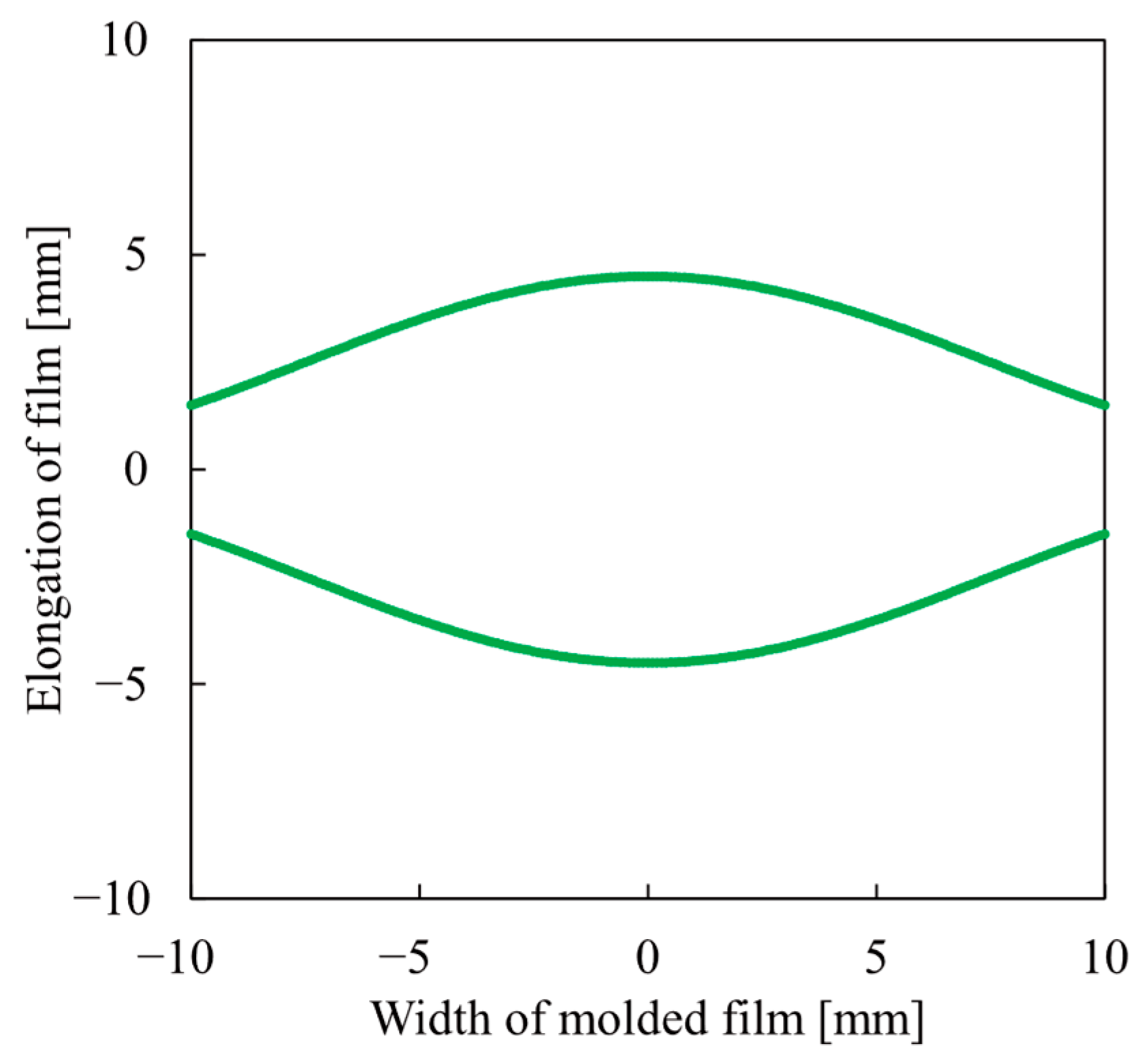
2. Design of Structure

A schematic view of the pneumatic bellows actuator of the PI films is shown in Figure 1. The actuator was fabricated by welding a bellows-folded film and an unformed film. The width of the folded film was longer than that of the unformed film and the folded film was welded in a curved shape in the width direction. When gas pressure is applied, the bellows expand and a difference in the path length between the upper and lower surfaces is created in the expanded state. This difference in path length causes the actuator to bend; the bending of the actuator is akin to the bending of a finger. This fabrication method is a very simple procedure and can realize an actuator for extreme environments.
However, when the actuator is driven cyclically for a long period of time, the local deformation and buckling deformation of the film increases owing to its non-stretching characteristics and fatigue failure progresses rapidly [33]. Especially in curved actuators with a bellows structure, there are many cases of failure from the center of the folded part, as shown in Figure 1b. The part is deformed the most during the transition to the unfolded state and undergoes buckling deformation. In addition, fatigue fractures are likely to occur because of the creases in this part. In other words, the current actuator structure is not entirely durable.
Therefore, instead of bellows folding, a structure is molded on the film, which creates a difference in path length when gas is applied. The difference in the path length should vary depending on the width direction of the actuator to prevent localized deformation. This means that the difference in the path of the upper and lower films caused by the unfolding of the bellows structure, which changes with position, is achieved by the structure. For this reason, the formed structure takes on the shape of a bean pod, as shown in Figure 2. This structure is termed the pod structure in this study.
The molded film and its dimensions are shown in Figure 3. When the actuator was fabricated, the upper film was curved and welded to a lower film. Therefore, the coordinate system of the molding film takes the u-axis as the axis along the curved upper film.
In the bellow structure, the longitudinal cross-sectional view of the curved state with air pressure applied is shown in Figure 4. The folded length at the point where the two films are welded together (welded area) is b and the length after the bellows expansion is λ b . The lengths of the upper and lower films must be similar in the unmold; therefore, λ 1 . The height from the welded area was h ( u ) and the height at the top of the shape was h U .
From the relationship between the cross-sectional shapes, the elongation length by molding, l λ ( u ) , is given by the following equation.
l λ ( u ) = ( λ 1 ) b h ( u ) h U .
The cross-section of the curved state with pneumatic pressure applied is shown in Figure 5. Due to the difference in width between the upper and lower films, the former covers a larger part of the circumference. The width of the upper film is w U , the width of the lower film is w L , the radius of the actuator is r, and the angle between the welded area and the bottom is ϕ L . The angle ϕ between the welded area and a point of the circumference of the circle with height h ( u ) is given by the following equation.
ϕ ( u ) = u r .
Here, h ( u ) is expressed as follows.
h ( u ) = r cos ϕ L r cos ( ϕ ( u ) + ϕ L ) .
The upper and lower film width ratios are defined as follows.
k w = w U w L .
From the relationship between circumference and film width, ϕ L is expressed as the following.
ϕ L = π k w + 1 .
By substituting and transforming the above equation, h ( u ) can be expressed as follows.
h ( u ) = 2 r sin ( u 2 r + π k w + 1 ) sin u 2 r .
Here, h U is calculated using the following equation.
h U = r + r cos ( π k w + 1 ) .
From the above, in order to realize a single shape, the elongation length l λ ( u ) of the pod structure can be expressed as the following.
l λ ( u ) = 2 ( λ 1 ) b 1 + cos ( π k w + 1 ) sin ( u 2 r + π k w + 1 ) sin u 2 r .
From Equation (8), the shape that will be elongated by molding can be obtained for fabricating an actuator that generates a curving motion using the difference in the length of the upper and lower film. By determining each parameter, the elongation required for the shape that can achieve the desired bending angle is calculated. In order to design a shape similar to the bellows structure, the number of folded films is three; thus, λ = 3 . The diameter of the actuator depends on w U and w L .
λ can take various values, unlike the bellows-type actuator. On the other hand, the upper limit of λ depends on the maximum elongation of the film to be molded. The maximum elongation was increased by heating the film to soften it. For this reason, molding should be performed under heated conditions.

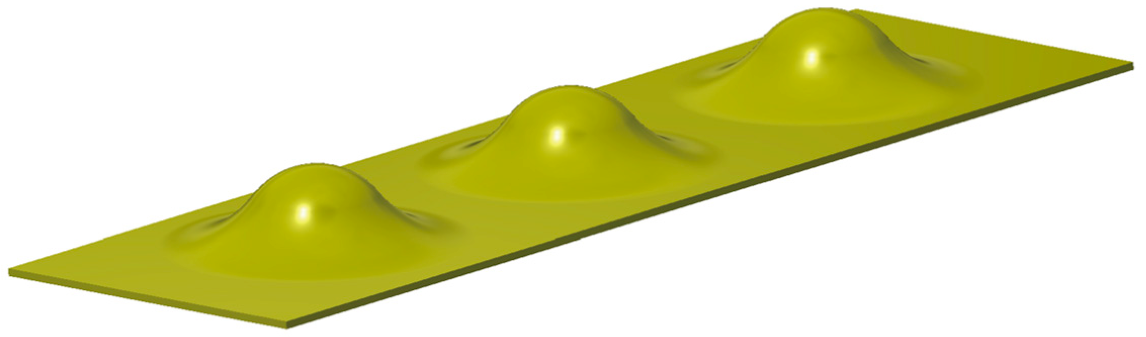
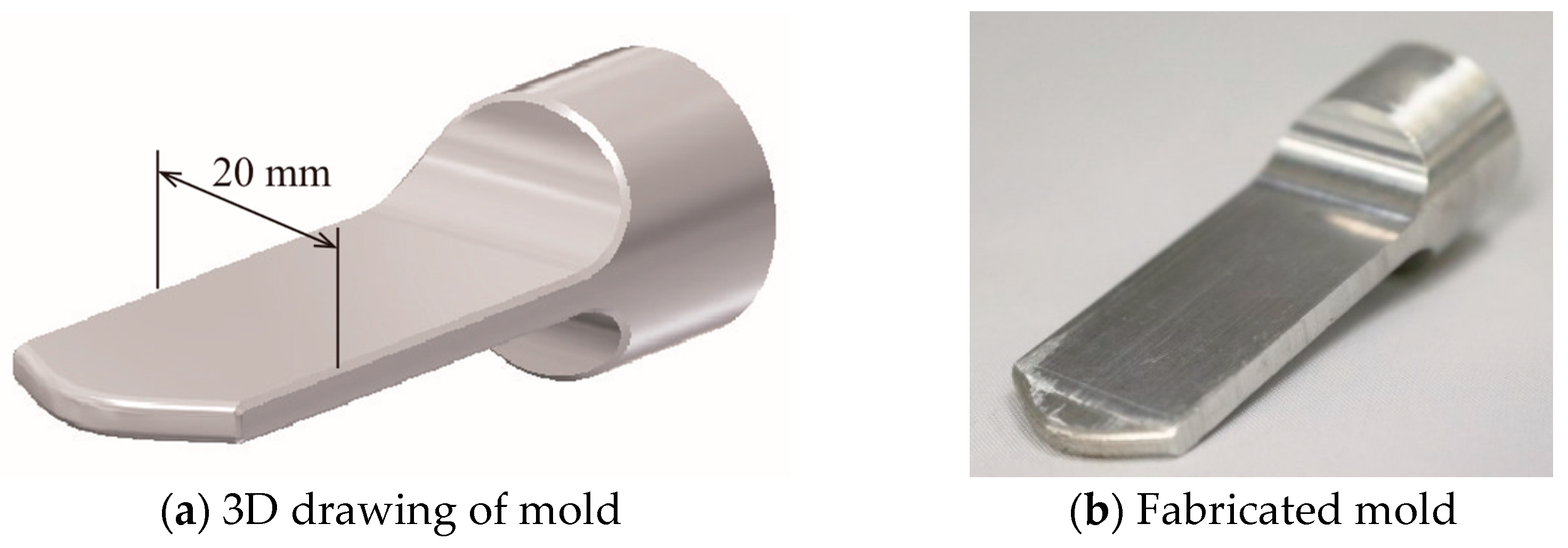
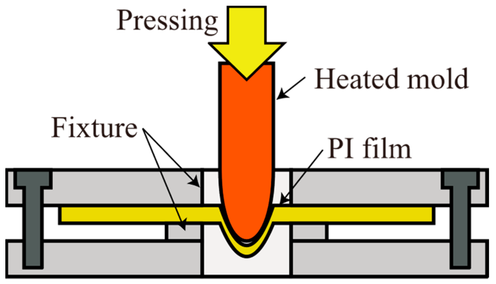
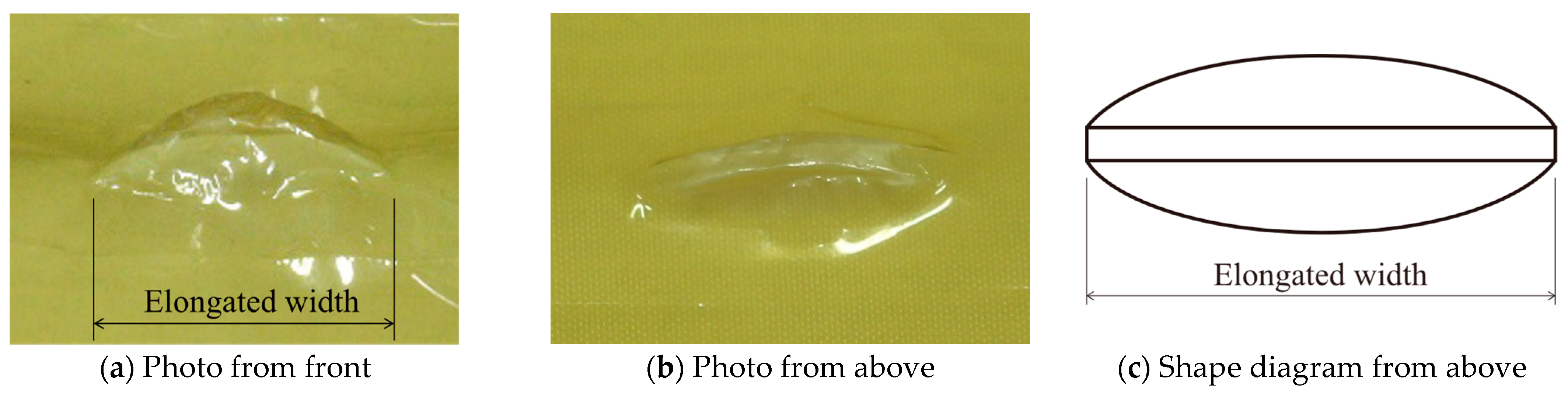
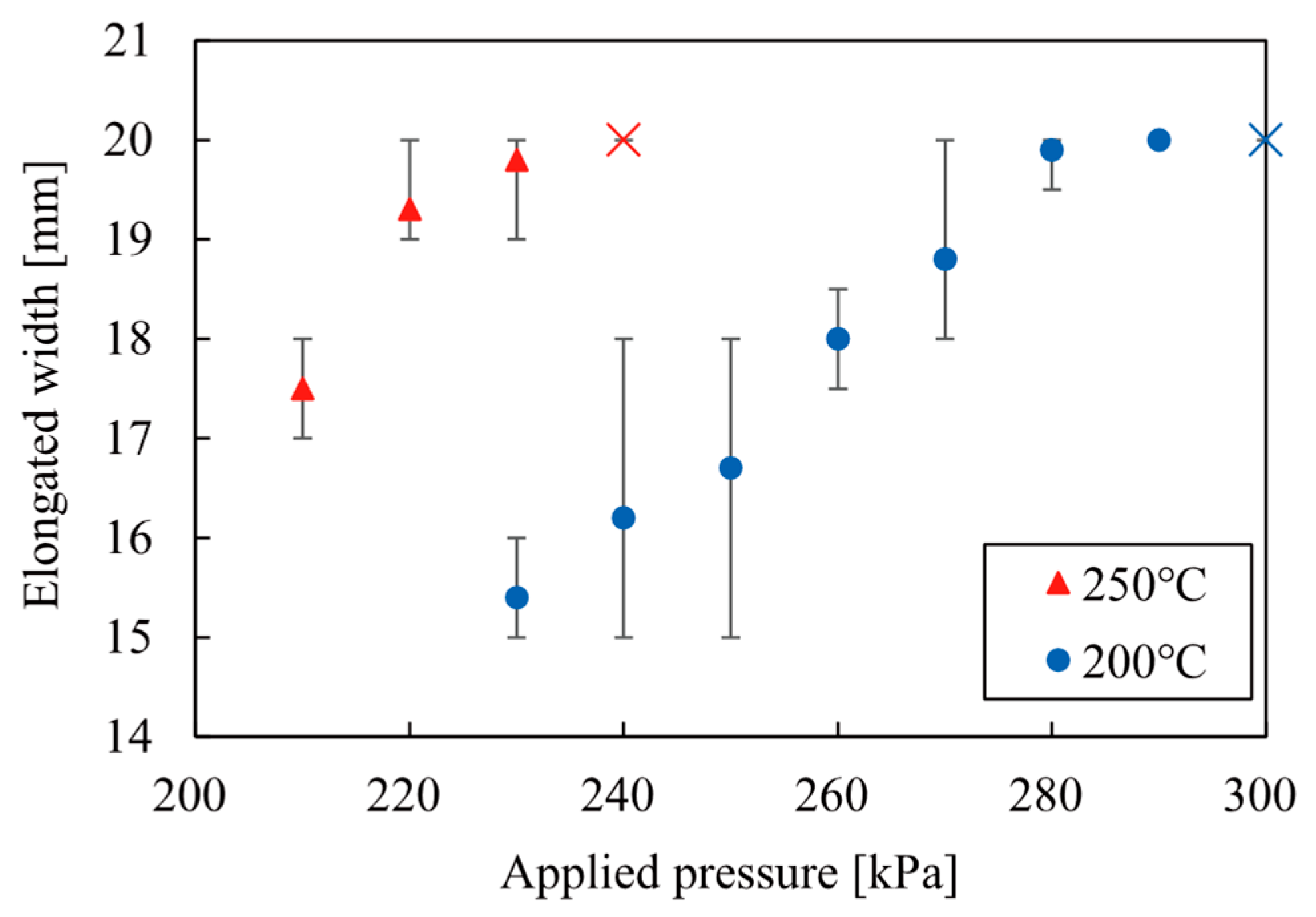
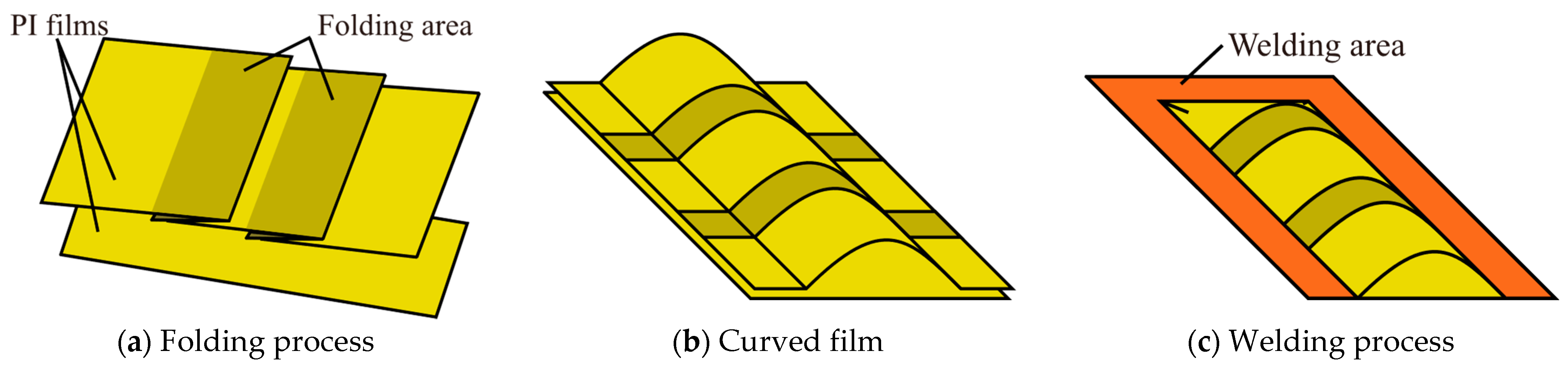
3. Fabrication of Pod Structure

The required elongation of the film was calculated based on the obtained design equation and a molding shape was designed. A molded shape in the direction of elongation is shown in Figure 6. The center of the shape was set as a zero point. Each parameter was set to the values listed in Table 1 to achieve a bending angle of 36°. A mold for the pod structure was fabricated based on the elongation.
The fabricated mold for PI film molding is shown in Figure 7. The mold was made of duralumin and the complex shape was shaped using a machining center. An outline of the molding method is shown in Figure 8. The PI film was held and positioned in the fixture. There is a hole in the center of the fixture through which the mold passes. The mold was heated to a high temperature and pressed against the film to form a PI film into the designed shape.
The molding machine is illustrated in Figure 9. The mold was attached to an air cylinder with a heater unit. A temperature sensor was installed in the heater unit and the mold was heated and controlled by using a heater unit. The air cylinder moves along a guide that determines the position of the fixture and presses the mold against the PI film. A limit is set by using a load cell and a spring to prevent the mold from being pushed beyond the designed amount.
The film in contact with the mold was stretched to fit its shape. Other areas were stretched under the conditions in which the film was most stable. In a mold with a curved tip, the width of the structure changes depending on the amount of push-in. If the mold is pushed too deeply, the film is stretched only in the depth direction out of the range of the mold.
As the temperature increases, the film softens and becomes easier to stretch with lesser force. The maximum stretch ratio of the films also increases. Therefore, the molding conditions were evaluated by molding the film at different molding temperatures and pressures and measuring the width of the molded film. In preliminary experiments, pyrolysis occurred below the glass transition temperature of the PI film because the mold was pressed for a long time. Therefore, the molding was performed below the glass transition temperature. The molding temperature was controlled to a constant value by a heater unit and the temperature of the mold was measured beforehand. The molding pressure on the film was adjusted by the pressure applied to the air cylinder.
The molded PI film and the measured elongated width are shown in Figure 10. The target width was set to 20 mm to match the fabricated mold. The relationship between the molded width, temperature, and applied pressure is shown in Figure 11. By applying pressure in excess of a certain value, a width of 20 mm was obtained, confirming that the film was molded correctly. The higher the temperature, the softer the film becomes, indicating that the film can be molded at a lower pressure. By contrast, increasing the temperature caused the film to change its properties and tears were more likely to occur. At pressures above 290 kPa, the shape was molded beyond the range of the mold. In this study, the molding conditions were set to 200 °C and 280 kPa.

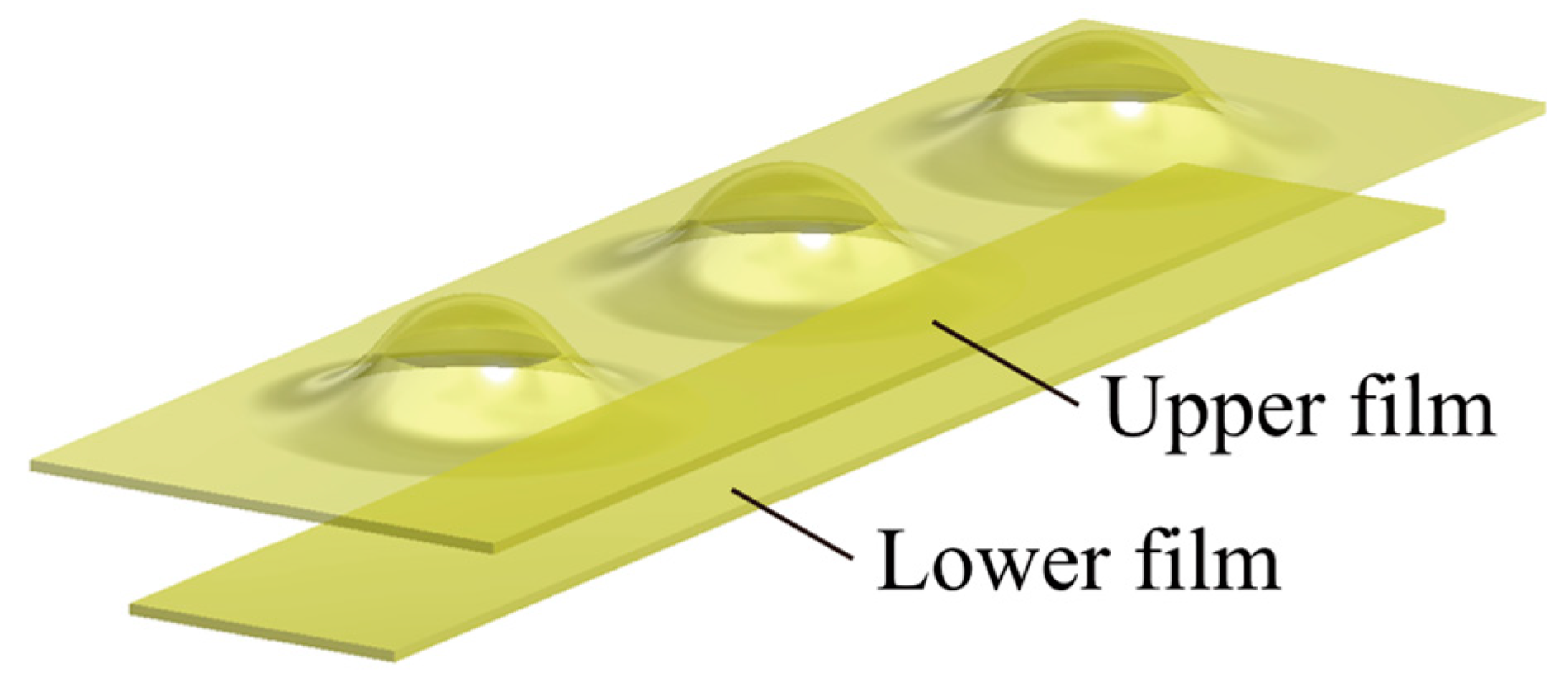
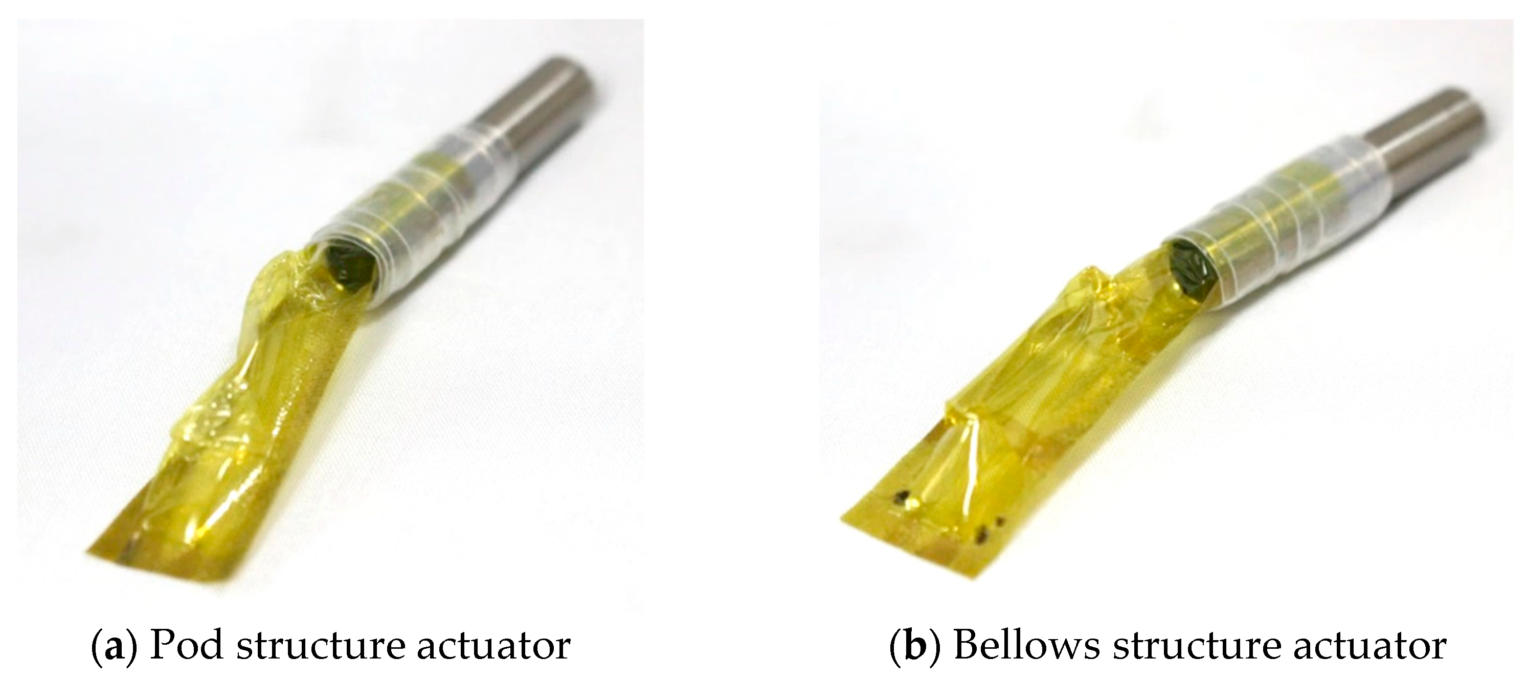
4. Fabrication of Actuator

A bellows-type actuator and pod-type actuator were fabricated. The fabrication of the actuator consists of two processes: fabrication of the air chamber and piping to the air chamber. Only the fabrication process of the chamber differed depending on the type of actuator. The chamber was fabricated by welding two 25 μm thick PI films. Each structure was fabricated by using an upper film.
In the case of the bellows structure, the film was folded, as shown in Figure 12. The chamber has three pleats, with the center pleat contributing to the bending motion. The pleats at both ends form the actuator when inflated. The folded length of the bending part (below the center) was 3 mm. The upper film was bent in the width direction and welded such that the diameter of the chamber was 8 mm. Then, one of the short sides was welded to fabricate a chamber. The widths of the upper and lower films were 20 and 10 mm, respectively.
In the case of the pod structure, three pods were molded on a single sheet using the mold described above, as shown in Figure 13. The molded film was bent in the width direction and welded to the lower film so that the diameter of the chamber was 8 mm. Then, one of the short sides was welded to fabricate a chamber.
A stainless-steel pipe with a diameter of 8 mm was inserted into each chamber and a heat-shrinkable tubing was used to clamp the pipes. The fabricated actuators are shown in Figure 14. Both actuators were cylindrical in shape, with a total length of 40 mm and a diameter of 8 mm.

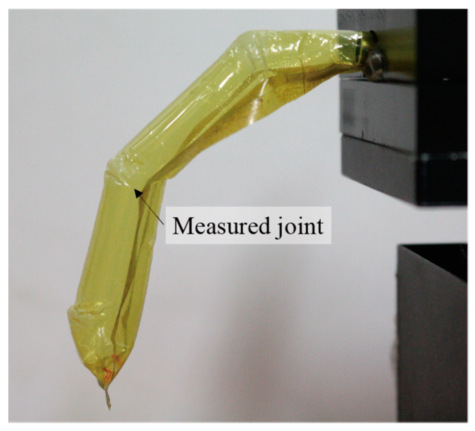
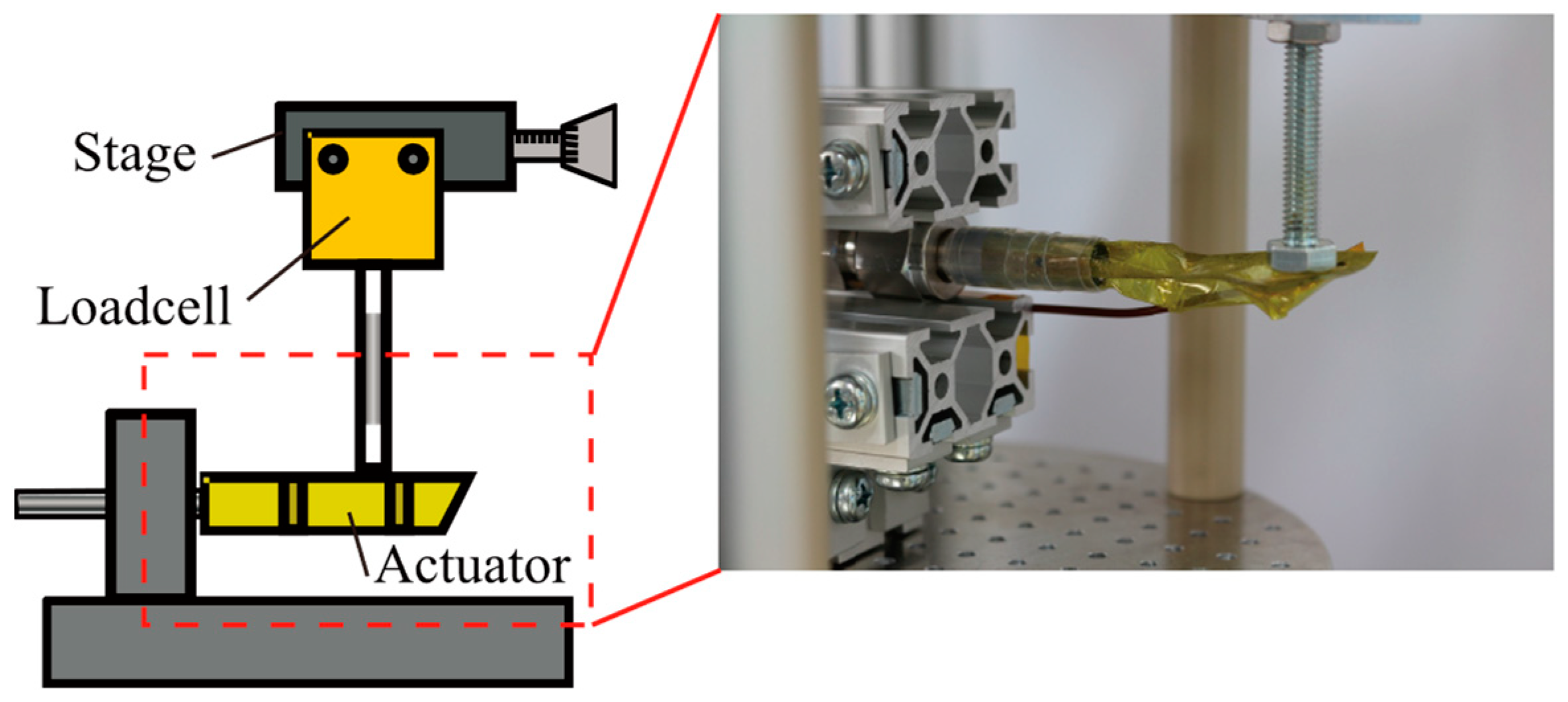
5. Evaluation of Actuators

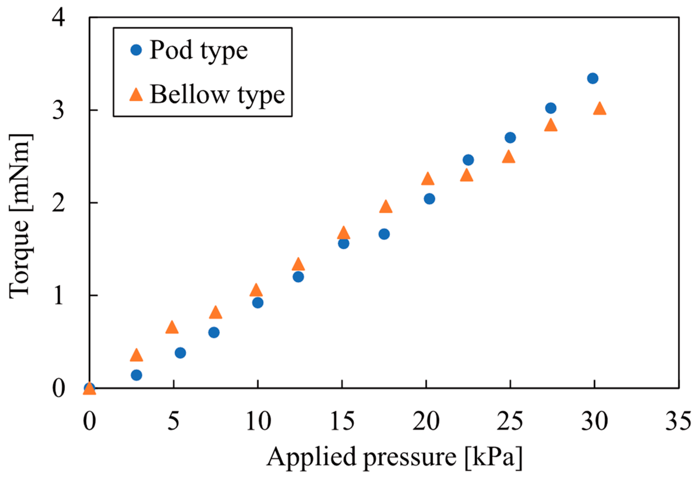
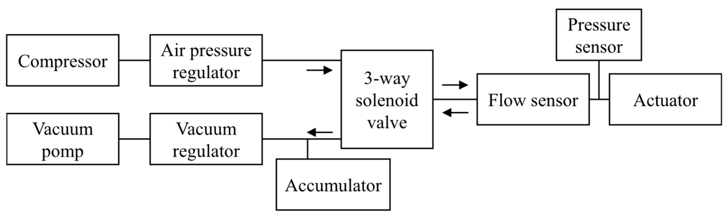
5.1. Output Characteristics

The deformation and generated torque of the two types of fabricated actuators were evaluated. The actuators consisted of a non-stretchable ultra-thin film. Therefore, the shape of the actuator deforms at a very low pressure and the shape is not uniquely determined in the low-pressure range. In addition, unlike rubber soft actuators, the deformation caused by the structure of this actuator is much larger than the deformation caused by the elastic deformation of the material. Moreover, the shape remains the same at pressures above a certain level. Therefore, the shape of the actuators was evaluated at an applied pressure higher than the pressure at which the deformation was completed.
The deformation of the pod structure actuator at an applied pressure of 30 kPa is shown in Figure 15. The bending angle of the central joint, which contributes only to the angular deformation, was 34°. The bending angle of the bellows actuator was 35° when the applied pressure was 10.7 kPa. Since the design value was 36°, the bending angle was achieved as designed.
The relationship between the applied pressure and the torque generated by the actuators in the displacement-constrained state was evaluated. Figure 16 shows a schematic diagram of the measurement system and measurement. The actuator was fixed to the apparatus at the piping section and a force gauge was pushed 20 mm from the joint center where the force was generated. The torque was calculated by multiplying the measured force with the distance of the joint center from the measurement point. The relationship between the applied pressure and the generated torque is shown in Figure 17. From these experimental results, it was confirmed that two different actuator structures with equivalent performances could be fabricated.

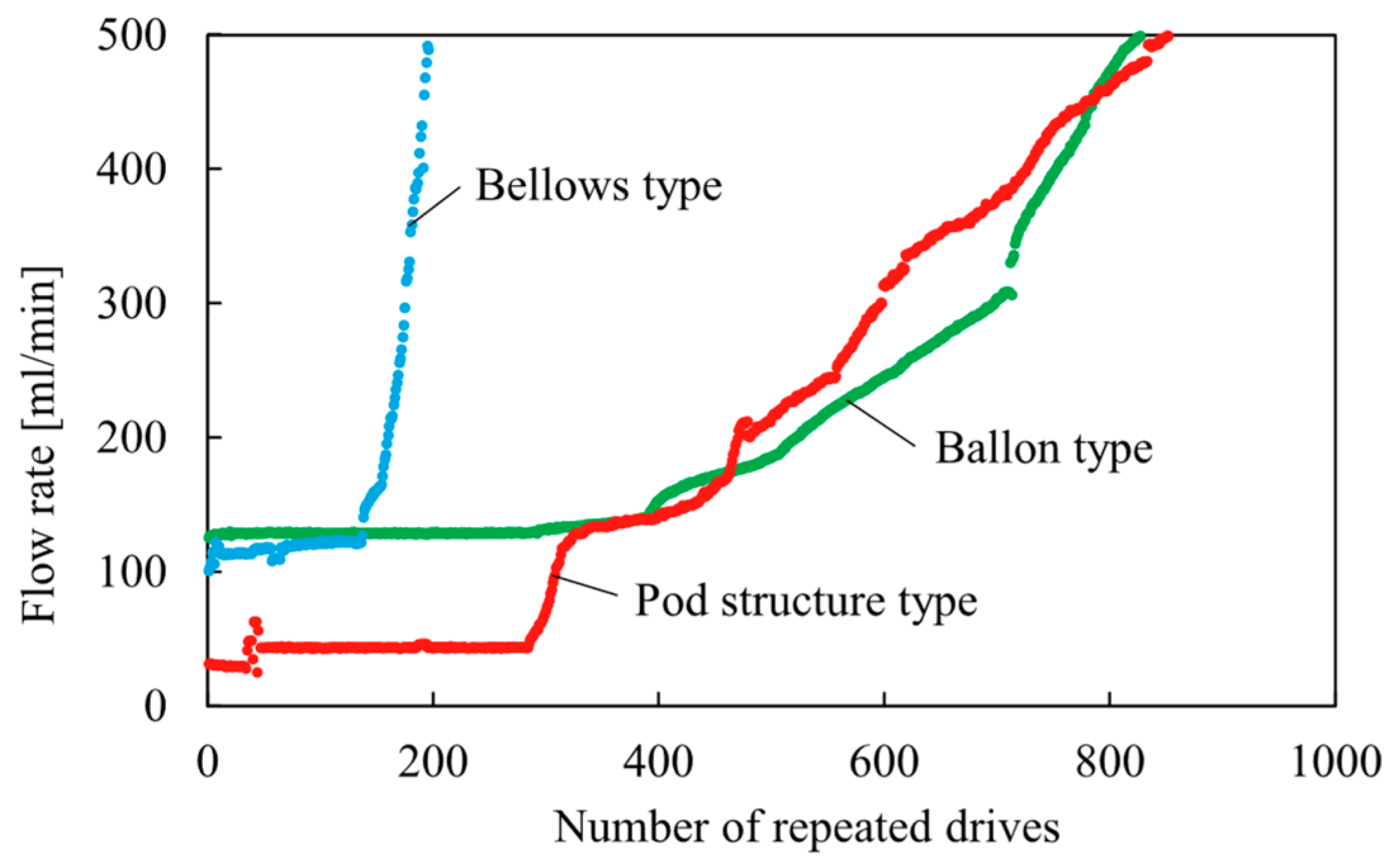
5.2. Repeated Durability

The durability of the two types of actuators was evaluated under repeated deformation. The durability was evaluated by the number of fracture cycles at the maximum deformation in accordance with the relationship between strain amplitude and the number of fracture cycles in general fatigue tests. A cylindrical chamber with no structure was also evaluated in the same manner to check the effect of the structure on durability. The diameter and length of the chamber were 8 mm and 40 mm, respectively. A system configuration diagram of the durability test is shown in Figure 18. A positive pressure of 30 kPa and a negative pressure of −30 kPa were switched by a solenoid valve and the actuator was repeatedly pressurized. The valve was switched after a period of time when the pressure and flow rate stabilized. The failure state was evaluated by measuring the leakage flow rate when a positive pressure was applied. In most cases, the actuator is used by a differential pressure between the positive pressure and open air (0 kPa). However, buckling, which is the cause of failure, does not occur every time under open-air conditions. Therefore, in order to accelerate the fatigue fracture, positive and negative pressures were applied repeatedly as a harder driving condition.
The relationship between the number of repetitive drives of each actuator and the flow rate is shown in Figure 19. The leak in the initial state was confirmed to be at the actuator and joint. This leakage does not affect the characteristics of the actuator, but it cannot be separated because it increases linearly and slightly with the application of pressure.
From this graph, it can be observed that there are areas where the leakage increases rapidly and slowly. In the cylindrical chamber, no rapid increase in leakage was observed. However, the leakage increased slowly with repeated use. Even chambers without a structure showed a tendency to slowly degrade with repeated operation.
The two actuators with a structure showed a rapid increase in leakage with repeated motion. This rapid increase was due to the failure of the structure and the durability in repetitive operation was reduced by this failure. As a feature of the leakage change, it was confirmed that it occurred rapidly, which is unlike normal degradation. The rapid increase occurred at 136 cycles in the bellows type and at 284 cycles in the pod type. In the case of the pod structure, the rapid increase subsided and gradually increased, which is similar to the deterioration of the cylindrical chamber. Thus, it can be assumed that the failure of the structure stopped and did not progress in the pod structure. From the above, it was confirmed that the pod structure improved the durability compared to the conventional bellows type.

6. Conclusions

In this paper, we proposed a new pod structure, which has an equivalent performance to that of the bellows actuator, without folding a non-stretch film. In addition, a method of molding a pod structure on a polyimide film was established and a PI film pneumatic actuator was fabricated. Two types of actuators with the same curvature ratios, a bellows actuator, and a pod actuator were fabricated and evaluated. Both actuators have similar output characteristics and a bending actuator with a pod structure has been successfully realized. By evaluating the repetition durability, we confirmed that the pod structure has approximately twice the repetition durability than that of the bellows structure. The pod structure, which does not have a folded structure and does not have an unfolded part, is useful for improving the durability.
As a result, we have succeeded in fabricating an actuator that can perform arbitrary bending motions with improved durability by molding non-stretchable film. Conventional chambers with no structure have high durability, but their motion is limited to expansion and contraction. Therefore, a different mechanism is required to convert the motion. The pod structure is different from the bellows structure in that the curvature ratio can be easily changed. Therefore, it is possible to fabricate pneumatic actuators made of films with greater design flexibility. By using the molding process proposed in this paper, it will be possible to fabricate actuators with both high durability and complex motion.

Author Contributions

Conceptualization, D.Y. and T.H.; methodology, D.Y., T.H., M.T. and T.M.; software, T.H. and Y.I.; investigation, T.H. and Y.I.; data curation, D.Y. and T.H.; writing—original draft preparation, D.Y.; writing—review and editing, D.Y.; visualization, D.Y. and T.H.; supervision, D.Y., M.T. and T.M.; project administration, D.Y.; funding acquisition, D.Y. All authors have read and agreed to the published version of the manuscript.

Funding

This research was funded by the Fluid Power Technology Promotion Foundation and JSPS KAKENHI Grant Number 15K20908.

Conflicts of Interest

The authors declare no conflict of interest.

References

  1. Schmitt, F.; Piccin, O.; Barbé, L.; Bayle, B. Soft Robots Manufacturing: A Review. Front. Robot. AI 2018, 31, 84. [Google Scholar] [CrossRef] [Green Version]
  2. Walker, J.; Zidek, T.; Harbel, C.; Yoon, S.; Strickland, F.S.; Kumar, S.; Shin, M. Soft Robotics: A Review of Recent Developments of Pneumatic Soft Actuators. Actuators 2020, 9, 3. [Google Scholar] [CrossRef] [Green Version]
  3. Zhao, H.; Li, Y.; Elsamadisi, A.; Shepherd, R. Scalable Manufacturing of High Force Wearable Soft Actuators. Extrem. Mech. Lett. 2015, 3, 89–104. [Google Scholar] [CrossRef]
  4. Schaffner, M.; Faber, J.A.; Pianegonda, L.; Rühs, P.A.; Coulter, F.; Studart, A.R. 3D printing of Robotic Soft Actuators with Programmable Bioinspired Architectures. Nat. Commun. 2018, 9, 878. [Google Scholar] [CrossRef] [PubMed]
  5. Suzumori, K.; Iikura, S.; Tanaka, H. Development of Flexible Microactuator and Its Applications to Robotic Mechanisms. In Proceedings of the 1991 IEEE International Conference on Robotics and Automation, Sacramento, CA, USA, 9–11 April 1991. [Google Scholar]
  6. Sasaki, D.; Noritsugu, T.; Takaiwa, M. Development of High Contractile Pneumatic Artificial Rubber Muscle for Power Assist Device. J. Robot. Mechatron. 2012, 24, 150–157. [Google Scholar] [CrossRef]
  7. Furukawa, S.; Wakimoto, S.; Kanda, T.; Hagihara, H. A Soft Master-Slave Robot Mimicking Octopus Arm Structure Using Thin Artificial Muscles and Wire Encoders. Actuators 2019, 8, 40. [Google Scholar] [CrossRef] [Green Version]
  8. Jones, B.; McMahan, W.; Walker, I. Design and Analysis of a Novel Pneumatic Manipulator. Int. Fed. Acc. Mechatron. Syst. 2004, 37, 687–692. [Google Scholar] [CrossRef]
  9. Hughe, J.; Culha, U.; Giardina, F.; Guenther, F.; Rosendo, A.; Iida, F. Soft Manipulators and Grippers: A Review. Front. Robot. AI 2016, 3, 69. [Google Scholar] [CrossRef] [Green Version]
  10. Elmoughni, H.M.; Yilmaz, A.F.; Ozlem, K.; Khalilbayli, F.; Cappello, L.; Atalay, A.T.; Ince, G.; Atalay, O. Machine-Knitted Seamless Pneumatic Actuators for Soft Robotics: Design, Fabrication, and Characterization. Actuators 2021, 10, 94. [Google Scholar] [CrossRef]
  11. Sasaki, D.; Noritsugu, T.; Takaiwa, M. Development of Pneumatic Soft Robot Hand for Human Friendly Robot. J. Robot. Mechatron. 2003, 15, 164–171. [Google Scholar] [CrossRef]
  12. Wanga, B.; McDaida, A.; Biglari-Abharib, M.; Giffneya, T.; Aw, K. A Bimorph Pneumatic Bending Actuator by Control of Fiber Braiding Angle. Sens. Actuators A Phys. 2017, 257, 173–184. [Google Scholar] [CrossRef]
  13. Hu, H.; Mutlu, R.; Li, W.; Alici, G. A Structural Optimisation Method for a Soft Pneumatic Actuator. Robotics 2018, 7, 24. [Google Scholar] [CrossRef] [Green Version]
  14. Nakamura, T.; Shinohara, H. Position and Force Control Based on Mathematical Models of Pneumatic Artificial Muscles Reinforced by Straight Glass Fibers. In Proceedings of the 2007 IEEE International Conference on Robotics and Automation, Roma, Italy, 10–14 April 2007. [Google Scholar]
  15. Kawamura, S.; Sudani, M.; Deng, M.; Noge, Y.; Wakimoto, S. Modeling and System Integration for a Thin Pneumatic Rubber 3-DOF Actuator. Actuators 2019, 8, 32. [Google Scholar] [CrossRef] [Green Version]
  16. Shapiro, Y.; Wolf, A.; Gabor, K. Bi-bellows: Pneumatic Bending Actuator. Sens. Actuators A Phys. 2011, 167, 484–494. [Google Scholar] [CrossRef]
  17. Sudani, M.; Deng, M.; Wakimoto, S. Modelling and Operator-Based Nonlinear Control for a Miniature Pneumatic Bending Rubber Actuator Considering Bellows. Actuators 2018, 7, 26. [Google Scholar] [CrossRef] [Green Version]
  18. Wakimoto, S.; Suzumori, K.; Ogura, K. Miniature Pneumatic Curling Rubber Actuator Generating Bidirectional Motion with One Air-supply Tube. Adv. Robot. 2011, 25, 1311–1330. [Google Scholar] [CrossRef] [Green Version]
  19. Daerden, F.; Lefeber, D. Pneumatic Artificial Muscles: Actuators for Robotics and Automation. Eur. J. Mech. Environ. Eng. 2000, 47, 10–21. [Google Scholar]
  20. Kurumaya, S.; Nabae, H.; Endo, G.; Suzumori, K. Design of Thin McKibben Muscle and Multifilament Structure. Sens. Actuators A Phys. 2017, 261, 66–74. [Google Scholar] [CrossRef]
  21. Kumar, V.; Ko, U.H.; Zhou, Y.; Hoque, J.; Arya, G.; Varghese, S. Microengineered Materials with Self-Healing Features for Soft Robotics. Adv. Intell. Syst. 2021, 3, 2100005. [Google Scholar] [CrossRef]
  22. Choi, J.; Lee, S.; Kim, J.; Lee, M.; Kim, K.; In, H. Development of a pneumatically-driven Growing Sling to assist patient transfer. In Proceedings of the 2020 IEEE/RSJ International Conference on Intelligent Robots and Systems (IROS), Las Vegas, NV, USA, 25–29 October 2020. [Google Scholar]
  23. Troise, M.; Gaidano, M.; Palmieri, P.; Mauro, S. Preliminary Analysis of a Lightweight and Deployable Soft Robot for Space Applications. Appl. Sci. 2021, 11, 2558. [Google Scholar] [CrossRef]
  24. Takahashi, I.; Fujita, K. Deformation Mechanism Formulation of Differential-Stiffness-Films-Laminated Pouch Motor. In Proceedings of the 2020 IEEE/SICE International Symposium on System Integration (SII), Honolulu, HI, USA, 12–15 January 2020. [Google Scholar]
  25. Jung, J.C.; Jang, J.H.; Rodrigue, H. Inflatable L-shaped Prisms as Soft Actuators for Soft Exogloves. Eng. Res. Express 2019, 1, 025009. [Google Scholar] [CrossRef]
  26. Jung, J.C.; Rodrigue, H. Film-based Anisotropic Balloon Inflatable Bending Actuator. J. Mech. Sci. Technol. 2019, 33, 4469–4476. [Google Scholar] [CrossRef]
  27. Niiyama, R.; Sun, X.; Sung, C.; An, B.; Rus, D.; Kim, S. Pouch Motors: Printable Soft Actuators Integrated with Computational Design. Soft Robot. 2015, 2, 59–70. [Google Scholar] [CrossRef]
  28. Sato, T.; Saito, N.; Ogasawara, T.; Sato, T. Development of Rubberless Artificial Muscle and Fundamental Characteristics. In Proceedings of the 37th Annual Conference of the IEEE IES, Melbourne, VIC, Australia, 7–10 November 2011. [Google Scholar]
  29. Maruyama, D.; Kimura, H.; Koseki, M.; Inou, N. Driving Force and Structural Strength Evaluation of a Flexible Mechanical System with a Hydrostatic Skeleton. J. Zhejiang Univ. Sci. A 2010, 11, 255–262. [Google Scholar] [CrossRef]
  30. Sun, X.; Felton, S.M.; Niiyama, R.; Wood, R.J.; Kim, S. Self-folding and Self-actuating Robots: A Pneumatic Approach. In Proceedings of the 2015 IEEE International Conference on Robotics and Automation, Seattle, WA, USA, 26–30 May 2015. [Google Scholar]
  31. Nishioka, Y.; Uesu, M.; Tsuboi, H.; Kawamura, S.; Masuda, W.; Yasuda, T.; Yamano, M. Development of a Pneumatic Soft Actuator with Pleated Inflatable Structures. Adv. Robot. 2017, 31, 753–762. [Google Scholar] [CrossRef]
  32. Yamaguchi, D.; Hanaki, T.; Ishino, Y.; Hara, M.; Takasaki, M.; Mizuno, T. Concept and Prototype of Soft Actuator for Liquid Nitrogen Temperature Environments. J. Robot. Mechatron. 2020, 32, 1019–1026. [Google Scholar] [CrossRef]
  33. Hanaki, T.; Yamaguchi, D.; Ishino, Y.; Hara, M.; Takasaki, M.; Mizuno, T. Evaluation of Leakage Caused by Bending Cycle of Soft Film Actuator for Ultra-low Temperature. In Proceedings of the Conference on JSPE 2016 Autumn, Ibaraki, Japan, 6–8 September 2016. (In Japanese). [Google Scholar]
Figure 1. Schematic view of pneumatic bellows actuator of PI films: (a) folded actuator; (b) unfolded actuator by applying gas pressure.
Actuators 10 00177 g001
Figure 2. Shape of pod structure.
Actuators 10 00177 g002
Figure 3. Required elongation of upper film.
Actuators 10 00177 g003
Figure 4. Side section view of the bellows structure.
Actuators 10 00177 g004
Figure 5. Cross-section of the curved state (ring cut direction).
Actuators 10 00177 g005
Figure 6. Development view of the molded shape.
Actuators 10 00177 g006
Figure 7. Three-dimensional drawing and photograph of duralumin mold for PI film molding: (a) 3D model of mold; (b) photograph of fabricated mold.
Actuators 10 00177 g007
Figure 8. Outline of molding process.
Actuators 10 00177 g008
Figure 9. Molding machine for PI film.
Actuators 10 00177 g009
Figure 10. Photograph of molded pod structure on PI film and measured elongated width: (a) photograph from front; (b) photograph from above; (c) schematic diagram of molded shape from above.
Actuators 10 00177 g010
Figure 11. Relationship between the molded width, temperature, and applied pressure.
Actuators 10 00177 g011
Figure 12. Fabrication method of bellows structure; (a) folding films; (b) bending upper film for welding; (c) welding of three sides.
Actuators 10 00177 g012
Figure 13. Two films for the fabrication of pod structure.
Actuators 10 00177 g013
Figure 14. Fabricated actuators: (a) photograph of pod structure actuator; (b) photograph of bellows structure actuator.
Actuators 10 00177 g014
Figure 15. Bending deformation of the pod structure actuator.
Actuators 10 00177 g015
Figure 16. Measuring setup of torque and pressure evaluation.
Actuators 10 00177 g016
Figure 17. Relationship between pressure and generated torque of the two types of actuators.
Actuators 10 00177 g017
Figure 18. System configuration diagram of the repeated durability test.
Actuators 10 00177 g018
Figure 19. Relationship between the number of repetitive drives of each actuator and the flow rate.
Actuators 10 00177 g019
Table 1. Design parameter for pod structure.
PropertiesSymbolValue
Width of upper film w U 20 mm
Width of lower film w L 10 mm
Standard molding widthb3 mm
Curvature ratioλ3
Publisher’s Note: MDPI stays neutral with regard to jurisdictional claims in published maps and institutional affiliations.

