Abstract
A piston piezoelectric (PZT) pump has many advantages for the use of light actuators. How to deal with the contradiction between the intermittent oil supplying and position control precision is essential when designing the controller. In order to accurately control the output of the actuator, a backstepping sliding-mode control method based on the Lyapunov function is introduced, and the controller is designed on the basis of establishing the mathematical model of the system. The simulation results show that, compared with fuzzy PID and ordinary sliding-mode control, backstepping sliding-mode control has a stronger anti-jamming ability and tracking performance, and improves the control accuracy and stability of the piezoelectric pump-controlled actuator system.
1. Introduction
Micro and miniature hydraulic pumps powered by smart structures are becoming an immerging technology in light actuators [1,2,3], wherein a piezoelectric (PZT) pump is an instance. Compared with a traditional motor-driven pump, the PZT pump has an advantageous structure, low weight, high efficiency, low noise, high reliability and so on [4,5]. In some situations which have harsh requirements on power-to-weight ratio and noise, such as aerospace and movable robotics, a piezoelectric pump-controlled actuator is an alternative to a light, reliable actuation scheme [6,7]. As for a pump in a hydraulic actuator, fine delivery properties are of great concern [8]. Smooth and steady oil feeding to a hydraulic cylinder is the common requirement. Both piston and gear pumps can give rise to inherent flow ripple, which easily induces actuator creeping or buffeting. Moreover, ferroelectric hysteresis of the PZT material and leakage in the pump are the factors influencing the oil delivery performance. To severely restrict volume and weight of an airborne actuator, the piston number of a PZT pump should be arranged as low as possible. However, the less the piston number is, the worse the flow delivery property of the pump is. Therefore, it is crucial to find a balance between them at the same time, as the PZT pump is particularly prone to strong nonlinearity, affecting motion control performance of the actuator using the pump.
Sliding-mode control (SMC) is a conventional variable structure robust control method [9]. By selecting the appropriate sliding-mode surface and reaching a balance, good tracking performance and anti-jamming ability of the system can be guaranteed [10,11]. SMC is extensively adopted in aerospace, medicine and other applications [12,13,14,15]. For the fuel quantity actuator system, there exist nonlinear and multi-source disturbances. A continuous sliding-mode control based on a multi-source disturbance observer is proposed, which can effectively depress the steady-state fluctuation [16]. A SMC volume control scheme for a servo pump-hydraulic cylinder system is discussed, which constitutes a pump-controlled servo motor for a steam control valve [17]. Aiming at an electric fuel pump system for a more electric aero-engine, a linear quadratic integral sliding surface is adopted, which improves the robustness of the system [18]. A nonlinear sliding-mode controller is applied to the force tracking of a PZT hydraulic pump-driven system [19]. Similarly, a self-tuning fuzzy sliding-mode compensation-adaptive fuzzy controller is introduced for force control by a variable speed pump control system. Experimental results show that the proposed control method allows good control performance and robustness to parameter changes and external disturbances [20,21]. In order to improve the liquid level control performance of a two-axis pump-controlled folding machine, a coupled adaptive self-organizing sliding-mode fuzzy controller is constructed [22]. An output-based digital integral terminal sliding-mode predictive control scheme is designed, which is especially suitable for precise motion control of a piezoelectrically-actuated positioning system [23]. In the presence of unknown disturbances and model uncertainties, a nonlinear backstepping sliding-mode controller (BSMC) incorporated with a disturbance observer is fabricated for stratospheric airship trajectory tracking [24]. A two-degree-of-freedom piezoelectric micro-operating system with a robust backstepping sliding-mode controller also exhibits satisfying performance, especially in chattering elimination [25].
Different from a traditional hydraulic pump driven by an electric motor, the piezoelectric piston pump with a hydraulic amplifier has the advantages of fast response, large output, and excellent anti-electromagnetic interference. An electro-hydrostatic actuator with a piezoelectric pump as the power and control element is presented as an alternative solution to light actuation. The structure and working principle of the piezoelectric pump are introduced, and the pump-controlled hydraulic cylinder system is mathematically modeled and simulated. A backstepping sliding-mode control based on the Lyapunov function is proposed and the controller is designed on the basis of the mathematical model of the system. In order to improve the problem that conventional sliding-mode control easily gives rise to the system chattering, the backstepping sliding-mode control utilizes the saturation function to optimize the controller. The control method proposed in this paper provides an effective solution to good input tracking of the piezoelectric pump-driven actuator. This paper has the following structure: Section 2.1 is about the principle and configuration of the pump. Then, the mathematical model is described in Section 2.2. Section 2.3 details the backstepping sliding-mode control design and Section 3 is about the results. Finally, Section 4 outlines the conclusions.
2. Principle and Methods
2.1. Principle and Configuration
In Figure 1a, the electro-hydrostatic actuator comprises a piezoelectric pump, a hydraulic cylinder with a displacement transducer and a directional valve. Figure 1b shows the schematic diagram of the piezoelectric pump. The hydraulic displacement amplifier consists of two pistons with different diameters and the fluid enclosed by the two pistons and the housing. When the piezoelectric stack moves the large piston the squeezed fluid inside builds up enough pressure to push the small piston with amplified displacement. The hydraulic displacement amplifier adopted in the pump can magnify the stack stroke dozens of times, which allows the pump to deliver an average flow much more than that without the amplifier. The opening and closing of the suction valve and the discharge valve depend on the pressure difference across the valve plates, which is called a passive flow distribution process. When a sinusoidal voltage is applied, the piezoelectric stack moves the large piston in sinusoidal mode [26]. With the action by the amplifier, the small piston transmits the amplified displacement to the piston of the pump cavity. During the reciprocating motion following the piezoelectric stack, changing pressure in the pump cavity makes the suction and discharge valve open or close alternately in a pumping cycle. The delivery flow rate of the pump can be adjusted by changing the voltage amplitude and frequency applied to the PZT stack, which achieves the speed modulation of the cylinder.
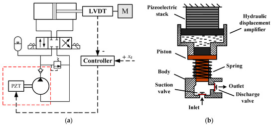
Figure 1.
System principle and design: (a) Principle of the actuator; (b) Schematic diagram of the PZT pump.
Flow distribution of the PZT pump involves four stages: compression, discharge, expansion, and intake. The working principle of the single-piston pump determines an intermittent output, which exacerbates the delivery flow of the pump and then induces the jitter of the actuator. The control algorithm proposed in this paper has reference significance in the response buffeting reduction of the actuator.
2.2. Mathematical Model
According to the piezoelectric equation, the strain tensor of piezoelectric material can be obtained as the following:
where is the elastic compliance constant of the piezoelectric material, is the stress tension of the piezoelectric material, is the piezoelectric constant matrix, is the electric field strength applied on the piezoelectric material. Then, the strain characteristics of single-layer piezoelectric ceramics can be obtained.
where the longitudinal thickness of the single piezoelectric ceramic is , the deformation of the single piezoelectric ceramic is , the external force acting on the stack is , the cross-sectional area of the ceramic chip is . The piezoelectric stack is composed of multiple ceramic chips in parallel on the circuit, which means the working voltage on each piezoelectric ceramic is the same. Assuming that the number of piezoelectric stacks is and the voltage applied on the ceramic chip is , the total elongation of the stack is computed as:
The fluid continuity equation of the pump cavity can be obtained by defining elastic bulk modulus.
where and are the inlet and outlet flow rate of the pump, respectively. is the piston diameter, and is the piston displacement of the pump chamber. Dynamic equations of two distributing valves are expressed as:
where and are the inlet pressure and outlet pressure of the pump, respectively. and are the port diameters of suction and discharge valves, respectively. and are the stiffness of the tightening springs for the suction and discharge valves, respectively. and are the openings of the valves, respectively. and are the pre-compression amounts of the springs, respectively. and are the mass of the corresponding valve plates, respectively. Flow continuity equations for two valves are:
where is the flow coefficient of the valves, and is the fluid density. The deformation of the valve plates in the opening and closing process is very small. Accordingly, in order to simplify the calculation, the motion assembly of the valve is assumed as a rigid body. The motion of the valve plate satisfies the following equation:
where is the fluid force on the plate; is the spring force on the plate; is the initial force; is the spring stiffness; is the displacement of the valve plate; is the acceleration of the valve plate at any time and is the mass of the valve plate. The output displacement, speed and load pressure of the hydraulic cylinder are defined as state variables, and the state space equation of the system can be obtained:
where is the output displacement; is the load pressure; is the damping coefficient of the hydraulic cylinder; and are the equivalent mass and effective cross-sectional area, respectively. and are the friction and external load, respectively. is the initial volume of the hydraulic cylinder; is the piston cross-sectional area of the pump chamber; is the driving frequency and is the proportional relationship between the amplitude of piezoelectric output voltage and the piston displacement of the pump chamber. is the elastic bulk modulus of oil. The hydraulic magnification ratio is linearized without considering the effect of piezoelectric hysteresis.
2.3. Backstepping Sliding-Mode Control Design
The basic idea of the backstepping control method is to decompose the complex nonlinear system into subsystems that do not exceed the system order, and then design Lyapunov functions and intermediate virtual control variables for each subsystem, push the subsystem back to the whole system, and integrate them to complete the design of the whole control law. However, the separate backstepping control needs accurate modeling information of the controlled object, and it is not robust to the disturbance of the model. A backstepping method can effectively compensate for the unmatched interference in the system, but it relies on the accurate mathematical model of the system. By contrast, the sliding-mode control is insensitive to the accuracy of the mathematical model, and can completely eliminate the influence of matching interference on the system. although it is difficult to deal with the mismatched interference.
By introducing the sliding-mode term into the backstepping method, the design conflict between accurate model and mismatched interference can be solved by combining the two characteristics. The following is the design process of the backstepping sliding-mode controller.
Applying the backstepping control to make the output of the system track the given , suppose is a third-order variable. Defining tracking error as a reference signal:
In the subsystem, derive the Lyapunov function:
In order to make less than 0, take the virtual control of as:
where is the coefficient. The subsystem is defined as follows:
In subsystem, derive the Lyapunov function:
where . In order to make , take the virtual control of as:
where is the coefficient. subsystem is defined as follows:
subsystem yields the Lyapunov function:
In order to make , take the virtual control of as:
In order to weaken the effect of buffeting, the is used to replace the symbolic function in the ideal sliding-mode:
where is the boundary layer. Outside the layer, switching control is adopted; inside the boundary layer, linearized feedback control is adopted.
So far, the design of the sliding-mode backstepping controller and the theoretical proof of the convergence of the tracking error have been completed. The block diagram of the control system is shown in Figure 2. The green line stands for a state control signal to switch the flow direction of the pump. The directional valve is a two-position two-way valve. The deviation signal e is the input to the valve, with a positive or negative value, changing the flow direction to and from the cylinder chamber, which switches the motion direction of the cylinder. In experiments, the input signal of the directional valve can be obtained by amplifying and rounding the error signal based on algorithms.
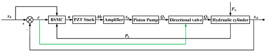
Figure 2.
Block diagram of the backstepping sliding-mode control system.
3. Results
Due to good practicability, fuzzy PID control has been widely used in engineering. Based on the fuzzy PID method, common sliding-mode control strategy and backstepping sliding-mode control strategy, the output characteristics of the piezoelectric piston pump controlled hydraulic cylinder system under constant load and random load are analyzed. By adjusting the appropriate controller parameters, the response of the hydraulic cylinder under the three control strategies reaches a better level. The simulation results are as follows. Table 1 shows the main simulation parameters.

Table 1.
Model parameters of the simulation.
Figure 3 shows the comparison of the input voltage of the piezoelectric stack under fuzzy PID and backstepping sliding-mode control. The output of the fuzzy PID controller varies sinusoidally with the instruction signal, and the maximum amplitude is less than the rated voltage of the piezoelectric stack. The output of the backstepping sliding-mode controller is similar to the dense square wave signal and oscillates in the range of 0–1000 V.
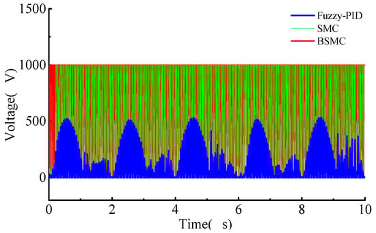
Figure 3.
Input voltage of the piezoelectric stack.
Figure 4 shows the variation law of the pump outlet flow rate with time under the sinusoidal displacement instruction, and the difference between the two control strategies can be seen from the instantaneous flow rate change law. Under the fuzzy PID control, the outlet flow fluctuates in a wide range due to the sinusoidal variation of the controller input voltage amplitude. Furthermore, the sinusoidal motion of the pump cavity piston driven by the stack leads to flow instability and large pulsation rate, which are the main reason for the large tracking error of the hydraulic cylinder. Moreover, the overall trend of flow amplitude is sinusoidal, and the maximum instantaneous flow reaches 1.5 L/min and there exists a reflux phenomenon. Under the common sliding-mode control, the outlet flow fluctuation of the pump is very small, and the flow pulsation rate is even smaller. Under the sliding-mode control, the input of the controller is a sinusoidal voltage with little amplitude fluctuation, which leads to a good regularity of the reciprocating motion of the pump cavity piston, so the outlet flow fluctuation is much smaller and the response of the hydraulic cylinder is more stable.
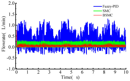
Figure 4.
Outlet flow of the pump under random load.
By applying different amplitudes of load force (100 N, 200 N, 500 N) to the hydraulic cylinder, the variation law of the sinusoidal response of the system is obtained. The sinusoidal instruction signal is set to be mm. As shown in Figure 5, when external load exists in the system, there will be a lag in the response of the hydraulic cylinder under the fuzzy PID control, and this lag becomes more obvious with the increase in the load. When the load reaches 500 N, the output displacement of the hydraulic cylinder under the fuzzy PID control has a serious chattering phenomenon, while the displacement of the hydraulic cylinder under ordinary sliding-mode control and backstepping sliding-mode control has good anti-interference ability. Because of the inherent intermittent fuel supply characteristics of the single-piston piezoelectric pump, and the position control is determined by constantly switching the two-chamber oil path of the hydraulic cylinder, the fuzzy PID control does not have the saturation function of suppressing chattering compared with the backstepping sliding-mode control, so the fuzzy PID control will have greater zero fluctuation in the case of external load disturbance. Under three load conditions, the output displacement oscillation range under the backstepping sliding-mode control is smaller and the stability is higher compared with the ordinary sliding-mode control. The robustness of the backstepping sliding-mode is better than that of the ordinary sliding-mode.
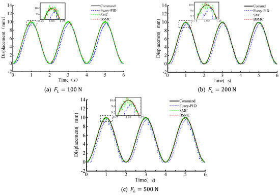
Figure 5.
Sinusoidal response of the cylinder: (a) ; (b) ; (c) .
Figure 6 shows the displacement response of the hydraulic cylinder under the step displacement instruction 10 mm by applying 100 N, 200 N and 500 N load to the system at 5 s, 10 s and 15 s, respectively. It can be seen that under the fuzzy PID control, the displacement of the hydraulic cylinder fluctuates differently at 5 s, 10 s and 15 s. Compared with the previous 5 s no-load condition, applying load force can restrain the steady-state chattering phenomenon of the hydraulic cylinder under fuzzy PID control, but a certain steady-state error appears in the hydraulic cylinder. The greater the load force is, the larger the fluctuation is. Ordinary sliding-mode and backstepping sliding-mode control are not disturbed by random load under sinusoidal displacement instruction. The output displacement under SMC and that under BSMC have chattering both, but the chattering range of BSMC is smaller due to the saturation function optimization to the control strategy.
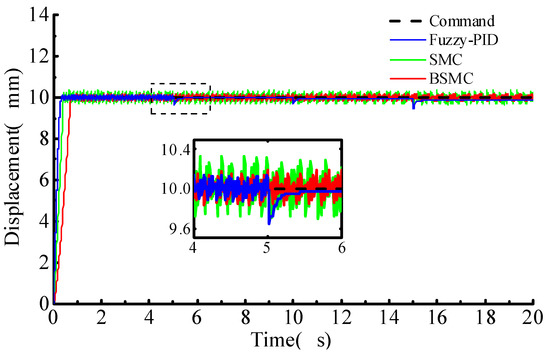
Figure 6.
Step response of the cylinder under random load.
Given sinusoidal instruction displacement, the displacement response of the hydraulic cylinder by applying the random load force is shown in Figure 7, Figure 8 and Figure 9. In the random load range of 0–500 N, the output displacement of the hydraulic cylinder with backstepping sliding-mode control has the best anti-interference ability, the displacement tracking effect is very ideal, and the fuzzy PID has the worst robustness.
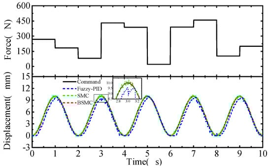
Figure 7.
Sine response of the cylinder under random step load.
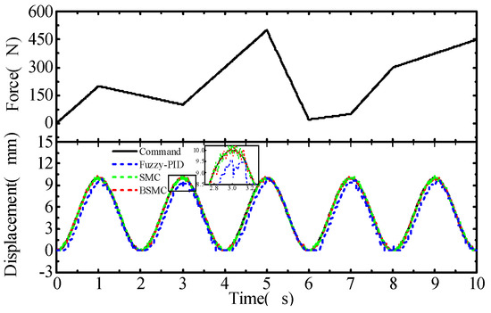
Figure 8.
Sine response of the cylinder under random ramp load.
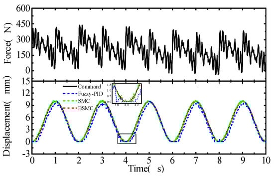
Figure 9.
Sine response of the cylinder under random sinusoidal load.
Figure 10 shows the tracking error of the sinusoidal response of the hydraulic cylinder under random load. The maximum tracking error of the system under fuzzy PID control can reach 1.5 mm and the load fluctuation range is large. The error fluctuation range under backstepping sliding-mode control is small, which indicates the good tracking performance of the hydraulic cylinder.
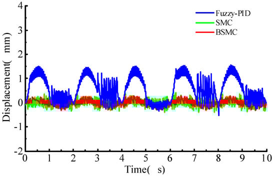
Figure 10.
Tracking error of sinusoidal response of the cylinder under random load.
Figure 11 shows the velocity change of the hydraulic cylinder under sinusoidal instructions with a random load. It can be seen that the fluctuation range of the cylinder speed with conventional sliding-mode control is smaller than that with fuzzy-PID, although both are larger than that with backstepping sliding-mode control. The cylinder speed with the three control algorithms is illustrated in Figure 11. The system adopting the fuzzy PID has the largest fluctuation amplitude of the tracking error, Comparatively, the backstepping sliding-mode control allows the system with the lowest fluctuation amplitude of the tracking error.
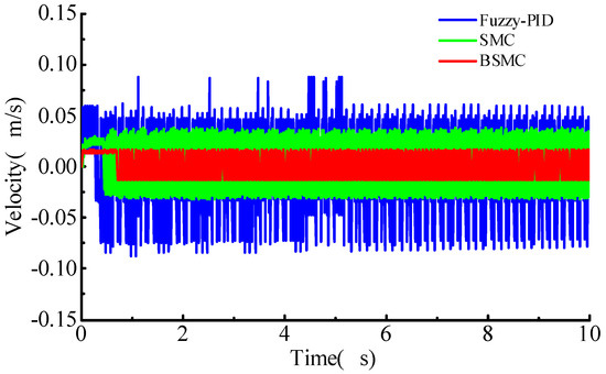
Figure 11.
Cylinder speed for sinusoidal command.
4. Conclusions
In this paper, the hydraulic cylinder position control system driven by a PZT piston pump is built, and BSMC is designed to realize the servo control of the hydraulic cylinder output displacement. Comparing the output characteristics of the actuator under BSMC, SMC and Fuzzy PID, the main conclusions are as follows:
When no external load disturbance is applied to the system, the fuzzy PID control has a certain advantage in response time. When there is external load disturbance in the system, the hydraulic cylinder under the fuzzy PID control has response lag and large steady-state error. Especially in the simulated sinusoidal response of the cylinder exerted by a random load, the maximum tracking error of the system adopting fuzzy PID control is up to 1.5 mm, several times that of the BSMC proposed in this paper. Ordinary sliding-mode control and backstepping sliding-mode control have better anti-interference ability than the fuzzy PID. Compared with SMC, BSMC shows better stability and robustness. For the hydraulic cylinder system, the tracking performance of the system response of BSMC is better than that of SMC and fuzzy PID control, and has the stronger anti-interference ability and better robustness. BSMC based on weakening the chattering phenomenon of a pump-controlled hydraulic cylinder combines the advantages of the sliding-mode control and the backstepping control and shows a better control effect.
Author Contributions
Writing—original draft, B.W.; Methodology, B.W.; Modeling, P.R.; Simulation, P.R.; Writing—review and editing, P.R.; Control algorithm, X.H.; References, X.H.; English Editing, X.H. All authors have read and agreed to the published version of the manuscript.
Funding
This research was funded by the Natural Science Foundation of Jiangsu Province, grant number BK20171412.
Conflicts of Interest
The authors declare no conflict of interest.
References
- Larson, J.P.; Farinholt, K.M.; Griffin, S.F.; Dapino, M. High-Frequency valve development for smart material electro-hydraulic actuators. Proc. SPIE 2011, 7979, 843–845. [Google Scholar]
- Zhao, Y.P.; Chen, D.F.; Lu, Q.G. The Development and Application of Smart Material Pumps. Adv. Mater. Res. 2013, 681, 260–265. [Google Scholar] [CrossRef]
- Xu, B.; Shen, J.; Liu, S.; Su, Q.; Zhang, J. Research and Development of Electro-hydraulic Control Valves Oriented to Industry 4.0: A Review. Chin. J. Mech. Eng. 2020, 33, 29. [Google Scholar] [CrossRef] [Green Version]
- Zhang, J.-H.; Wang, Y.; Huang, J. Advances in Valveless Piezoelectric Pump with Cone-shaped Tubes. Chin. J. Mech. Eng. 2017, 30, 766–781. [Google Scholar] [CrossRef]
- Dong, J.S.; Liu, R.G.; Liu, W.S.; Chen, Q.Q.; Yang, Y.; Wu, Y.; Yang, Z.G.; Lin, B.S. Design of a piezoelectric pump with dual vibrators. Sens. Actuators A Phys. 2017, 257, 165–172. [Google Scholar] [CrossRef]
- Sun, M.; Ouyang, X.; Mattila, J.; Yang, H.; Hou, G. One Novel Hydraulic Actuating System for the Lower-Body Exoskeleton. Chin. J. Mech. Eng. 2021, 34, 31. [Google Scholar] [CrossRef]
- Escareno, J.A.; Rakotondrabe, M.; Habineza, D. Blackstepping-Based robust-adaptive control of a nonlinear 2-DOF piezoactuator. IFAC Control Eng. Pract. (CEP) 2015, 41, 57–71. [Google Scholar] [CrossRef]
- Grabbel, J.; Monika, I. An investigation of swash plate control concepts for displacement controlled actuators. Int. J. Fluid Power 2005, 6, 19–36. [Google Scholar] [CrossRef]
- Shtessel, Y.; Edwards, C.; Fridman, L.; Levant, A. Sliding Mode Control and Observation; Springer: New York, NY, USA, 2014. [Google Scholar]
- Shtessel, Y.B.; Moreno, J.A.; Fridman, L.M. Twisting sliding mode control with adaptation: Lyapunov design, methodology and application. Automatica 2017, 75, 229–235. [Google Scholar] [CrossRef]
- Han, Y.; Kao, Y.; Gao, C.J.A. Robust sliding mode control for uncertain discrete singular systems with time-varying delays and external disturbances. Automatica 2017, 75, 210–216. [Google Scholar] [CrossRef]
- Sun, H.; Hou, L.; Zong, G.; Yu, X. Fixed-Time Attitude Tracking Control for Spacecraft with Input Quantization. IEEE Trans. Aerosp. Electron. Syst. 2018, 55, 124–134. [Google Scholar] [CrossRef]
- Ginoya, D.; Shendge, P.D.; Phadke, S. Sliding Mode Control for Mismatched Uncertain Systems Using an Extended Disturbance Observer. IEEE Trans. Ind. Electron. 2013, 61, 1983–1992. [Google Scholar] [CrossRef]
- Sunila, M.S.; Sankaranarayanan, V.; Sundereswaran, K. Optimised sliding mode control for MIMO uncertain non-linear system with mismatched disturbances. Electron. Lett. 2018, 54, 290–291. [Google Scholar] [CrossRef]
- Saleh, M. Adaptive Global Terminal Sliding Mode Control Scheme with Improved Dynamic Surface for Uncertain Nonlinear Systems. Int. J. Control Autom. Syst. 2018, 16, 1692–1700. [Google Scholar]
- Wang, X.; Sun, H.; Li, S.; Yang, J. Multi-Source Disturbance Observer Based Continuous Sliding Mode Control for Fuel Quantity Actuator System. In Proceedings of the 2020 Chinese Control and Decision Conference (CCDC), Hefei, China, 21–23 May 2020. [Google Scholar]
- Yan, G.; Jin, Z.; Zhang, T.; Zhao, P. Position Control Study on Pump-Controlled Servomotor for Steam Control Valve. Processes 2021, 9, 221. [Google Scholar] [CrossRef]
- Ding, R.; Xiao, L.; Jin, X. Robust Control for Electric Fuel Pump with Variant Nonlinear Loads Based on a New Combined Sliding Mode Surface. Int. J. Control Autom. Syst. 2019, 17, 716–728. [Google Scholar] [CrossRef]
- Kim, G.W.; Wang, K.W. Switching sliding mode force tracking control of piezoelectric-hydraulic pump-based friction element actuation systems for automotive transmissions. SMART Mater. Struct. 2009, 18, 085004. [Google Scholar] [CrossRef]
- Chiang, M.H.; Lin, H.T. The Force Control of a Novel Variable Rotational Speed Hydraulic Pump-Controlled System Using Adaptive Fuzzy Controller with Self-Tuning Fuzzy Sliding-Mode Compensation. ICFP Proc. Vol. 2009, 44, 968–973. [Google Scholar] [CrossRef] [Green Version]
- Lee, L.W.; Chen, C.C.; Li, I.H.; Huang, J.Y. The positioning control of an electro-hydraulic variable rotational speed pump-controlled system using adaptive fuzzy controller with self-tuning fuzzy sliding mode compensation. In Proceedings of the 2011 IEEE International Conference on Fuzzy Systems (FUZZ-IEEE), Taipei, Taiwan, 27–30 June 2011. [Google Scholar]
- Wong, R.-H. Sliding-Mode Fuzzy Control Using in a Double-Axial Pump-Controlled Folding Machine. In Proceedings of the ICAMAR 2013, Taipei, Taiwan, 13–14 July 2013; Volume 418, pp. 88–91. [Google Scholar]
- Xu, Q. Digital Integral Terminal Sliding Mode Predictive Control of Piezoelectric-Driven Motion System. IEEE Trans. Ind. Electron. 2016, 63, 3976–3984. [Google Scholar] [CrossRef]
- Liu, S.Q.; Whidborne, J.F.; He, L. Backstepping sliding-mode control of stratospheric airships using disturbance-observer. Adv. Space Res. 2020, 67. [Google Scholar] [CrossRef]
- Cheng, C.H.; Hung, S.-K. A Piezoelectric Two-Degree-of-Freedom Nanostepping Motor with Parallel Design. IEEE ASME Trans. Mechatron. 2016, 21, 2197–2199. [Google Scholar] [CrossRef]
- Kim, J.; You, K.; Choe, S.-H.; Choi, H. Wireless Ultrasound Surgical System with Enhanced Power and Amplitude Performances. Sensors 2020, 20, 4165. [Google Scholar] [CrossRef] [PubMed]
Publisher’s Note: MDPI stays neutral with regard to jurisdictional claims in published maps and institutional affiliations. |
© 2021 by the authors. Licensee MDPI, Basel, Switzerland. This article is an open access article distributed under the terms and conditions of the Creative Commons Attribution (CC BY) license (https://creativecommons.org/licenses/by/4.0/).