Abstract
Different from ordinary AC machines, the design of a bearingless permanent magnet slice motor (BPMSM) considers not only the torque performance, but also the passive and active suspension properties. In addition, BPMSM for a maglev centrifugal pump has unique design characteristics due to the integration of the pump head and sensors. This paper investigates evaluation and design techniques based on a cluster of performance metrics targeting on developing BPMSM for a maglev centrifugal pump. The cluster of performance metrics for BPMSM, including passive stiffness (, , , , and ) and active factors ( and ), is first proposed and an evaluation function is constructed. Then, practical configurations of BPMSM for a maglev centrifugal pump are summarized. Based on the cluster of performance metrics, the finite-element method (FEM) is used to explore the impact of the rotor magnetization (sinusoidal, diametric, and radial method) on motor properties. Subsequently, the complete design process of BPMSM for a maglev centrifugal pump is introduced and key differences (including three crucial geometric parameters: ratio of rotor height to diameter , magnetic gap length , and stator tooth width ) in the design considerations between BPMSM and general bearingless motors are analyzed. Finally, the upgraded performance (, , , , , and increased by about 29%, 38%, 33%, 31%, 21%, and 15%, respectively) of the designed candidate is obtained, which verifies the effectiveness of the proposed design methods.
Bearingless permanent magnet slice motors (BPMSM) are electric motors with integrated magnetic bearing. The functions of the motor and magnetic bearing are combined into a single iron circuit, enabling a compact design. The permanent magnet rotor is disc-shaped, ensuring passive stability in three degrees of freedom, thus simplifying bearing control schemes. The rotor is suspended by a magnetic field, enabling its non-contact suspension and encapsulation. Therefore, BPMSM is particularly suitable for applications in maglev centrifugal, pumps which have been successfully employed in medical, semiconductor, chemical, and other industries [1,2,3].
To the authors’ knowledge, current literature on BPMSM primarily focuses on topology [4,5,6,7,8], control [9,10,11,12,13,14], and sensing [15,16,17]. The design of BPMSM has received only limited research attention. A detailed study of configuration and rotor topology was presented in the early literature [18,19,20]. In another research study, a comparison between separated and combined winding concepts was investigated in detail [21]. Additionally, in one of Dr. Zhu’s research studies [22], short-pitch windings and a type of cosine shape of permanent magnets were adopted for BPMSM to inhibit higher harmonics. Furthermore, Sun et al. introduced an interior composite-rotor type BPMSM [23]. Despite these contributive research studies, there is still no complete guideline for BPMSM design.
Currently, the design of initial parameters for bearingless motors still relies on the design process of traditional AC motors [24]. The classic design procedure of ordinary AC machines just follows analytic equations governing the torque performance but does not consider design demands of the suspension performance. Although it has a small contribution to the acquisition of initial parameters for bearingless motors of certain topologies [25,26], the design concerning all the initial dimensions of BPMSM cannot be completed only through the classic motor design process, such as the ratio of rotor height to diameter. In addition, the initial parameters obtained by the design process that only considers torque performance are usually not good enough in terms of suspension performance; thus, it still requires a lot of time for iterative design. Therefore, a comprehensive cluster of performance metrics (including passive and active properties) and the corresponding evaluation method are required to design initial parameters for BPMSM. Since the 3-D electromagnetic finite-element method (FEM) has acceptable accuracy [26], it is used as a calculation tool for performance metrics in this research.
This paper considers a BPMSM for the application of maglev centrifugal pumps with the small and medium flow (20–300 L/min) as the target. The rotor of BPMSM for a maglev centrifugal pump suffers from more disturbance caused by the fluid in the pump compared to ordinary bearingless motors [27]. Consequently, when designing BPMSM for a maglev centrifugal pump, the suspension stability is given higher priority. Additionally, the design of BPMSM for a maglev centrifugal pump has the following particularities:
- (1)
- Three degrees of freedom of the rotor are passively stable, i.e., it cannot be compensated by active control. Thus, the ratio of rotor height to diameter should be designed to ensure high passive suspension stiffness.
- (2)
- The magnetic gap cannot be reduced arbitrarily, since the encapsulation of the rotor and pump casing has a minimal thickness for mechanical strength requirements.
- (3)
- The design of stator tooth width should consider the installation space for radial position sensors, such as eddy current sensors.
The combination of these items leads to the special geometric design and parametric analysis of BPMSM for a maglev centrifugal pump.
The primary goal of this paper is to provide a cluster of performance metrics together with evaluation and design techniques for the development and research of BPMSM for a maglev centrifugal pump. The paper first introduces the cluster of performance metrics and evaluation methods for active and passive performance of BPMSM in Section 2. In Section 3, based on the cluster of performance metrics, practical motor configurations are summarized and three rotor magnetization methods of BPMSM are compared through FEM. Subsequently, Section 4 presents the complete design process of BPMSM for a maglev centrifugal pump and the design analysis of three key specialized geometric dimensions for BPMSM. Finally, the better performance of the designed candidate is presented to prove the effectiveness of the design techniques.
1. Performance Metric Cluster
1.1. Passive Properties
For bearingless slice motors, since the rotor diameter is larger than its height, the three spatial degrees of freedom of the diametrically magnetized rotor (translation along the z-axis and tilting around the x- and y-axis) are passively stabilized [28]. As illustrated in Figure 1a, the reluctance forces to counteract the displacement are generated if the rotor is deflected in the axial direction or tilted. To characterize the passive properties, each degree of freedom is assigned a corresponding stiffness around the equilibrium position as follows:
where and represent the forces in the direction i and the torque around the axis i, respectively. Each passive stiffness can be regarded as a constant under the working conditions and obtained by linear fitting in the following research. Degrees of freedom, in which passive bearing stiffness is positive, have a stabilizing effect. Note that and are negative in BPMSM, causing the radial instability in the open-loop.
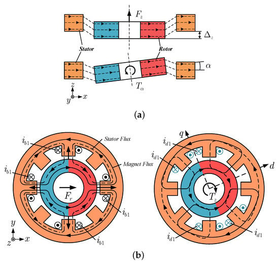
Figure 1.
(a) A stabilizing axial reluctance force and restoring torque caused by a rotor deflection in the z-axis direction and tilting around the axis perpendicular to the direction of magnetization, respectively. (b) Active suspension force and torque generation.
1.2. Active Force and Torque
Based on a Maxwell stress tensor, the stress on the surface of any object can be calculated as follows [20]:
where is the normal component of the flux density in the air gap, and is the current density distribution on the stator surface. The force or torque acting on the rotor of BPMSM is determined by the surface integral:
where h and R represent the height and radius of the rotor, respectively. denotes the circumferential variable in cylinder coordinates.
The two aforementioned cases of active suspension force and torque generation are depicted in Figure 1b, together with the corresponding drive currents (black) and suspension currents (blue). An exemplary current excitation to generate a suspension force in the x-direction is shown. A more detailed explanation can be found in Reference [29].
To characterize the active suspension and torque load capacity, the force-current factor and torque constant of BPMSM are specified as follows:
where and represent the active suspension force and torque on the rotor, respectively. and are the suspension and drive currents, respectively. Note that the active suspension force and torque are assumed to work in the linear range.
1.3. Performance Metric Cluster and Evaluation Function
The most important characteristics of a good BPMSM design for a maglev centrifugal pump are the generation of large active suspension force (characterized by large ) and torque (large ), and good controllability (sine-shaped flux density distribution , small and ), as well as high passive axial stiffness (large ) and tilting stiffness (large and ). Note that a large axial stiffness typically goes along with a large radial destabilizing stiffness in BPMSM. Thus, a good design is striving for a high ratio of and , which is adopted for replacing the characteristics of small and .
To evaluate the design of BPMSM for a maglev centrifugal pump, the aforementioned passive stiffness (, , , , and ) and active factors ( and ) constitute a basic cluster of performance metrics. In the evaluations of different designs, the properties are presented as a radar map with the proposed performance metric cluster, as illustrated in Figure 2. The weight of each indicator can be converted into the corresponding weight angle in the radar chart, according to Equation (7). Divide the circle by the weight angle , and the angle bisector of each is the measurement axis of the indicator, and the values marked on each axis are sequentially connected into a closed polygon. To fully compare the performance of each design, an evaluation function is constructed as follows:
where and represent the area and perimeter of the polygon for each design, respectively. is the relative size of the polygon, which reflects the overall performance of the design. is the ratio of the polygon area to the area of a circle with the same perimeter, which reflects the balance of multiple indicators.
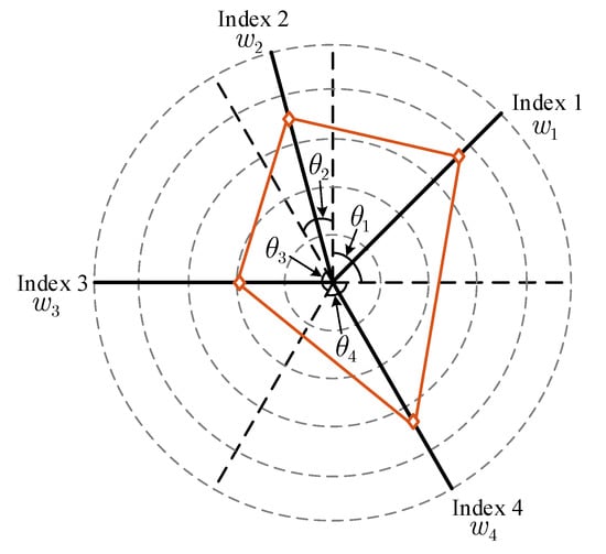
Figure 2.
Radar chart analysis method with the performance metric cluster.
Note that we define the weight of each indicator in the cluster of performance metrics for BPMSM to be the same; thus, the above radar chart can be converted into a regular polygon form.
2. Configuration and Rotor Magnetization
2.1. Configuration Selection of BPMSM
The concept of separated double winding is normally adopted to design BPMSM for a maglev centrifugal pump [21]. The equation describes that the two winding systems (-pole-pair drive winding and -pole-pair suspension winding) must be mutually related so that both torque and suspension forces can be built up with the same rotor. The number of pole pairs of the permanent magnet (PM) rotor always corresponds to the drive winding.
Due to the topology of BPMSM, concentrated coils are mainly used to build the windings. A concentrated coil includes exactly one useful tooth per pole. However, coils can be constructed in the same way but with multiple teeth in one pole. This type of coil is referred to as an expansion of concentrated coil [18]. In order to achieve the best possible winding utilization with concentrated coils, the number of slots N must be selected as small as possible. Better winding utilization can also be achieved by enclosing several useful teeth with extended concentrated coils.
For a symmetrical winding distribution (S) in the stator, the number of slots per pole q must be an integer. The symmetrical winding distribution means that each stator pole is enclosed by a coil assigned to it. The individual coils are all constructed in the same way.
where the subscripts and denote suspension system and drive system, respectively. When choosing an asymmetrical winding structure, the number of slots per pole q must also be an integer, which is described by Equation (10). Compared to the symmetrical winding distribution, the asymmetrical winding structure has the advantage that the same number of stator poles can be generated with half as many coils and slots, thus leading to simpler motor configurations.
According to Bösch’s research [18] and considering the properties based on the cluster of performance metrics, practical configurations of BPMSM for a maglev centrifugal pump are summarized as follows Table 1.

Table 1.
Practical motor configurations of BPMSM.
In this research, a candidate design (rated power 200 W) of BPMSM for a maglev centrifugal pump with the motor configuration (see Figure 1) is adopted as an exemplary object to illustrate the design methods.
2.2. Rotor Magnetization Selection
After the motor configuration was selected, the rotor magnetization should be determined sequentially. In contrast to the build-up of active radial suspension force and torque, the passive axial and tilting stiffness cannot be directly influenced by a corresponding current supplied to the suspension or drive windings. They are largely determined by the rotor magnetization, as well as the geometry of the rotor and stator. The geometric design of the rotor and stator will be introduced in the next section.
As illustrated in Figure 3, three different magnetization methods are presented for the selected two-pole rotors: sinusoidal magnetization, diametric magnetization, and radial magnetization. To determine which magnetization method is most suitable for BPMSM, 3-D FEM simulation was utilized to calculate motor properties based on the cluster of performance metrics under different rotor magnetization methods. During the simulations, the stator was modeled in a temple design [4] with 35CS300 non-oriented electrical steel. N38 NdFeB was chosen as the PM material for all rotors. The rotor yoke was made from S10C steel, and the best ratio of rotor yoke thickness to PM material was selected [30]. Suspension and drive windings (enameled wire with nominal diameters of 0.38 mm and 0.62 mm) were modeled as and turns per phase, respectively. The simulations relate to the approximate initial values of geometric data in Table 2, which were obtained by the classic design methods for ordinary AC motors [24]. Note that the results also retain their validity when all geometric dimensions are scaled with one factor.
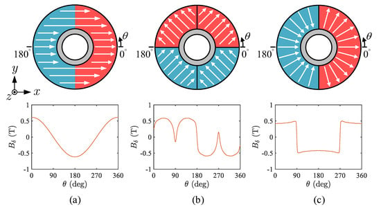
Figure 3.
Two-pole rotors with different magnetization methods. (a) Sinusoidal magnetization. (b) Diametric magnetization. (c) Radial magnetization.
The comparison of suspension properties among three magnetization methods is shown in Figure 4, including axial stiffness (), tilting stiffness ( and ), radial destabilizing stiffness ( and ), and force-current factor (). The comprehensive suspension properties based on the cluster of performance metricsare are presented as a radar map of Figure 5. The evaluation function values of the three magnetization methods were calculated and obtained as: , , and . The results indicate that the sinusoidal magnetized rotor has the relatively best comprehensive suspension performance, while the diametric magnetization is the worst.
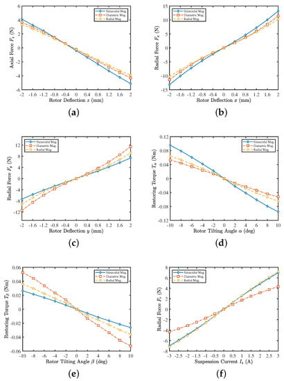
Figure 4.
Three-dimensional FEM simulation results for rotors with different magnetization methods. (a) Axial reluctance force for a rotor deflection in the z-direction. (b) Radial destabilizing force for a rotor deflection in the x-direction. (c) Radial destabilizing force for a rotor deflection in the y-direction. (d) Restoring torque for a rotor tilting around the axis perpendicular to the direction of magnetization. (e) Restoring torque for a rotor tilting around the axis of the magnetization direction. (f) Active radial force for an applied suspension current.
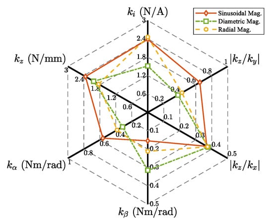
Figure 5.
Comparison of comprehensive suspension performance under different rotor magnetization methods.
According to the distribution of magnetic field density (see Figure 3), the torque performance and controllability of the sinusoidal magnetized rotor are optimal. Combining the above suspension performance, the rotor with sinusoidal magnetization is preferably applied in BPMSM for a maglev centrifugal pump.
3. Geometric Design and Analysis
This section further proposes a complete process (see Figure 6) to design a BPMSM for a maglev centrifugal pump application based on the cluster of performance metrics outlined in Section 2. The design process was established by modifying the well-known procedure for AC machines [24]. The parameterization of BPMSM geometry is depicted in Figure 7. The determination of main dimensions () and design of windings were still based on the tangential stress () or machine constant (C) (see Equation (11)), which means that this design process just follows analytic equations governing the torque performance rather than the suspension performance. In addition, considering the design peculiarities of BPMSM for a maglev centrifugal pump due to the integration of the pump head and sensors, the influence of the ratio of rotor height to diameter, magnetic gap, and stator tooth width will be investigated based on the cluster of performance metrics in the following.
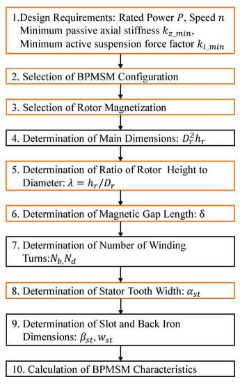
Figure 6.
Design process of BPMSM for a maglev centrifugal pump. The steps marked orange adopt the proposed method based on the cluster of performance metrics, and the remaining ones are based on the design procedure for normal AC motors [24].
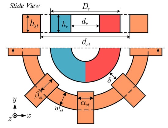
Figure 7.
Parameterization of BPMSM geometry.
3.1. Ratio of Rotor Height to Diameter
The passive properties of BPMSM are predominantly influenced by the slice geometry. One of the most important parameters is the ratio of rotor height to diameter (). To determine the appropriate ratio of rotor height to diameter, 3-D FEM simulations have been conducted. The rotor diameter was fixed at 29 mm in the simulations, and stator tooth height was kept consistent with the change of the rotor height .
The motor properties based on the cluster of performance metrics under different rotor heights are shown in Figure 8, and the corresponding changes of stiffness and factors are displayed in Figure 9. It can be seen that axial and tilting stiffness have similar change trends with the increase of rotor height, and these two factors have a close optimal ratio of rotor height to diameter. Besides, the ratio of axial and radial stiffness is approximately proportional to , and the force-current factor and torque constant are approximately proportional to and , respectively.
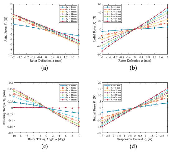
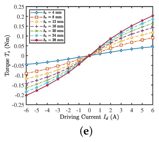
Figure 8.
Three-dimensional FEM simulation results for different rotor heights . (a) Axial reluctance force for a rotor deflection in the z-direction. (b) Radial destabilizing force for a rotor deflection in the x-direction. (c) Restoring torque for a rotor tilting around the axis perpendicular to the direction of magnetization. (d) Active radial force for an applied suspension current. (e) Active torque for an applied drive current.
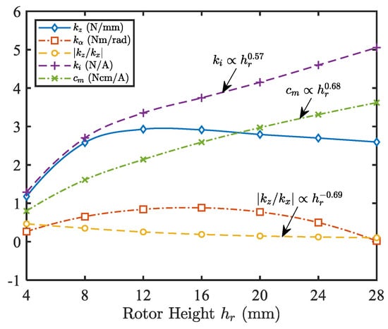
Figure 9.
Motor properties under different rotor heights . The rotor diameter is 29 mm.
For BPMSM used in a maglev centrifugal pump, higher design values of , (indicate better anti-disturbance performance), (better controllability), and (higher load capacity) are expected. Considering the above properties and excellent suspension stability has the highest priority, the optimal ratio of rotor height to diameter is recommended as:
3.2. Magnetic Gap Length
Another important design element of BPMSM is the magnetic gap length. Due to the application in a maglev centrifugal pump, a larger magnetic gap (typically greater than 2 mm) is required to ensure the installation of a pump head. However, the magnetic gap length significantly affects the passive and active properties. To further clarify the quantitative influence of magnetic gap length on motor performance, the properties of BPMSM regarding different magnetic gap lengths were simulated based on the cluster of performance metrics. The stator inner and outer diameters were simultaneously increased in the simulations to ensure the constant radial thickness of the stator.
The detailed passive and active characteristics are illustrated in Figure 10, and the variations of stiffness and factors with magnetic gap lengths are shown in Figure 11. Although there is a slight increase in (proportional to ), which is somewhat beneficial for controllability, the axial stiffness , tilting stiffness , the force-current factor , and torque constant all decrease in proportion to , , , and , respectively. Besides, the passive properties decrease significantly as the magnetic gap length increases. Therefore, if the installation space of the pump head can be further reduced due to the improvement of its manufacturing materials, the performance of BPMSM for a maglev centrifugal pump will be greatly improved. In our research, considering the radial thickness of the pump casing (1.2 mm), rotor coating material (1.2 mm), and physical suspension gap (0.9 mm) [29], the magnetic gap length should be greater than 3.3 mm. Additionally, considering installation errors, mm was selected in the designed candidate (see Table 2).
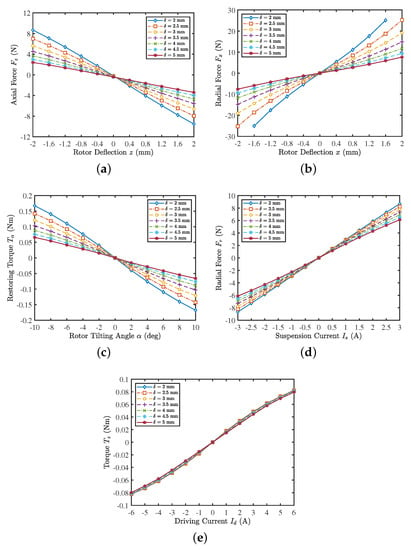
Figure 10.
Three-dimensional FEM simulation results for different magnetic gap lengths . (a) Axial reluctance force for a rotor deflection in the z-direction. (b) Radial destabilizing force for a rotor deflection in the x-direction. (c) Restoring torque for a rotor tilting around the axis perpendicular to the direction of magnetization. (d) Active radial force for an applied suspension current. (e) Active torque for an applied drive current.
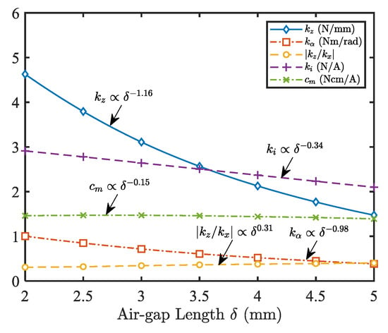
Figure 11.
Motor properties under different magnetic gap lengths .

Table 2.
Parameters of BPMSM.
3.3. Stator Tooth Width
The stator tooth shape of BPMSM for a maglev centrifugal pump is different from that of ordinary AC motors. Considering the installation of radial position sensors and optimization of loss [18], closed or semi-closed arc-shaped stator teeth are no longer suitable; instead, practical flat straight stator teeth are employed (see Figure 1). The stator tooth width is a key dimension that determines the size of slot space and the properties of BPMSM. Three-dimensional FEM simulations based on the cluster of performance metrics under different stator tooth widths have been conducted for the comparison of motor properties.
The simulation results are displayed in Figure 12 and Figure 13. The results show that the increase in stator teeth width contributes to the improvement of the suspension performance (, , and ). Torque constant is hardly affected by stator tooth width. Additionally, the increase of stator tooth width will cause the radial unstable force to increase rapidly (), which is not conducive to the active suspension control of the rotor. In the practical design, a larger stator tooth width is preferred considering the installation of radial position sensors and the winding slot space. Since the diameter of the sensing coil for eddy current sensors in our prototype is 6.5 mm, the stator tooth width is chosen to be mm in the designed candidate (see Table 2), which has almost reached the upper limit.
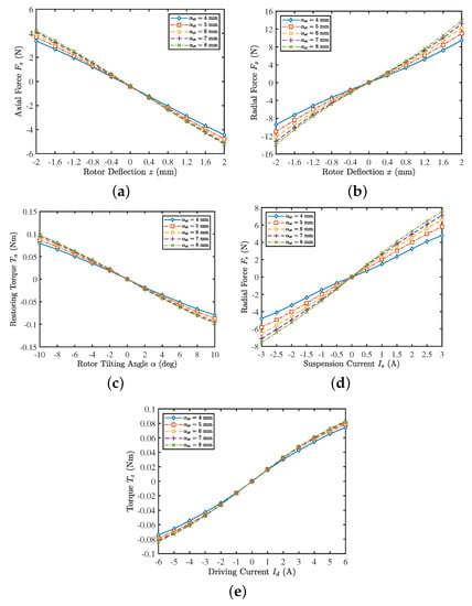
Figure 12.
Three-dimensional FEM simulation results for different stator tooth widths . (a) Axial reluctance force for a rotor deflection in the z-direction. (b) Radial destabilizing force for a rotor deflection in the x-direction. (c) Restoring torque for a rotor tilting around the axis perpendicular to the direction of magnetization. (d) Active radial force for an applied suspension current. (e) Active torque for an applied drive current.
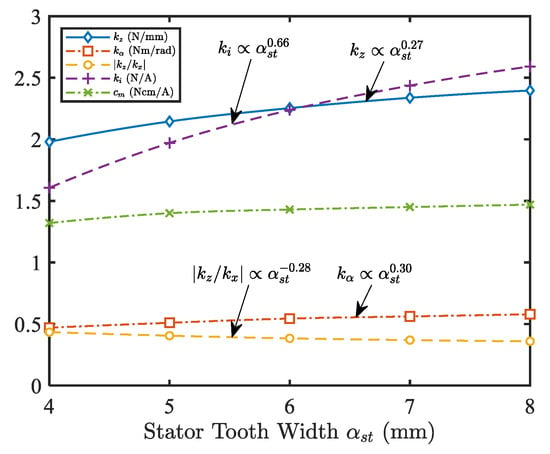
Figure 13.
Motor properties under different stator tooth widths .
4. Results
A designed candidate of BPMSM for a maglev centrifugal pump has been selected according to the design techniques based on the cluster of performance metrics given in the previous sections. Its key parameters are shown in Table 2. The comparison of various performance indicators between initial and designed candidate are presented in Figure 14. It can be seen that most performance indicators have been significantly improved (axial stiffness , tilting stiffness , , force-current factor , and torque constant increased by about 29%, 38%, 33%, 31%, and 21%, respectively). Despite a certain drop in ratio of axial stiffness to radial instability stiffness and (decreased by approximately 18% and 24%, respectively), is increased; thus, a PID controller or other advanced control methods can still ensure excellent radial suspension performance [11]. As a result, the evaluation function value increased by about 15% (from to ), indicating that the comprehensive performance of the designed candidate has been greatly improved, which verifies that the proposed design methods based on the cluster of performance metrics can obtain a better initial design.
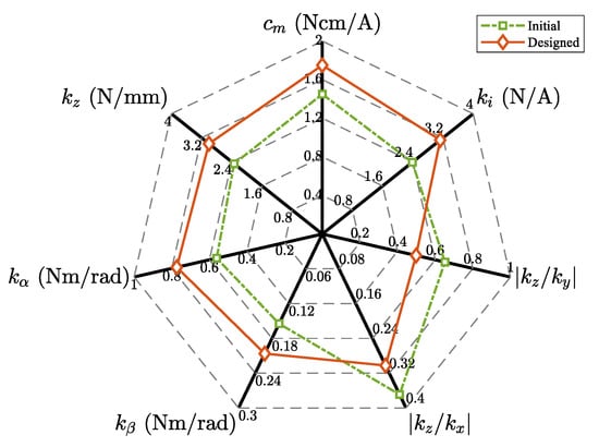
Figure 14.
Comparison of comprehensive performance between the initial and designed candidate.
5. Conclusions
This paper has presented a particular cluster of performance metrics together with evaluation and design techniques targeting on the development and research of BPMSM for a maglev centrifugal pump. Through the analysis of simulation results, the main conclusions are given as follows:
- (1)
- The unique cluster of performance metrics for BPMSM, including passive stiffness (, , , , and ) and active factors ( and ), was identified and used to guide and evaluate the design process.
- (2)
- An evaluation function based on the performance metric cluster and radar chart analysis was constructed.
- (3)
- Practical motor configurations for BPMSM were suggested. Three different rotor magnetization methods were compared on multiple motor properties through FEM, and the sinusoidal magnetized rotor is most suitable for BPMSM.
- (4)
- The complete design process of BPMSM for a maglev centrifugal pump is introduced. Key differences in the design considerations of BPMSM were analyzed, and the determination or quantitative laws of three crucial geometric parameters (ratio of rotor height to diameter , magnetic gap length , and stator tooth width ) were presented.
- (5)
- The better results (, , , , , and increased by about 29%, 38%, 33%, 31%, 21%, and 15%, respectively) of the designed candidate verify the effectiveness of the design techniques.
The proposed methods will provide a comprehensive guideline for designing initial parameters of BPMSM for a maglev centrifugal pump. Systematic optimization design (transient performance of suspension force and torque, efficiency, etc.) is considered as a future research.
Author Contributions
Conceptualization, Y.Z. and L.H.; methodology, Y.Z.; software, Y.Z.; validation, L.H.; investigation, Y.Z.; data curation, Y.Z.; writing—original draft preparation, Y.Z.; writing—review and editing, R.S.; visualization, R.S.; supervision, X.R.; funding acquisition, X.R. All authors have read and agreed to the published version of the manuscript.
Funding
This research was funded by Zhejiang Provincial Natural Science Foundation of China (Grant No. LY19E050015) and Science Fund for Creative Research Groups of National Natural Science Foundation of China (Grant No. 51821093).
Institutional Review Board Statement
Not applicable.
Informed Consent Statement
Not applicable.
Conflicts of Interest
The authors declare no conflict of interest.
References
- Shinshi, T.; Yamamoto, R.; Nagira, Y.; Asama, J. A Bearingless Slice Motor with a Solid Iron Rotor for Disposable Centrifugal Blood Pump. In Proceedings of the 2018 International Power Electronics Conference (IPEC-Niigata 2018-ECCE Asia), Niigata, Japan, 20–24 May 2018; pp. 4016–4019. [Google Scholar] [CrossRef]
- Puentener, P.; Schuck, M.; Kolar, J.W. The Influence of Impeller Geometries on Hemolysis in Bearingless Centrifugal Pumps. IEEE Open J. Eng. Med. Biol. 2020, 1, 316–323. [Google Scholar] [CrossRef]
- Peralta, P.; Wellerdieck, T.; Steinert, D.; Nussbaumer, T.; Kolar, J.W. Ultra-High Temperature (250 °C) Bearingless Permanent Magnet Pump for Aggressive Fluids. IEEE/ASME Trans. Mechatron. 2017, 22, 2392–2394. [Google Scholar] [CrossRef]
- Puentener, P.; Hoffmann, F.; Menzi, D.; Steinert, D.; Kolar, J.W. Homopolar bearingless slice motor in temple design. In Proceedings of the 2017 IEEE International Electric Machines and Drives Conference (IEMDC), Miami, FL, USA, 21–24 May 2017; pp. 1–7. [Google Scholar] [CrossRef]
- Puentener, P.; Schuck, M.; Steinert, D.; Nussbaumer, T.; Kolar, J.W. A 150,000-r/min Bearingless Slice Motor. IEEE/ASME Trans. Mechatron. 2018, 23, 2963–2967. [Google Scholar] [CrossRef]
- Puentener, P.; Schuck, M.; Kolar, J.W.; Steinert, D. Comparison of Bearingless Slice Motor Topologies for Pump Applications. In Proceedings of the 2019 IEEE International Electric Machines Drives Conference (IEMDC), San Diego, CA, USA, 12–15 May 2019; pp. 9–16. [Google Scholar] [CrossRef]
- Gruber, W.; Radman, K. Modeling and Realization of a Bearingless Flux-Switching Slice Motor. Actuators 2017, 6, 12. [Google Scholar] [CrossRef]
- Nguyen, H.P.; Nguyen, X.B.; Bui, T.T.; Ueno, S.; Nguyen, Q.D. Analysis and Control of Slotless Self-Bearing Motor. Actuators 2019, 8, 57. [Google Scholar] [CrossRef] [Green Version]
- Zhang, S.; Luo, F.L. Direct Control of Radial Displacement for Bearingless Permanent-Magnet-Type Synchronous Motors. IEEE Trans. Ind. Electron. 2009, 56, 542–552. [Google Scholar] [CrossRef]
- Xiao, D.S.; Huang, Q.Z.; Pan, W. Decoupling control of bearingless permanent magnet-type synchronous motor using artificial neural networks-based inverse system method. Int. J. Model. Identif. Control 2009, 8. [Google Scholar] [CrossRef]
- Sun, X.; Chen, L.; Yang, Z. Overview of Bearingless Permanent-Magnet Synchronous Motors. IEEE Trans. Ind. Electron. 2013, 60, 5528–5538. [Google Scholar] [CrossRef]
- Sun, X.; Chen, L.; Jiang, H.; Yang, Z.; Chen, J.; Zhang, W. High-Performance Control for a Bearingless Permanent-Magnet Synchronous Motor Using Neural Network Inverse Scheme Plus Internal Model Controllers. IEEE Trans. Ind. Electron. 2016, 63, 3479–3488. [Google Scholar] [CrossRef]
- Hao, Z.; Zhu, H.; Cheng, Y.; Huang, L. Speed Control of Bearingless Permanent Magnet Synchronous Motor Based on Flux Strengthening and Voltage Regulation. IEEE Access 2018, 6, 72392–72401. [Google Scholar] [CrossRef]
- Zhang, W.; Zhu, H.; Xu, Y.; Wu, M. Direct Control of Bearingless Permanent Magnet Slice Motor Based on Active Disturbance Rejection Control. IEEE Trans. Appl. Supercond. 2020, 30, 1–5. [Google Scholar] [CrossRef]
- Raggl, K.; Warberger, B.; Nussbaumer, T.; Burger, S.; Kolar, J.W. Robust Angle-Sensorless Control of a PMSM Bearingless Pump. IEEE Trans. Ind. Electron. 2009, 56, 2076–2085. [Google Scholar] [CrossRef]
- Wellerdieck, T.; Nussbaumer, T.; Kolar, J.W. Angle-Sensorless Zero- and Low-Speed Control of Bearingless Machines. IEEE Trans. Magn. 2016, 52, 1–4. [Google Scholar] [CrossRef]
- Hua, Y.; Zhu, H. Rotor radial displacement sensorless control of bearingless permanent magnet synchronous motor based on MRAS and suspension force compensation. ISA Trans. 2020, 103. [Google Scholar] [CrossRef]
- Bösch, P.N. Lagerlose Scheibenläufermotoren Höherer Leistung. Ph.D. Thesis, ETH Zurich, Zurich, Switzerland, 2004. [Google Scholar] [CrossRef]
- Silber, S.; Amrhein, W.; Bosch, P.; Schob, R.; Barletta, N. Design aspects of bearingless slice motors. IEEE/ASME Trans. Mechatron. 2005, 10, 611–617. [Google Scholar] [CrossRef]
- Bartholet, M.T.; Nussbaumer, T.; Silber, S.; Kolar, J.W. Comparative Evaluation of Polyphase Bearingless Slice Motors for Fluid-Handling Applications. IEEE Trans. Ind. Appl. 2009, 45, 1821–1830. [Google Scholar] [CrossRef]
- Raggl, K.; Nussbaumer, T.; Kolar, J.W. A Comparison of Separated and Combined Winding Concepts for Bearingless Centrifugal Pumps. J. Power Electron. 2009, 9, 243–258. [Google Scholar] [CrossRef]
- Pan, W.; Zhu, H.; Li, H. Design and Optimization of Bearingless Permanent Magnetic Synchronous Motors. IEEE Trans. Appl. Supercond. 2016, 26, 1. [Google Scholar] [CrossRef]
- Sun, Y.; Su, B.; Sun, X. Optimal Design and Performance Analysis for Interior Composite-Rotor Bearingless Permanent Magnet Synchronous Motors. IEEE Access 2019, 7, 7456–7465. [Google Scholar] [CrossRef]
- Pyrhonen, J.; Jokinen, T.; Hrabovcova, V. Design of Rotating Electrical Machines, Second Edition; John Wiley & Sons, Ltd.: Hoboken, NJ, USA, 2013. [Google Scholar] [CrossRef]
- Farhan, A.; Johnson, M.; Hanson, K.; Severson, E.L. Design of an Ultra-High Speed Bearingless Motor for Significant Rated Power. In Proceedings of the 2020 IEEE Energy Conversion Congress and Exposition (ECCE), Detroit, MI, USA, 11–15 October 2020; pp. 246–253. [Google Scholar] [CrossRef]
- Chen, J.; Fujii, Y.; Johnson, M.W.; Farhan, A.; Severson, E.L. Optimal Design of the Bearingless Induction Motor. IEEE Trans. Ind. Appl. 2021, 57, 1375–1388. [Google Scholar] [CrossRef]
- Raggl, K. Integrierte Lagerlose Pumpsysteme Hoher Leistungsdichte. Ph.D. Thesis, ETH Zurich, Zurich, Switzerland, 2009. [Google Scholar] [CrossRef]
- Nussbaumer, T.; Karutz, P.; Zurcher, F.; Kolar, J.W. Magnetically Levitated Slice Motors—An Overview. IEEE Trans. Ind. Appl. 2011, 47, 754–766. [Google Scholar] [CrossRef]
- Zhang, Y.; Ruan, X.; Hu, L.; Li, L.; Li, B.; Chen, X. Active disturbance rejection control for bearingless permanent-magnet slice motor based on nonlinear phase-locked loop observer. Proc. Inst. Mech. Eng. Part J. Mech. Eng. Sci. 2020. [Google Scholar] [CrossRef]
- Zhu, H.; Li, F. Optimization Design of Bearingless Permanent-Magnet Slice Motor. IEEE Trans. Appl. Supercond. 2016, 26, 1–4. [Google Scholar] [CrossRef]
Publisher’s Note: MDPI stays neutral with regard to jurisdictional claims in published maps and institutional affiliations. |
© 2021 by the authors. Licensee MDPI, Basel, Switzerland. This article is an open access article distributed under the terms and conditions of the Creative Commons Attribution (CC BY) license (https://creativecommons.org/licenses/by/4.0/).