Abstract
Increasing performance in modern hydraulics is achieved by a close investigation of possible enhancements of its components. Prior research has pointed out that electromechanical actuators can form suitable alternatives to hydraulically piloted control systems. Since the requirements at these actuation systems depend on the operating conditions of the system, each actuator can be optimized to the respective hydraulic system. Considering that many different conceptual designs are suitable, the phase of conceptual design plays a decisive role during the design process. Therefore, this paper focuses on the process of developing new conceptual designs for electromechanical valve actuation systems using the method of function structures. Aiming to identify special design features, which need to be considered during the design process of electromechanical actuation systems, an exemplary actuator was designed based on the derived function structure. To highlight the potential of function structures for the development of new electromechanical valve actuation systems, two principal concepts, which allow the reduction of the necessary forces, have been developed by extending the function structure. These concepts have been experimentally investigated to identify their advantages and disadvantages.
1. Introduction
In modern hydraulic systems, most large-sized control valves are operated via smaller pilot valves. This type of actuation is characterized by high attainable forces over large possible strokes. In order to impress sufficient forces and, therefore, ensure a reliable switching process, a minimum working pressure difference over the valve of approximately 4 bar is demanded [1,2,3]. If this minimum working pressure difference is not ensured, the resulting force is insufficient to switch the valve, and the pilot valve cannot be internally supplied [1,2,3]. Instead, it needs to be supplied by an external pilot circuit, which is commonly operated as a constant pressure system [1]. As an alternative to a pilot operation, new electromechanical actuation systems can be developed, enhancing the energy efficiency of the system. Currently, several electromechanical actuators for large-sized valves are offered by different companies. They are presented with a focus on their performance in different publications, such as [4,5]. Most concepts for the application of large forces are based on an electric motor, of which the rotary movement is transformed into a linear movement by means of a rack-pinion combination.
As the requirements for the actuation system are set by the operation conditions of the valve, the actuation system needs to be tailor-made for each system. Besides the necessary actuation forces and also the realizable strokes, the actuator’s dynamic and position accuracy can differ depending on the planned application. Therefore, there is not only the demand for fully developed electromechanical actuators but also for the know-how to develop actuators specifically designed for the application. In order to avoid overperforming highly integrated and cost-intensive solutions, rather specific solutions can be developed, which entirely fulfill the specific requirements. Besides the definition of the requirements, the actuator control and the design of the electromechanical transducer, as well as the conceptual design, play an important role in the development of new electromechanical valve actuators. In contrast to other papers, the present work focuses mainly on the last point and also describes some constructive details, which need to be considered during the design of electromechanical valve actuation systems to prevent additional forces during operation. Therefore, this paper is intended to serve as a basis for further developments of innovative conceptual designs of electromechanical valve actuation systems.
Using the design method of function structures according to VDI 2222 methodic development of solution principles [6], Pahl/Beitz [7,8], or Koller [9], a comprehensive analysis of the valve and its actuation system has been carried out. While the graphical representation is extended by further generally valid functions, the potential of function structures for the design of innovative valve actuation systems is shown, and more innovative conceptual designs for valve actuation systems can be derived, taking into account the valve and the whole actuation system. Two exemplary actuator enhancements, which have been proposed in the conference paper [10] and serve to act against the valves’ spring forces, have been developed and investigated experimentally in this paper. Using these enhancements, the necessary actuation force can be strongly reduced, and further actuator designs are possible.
2. Overall Function of a Directional Control Valve
Using the design principles of function structures, the overall function of a technical system can be divided into generally valid functions. Table 1 displays and explains the symbols used for the generally valid functions in the presented paper. Any overall function can be subdivided into generally valid functions until a sufficient function structure, in accordance with the intended design process, is obtained.

Table 1.
Symbols of generally valid functions in accordance with reference [9].
The overall function of a control valve can be phrased as “Opening/Closing of different flow paths” [11]. As hydraulic systems are often embedded within an electrical higher-level control system, this main function can be further extended to the “Opening/Closing of different flow paths according to electrical control signals.” This main function can be divided into two sub-functions, the “Conduction off hydraulic energy depending on position” and the “Positioning of the spool according to an electrical signal.” See Figure 1 [12].

Figure 1.
The structure of the general function.
The conduction of hydraulic energy is performed by the geometry of the spool and its positioning by the actuation system. Since the spool is moved by the impression of a force, the function can be reformulated as “Applying force to the spool according to an electrical signal.”
3. Design of New Valve Actuation Systems
Every actuator needs to overcome any forces opposing the intended movement to guarantee functionality. Therefore, when designing an actuator, it is inevitable to analyze the forces acting on the spool. In Figure 2, the forces acting on the spool of a pilot-operated 4/3 directional control valve are shown as examples.
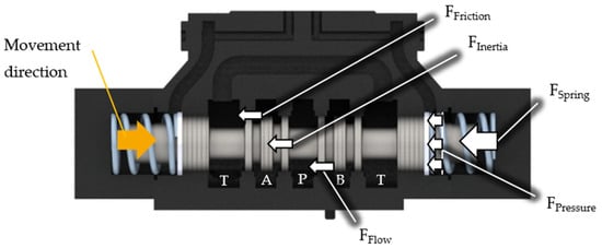
Figure 2.
Forces at the spool in accordance with reference [13,14,15].
Besides the smaller forces such as friction FFriction and inertia forces FInertia, the actuator also needs to overcome the spring FSpring and flow forces FFlow.
The friction forces can further be subdivided into Coulomb friction and fluid friction. Whereas the Coulomb friction is caused by radial forces, which can be prevented by circumferential grooves, the fluid friction is caused by the relative movement between the spool and the housing [13,16,17,18]. In the case of electromechanical actuators, additional sealing should be considered to prevent external leakage leading to further friction forces.
The inertia forces FInertia depend on the spool’s mass and acceleration. They are consequently defined by the design of the housing and the spool, as well as on the switching time.
The spring forces FSpring must be high enough for the valve to close at any given operation condition. As the compression spring is assembled with a preload and the stroke is limited to the centered position, the discontinuous forces prevent the spool from overshooting [13,19].
The flow forces FFlow, which can have a decisive share in the total forces, generally act in the closing direction and depend on the operating point of the valve [20,21,22,23]; depending from the valve’s size, they can be up to several hundred newtons [24,25,26]. This is why the valve’s operation profile plays an important role during the design process. It is precisely this fact that makes electromechanical actuators extremely interesting for systems that rely on a separate pilot circuit due to a low-pressure difference over the valve. On the one hand, the pilot circuit can be avoided, which makes the whole system less complex and cheaper. On the other hand, the pilot circuit is necessary because there is an insufficient pressure difference over the valve during the switching process. This will lead to only small flow rates and, therefore, to small flow forces. In an ideal flow-controlled system, the main pump will even be completely swung back before the valve is switched, and therefore, no flow forces will occur. Therefore, the application of electromechanical actuators in these systems is advantageous since they reduce the whole system’s complexity and can be designed for smaller forces.
The additionally inherent force FPressure, which is caused as fluid is displaced out of the passive pilot chamber during the spool’s movement, can nearly be avoided in the case of electromechanical actuators, as will be explained in Section 3.3.
3.1. Function Structure of an Electromechanical Actuated Large-Sized Valve
Based on the structure with two main functions proposed in Figure 1, the function structure of a 4/3 directional control valve is displayed in Figure 3, using the generally valid functions in accordance with Table 1.
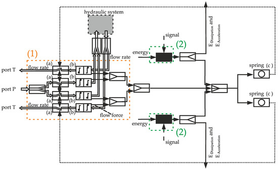
Figure 3.
The function structure of a valve and its actuation system.
The system of a “valve and its actuation system” can be divided into different subsystems. As shown in Figure 3, Subsystem (1) represents the functionality derived from the spool’s geometry. Flow entering the system via port P is guided and transmitted by the metering edges to the working ports (a) of the valve. A part of the carried energy is transformed into mechanical energy (b), which acts as a flow force on the spool. Once the fluid leaves Subsystem (1), it enters an arbitrary hydraulic system. Any fluid flowing back into the tank leads to additional flow forces.
The force applied by the actuation system during positioning needs to be larger than all resistive forces acting on the spool combined. As previously shown in Figure 2, the forces consist of flow forces FFlow, friction forces FFriction, inertia forces FInerta, spring forces FSpring, and pressure forces FPressure resulting from the hydraulic resistance of the drain line of the passive pilot chamber. During the movement, a part of the actuator imprinted force is used to overcome the friction and further resistance forces, which is why a dissipation energy EDissipation is leaving the system. As flow forces are regarded as generated forces, they are displayed as the energy that needs to be subtracted from the energy applied by the actuation system. Subtracting all losses and the energy, which is used to accelerate the spool (EAcceleration), the remaining mechanical energy is stored in the springs (c). This energy is proportional to the stroke of the spool, which is why an information flow is drawn from the springs (c) towards the metering edges (a). If the actuation force is reduced, this stored energy is released, thus centering the spool.
Subsystem (2) represents the actuator, which function structure is shown in Figure 4.
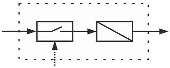
Figure 4.
The minimal function structure of an actuation system according to [27,28].
Each actuator is made up of at least one switch and an energy converter [27,28]. This switch could be a pilot valve within a pilot operation system, where the energy conversion occurs in the pilot chamber. In the case of an electromechanical valve actuation system, it would, in turn, be an electromechanical converter, such as a solenoid or an electrical motor. An evaluation of different electromechanical converters was carried out to analyze the suitability of different electromechanical converters for the desired application. As a result, an electrical motor, followed by a mechanical component to convert rotatory into translatory movement, represents the optimal concept.
3.2. Electromechanical Valve Actuation System
A design of a prototype of an electromechanical valve actuation system has been created to identify crucial design details, see Figure 5. In this design, a stepper motor (1) carries out the active motion of the spool. A steep-threaded rod (2) and nut (3) convert the rotary energy to linear motion. The demonstrator includes sensors necessary for measuring the force (4) and the displacement (5). As the intended usage is for large-sized directional control valves of nominal size 25 operated in a flow-controlled system, the actuation system can exert a force up to 500 N. Figure 5 shows that the electromechanical actuator is mounted on the outside of the valve, which allows compatibility with any common valve design by adjusting the valve connector piece (6). As the steep-threaded rod is not self-locking, the spool is centered by the springs if the stepper motor is deactivated.
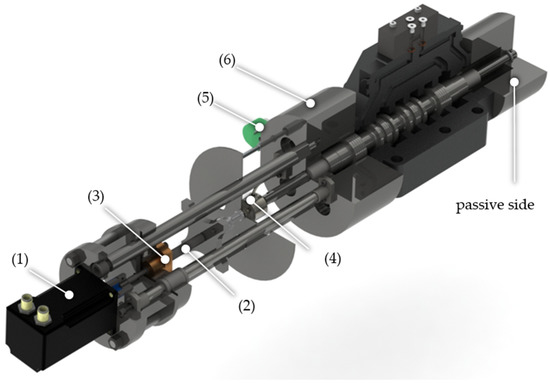
Figure 5.
The designed electromechanical valve actuation system.
3.3. Design Details of Electromechanical Valve Actuation System
If the valve actuation system is designed independently from the valve itself, care must be taken in the design process as to not cause additional forces. Features intended to prevent this are highlighted in Figure 6, which shows a sectional view of a regular pilot-operated valve.
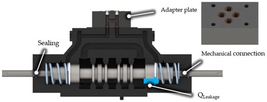
Figure 6.
Special design details for an externally mounted electromechanical actuation system.
The valve spool is extended at both ends with a rod, forming a connection to the electromechanical actuation system outside of the valve, allowing the transmission of tensile and compressive forces. Actuation systems, which are able to induce both forces, can be attached only on one side of the valve. Since the mechanical connection reduces the working surface of the spool on which the pressure acts, it must be implemented on both sides to balance the forces on the spool. Furthermore, the pilot chambers on both sides must contain equal pressures and so are short-circuited. As the valve actuation system is designed to be a mere attachment, an integrated circuit between the pilot chambers is not possible; therefore, an adapter plate is mounted to the valve, replacing the pilot valve, and using the existing pilot channels to short circuit the pilot chambers. The same effect could be reached by boring through the axis of the spool itself.
During the movement of the spool, the volume of one chamber is expanded, whereas the volume of the other is compressed. To avoid an additional counteracting force by the increase in pressure, the chamber fluid must be able to enter or exit the chambers. By short-circuiting both pilot chambers with the adapter plate, the displaced volume of one chamber is compensated in the other, thus maintaining a constant volume and a compensation volume can be avoided. The fluid just needs to overcome the inherent losses caused by the oscillation between the chambers. This results in a small pressure difference between the pilot chambers. To investigate this effect, the actuator was operated at variable speeds, and the respective required force during the movement was measured. This force is displayed over the position of the spool for different velocities in Figure 7a. In the measurement results also the spring preload of around 250 N, the spring stiffness and the friction forces can be identified. The friction forces of around 40 N are represented by the hysteresis between the upper and lower lines of the curves, representing the forward and backward movement.
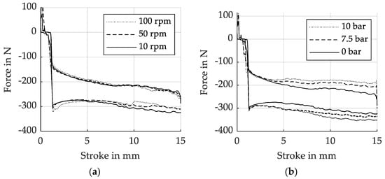
Figure 7.
(a) The influence of actuator speed on necessary forces. (b) The relation between pressure level and friction forces.
As the results in Figure 7a shows, the necessary force to move the spool does not increase significantly, even at tenfold the actuator’s speed. Consequently, it is concluded that the resulting effect is negligible if a sufficient compensation channel is actualized.
To avoid external leakage, additional sealing must be added to the caps. These, however, lead to additional friction forces, which must, in turn, be overcome by the actuation system. The friction forces are dependent on the pressure within the pilot chambers. To investigate these effects further, measurements were carried out. The force required according to different pressure levels in the chambers is shown in Figure 7b.
Figure 7b shows that the pressure level is non-negligible and that a mere chamber pressure of 10 bar requires a significant increase in force provided by the actuation system, which can be seen due to the increased hysteresis between the upper and lower lines of the curves of forward and backward movement. In this case, friction forces have nearly doubled, achieving values of 80 N. The pressure in the pilot chambers, therefore, must be reduced as much as possible. Since there is a leakage flow over the spool, the pressure in the pilot chamber is adjusted to the pressure at the T port of the valve. Accordingly, the maximum pressure in the tank line must be considered during the design of externally attached actuation systems. If the pressure in the tank line can reach high values, an additional drain line within the adapter plate can be used to ensure sufficiently low-pressure levels in the pilot chambers. The mentioned design details are only valid for independently designed externally attached actuation systems. The development of a pressurizable actuation system would render the added sealing and the drain line redundant. Likewise, the adapter plate is unnecessary if there is an existent direct connection between the pilot chambers.
As the system is designed for ideal flow-controlled systems, no flow forces will occur during the switching process as the flow rate will be reduced as much as possible before the actuation system is activated.
With a valve spool mass of 1.01 kg, a maximum stroke of approximately 11 mm and a maximum switching time of 40 ms, assuming constant acceleration, this results in an acceleration of 13.75 m/s2 and thus an inertial force of 13.88 N, which is approximately 5% of the spring’s preload force. Therefore, the spring forces are the main forces, which need to be overcome by the actuation system.
3.4. Extended Electromechanical Valve Actuation System
The presented actuation system is one possible solution found using only the function structure of a valve and its actuation system, as presented in Figure 3. In Figure 8, the function structure of the “valve and its actuation system” is extended with the additional subsystems (3) and (4).
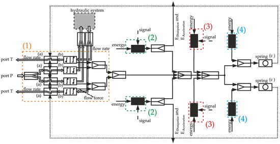
Figure 8.
The extended function structure of “valve and its actuation system”.
Besides the additional subsystems, the function structure remains the same. Subsystem (1) continues to represent the valve and subsystem (2) the main actuator. With this function structure, new valve actuation systems can be derived by combining different subsystems and, therefore, reducing the requirements of the individual actuators. Solutions provided by subsystem (3) cover all actuation systems, which are extended by additional actuators keeping the spool in position once the desired stroke is reached. In this case, the main actuator (2) does not need to continuously apply the required force but only overcome the opposing force shortly. Afterwards, the secondary actuator (3) holds the spool in its position. This could, per example, be achieved by means of clamping. As clamping forces are required perpendicular to the spool’s movement, the actuator (3) only needs to fulfil relatively small strokes. An example of the clamping motion can be seen in piezoelectric inchworm motors.
Solutions derived from subsystem (4), however, are more promising. The springs’ function is to move the spool to one defined position. For a 4/3 directional control valve, said position is centered. More precisely, the spring has two relevant functions. Primarily the spring needs to center the spool in accordance with the operation cycle, and secondarily, they also need to center the spool in case of failure, such as during a power outage. See Figure 9.

Figure 9.
The divided general function of the springs.
While moving the spool into the end position, a part of the energy provided by the actuator is simultaneously used to compress the spring, thus storing energy within. The time dependency between the energy storage and the spool movement can be solved by separating and redistributing the spring functions into separate components. Here, the first function, “centering the spool according to the operation cycle,” can be carried out by the main actuator using a proportional actuator as presented above. The energy stored in the springs is then only used in case of failure, and the springs stay compressed most of the time due to the additional force exerted by subsystem (4). This reduces the force requirements of the main actuator, as the high spring forces are not needed to be overcome during normal operation since they can be temporarily removed. However, these solutions are merely an extension of existing actuator concepts, such as the actuation system presented above based on a stepper motor and a threaded rod or actuation systems similar to those presented in [4,5]. Therefore, these relief systems must be combined with the main actuator used to displace the spool. Thus, they must be designed in such a way that the assembly is compatible with the main actuator.
Two concepts turned out to be the most suitable for this application. In the first solution of a magnetic relief system, the springs are preloaded by the main actuator while being held compressed by solenoids. In the second solution, hydraulic energy is used to compress the springs. The hydraulic relief system corresponds to a spring-returned cylinder, which can preload the spring and hold them compressed if it is pressurized. An evaluation of the independent spring relief systems without other components delivers the identification of the advantages and disadvantages of both proposed concepts.
3.4.1. Magnetic Relief System
In the concept of the magnetic relief system, the additional force of subsystem (4) is applied by a holding solenoid. The spring is thereby kept in a tensioned state as long as the holding solenoid is energized. Holding solenoids are perfectly suited for applying high forces on ferromagnetic bodies over small air gaps. However, if the air gap increases, the magnetic force drops drastically since the magnetic flux through the counterpart falls significantly with increasing gap height. Therefore, holding solenoids are only suitable to hold the compressed springs in position and are not capable of compressing the springs due to the large stroke required. This must be performed by the main actuator, which, therefore, must be designed to overcome the initial spring forces until the solenoid can hold the spring by itself. A sectional view of the designed magnetic relief system is shown in Figure 10.
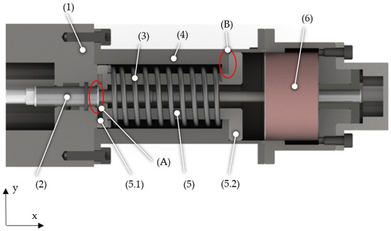
Figure 10.
Sectional view of the magnetic relief system.
The proposed design consists of a valve connector (1), a rod as a mechanical connection to the spool (2), the spring (3), a housing (4), the relief cylinder (5), and the holding solenoid (6). The relief cylinder (5) is assembled by two separate parts (5.1) and (5.2).
The passive side (see Figure 5) of the actuator is used to explain the operating concept of the magnetic relief system since no feed-through of the main drive train needs to be included. The operation method of the active side is identical. The displayed configuration of the magnetic relief system in Figure 10 is the centered spool position. When the spool is deflected in the positive x-direction, a force is transmitted from the actuator through the spool and rod over the shoulder (A) into the relief cylinder (5). This force acts on the spring, which is compressed when the spool is further displaced. During this movement, the air gap between the component (5.2) and the magnet (6) becomes narrower until the magnetic force resulting from the active solenoid is greater than the opposing spring force. As long as the magnet is energized, a force counteracting the centering spring forces is applied, and the spring is held tensioned. The main actuator is now able to freely move the spool, requiring significantly lower forces to do so.
If the magnet is de-energized during the reset process, the magnetic force decreases and the relief cylinder is centered. As a force can be transmitted by the shaft shoulder (A), the spool is also centered during this process. The advantage of this concept is a potential for higher performance since the spring forces do not need to be overcome at every deflection.
Aiming to investigate the relief system, the reset process of the system without attached valves was measured. A set up according to Figure 11 has been build up.
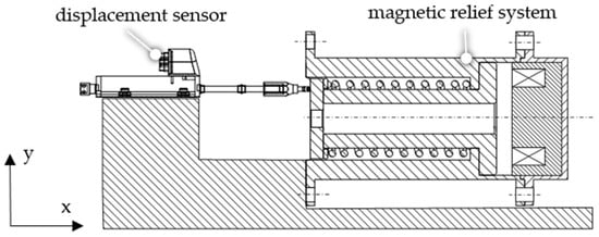
Figure 11.
The systematical measuring set up.
The relief system was displaced manually while the magnet was energized, thus compressing the spring. As the solenoids are deactivated, the effective force on the spring drops and the reset process begins. The data logging started at the time when the solenoid was de-energized, measuring only the reset time. An additional sensor was placed in the power supply line measuring the current of the holding solenoid. The results of the displacement signal and the current signal are shown in Figure 12 and Figure 13. The measurements have been replicated ten times, thus securing a statistical relevance.
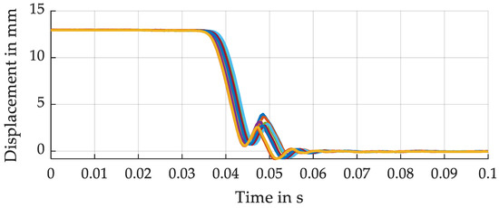
Figure 12.
Measured displacement signals for all measurements.
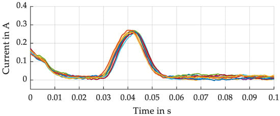
Figure 13.
Measured current signals for all measurements.
With a stroke of approx. 13 mm, the relief system takes 55 ms to reach a displacement of 0 mm. During the reset process, component (5) is accelerated by the spring force and comes to an abrupt stop due to the shaft shoulder (B) as soon as it reaches the original position. As the magnets are deactivated, the electrical current decreases. Due to the inductivity of the solenoid, this does not happen immediately but requires about 20 ms to reach a current of nearly 0 Ampere. The reset system stays motionless during this time-lapse since the current needs to drop below a level in which the resulting force of the holding solenoid is overcome by the spring force. As soon as the reset movement starts at 30 ms, a counter-induction takes place in the holding solenoid, which is why a current of approx. 0.25 Ampere is measured during the movement. This current drops to 0 Ampere while the initial position is reached at about 55 ms.
3.4.2. Hydraulic Relief System
In this solution, a relief system is designed to preload the spring by applying hydraulic energy to an additional chamber. Since the spring forces can be completely ignored during the motion, the forces, which are necessary for the main actuator, can be reduced. This allows the application of smaller electromechanical actuators. A basic design of this relief system is shown in Figure 14.
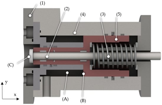
Figure 14.
A sectional view of the hydraulic relief system with marked areas (A–C).
Similar to the magnetic relief system, the hydraulic relief system is placed between the main actuator and the valve. The centering springs are removed from the pilot chambers and incorporated into the relief system. The design consists of a valve adapter (1), a shaft as a mechanical connector (2), a centering spring (3), a housing (4), and a return cylinder (5), which, together with the housing, forms the relief chamber (A). When the relief chamber is pressurized, a force acts on the surface (B) of the cylinder, compressing the spring. This causes the gap between the hard stop (C) and the valve spool to increase. Therefore, the spool is now free to move and is no longer centered by the springs. The relief system needs to be controlled by a hydraulic system, which is shown in Figure 15.
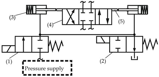
Figure 15.
The schematic layout of the hydraulic relief system.
The pressure supply of the circuit is not further defined, but since the relief system can be activated independently from the valve, it can be diverted from the main system during high-pressure phases or when the valve is closed. An additional hydraulic circuit can therefore be avoided. The relief system is depicted as a spring-returned cylinder (3), which acts on the valve (4) by means of a mechanical connection (5). The hydraulic relief is controlled by two poppet valves. During the loading process, the first valve (1) needs to be opened, while the second valve (2) must be closed. After the relief system is pressurized, both valves must be closed. Regardless of what happens in the hydraulic circuit, the pressure in the relief system will be kept constant. As valve (2) opens, the relief system is connected to the tank to depressurize the relief system. Therefore, the force acting against the springs is reduced, causing the relief cylinder to accelerate in the closing direction. To fulfill safety requirements, the configuration of the first valve should be normally closed and of the second normally opened. Therewith, the relief system is automatically deactivated in case of power failure, thereby centering the spool. In Figure 16 and Figure 17, measurement results of the displacement signal and the pressure inside the relief chamber are shown. The same test rig of Figure 11 is used to carry out the measurements with a different relief system instead. In total, 10 measurements have been conducted and displayed.
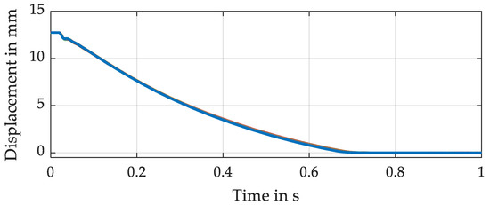
Figure 16.
Measured displacement signals for all measurements.
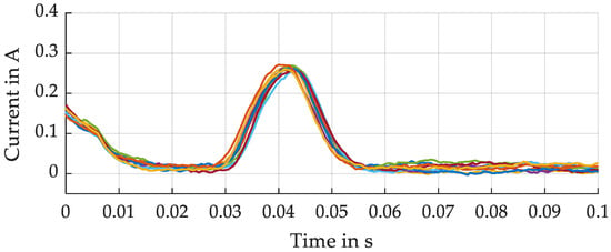
Figure 17.
Measured pressure signals in the relief system for all measurements.
As can be seen, the reset times of the system for displacements of about 13 mm is around 700 ms. A reproducible behavior can be identified, with only small deviations between the measurements, which is why most curves are congruent. During the reset process, the pressure in the relief chamber decreases from around 5 bar to 1 bar. The reaching of the end position can also be identified in the plot of the pressure in the relief chamber. When the end position is reached at 700 ms, the slope of the pressure curve changes drastically.
4. Discussion
The function structure is a vital design method for the design process of innovative electromechanical valve actuation systems. While the investigation of acting forces is indispensable, the function structure allows a far more complete view of the valve and its actuation system during the conceptual design phase. Splitting the system into its generally valid functions allows optimization not restricted to just the reduction of flow forces, which has previously been an effective approach to reduce the necessary forces of valve actuation systems (see references [15,20,26,29]).
The function structure proposed in this paper leads to solutions where the spring forces are compensated, thus reducing the requirements on the main actuator. The two investigated concepts of relief systems show great potential as extensions to new electromechanical valve actuation systems. They are capable of notably reducing the force requirements, which allows the application of smaller electromechanical actuators.
The magnetic relief system has considerably shorter reset times than the hydraulic relief system but depends on the main actuator, which can initially overcome the counteracting spring forces. The magnetic relief system is, therefore, particularly advantageous in use cases where the spring forces account for about half of all acting forces.
In the case of the hydraulic relief system, the spring forces are compensated by hydraulic power, and therefore, no high force main actuator is necessary. Therefore, the hydraulic relief system is particularly interesting where the spring forces make up a significant part of the force to be overcome by the main actuator, which is unable to compress them.
The performance of the reset systems can be modified by suitable changes, for example, by installing a stiffer spring or implementing greater preload forces. In the case of the hydraulic relief system, the time can also be reduced by optimizing the hydraulic system. However, the effort to make it competitive with the magnetic relief is immense.
While it was possible to test the viability of the two concepts, their dynamic performance decreases, due to higher inertial forces, if they are integrated into an actuation system. Therefore, the electromechanical actuation system presented in this paper should be extended by one relief system and optimized to a use case for further investigation concerning the reset time and the actuator performance. Nevertheless, both actuation systems show great potential since they can drastically reduce the actuation force and therefore lead to an increased performance of the main actuators or allow the use of an actuator of a smaller power class.
The concept of the proposed spring relief systems has been derived by the application of the design methodology of function structure, and, even if it may be further extended, the presented function structure already contains some significant correlations that can help during the development of conceptual designs for valve actuation systems. During their design process, the critical design features identified at a prototype of an electromechanical actuation system should be considered, and an investigation of the acting forces as well as the dynamic behavior is inevitable.
5. Conclusions
In the presented paper, the design process of new electromechanical valve actuation systems for large-sized directional control valves are presented. Since the design of the actuator according to the necessary forces and strokes depends on the considered application, each actuator should be tailor-made to the corresponding system. Therefore, the presented paper is intended to provide a general basis for the design of novel valve actuators and focuses on the phase of conceptual design, as well as the identification of basic design features of electromechanical actuators, rather than on the dimensioning of the electromechanical transducer.
The influence of the special design features identified at a conceptual design could be investigated through measurements. While designing externally mounted electromechanical valve actuators, not only the forces acting on the spool need to be considered while dimensioning the electromechanical transducer, but also effects in the pilot chambers must be taken into account. Since additional sealings are necessary, both pilot chambers are to be short-circuited and relieved against the tank in order to decrease the load on the actuator due to the sealing friction forces. Since the volume inside the pilot chambers is expanded and compressed during the movement, short-circuiting is necessary to keep the total volume constant. Therefore, no compensation volume is required.
The basic function structure derived in this paper is used to develop further conceptual designs by extending the function structure by further generally valid functions. By adding an additional force, which is used to pre-compress and maintain compression on the springs respectively, two conceptual designs reducing the necessary force of the main actuator have been derived. The functionality of these concepts has been proved by measurements on designed prototypes. Whereas the magnetic relief system achieves reset times of around 55 ms and is advantageous for use cases, where spring forces account for about half of the required forces, the prototype of the hydraulic relief system has larger reset times and is suited for use cases where the spring forces are the dominant force.
As the proof of concepts is provided, the present research results regarding the conceptual design can be used to develop novel electromechanical actuators for special applications. However, the actuator must be precisely designed to meet the requirements. This must be conducted taking into account the individual valve application and involving a very precise investigation of the requirements by the designer. Nevertheless, the derived function structure can serve as a basis for the further development of innovative valve actuation systems or be extended to develop even more innovative actuation systems.
Author Contributions
Conceptualization, T.V.; methodology, T.V. and K.S.; writing—original draft preparation, T.V.; writing—review and editing, K.S.; visualization, T.V.; supervision, K.S.; project administration, T.V.; funding acquisition, K.S. All authors have read and agreed to the published version of the manuscript.
Funding
The IGF research project 20084/N of the research association Forschungskuratorium Maschinenbau e. V.–FKM, Lyoner Straße 18, 60,528 Frankfurt am Main was supported from the budget of the Federal Ministry of Economic Affairs through the AiF within the scope of a program to support industrial community research and development (IGF) based on a decision of the German Bundestag.
Conflicts of Interest
The authors declare no conflict of interest.
References
- Bauer, G. Ölhydraulik: Grundlagen, Bauelemente, Anwendungen; Vieweg + Teubner; Springer: Berlin/Heidelberg, Germany, 2009. [Google Scholar]
- Rexroth, B. Directional spool valves, pilot-operated, with hydraulic or electro-hydraulic actuation: Type WEH and WH. Available online: https://www.boschrexroth.com/en/xc/myrexroth/mediadirectory?language=de-DE&publication=NET&filterMediatype=1584&search_query=24751&search_action=submit&edition_enum=rd24751 (accessed on 21 April 2021).
- Parker Hannifin GmbH. Directly operated and pilot operated directional control valves: Series D1VW/D1DW/D3W/D3DW/D31DW/D41VW/D81VW/D91VW. Available online: https://www.parker.com/Literature/Hydraulic%20Controls%20Europe/Manuals%20UK/DCV1-662%20UK.pdf (accessed on 21 April 2021).
- Lux, J.; Habegger, C. New generation of intelligent electromechanical valve actuation. In Proceedings of the 11th International Fluid Power Conference, Aachen, Germany, 19–21 March 2018; pp. 394–402. [Google Scholar] [CrossRef]
- Ermert, M. Electromechanical actuator concept for the controlled and direct actuation of a hydraulic main stage. In Proceedings of the 10th International Fluid Power Conference, Dresden, Germany, 8–10 March 2016; Dresdner Verein zur Förderung der Fluidtechnik e.V.: Dresden, Germany, 2016; pp. 503–513. [Google Scholar]
- Methodisches Entwickeln von Lösungsprinzipien: Konstruktionsmethodik; VDI 2222; Verein Deutscher Ingenieure: Berlin, Germany, 1997.
- Pahl, G.; Beitz, W.; Feldhusen, J.; Grote, K.-H. (Eds.) Pahl/Beitz Konstruktionslehre: Methoden und Anwendung erfolgreicher Produktentwicklung, 8th ed.; Springer: Berlin/Heidelberg, Germany, 2013. [Google Scholar]
- Pahl, G.; Peitz, W.; Feldhusen, J.; Grote, K.-H. Engineering Design: A Systematic Approach, 3rd ed.; Springer: London, UK, 2007. [Google Scholar]
- Koller, R.; Kastrup, N. Prinziplösungen zur Konstruktion Technischer Produkte; Springer: Berlin/Heidelberg, Germany, 2013. [Google Scholar]
- Vonderbank, T.; Schmitz, K. Design of Electromechanical Actuators for Large Sized Valves. Proceedings 2020, 64, 8477. [Google Scholar] [CrossRef]
- Backé, W.; Hahmann, W. Grundlagen der Ölhydraulik: Umdr. zur Vorlesung; Institut für Hydraulik und Pneumatik der RWTH (IHP): Aachen, Germany, 1972. [Google Scholar]
- Watton, J. Fundamentals of Fluid Power Control; Cambridge University Press: Cambridge, UK, 2009. [Google Scholar]
- Tatar, H. Störkräfte bei Elektromagnetisch Betätigte Wegeventilen. Ph.D. Thesis, Rheinisch-Westfälische Technische Hochschule Aachen, Aachen, Germany, 1974. [Google Scholar]
- Schrank, K.; Murrenhoff, H. Beschreibung der Strömungskraft in Längsschieberventilen mittel Impulserhaltung. O+P J. 2013, 4, 4–15. [Google Scholar]
- Herakovič, N.; Duhovnik, J.; Šimic, M. CFD simulation of flow force reduction in hydraulic valves. Teh. Vjesn. Tech. Gaz. 2015, 22, 453–463. [Google Scholar] [CrossRef]
- Herakovic, N. Flow-force analysis in a hydraulic sliding-spool valve. Strojarstvo 2007, 51, 555–564. [Google Scholar]
- Engel, H.-J. Reibung zwischen Schieberkolben und Buchse bei Ventilen. O+P Olhydraul. Pneum. 1976, 1976, 11. [Google Scholar]
- Merrit, H.E. Hydraulic Control Systems; Wiley: New York, NY, USA, 1967. [Google Scholar]
- Backé, W.; Tatar, H. Untersuchung des Einflusses von Störkräften auf den Schaltvorgang bei Wegeventilen der Hydraulik; Opladen: Westdt. Verl.; Springer: Berlin/Heidelberg, Germany, 1975. [Google Scholar]
- Latour, C. Strömungskraftkompensation von hydraulischen Sitzventilen. Ph.D. Thesis, Institut für fluidtechnische Antriebe und Steuerungen (IFAS), Rheinisch-Westfälische Technische Hochschule Aachen, Aachen, Germany, 1996. [Google Scholar]
- Bordovsky, P. Evaluation of Steady-State Flow Forces in Spool Valves: = Evaluierung Stationärer Strömungskräfte in Schieberventilen, 1st ed.; Shaker Verlag: Düren, Germany, 2019. [Google Scholar]
- Bordovsky, P.; Murrenhoff, H. Investigation of steady-state flow forces in spool valves of different geometries and at different oil temperatures with the help of measurements and cfd simulations. In Proceedings of the ASME Symposium on Fluid Power and Motion Control, Bath, UK, 7–9 September 2016; The American Society of Mechanical Engineers: New York, NY, USA, 2016. [Google Scholar]
- Bordovsky, P.; Murrenhoff, H. Analysis of Flow Angles and Flow Velocities in Spool Valves for the Calculation of Steady-State Flow Forces. In Proceedings of the 15th Scandinavian International Conference on Fluid Power, Linköping, Sweden, 7–9 June 2017; Linköping University Electronic Press: Linköping, Sweden, 2017; pp. 371–379. [Google Scholar] [CrossRef]
- Liu, J.; Xie, H.; Hu, L.; Yang, H.; Fu, X. Flow force regulation of the main poppet in a large flow load control valve. Proc. Inst. Mech. Eng. Part A J. Power Energy 2017, 231, 706–720. [Google Scholar] [CrossRef]
- Liao, Y.; Lian, Z.; Hongbing, Y.; Yongchang, G. Analysis of the Flow Forces on the Large Flow and Complex Flow Passage Water-Based Hydraulic Directional Valve. In Proceedings of the 10th JFPS International Symposium on Fluid Power, Fukuoka, Japan, 24–27 October 2017. [Google Scholar]
- Schuster, G. CFD-gestüTzte Maßnahmen zur Reduktion von Strömungskraft und Kavitation am Beispiel eines Hydraulischen Schaltventils; Shaker: Aachen, Germany, 2005. [Google Scholar]
- Janocha, H. Unkonventionelle Aktoren: Eine Einführung; Oldenbourg Wissenschaftsverlag GmbH: München, Germany, 2010. [Google Scholar]
- Janocha, H. Actuators: Basics and Applications; Springer: Berlin/Heidelberg, Germany, 2004. [Google Scholar]
- Simic, M.; Herakovic, N. Reduction of the flow forces in a small hydraulic seat valve as alternative approach to improve the valve characteristics. Energy Convers. Manag. 2015, 89, 708–718. [Google Scholar] [CrossRef]
Publisher’s Note: MDPI stays neutral with regard to jurisdictional claims in published maps and institutional affiliations. |
© 2021 by the authors. Licensee MDPI, Basel, Switzerland. This article is an open access article distributed under the terms and conditions of the Creative Commons Attribution (CC BY) license (https://creativecommons.org/licenses/by/4.0/).


