Article

Design and Analysis of Dual Mover Multi-Tooth Permanent Magnet Flux Switching Machine for Ropeless Elevator Applications

1
Abbottabad Campus, COMSATS University Islamabad, Abbottabad 22060, Pakistan
2
Faculty of Information and Communication Technology, Balochistan University of Information Technology, Engineering and Management Sciences (BUITEMS), Quetta 87300, Pakistan
3
School of Electrical and Electronics Engineering, Chung-Ang University, Dongjak-gu, Seoul 06974, Korea
4
Department of Electrical Engineering, College of Engineering, Taif University KSA, Taif 21944, Saudi Arabia
*
Author to whom correspondence should be addressed.
Actuators 2021, 10(4), 81; https://doi.org/10.3390/act10040081
Submission received: 1 March 2021 / Revised: 9 April 2021 / Accepted: 13 April 2021 / Published: 16 April 2021
(This article belongs to the Section Actuators for Manufacturing Systems)

Abstract

:
A dual mover yokeless multi-tooth (DMYMT) permanent magnet flux switching motor (PM-FSM) design is presented in this article for ropeless elevator applications. The excitation sources, including a field winding and permanent magnet, are on the short mover in the proposed design structure, whereas the stator is a simple slotted iron core, thus reducing the vertical transportation system cost. The operational principle of the proposed DMYMT in PM-FSM is introduced. The proposed dual mover yokeless multi-tooth Permanent Magnet Flux Switching Motor is analyzed and compared for various performance parameters in a Finite Element Analysis package. The proposed machine has high thrust force and cost-effectiveness compared to conventional dual permanent magnet motor. Finally, this paper also develops an analytical model for the proposed structure, validated by comparing it with Finite Element Analysis simulation results. Results show good agreement between analytical prediction and Finite Element Analysis results.

1. Introduction

Due to the growing population and increase in prices in metropolitan areas, such as New York, Hong Kong, and Tokyo, the number of buildings and their height increases rapidly. The primary factor that limits the building height is the vertical transportation system. Moreover, 30% of the total area of high-rise buildings is allocated to elevators, engine rooms, hoist cable, and other traffic areas [1]. The steel cable used for lifting elevators stability and strength problems increases with the height of buildings [2]. A ropeless elevator system propelled by a linear car has been proposed to tackle these problems [3]. Adopting this vertical transportation system eliminates the heavy steel cable and counterweight [4,5], thus improving the operational performance and efficiency, and reducing the hoistway area. A multicar elevator system can be developed to utilize the space in high-rise buildings very efficiently based on this technology.
According to the application, a ropeless elevator must have the following features: high force and power density, high self-weight ratio, high reliability, and low force ripples. For ropeless elevators with high efficiency and high thrust force density, a permanent magnet (PM) linear synchronous motor (LSM) is reported to be the most suitable candidate [6]. Linear switched reluctance motor (LSRM) is also considered as a viable option due to low cost, simple structure, and fault tolerance [7]. However, the application of LSRM for ropeless elevators has some limitations, such as high detent force, acoustic noise, vibration, and large force ripple [8]. A coreless type permanent magnet synchronous motor has been investigated as there is no force ripple and vibration; however, its thrust force is limited [9]. To improve the thrust force density, different double-sided, permanent magnet (PM) linear structures are analyzed and discussed [10]. Results illustrate that a double mover PM machine has higher thrust force and is considered the best candidate for a ropeless elevator. However, the cost of a ropeless elevator developed with a PM linear motor will be too high due to rare earth material, especially when the building height increases gradually. A new class of PM-FSM known as Linear PM-FSM (LPM-FSM) combines attributes of the LPM and LSRM synchronous motors. In LPM-FSM, all magnetic field sources including PM, armature, and field winding are housed on a short mover, whereas the long stator is passive. For certain linear motion acquiring applications, such as ropeless elevator, electric trains, and electric vehicles, this unique simple and robust design is the most suitable structure. Compared with other electric motors, LPM-FSM is cost-effective, reliable, and highly efficient because all active sources are located on the mover, while the stator is passive.
LPM-FSM has all excitation sources on the short mover that reduce the slot area and minimize thrust abilities for copper losses and fixed volume. To address these problems, the literature presents two leading solutions: (1) topology optimization (i.e., addition of auxiliary end teeth) [11] and (2) control technique (i.e., detent force reduction by injection harmonic current) [12].
A modern multi-tooth method that uses innovative structures to consume a smaller volume of magnet than standard structure improvises the force ripples, thrust force density, and forces ripple mitigation. The authors of [13] propose multi-tooth LPM-FSM; the results predict that multi-tooth LFSM possesses better electromagnetic performance. A yokeless structure has been implemented and analyzed to further improve the detent force and force ripple ratio [14]. Meanwhile, the iron losses and weight of the machine are also reduced [15].
Among those new topologies, the dual mover yokeless multi-tooth (DMYMT) LFSM has better electromagnetic performance, i.e., lower detent force, force ripple ratio, and iron losses. A novel DMYMT LFSM is proposed for ropeless elevator application in this paper to improvise the thrust force density further. The proposed design has all windings and PMs located on the mover, whereas the stator is simple. Therefore, the cost can be reduced when used in a vertical transportation system.
The major contributions of this paper include a comparison with the conventional design (as shown in Figure 1a); it can be clearly seen that the proposed model effectively replaced the stator surface PM with the mover, leaving a robust stator structure that is preferred for long stroke applications. Moreover, due to the special multi-tooth configuration, the electromagnetic performance is discussed in Section 5 for the conventional and proposed model; The thrust force for conventional design is 1055 N, whereas for the proposed model it is 1326 N before optimization and 1570 N after optimization, representing 48.81% and 25.68% increases in thrust force, respectively. This paper is organized as follows. The topology and operational principle are described in Section 2. Then, in Section 3, the initial design performance is discussed. To improve the thrust ripple ratio and detent force, parametric optimization for the proposed dual mover yokeless multi-tooth PMFSM machine is presented in Section 4. Performance comparison of the proposed dual mover yokeless multi-tooth PMFSM and conventional dual PM machine is presented in Section 5. In Section 6, an analytical model is presented for the proposed design. Furthermore, the analytical model is assessed by comparing it with the FEA results. Finally, the conclusion is presented in Section 7.

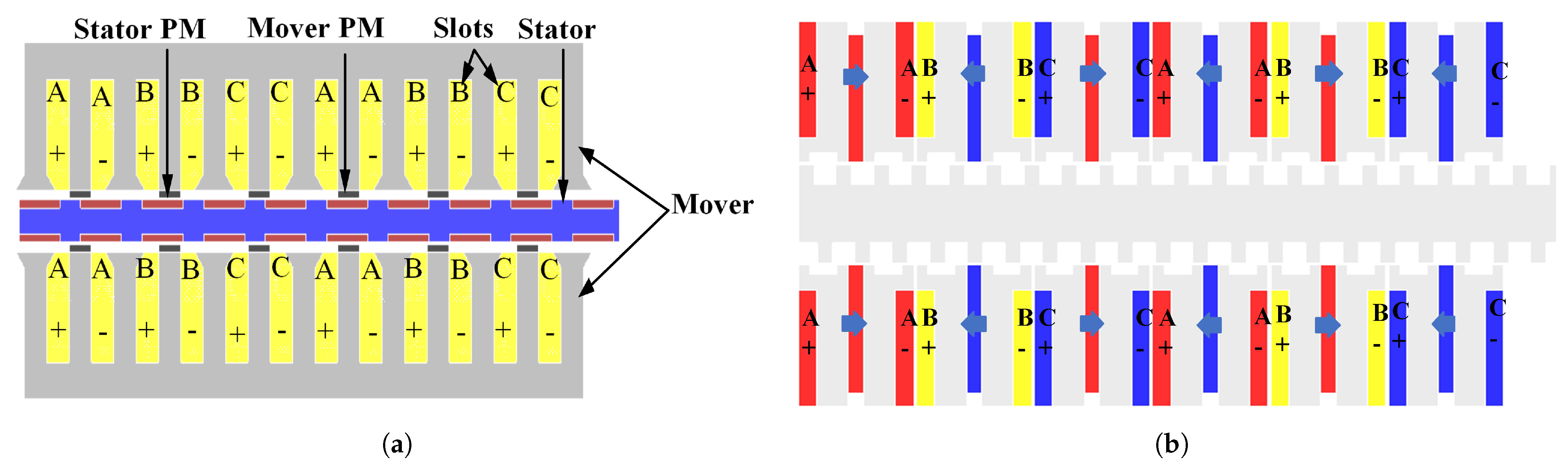
2. Topology and Operation Principle

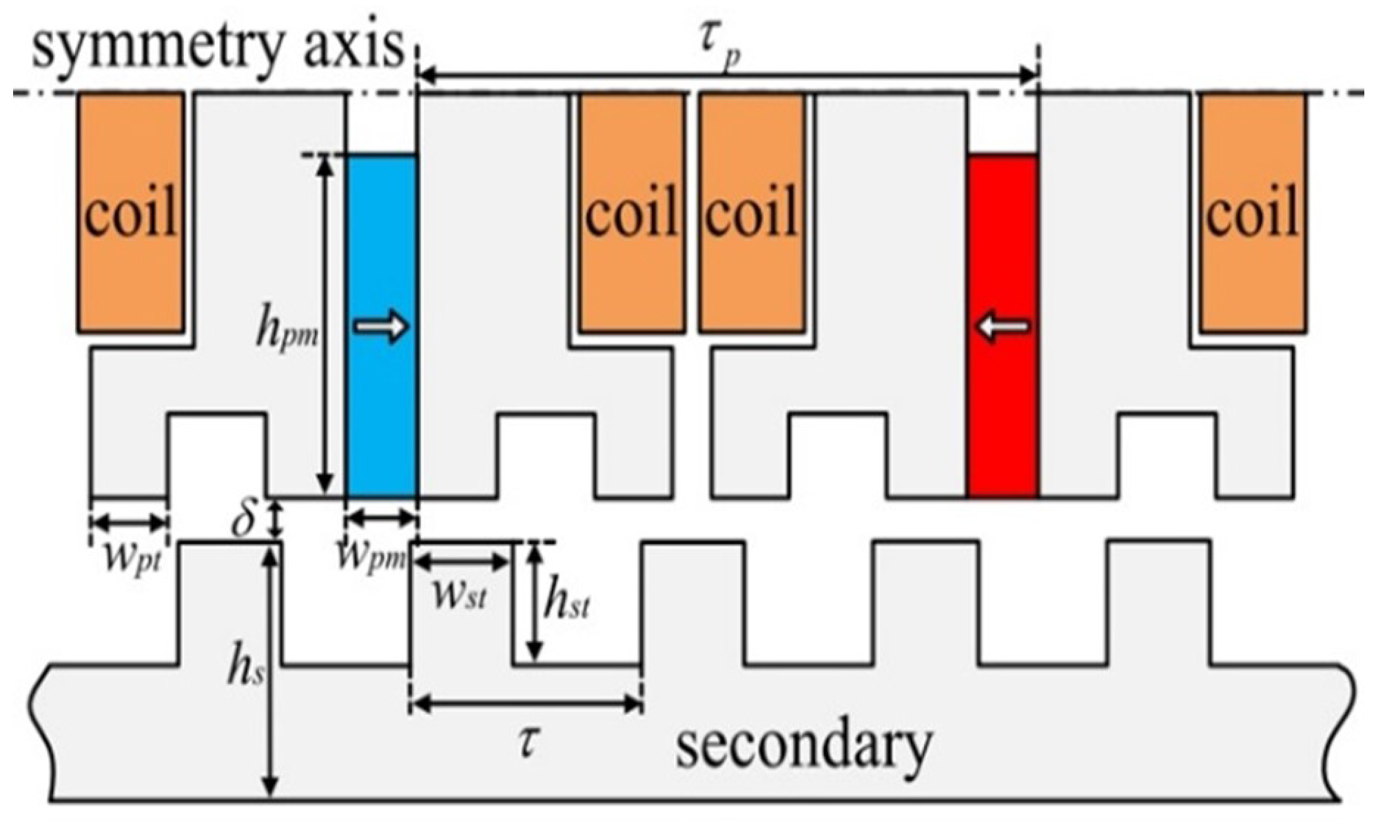
2.1. Configuration and Design Parameters

Figure 1 shows the conventional dual PM linear machine configurations and proposed dual mover yokeless multi-tooth PMFSM machines. The figure illustrates that the proposed structure consists of two movers and a stator. Its stator is sandwiched by the two movers, while the excitation sources are placed on the mover making it suitable for ropeless application. The direction of current should be either opposite or a half phase shift, and the same current direction should be given to produce the trust in same direction [16]. The important design parameters are shown in Figure 2. Table 1 illustrates the conventional dual PM linear machine’s detail design data and proposed dual mover yokeless multi-tooth PMFSM machine. For a fair comparison, the design parameters of both machines are kept the same.

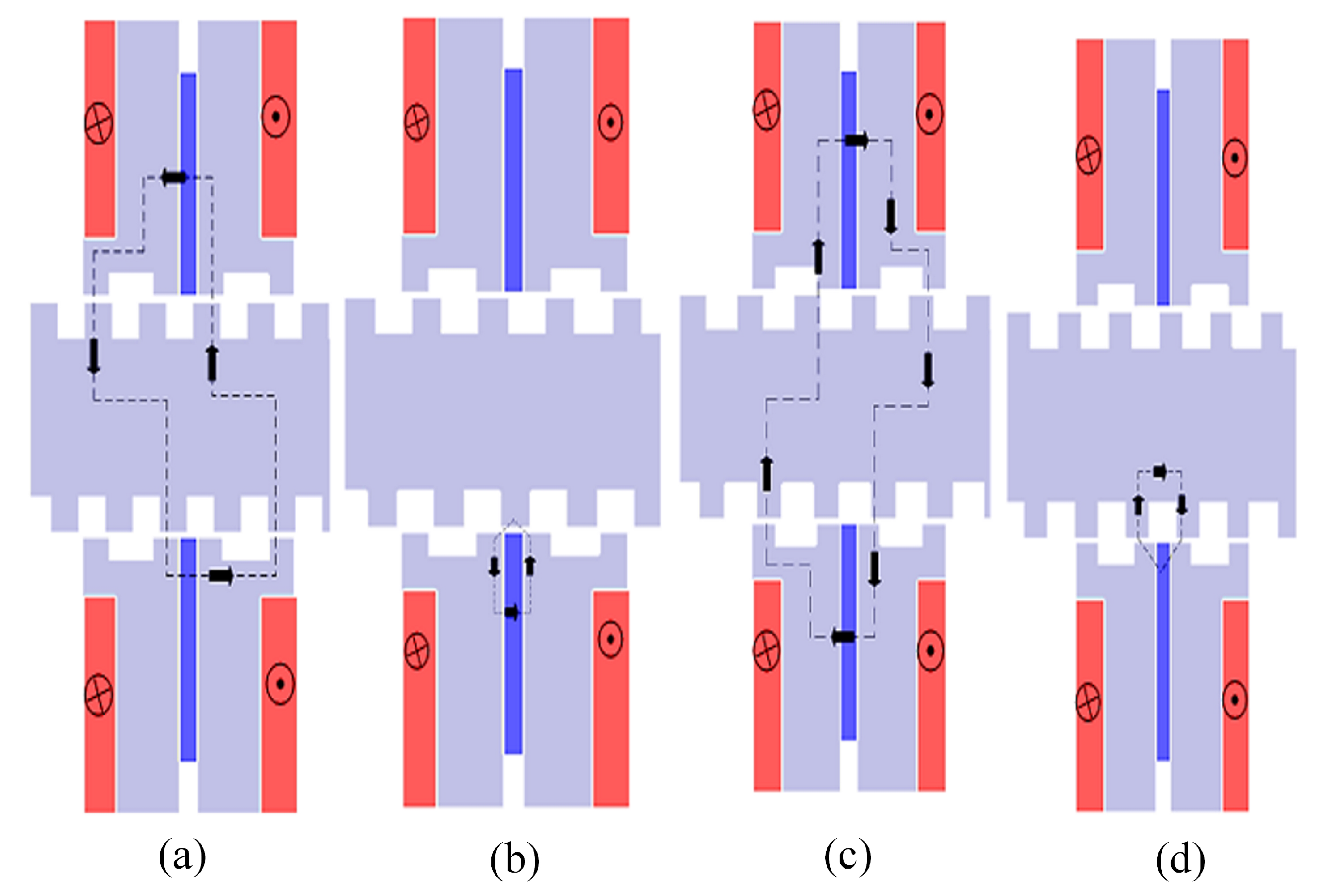
2.2. Operation Principle

The operating principle of the proposed dual mover yokeless multi-tooth PMFSM is shown in Figure 3. Like conventional permanent magnet FSM, the coil flux of the proposed dual mover yokeless multi-tooth PMFSM machine changed periodically at different mover position. At position 1, coil flux linkage reaches a maximum positive value, which shows that the flux of the upper and lower PMs is in series. When the mover translates 1 4 of the pole pitch, the coil flux linkage tends to be zero. After another one-quarter pole pitch movement of the mover, the coil flux reaches a negative maximum. When the translator moves further 1 4 of the pole pitch, again, the coil flux approaches zero. The result illustrates that the armature coil’s flux linkage is bipolar, symmetrical, and complimentary for one pole pitch movement of the mover.

3. Performance Analysis of Initial Design

The size of the coil relates to the size of wire and its placement in the slot. Therefore, it is precisely calculated by using the formula of armature current density: = N I S α , where N, I, S, and α represent the number of turns, armature current, slot area, and slot filling factor, respectively. The optimization is done while keeping the slot area constant. Initially, the performance of the proposed dual mover yokeless multi-tooth PMFSM is analyzed. The no-load flux linkage, detent force, and thrust force are shown in Figure 4. The detent force of the proposed machine is shown in Figure 4b. The peak-to-peak of the detent force is 3.5 N. The force ripples ratio is calculated as F o r c e m a x F o r c e m i n F o r c e a v g . As it is the ratio of same quantity, the force ripple ratio is unitless. Figure 4c shows that the thrust ripples are too high, i.e., 84%. Thrust ripple and detent force are essential performance parameters that affect the overall performance of the machine. Thus, for thrust ripples and detent force reduction force for the proposed design, the method of single variable optimization is adopted. Despite the detent force, both the flux linkage and thrust force profile are periodic; however, detent force is not periodic due to the dominant end effect of both movers. Note that this can be curtailed using additional end-tooth or end compensation winding.

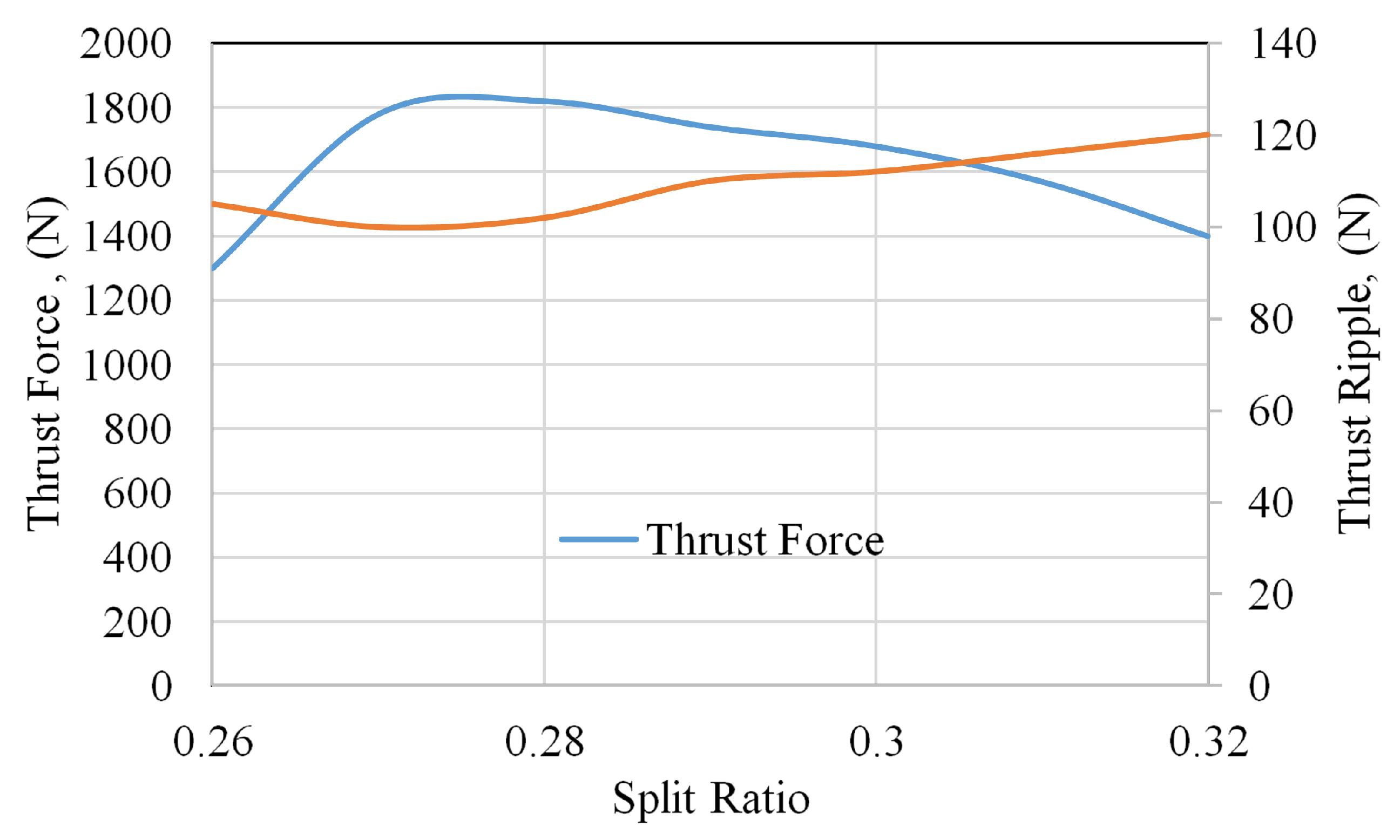
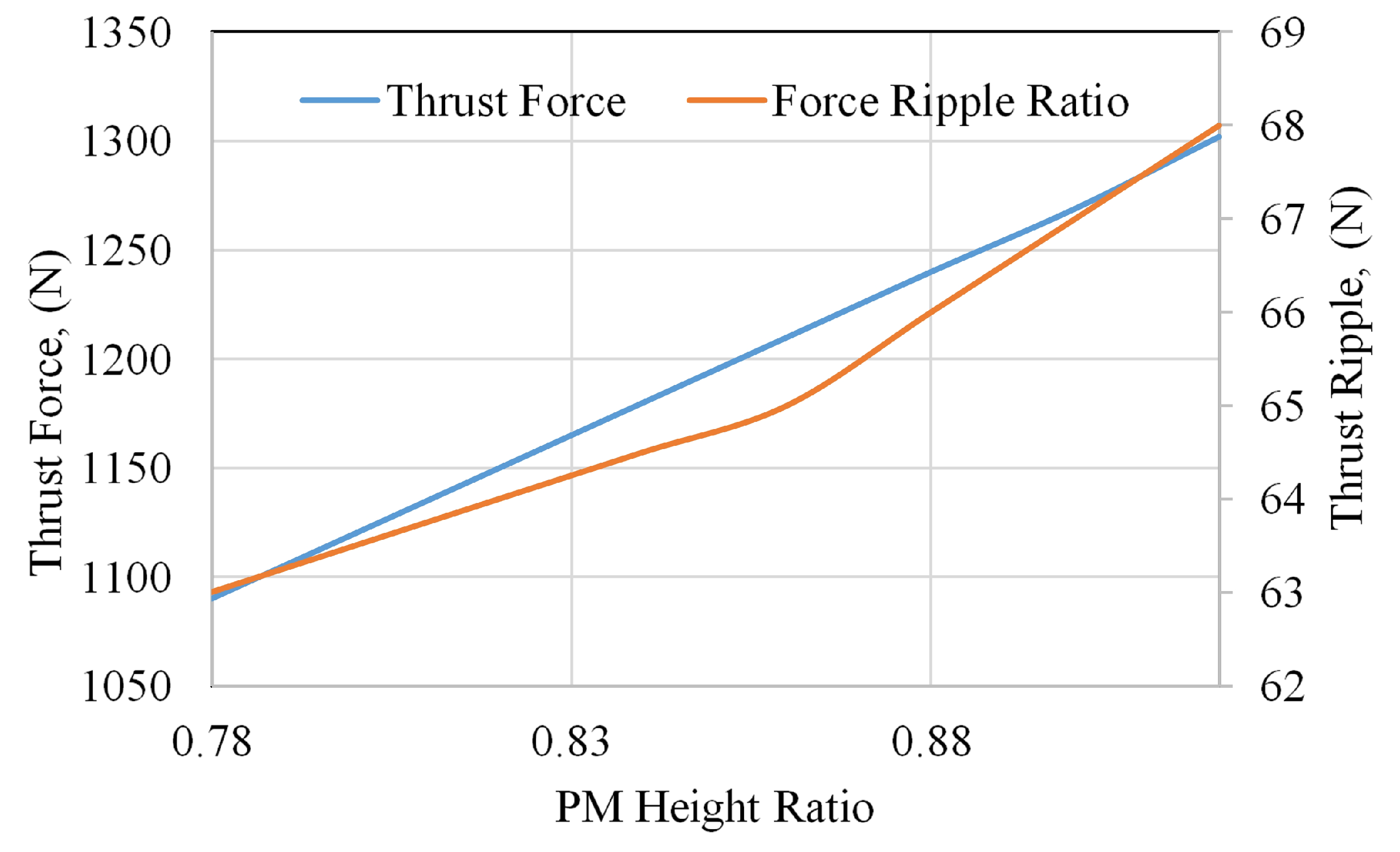
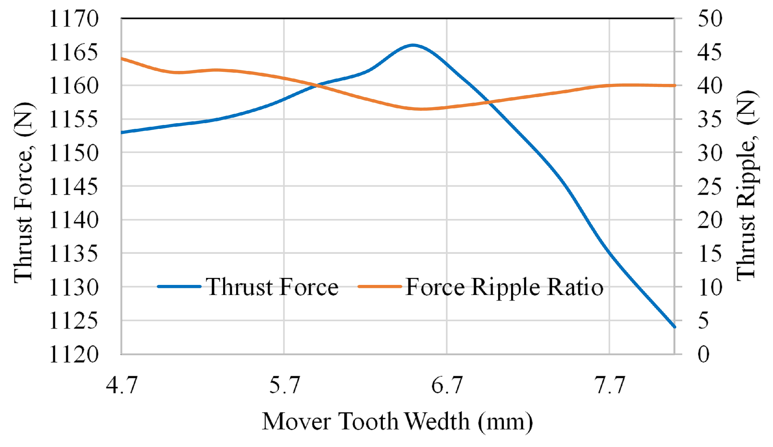
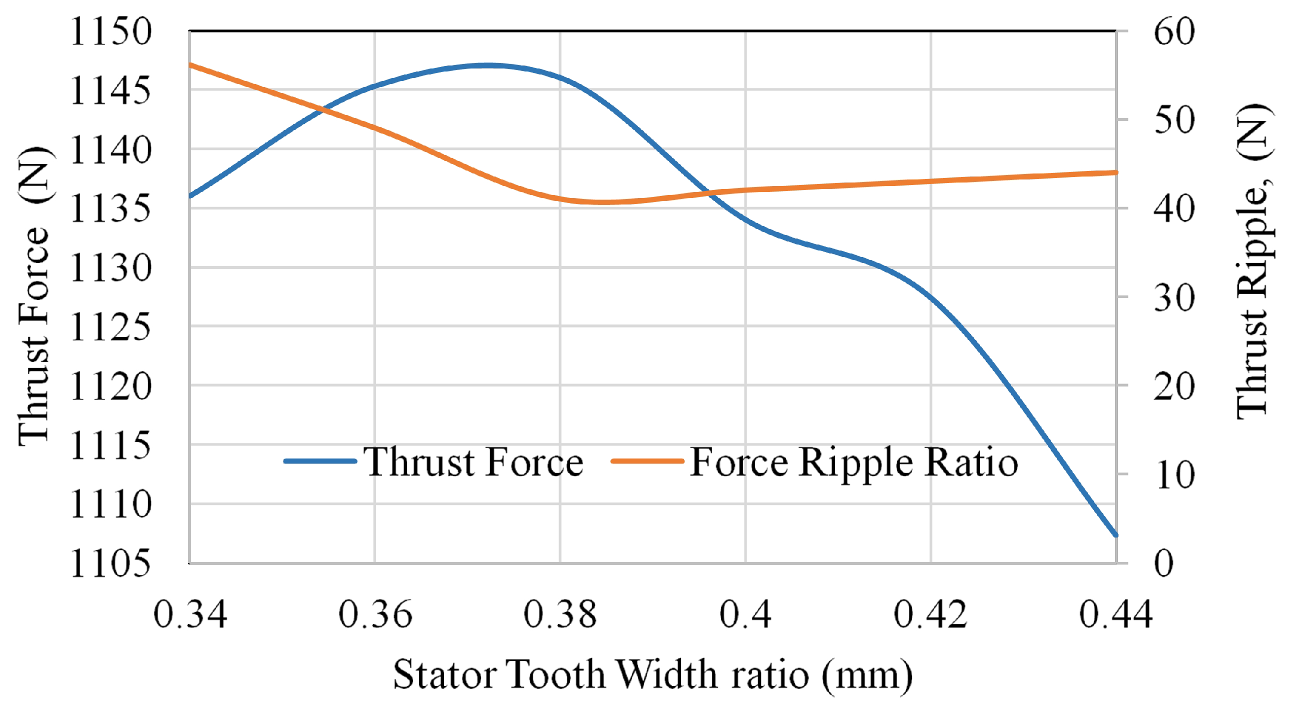
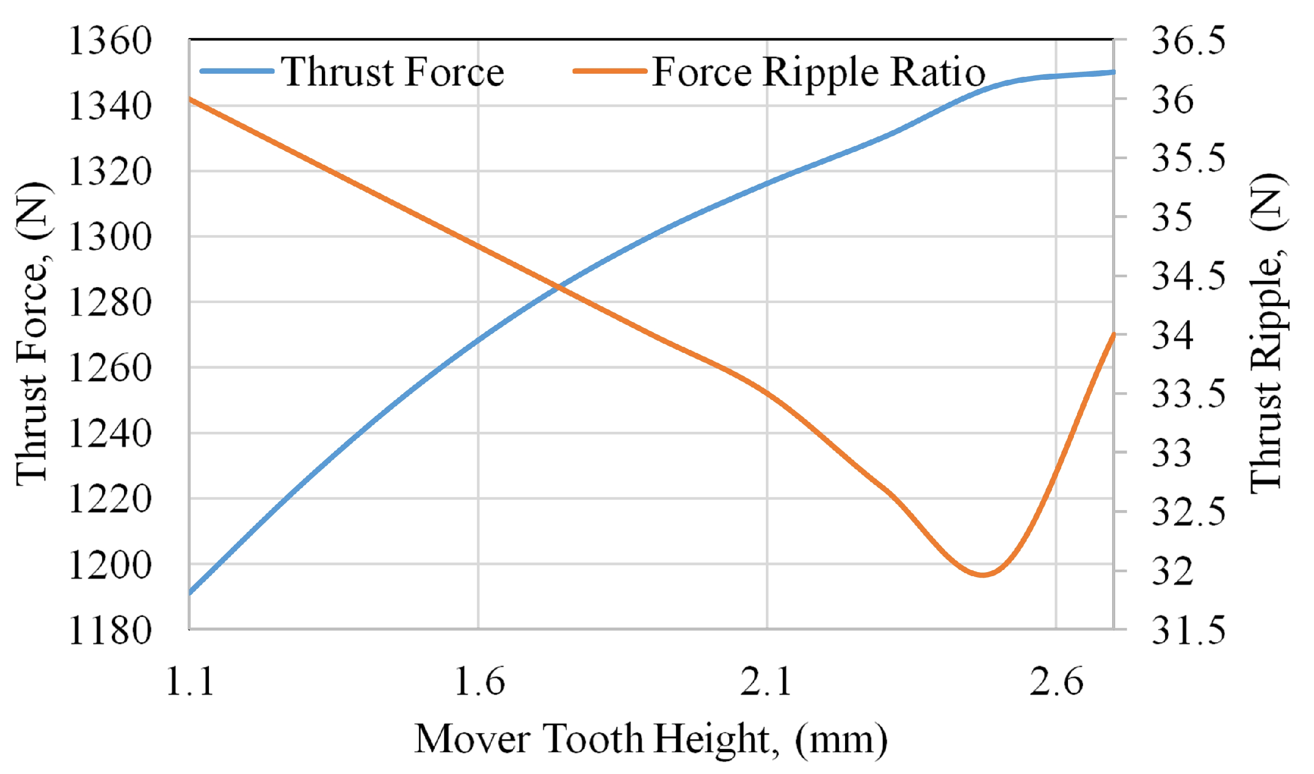
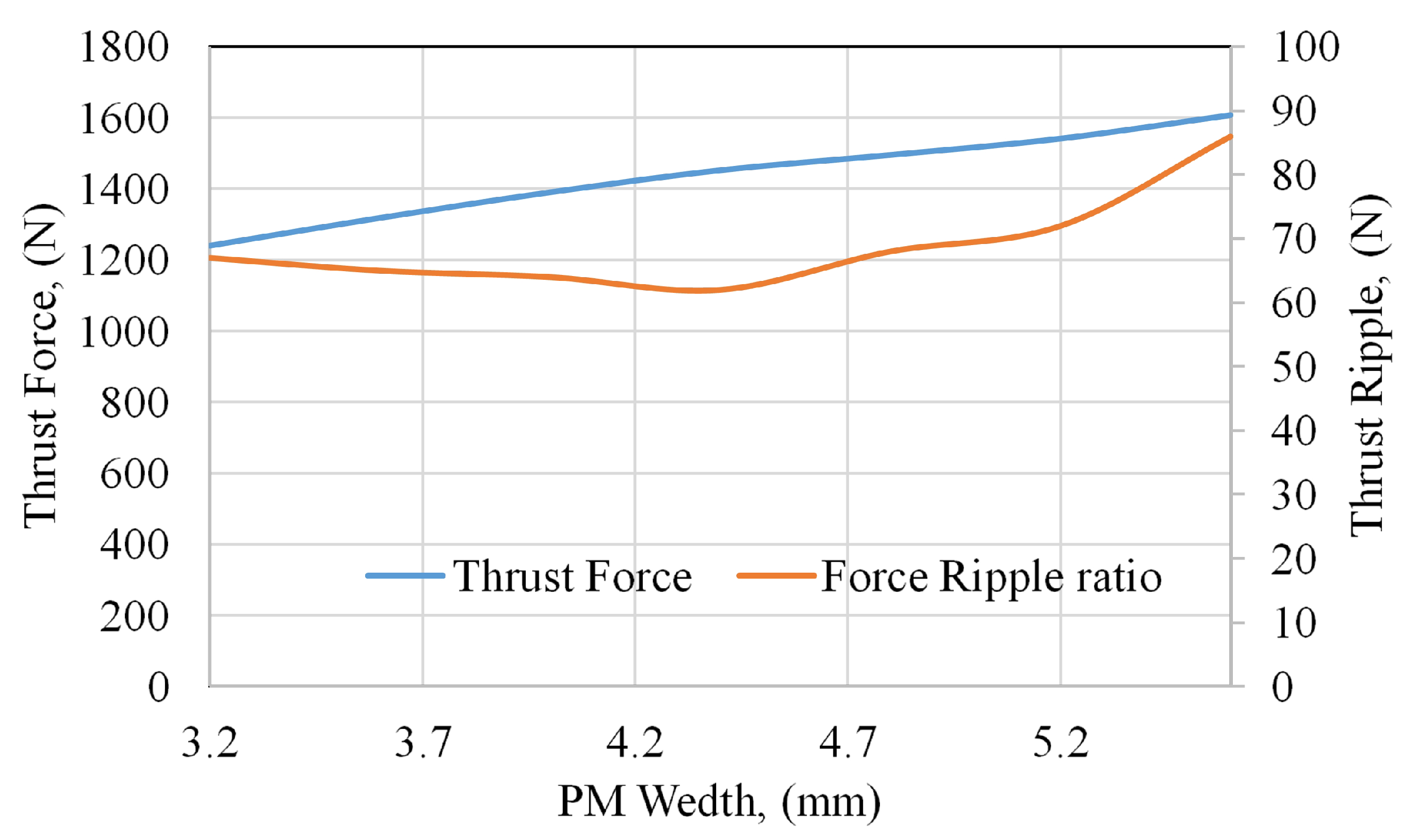
4. Single Variable Optimization for the Proposed Design

To improve the detent force and thrust ripple of dual mover yokeless multi-tooth PMFSM, the proposed design optimization is the most effective. The performance of the machines depends on several factors, such as the machine’s split ratio, tooth width of stator and mover, PM width, and height. Therefore, these parameters are optimized to reduce both detent force and thrust ripple. In order to optimize the proposed structure, single-variable optimization is adopted. For dual mover yokeless multi-tooth PMFSM, the split ratio Sr, the PMs width Wpm, the PMs height Hpm, the primary tooth width Wpt, the secondary tooth width Wst, the secondary tooth height Hst, and the primary tooth height Hpt are optimized individually. The initial values of the proposed structure are given in Table 2. The influence of split ratio on the thrust force is given in Figure 5. The split ratio for the proposed structure is calculated as
S r = h s + 2 δ h
where h , δ , and h s are the height of motor, airgap length, and stator height, respectively. Figure 5 illustrates that the optimal value of split ratio is 0.27, at which average the thrust force is maximum and thrust ripples are minimum.
H p m = h p m h p
where h p m and h p are PM height and primary height, respectively. The influence of PM height ratio on thrust force and thrust ripple is illustrated in Figure 6. The optimal value of the PM height ratio is 0.85, at which the thrust force is maximum, while the thrust ripple is minimum. The effects of mover tooth and stator tooth width on the thrust force and thrust ripple are illustrated in Figure 7 and Figure 8, respectively. Results show that the performance of the proposed structure is sensitive to both mover and stator tooth width. The optimal values of mover and stator tooth width are 6.4 and 0.38, respectively. Figure 9 illustrates the variation of thrust force and thrust ripple with mover tooth height. The optimal value of mover tooth height is 2.45, at which thrust ripple is minimum, while thrust force is maximum. The influence of PMs width is illustrated in Figure 10. The figure illustrates that the optimal PM width value is 4.3 mm, at which the thrust ripple is low, while the thrust force is high. The optimal values of the design parameters obtained after parametric optimization are listed in Table 2. The optimal values of the detent force, thrust ripple ratio, and thrust force obtained after single variable optimization are given in Table 3.

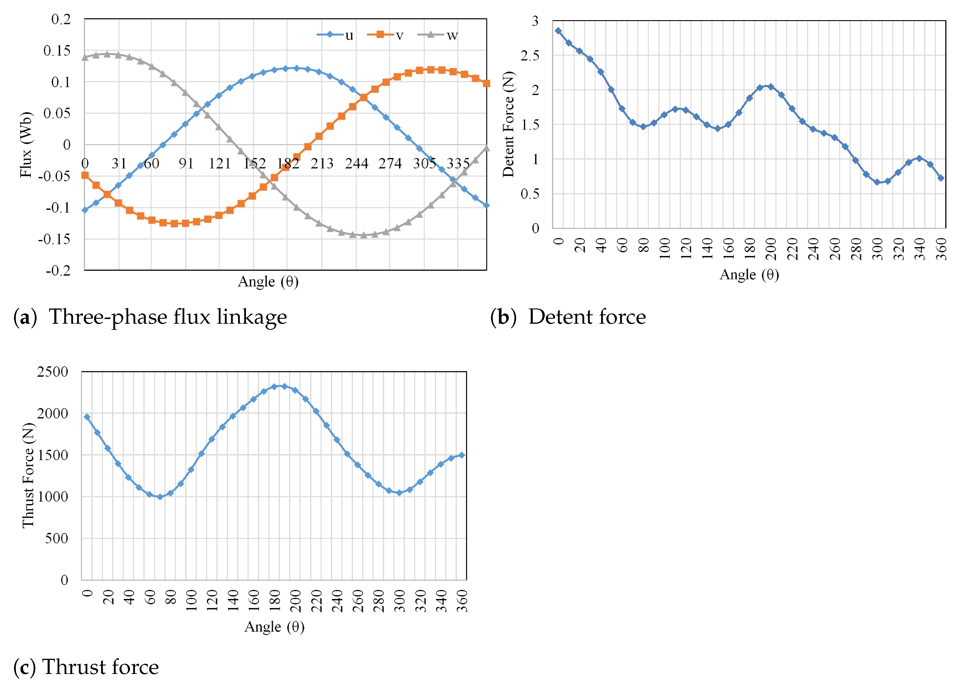
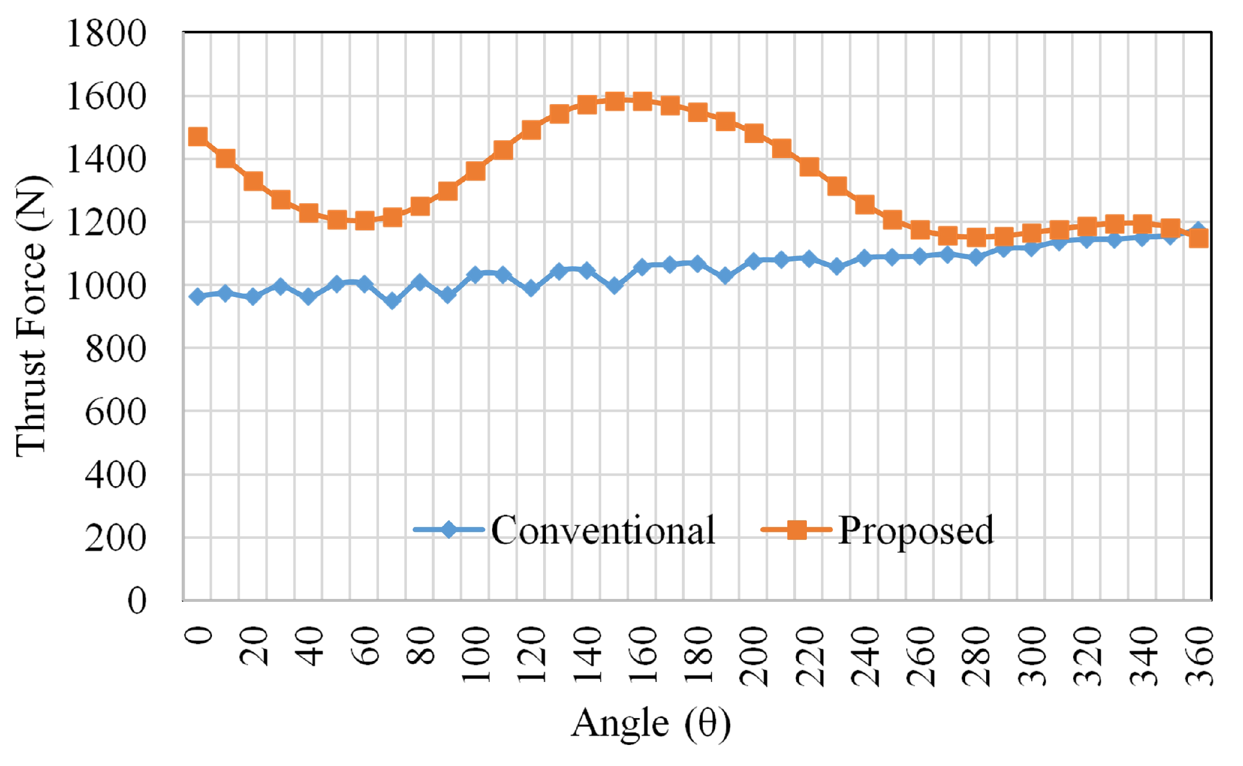
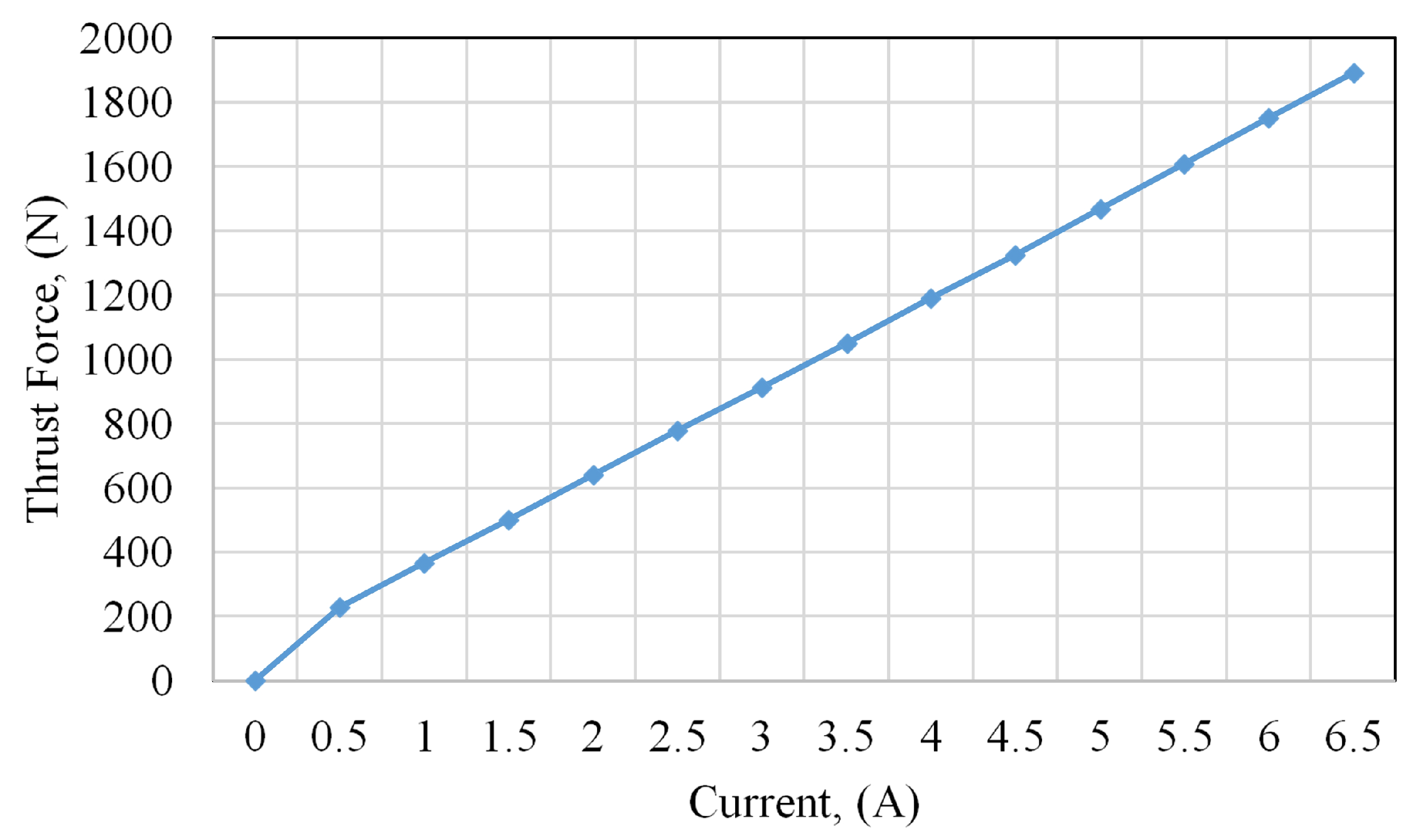
5. Electromagnetic Performance Analysis

Comparison between the thrust forces of the conventional dual PM machine and dual mover yokeless multi-tooth PMFSM proposed for the ropeless elevator are illustrated in Figure 11. The conventional design’s average thrust force is 1055 N, while that of the proposed machine is 1570 N, which is 48.81% higher than conventional. The thrust force versus current is illustrated in Figure 12.

6. Analytical Validation of Detent Force and Thrust Force

The presence of all active sources, i.e., armature windings and PMs, on the short mover and magnetic saturation of LPMFSM forces the designers to adopt a numerical method of analysis, i.e., Finite Element Analysis (FEA). An analytical approach is adopted to validate the performance parameter such as thrust force and detent force of the proposed dual mover yokeless multi-tooth PMFSM. The detent force and thrust force calculated analytically for the proposed novel dual mover yokeless multi-tooth PMFSM are assessed by comparing with the universally accepted FEA results. For analytical calculation, remanence coercivity of the PM and PM permeability considered was 1.05 and 1.2 T, respectively. The BH-curve for the iron core (35H210) is shown in Figure 13.

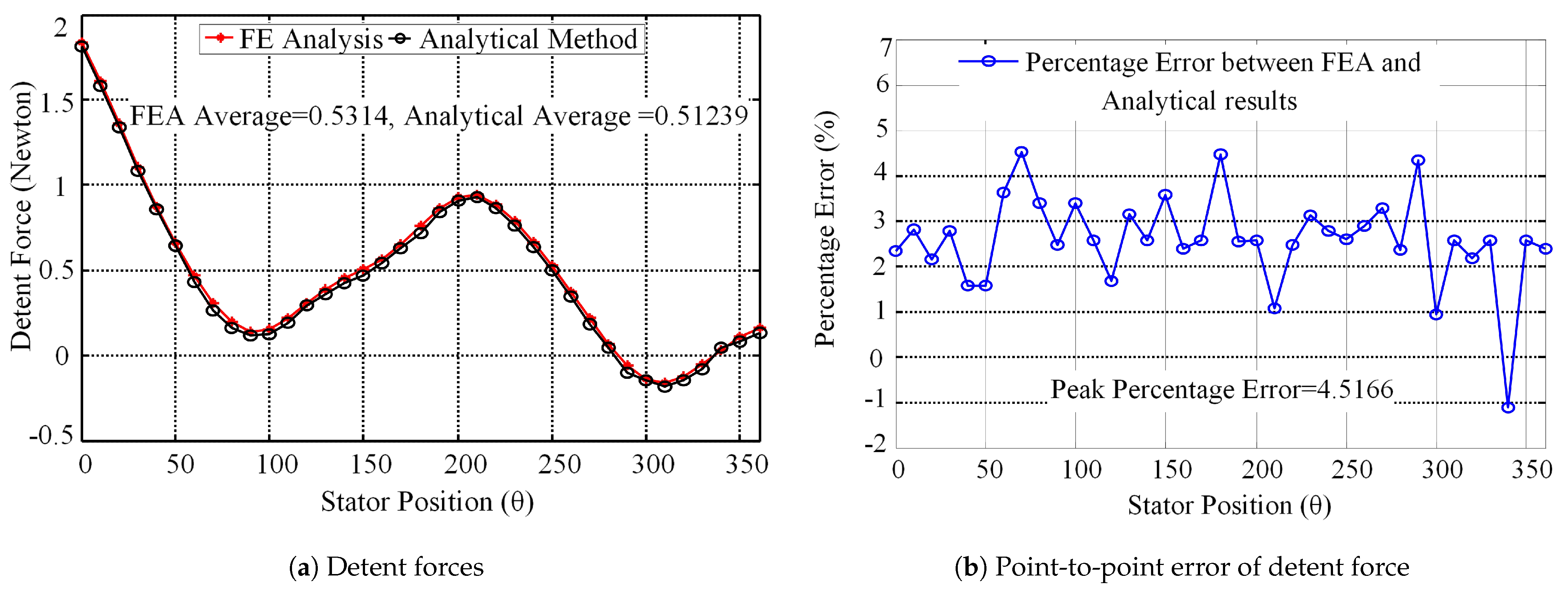
6.1. Analytical Validation of Detent Force

Detent force is an important performance parameter caused due to the end effect and interaction of PMs with stator slots. Researchers adopt different techniques to minimize the detent force, like adding auxiliary teeth at both motor ends. Some researchers adopt the harmonic injection method [9]. In this section, an appropriate and accurate tool is developed for the analysis of detent force. Detent force is calculated by the Maxwell Stress Tensor (MST) equation and can be expressed as
Fdet _ = G C D N m s , N s p L μ 0 0 L p e r B x ( x , y ) · B y ( x , y ) · d x
For validation of the proposed analytical approach, FEA results are compared with the analytical model. Figure 14 illustrates the comparison between the flux density components calculated by (3–4) and FEA results. The no-load flux density components are calculated in airgap (y = g/2) between mover and stator. The detent force of the proposed structure obtained analytically (Equation (1)) is compared with the FEA result. Comparison of the detent force obtain by FEA and analytical approach is shown in Figure 14a. The point to point error of the proposed analytical approach is shown in Figure 14b, which is less than 4.2%. Therefore, analytical prediction is validated with FEA computation.

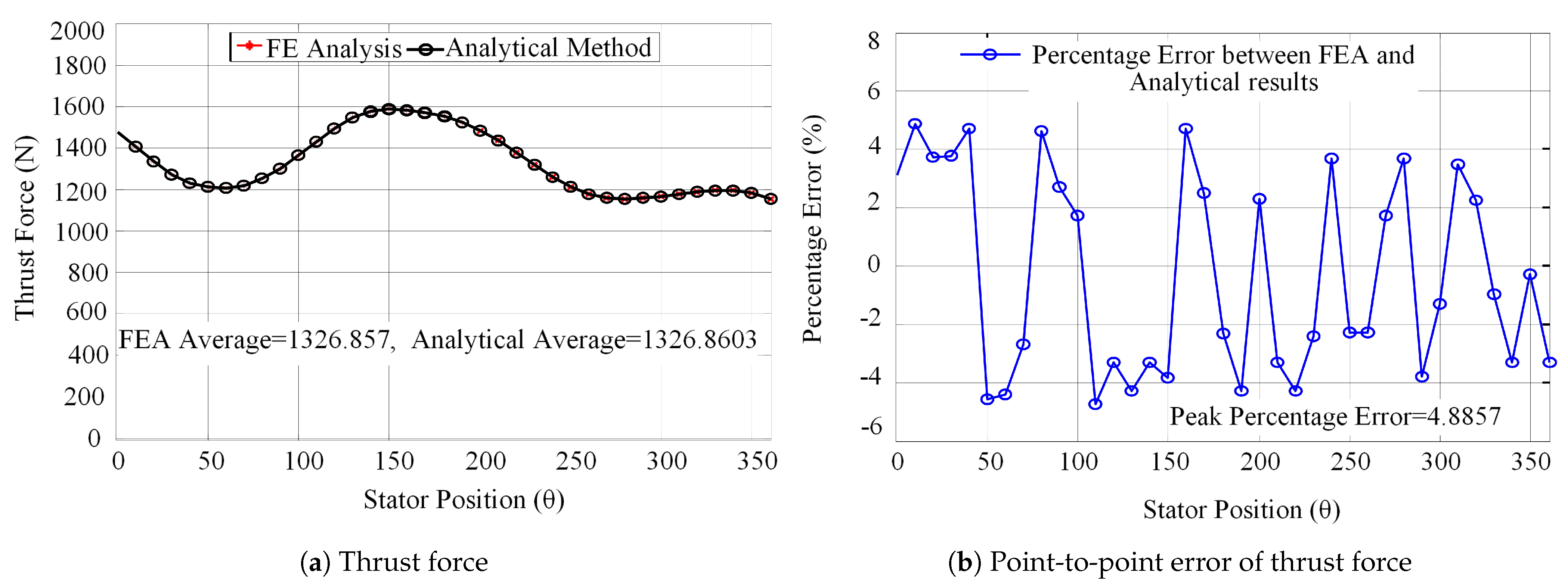
6.2. Analytical Validation of Average Thrust Force

Average thrust force is the overall thrust force developed due to mutual effect of all excitation sources, i.e., PMs and armature winding. The thrust force is derived from MST, calculated as
Fav = L a μ 0 n = 0 T B x ( x , y ) B y ( x , y ) d x
where La is the stack length μ 0 is permeability of free space. The X-component and Y-component of the flux density derived from the Laplace equation are evaluated as
Bx ( x , y ) = n = 1 4 c Q n τ sinh 2 π n y τ sin 2 π n x τ sinh 2 π n g τ By ( x , y ) = B 0 n = 1 4 c Q n τ cosh 2 π n y τ cos 2 π n x τ sinh 2 π n g τ
The parameter c as a function of average flux density B 0 can be obtained as
c = k c 1 B 0 K
Constant K is obtained as
K = n = 1 2 1 n Q n τ sinh π n g τ
The constant Q n for any positive integer is defined as
Qn = 0 w 2 1 w 2 x 3 1 w 2 3 + x sin 2 π n x τ d x
The Carters coefficient kc , as a function of the airgap width g , pole pitch τ , and slot width w is evaluated as
kc = τ w τ w w g 5 + w g
Figure 15a,b illustrates the comparison between the load flux density components calculated by (2) and (3) and FEA simulation. A comparison of the analytically obtained thrust force result and the FEA simulation is shown in Figure 16a. Results show that both the analytical and FEA results match fairly well with each other. The point to point error is shown in Figure 17b, which is less than 4.8%. Again, a good agreement is found between analytical and FEA results. The control strategy and fabrication of the proposed design will be presented as future work using robust control schemes as presented in [17].

7. Conclusions

In this paper, a dual mover yokeless multi-tooth PMFSM is proposed for ropeless elevator applications. The initial design has a high thrust ripple and detent force. To improve the thrust ripple and detent force, parametric optimization is adopted. After optimization, the thrust ripple and detent force are improved 32% and 31%, respectively. The proposed machine has a high thrust force of 1379N, that is, 79% higher than the conventional dual PM machine proposed for ropeless elevator application with low iron losses (Yokeless mover). The proposed structure has PM on the short mover that makes it cost-effective, whereas the conventional dual PM motor for ropeless elevator has a high cost, due to the existence of PM located on long stator. In the end, analytical approach is adopted to validate the FEA results. The analytical result shows a good agreement between the FEA and the analytical approach. Thus, the proposed dual mover yokeless multi-tooth PMFSM has good future applications for vertical transportation systems.

Author Contributions

Conceptualization, A.Z. and F.K.; methodology, N.A.; validation, I.S. and W.U., formal analysis, N.U. (Noman Ullah); investigation, H.I.A.; resources, writing, review A.Z.; editing, I.S. funding acquisition, N.U. (Nasim Ullah) All authors have read and agreed to the published version of the manuscript.

Funding

This research work was supported by Taif University Researchers Supporting Project number (TURSP-2020/144), Taif University, Taif, Saudi Arabia.

Institutional Review Board Statement

Not applicable.

Informed Consent Statement

Not applicable.

Data Availability Statement

No new data were created or analyzed in this study. Data sharing is not applicable to this article.

Conflicts of Interest

The authors declare no conflict of interest.

References

  1. Amara, Y.; Barakat, G. Analytical modeling of magnetic field in surface mounted permanent-magnet tubular linear machines. IEEE Trans. Magn. 2010, 46, 38703884. [Google Scholar] [CrossRef]
  2. Chen, J.T.; Zhu, Z.Q.; Howe, D. Stator and rotor pole combinations for multi-tooth flux-switching permanent-magnet brushless AC machines. IEEE Trans. Magn. 2008, 44, 4659–4667. [Google Scholar] [CrossRef]
  3. Du, Y.; Ming, C.; Chau, K.T.; Xianxing, L.; Feng, X.; Wenxiang, Z.; Kai, S.; Lihong, M. Comparison of linear primary permanent magnet vernier machine and linear vernier hybrid machine. IEEE Trans. Magn. 2014, 50, 1–4. [Google Scholar] [CrossRef] [Green Version]
  4. Fan, H.; Chau, K.T.; Chunhua, L.; Libing, C.; Ching, T.W. Quantitative Comparison of Novel Dual-PM Linear Motors for Ropeless Elevator System. IEEE Trans. Magn. 2018, 99, 1–6. [Google Scholar] [CrossRef]
  5. Gandhi, A.; Parsa, L. Thrust optimization of a flux-switching linear synchronous machine with yokeless translator. IEEE Trans. Magn. 2013, 49, 1436–1443. [Google Scholar] [CrossRef]
  6. Lee, S.G.; Sung, A.K.; Subrat, S.; Yu, W.Z.; Yun, H.C. Optimal structure design for minimizing detent force of PMLSM for a ropeless elevator. IEEE Trans. Magn. 2014, 50, 1–4. [Google Scholar] [CrossRef]
  7. Lim, H.S.; Ramu, K.; Nimal, S.L. Design and control of a linear propulsion system for an elevator using linear switched reluctance motor drives. IEEE Trans. Ind. Elect. 2008, 55, 534–542. [Google Scholar] [CrossRef]
  8. Lim, H.S.; Ramu, K. Ropeless elevator with linear switched reluctance motor drive actuation systems. IEEE Trans. Ind. Elect. 2007, 54, 2209–2218. [Google Scholar] [CrossRef]
  9. Liu, Q.; Haitao, Y.; Minqiang, H.; Chunyuan, L.; Jing, Z.; Lei, H.; Shigui, Z. Cogging force reduction of double-sided linear flux-switching permanent magnet machine for direct drives. IEEE Trans. Magn. 2013, 49, 2275–2278. [Google Scholar] [CrossRef]
  10. Liu, C.; Chau, K.T.; Wenlong, L. Comparison of fault-tolerant operations for permanent-magnet hybrid brushless motor drive. IEEE Trans. Magn. 2010, 46, 1378–1381. [Google Scholar] [CrossRef]
  11. Lobo, N.S.; Hong, L.; Krishnan, R. Comparison of linear switched reluctance machines for vertical propulsion application: Analysis, design, and experimental correlation. IEEE Trans. Ind. Appl. 2008, 44, 1134–1142. [Google Scholar] [CrossRef]
  12. Lu, Q.; Li, H.; Huang, X.; Ye, Y. Research on yokeless double-sided multi-tooth flux-switching linear motor. Int. J. Comput. Math. Elect. Electron. Eng. COMPEL 2016, 35, 832–843. [Google Scholar] [CrossRef]
  13. Onat, A.; Kazan, E.; Takahashi, N.; Miyagi, D.; Komatsu, Y.; Markon, S. Design and implementation of a linear motor for multicar elevators. IEEE/ASME Trans. Mechatronics 2010, 15, 685–693. [Google Scholar] [CrossRef] [Green Version]
  14. Wang, C.F.; Jian, X.S.; Yu, W.; Li, L.W.; Meng, J.J. A new method for reduction of detent force in permanent magnet flux-switching linear motors. IEEE Trans. Magn. 2009, 45, 2843–2846. [Google Scholar] [CrossRef]
  15. Yiming, S.; Lu, Q.; Li, H.; Cai, J.; Huang, X.; Fang, Y. Analysis of a Novel Double-Sided Yokeless Multitooth Linear Switched-Flux PM Motor. IEEE Trans. Ind. Elect. 2018, 65, 1837–1845. [Google Scholar] [CrossRef]
  16. Zhang, B.; Ming, C.; Sa, Z.; Mingli, Z.; Wei, H.; Ruiwu, C. Investigation of linear flux-switching permanent magnet machine for ropeless elevator. In Proceedings of the IEEE 19th International Conference Electrical Machines and Systems (ICEMS), Chiba, Japan, 13–16 November 2016; pp. 1–5. [Google Scholar]
  17. Sami, I.; Ullah, S.; Ali, Z.; Ullah, N.; Ro, J.-S. A Super Twisting Fractional Order Terminal Sliding Mode Control for DFIG-Based Wind Energy Conversion System. Energies 2020, 13, 2158. [Google Scholar] [CrossRef]
Figure 1. Nominal case: (a) Conventional dual permanent magnet (PM) machine for ropeless elevator applications. (b) Proposed dual mover yokeless multi-tooth PMFSM for ropeless elevator applications.
Actuators 10 00081 g001
Figure 2. Structure and parameters of the proposed dual mover yokeless multi-tooth PMFSM.
Actuators 10 00081 g002
Figure 3. (a) Position 1, (b) Position 2, (c) Position 3, (d) Position 4.
Actuators 10 00081 g003
Figure 4. Initial design performance analysis.
Actuators 10 00081 g004
Figure 5. Variation of thrust force and thrust ripple for a novel dual mover yokeless multi-tooth PMFSM.
Actuators 10 00081 g005
Figure 6. Force ripple and thrust force variation with PM height ratio for dual mover yokeless multi-tooth.
Actuators 10 00081 g006
Figure 7. Force ripple and thrust force variation with mover tooth width for dual mover yokeless multi-tooth PMFSM.
Actuators 10 00081 g007
Figure 8. Force ripple and thrust force variation with stator tooth width for dual mover yokeless multi-tooth PMFSM.
Actuators 10 00081 g008
Figure 9. Force ripple and thrust force variation with mover tooth height for PMFSM.
Actuators 10 00081 g009
Figure 10. Variation of thrust ripples and thrust force with PM width for dual mover yokeless multi-tooth PMFSM.
Actuators 10 00081 g010
Figure 11. Comparison of thrust force for the conventional and proposed machine for ropeless elevator application.
Actuators 10 00081 g011
Figure 12. Thrust force verses q-axis current.
Actuators 10 00081 g012
Figure 13. BH curve of 35H210 silicon steel sheet.
Actuators 10 00081 g013
Figure 14. No-Load flux density comparison at y = g/2 (Air gap).
Actuators 10 00081 g014
Figure 15. FE and analytical method comparison for Detent forces.
Actuators 10 00081 g015
Figure 16. On-Load Comparison of load flux density at y = g/2 (Airgap).
Actuators 10 00081 g016
Figure 17. Comparison of thrust force obtained by Maxwell Stress Tensor (MST) and finite element analysis (FEA).
Actuators 10 00081 g017
Table 1. Design parameters.
ParametersConventionalProposed
Np1212
Primary slot pitch, Tp (mm)26.250.4
Motor Height, h9393
air gap length (mm)1.51.5
Stack length, L (mm)200200
Wire size (mm)0.80.8
Number of turns200200
PM Height337.5
PM width, Wpm (mm)13.13.2
Primary Tooth width, Wpt (mm)2.22.2
Mover length, (mm)300300
Average Speed (m/s)11
Current (A)4.54.5
Table 2. Design parameters before and after optimization.
ParametersInitial ValuesOptimal Values
Split Ratio0.310.27
PM Height ratio0.780.85
Stator tooth width ratio0.340.375
Mover tooth width (mm)4.76.5
PM width (mm)5.64.3
Mover tooth height (mm)1.72.5
Table 3. Performance analysis before and after parametric optimization.
Performance ParametersInitial ValuesOptimal Values
Detent Force ( N ) 1.60.5
Thrust Force ( N ) 15701326
Thrust Ripple Ratio ( % ) 84.432.5
Publisher’s Note: MDPI stays neutral with regard to jurisdictional claims in published maps and institutional affiliations.

