Abstract
In high-end testing and manufacturing equipment, a trend exists whereby the traditional servo feed system with a ball screw and rotary motor will gradually be replaced by a direct drive system. The precision motion system driven by a permanent magnet linear synchronous motor (PMLSM) offers several advantages, including high speed, high acceleration, and high positioning accuracy. However, the operating precision of the feed device will be affected by the PMLSM robustness to nonlinear and uncertain disturbances, such as cogging force, friction, thermal effects, residual vibration, and load disturbance. The aim of this paper was to provide a survey on disturbance analysis and suppression approaches to improve the dynamic performance of PMLSM motion systems. First, the origin and inhibition methods of thrust ripple and friction are presented. Second, the mechanisms, modeling approaches, and mitigation measures of thermal effects are introduced. Additionally, the residual vibration characteristics and suppression methods are discussed. Finally, disturbance observers of periodic and aperiodic loads are introduced. These suppression methods from structural design and control compensation are then discussed in order to improve the dynamic response and steady-state accuracy of PMLSM.
1. Introduction
High-speed and high-precision feed devices, such as detection platforms, machine tools, precision operating systems, and automatic assembly machines, are undergoing rapid development owing to the pressing needs for high productivity and high-precision measurement and manufacturing [1]. Traditional linear motion systems use rotary motors and ball screws to achieve linear motion, but the performance of such a feed drive system is limited by the rotation speed, inertia, backlash, and hysteresis [2]. A feed system driven by a permanent magnet linear synchronous motor (PMLSM), without intermediate mechanical transmission components, offers numerous advantages in dynamic performance and positioning accuracy.
Accordingly, considering the elimination of intermediate transmission structures, PMLSMs also exhibit some difficulties in structure optimization and controller design to achieve the performance of high speed/precision [3,4,5,6]. A PMLSM is a typical nonlinear coupling system, and therefore, the motion accuracy is subject to adverse factors such as thrust force ripple, friction, thermal effects, residual vibrations, and load disturbances. These effects cannot be weakened by an intermediate structure but act on the mover directly. The stability and dynamic characteristics of linear feed devices would be affected, and thus, the operating precision of the system would be degraded.
Thrust ripple and friction are two major nonlinear disturbances acting upon PMLSMs, affecting the dynamic characteristics and inducing vibrations [7,8]. In terms of thrust ripple, it is position-determined and affected by the slot–pole combination. Two main weakening techniques of this ripple are motor structure optimization and force ripple compensation [9]. Friction is a typical disturbance which is dependent on the operating speed. It is necessary to analyze the mechanisms and adjust methods in consideration of the working conditions.
The rapid temperature rise in PMLSMs is usually caused by massive power loss, as a high current density is required for such a direct drive system to achieve large thrust and high speed. The temperature rise in a PMLSM may lead to thermal errors and even demagnetization and winding insulation failure [10,11]. Even with a cooling system, local temperature rise is still inevitable, which will cause parameter variations of the PMLSM and degrade the dynamic performance. Thus, it is essential to investigate the thermal behavior of linear motors and design a controller to compensate for the influence induced by heat.
PMLSMs are characterized by low damping owing to the lack of an intermediate transmission mechanism and, therefore, easily cause transient vibrations [4,12]. With an unsuitable trajectory, the saltation of velocity leads to discontinuities in acceleration and exhibition of infinite jerk [1]. Combined with the requirement of high stiffness, a high regulator coefficient of a controller will make the output of the controller change drastically, thereby causing PMLSM overshoot and residual variation. In order to improve the dynamic performance and positional accuracy, some research studies proposed trajectory planning algorithms, feed-forward and feedback control strategies, and external dampers to improve the PMLSM’s performance.
Load disturbances are directly applied on the mover of a PMLSM and deteriorate the accuracy. Cable force and machine cutting force are common load disturbances in PMLSM motion systems [13]. Generally, load disturbances are difficult to model due to the nonlinear and time-varying characteristics [14]. To suppress load disturbances, in one study, researchers applied a modeless vibration suppression method on a PMLSM motion system [4]. In another method, researchers traced the source and the formation of the load disturbances and then built mathematical models such as a cutting force model, a chatting prediction model, and an electromechanical coupling effect model [15,16,17].
The remainder of this paper is organized as follows: Section 2 introduces the suppression approaches of thrust ripple and friction. Section 3 presents the modeling of thermal behavior, thermal management techniques, and compensation methods. In Section 4, trajectory planning, feed-forward and feedback control, and dampers for weakening the residual vibration are introduced. The basic control scheme and suppressing methods of load disturbances are analyzed in Section 5.
2. Thrust Ripple and Friction
Different from rotary motors, disturbances consisting of thrust ripple and friction decrease the PMLSM system performance directly [18,19] due to the elimination of mechanical transmission [20]. The worst result is that these force ripples excite the mechanical resonances at a special velocity [7]. Therefore, studying the compensation of thrust ripple and friction is vital for PMLSMs. In this section, firstly, the causes of force ripple in PMLSMs are introduced. Then, the motor structure analysis and parameters’ optimization for reducing force ripple are presented. Lastly, the compensation strategies in control systems are compared and discussed.
2.1. Causes of Force Ripple and Friction
The disturbances in PMLSMs are caused by different aspects, including detent force, the harmonics of back-electric motive force (EMF), and driving current.
Compared with that of rotary motors, the end effect force and cogging force of the PMLSM constitute the detent force, and they are the major components of thrust ripple [21]. The detent force is periodic [22] and is only determined by the relative position between the stator and the mover of a motor [23]. It is noted that the force ripple is an electromagnetic effect, which is related to the magnetic field and the phase currents. Moreover, the variations in the magnetic flux density are amplified by the motor magnetic saturation and stator-winding resistance variations [24].
Meanwhile, the current contains harmonic components, which will result in an inaccurate back-EMF model and produce thrust ripple as well [25]. Some structural design methods such as skewing [21,26], segmentation of a magnet [27], and optimization of the magnet pole arc coefficient [28] can effectively suppress the detent force and current harmonics. In terms of system control, approaches such as the dead-time elimination method for a pulse width modulation (PWM)-controlled inverter/converter [29], harmonic injection [30], and adding a resonant controller [31] are proposed to reduce the current harmonics. Simultaneously, friction is velocity-dependent and nonlinear [32], which is non-Lipschitz in the initial state [33]. The disturbances mentioned above will largely degrade the performance of PMLSM systems.
Numerous studies have attempted to compensate for thrust ripple and friction using two methods: structural optimization methods and control compensation strategy [34,35,36].
2.2. Structural Optimization Methods
To date, structural optimization approaches have generally been divided into two types. The first approach is to adjust the size of some critical structures, including modifying the shape of the permanent magnet (PM) [37,38,39,40], installing an auxiliary structure [41], optimizing the length of the stator [34], using fraction slots [36], and adjusting the slot/plot combinations [36], which are promising for reducing detent force.
For instance, the detent force caused by the longitudinal end effects in PMLSMs is analyzed and minimized in [41]. First, the left/right-end forces are calculated according to an analytical model. Then, the optimal length of the primary iron is obtained based on the phase difference of the left/right-end forces and a two-step iteration. Furthermore, step-skewed auxiliary irons are added to the primary end to eliminate the second-order harmonics and reduce other high-order harmonics as shown in Figure 1. Finally, some mirror PMs are added to the ends of the secondary back iron as illustrated in Figure 2, and the resultant radial flux density is shown in Figure 3. It can be seen that adding a mirror PM is even more effective in reducing the secondary end effect compared to the results of other methods.
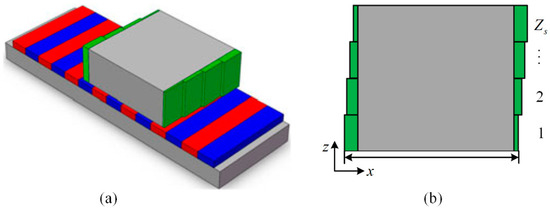
Figure 1.
Installation of auxiliary structure. (a) Three-dimensional view; (b) two-dimensional view. Reprinted with permission from ref. [41]. Copyright 2018 IEEE.
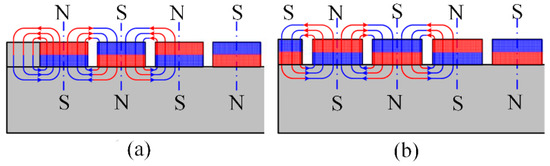
Figure 2.
Minimization of the secondary end effect. (a) Adding an iron block; (b) adding a mirror permanent magnet (PM). Reprinted with permission from ref. [41]. Copyright 2018 IEEE.
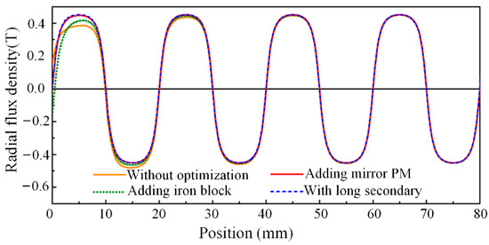
Figure 3.
Waveforms of radial flux density with different optimization methods. Reprinted with permission from ref. [41]. Copyright 2018 IEEE
Double-sided designs are popular for minimizing the detent force of PMLSMs [42]. For example, a double-sided long-stator-type PMLSM is presented in [43], as illustrated in Figure 4. The stator is made up of two groups of semi-closed slot iron core, and the concentrated windings are facing each other. The mover side is composed of two groups of permanent magnets mounted on the iron yoke surface. The results show that the structure of the 9-slot/8-pole fractional slot pitch can reduce not only the back-EMF harmonics but also the amplitude of detent force. It was proven that the fractional slot winding structure can effectively suppress the thrust fluctuation of the PMLSM in [36].
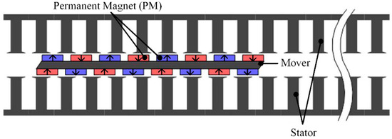
Figure 4.
Structure of a double-sided long-stator-type permanent magnet linear synchronous motor (PMLSM). Reprinted with permission from ref. [43]. Copyright 2014 IEEE.
The method of utilizing of step-skewed magnets for thrust ripple reduction is widely used in PMLSM systems [44,45]. As illustrated in Figure 5 [21], skewed PMs with an optimal skewing length are designed to compensate for detent force. The key innovation of the proposed PMLSM is that a skewed structure, as shown in Figure 6, is applied to decrease several high-order harmonics; thus, the sine wave distortion rate of the motor detent force is suppressed. The 2D finite element method (FEM) results show that the fourth-, sixth-, and eight-order harmonics of the optimal skewed PM structure are 55.7%, 93%, and 79.5% lower than those of the rectangular PMs, respectively. In comparison to the traditional structural optimization approaches, the method of reducing the high-frequency components rather than the amplitude of the detent force is more convenient and suitable for the control system to realize the minimal ripple.
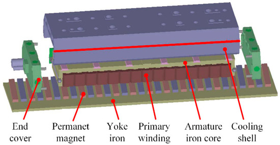
Figure 5.
Structure diagram of the proposed PMLSM with skewed PMs. Reprinted with permission from ref. [43]. Copyright 2015 IEEE
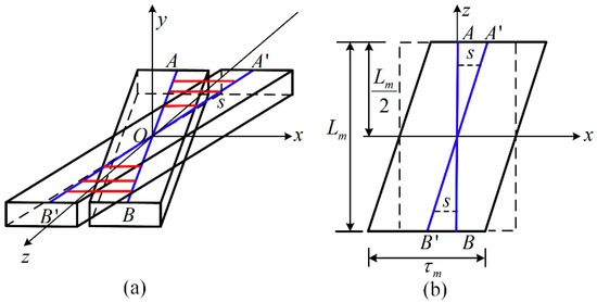
Figure 6.
(a) Three-dimensional view of the skewed PM; (b) view of the skewed PM in the y-direction. Reprinted with permission from ref. [43]. Copyright 2015 IEEE.
Furthermore, the peak-to-peak value of the detent force in PMLSMs is effectively weakened by changing the width of the PM [46,47]. In [48], chamfering also greatly reduced the detent force of PMLSM. All of the methods mentioned above can be classified as designing the key structure of the motor.
The second method is to establish the complete and accurate analytical model first [49]. Then, some optimization algorithms are utilized to obtain the optimal motor parameters for minimizing the thrust ripple and friction [50,51,52,53,54,55].
Concretely, the function of complex relative air gap permeance was introduced by Zarko et al. in [52], and the cogging torque was calculated by integrating the lateral forces that acted on the slot sides. However, this model can only account for the slotting effect; the end detent force that is caused by the longitudinal end effect is neglected.
In [49,50,56], Z. Q. Zhu et al. present the subdomain (SD) method to calculate the air gap field density accurately. It divides the motor model into several regular domains; then, the analytical expression is simplified. Based on Zhu’s method, an accurate analytical model for PMLSMs in 2D Cartesian coordinates was developed in [55]. By adding virtual slots and adopting relative air gap permeance, the end effect and slotting effect are taken into consideration, respectively. Thus, the flux linkage, back-EMF, and detent force are calculated via the proposed method. Both the FEM and prototype results show that the detent force is reduced by the optimization of the end teeth and slots based on the presented model.
Although the abundance of structural optimization designs can attenuate the force ripple effectively, they are frequently accompanied by complicated motor construction and high production costs. Therefore, control methods to decrease the thrust ripple and friction are being researched extensively.
2.3. Compensation Strategy in Control System
Feed-forward control plays a vital part in force ripple compensation [57], and the most common compensation strategy in PMLSM systems is harmonic cancellation by using suitable feed-forward current profiling [58]. As thrust ripple is affected by the magnetic field and phase currents, the phase currents can produce a smooth force only when the back-EMF waveforms are sinusoidal and balanced [59,60,61].
As illustrated in Figure 7, Mohamed proposed a current control approach with a simple adaptive internal model [62], which can estimate the compensation current easily. It is worth mentioning that the proposed model is independent of the current controller, which can be augmented with different kinds of controllers. Evaluations revealed that the presented method could produce very high attenuation at various frequency modes corresponding to the flux harmonics in real time. However, the look-up-table and data-based methods occupy plenty of memory space and sacrifice the compensation accuracy, respectively.
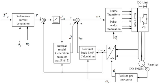
Figure 7.
Overall block diagram for control scheme of Mohamed. Reprinted with permission from ref. [62]. Copyright 2008 IEEE.
The methods of feed-forward control compensation for thrust ripple in PMLSMs are concretely reported in [63,64,65,66,67]. In [63], a back-EMF compensation method is proposed to obtain a current control scheme independent of the back-EMF variation. In [64], field-oriented control (FOC) is applied, and the components of thrust ripple are extracted by FEM; then, the thrust ripple is compensated by controlling the q-axis current component. In [65], a feed-forward compensator that can generate dither signals is designed to suppress the force ripple.
In [66], the thrust ripple, which is caused by mismatched current waveforms and unbalanced amplifier gain or motor phase, is reduced by optimizing the phase current waveform. The optimized current waveforms are implemented in a motion controller, and the experimental results show that the tracking performance of the PMLSM is significantly improved by using the proposed method.
Moreover, a data-driven variable-gain iterative feed-forward approach is presented in [67] to reduce stochastic disturbance, and the robustness of model uncertainty is improved.
In order to meet the requirements of high stability and strong robustness in parameter variation, the adaptive robust control algorithm is widely implemented in PMLSM systems. Bin Yao et al. conducted substantial digital motion control strategies known as adaptive robust control (ARC) to compensate for major nonlinearities [51,68]. In [51], a discontinuous projection-based ARC controller was designed in particular, and the results indicated that the proposed algorithm exhibits superior tracking performance and avoids the cost of offline identification. However, it tends to compensate for only one or several types of disturbance simultaneously. Then, in [68], an ARC algorithm that offers a complete, simultaneous compensation scheme was used for all major nonlinearities, including coulomb friction, cogging force, and saturating electromagnetic field effect during large driving current. The experimental results show that the proposed approach can achieve an effective overall tracking performance and that it is more suitable for high-precision control.
Furthermore, relay feedback control [2,69], iterative learning control [70], and predictive control [71] can also effectively suppress thrust ripple in PMLSMs, but the key issues are obtaining the specific motion states and compensating for parameters’ variations [72,73,74].
According to the above discussions, thrust force and friction compensation have been extensively studied during recent decades, and it is difficult to eliminate force ripple using a single method. Therefore, further investigations may focus on the combination of both optimal motor designs and optimal control methods.
3. Thermal Effects
Thermal effects have a significant impact on the parameters and performance of PMLSMs. As temperature variations lead to variations in the electrical parameters of PMLSMs and thermal errors, the overall performance, such as dynamic response and precision, will be compromised. Moreover, the maximum temperature increase is the limiting factor of the electric insulation grades in the design phase, and the lifetime of the stator winding has a close relationship with thermal effects. It is necessary to investigate the thermal behavior of linear motors and compensate for the influence induced by thermal effects. This section firstly introduces the heat sources of PMLSMs, and then, different thermal analysis methods are presented and compared. Lastly, thermal compensation methods for linear motor systems are discussed.
3.1. Heat Sources of Linear Motors
As PMLSMs feature high thrust density, high acceleration, and high speed, the main heat sources of PMLSMs include electromagnetic loss (such as copper loss, iron loss, and eddy current loss) and friction [75,76,77]. In general, copper loss is a major part of the total loss, especially in high thrust operation mode with a high current density. Copper loss has a close relationship with the temperature of the windings, as the resistance increases with temperature increase. However, iron loss is the dominant loss in high-frequency operation mode, of which hysteresis loss and eddy current loss are the main components.
Heat source identification is important for the thermal effect management of PMLSMs. Based on the heat source information, more effective measures could be taken to improve the PMLSM performance and working reliability.
3.2. Thermal Analysis of PMLSM
Thermal characteristic models of PMLSMs are essential for predicting temperature distribution. Compared with rotating motors, thermal analysis of PMLSMs is more difficult due to the open structure, large modeling area (at least half of the entire PMLSM), and complex working modes (reciprocating acceleration/deceleration operation, intermittent duty, etc.) [10]. In general, the methods for PMLSM thermal analysis can be summarized as the lumped parameter thermal network (LPTN) and numerical modeling [77,78]. Both methods are proven to be effective to predict the temperature distribution.
The LPTN method uses simplified areas with lumped parameters to represent the complex structures [78]. The LPTN method is characterized by its efficiency, as it relies on an analytical model to determine the temperature distribution. The more detailed the thermal network is, the more accurately it can predict the temperature distribution. When it comes to simple structures, the temperatures predicted using the LPTN method have been found to be in good agreement with numerical simulation results. However, it does take effort to establish accurate models. Further validation and modification through simulation or experimental measurements are needed to make the LPTN method applicable to various motors under different working conditions. Numerical methods, which include finite element analysis (FEA) and computational fluid dynamics (CFD), are strong and valid tools to predict more accurate temperature distributions, even for motors with complex structures. However, they are rather time-consuming and have high computational costs [10,75,78,79,80].
Many publications have reported thermal analyses of PMLSMs using the LPTN method. Tessarolo et al. derived an accurate 3D thermal model of a PMLSM through the LPTN approach, as shown in Figure 8. They proposed computationally efficient techniques that can solve the model analytically based on some simplified hypotheses. The analytical results and experimental measurements have good agreement, which validates the proposed method [81].
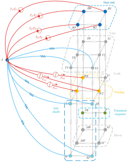
Figure 8.
Three-dimensional thermal network including heat sink nodes. Reprinted with permission from ref. [81]. Copyright 2015 IEEE.
Chow et al. analyzed the thermal deformation of a precision carriage driven by a PMLSM, as shown in Figure 9. They claimed that the joule heat from the motor coils was the main heat source. Furthermore, by comparing the experimental and simulation results, they concluded that thermal boundary conditions were important for accurate estimation of the thermal deformation [82]. Using knowledge of the coil arrangement types, as illustrated in Figure 10, they established a three-dimensional model and adopted the finite difference method to calculate the heat conducted to the carriage [83]. The theoretical calculations were verified with experiments using different current loads. With this method, a temperature prediction model could be obtained with sufficient accuracy.
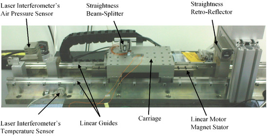
Figure 9.
Assembled single-axis stage with a linear motor (LM) and roller bearings for straightness measurements. Reprinted with permission from ref. [82]. Copyright 2012 Elsevier Ltd.
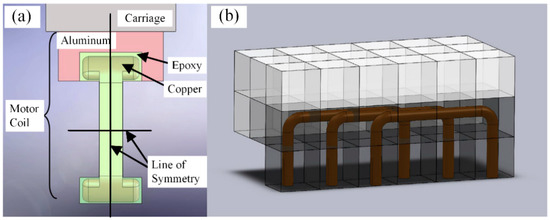
Figure 10.
(a) Line of symmetry shown to reduce number of elements and (b) structure of elements for reduced model of motor coils. Reprinted with permission from ref. [83]. Copyright 2015 Elsevier Ltd.
Liu et al. proposed a simplified 3D fluid model to calculate the fluid field of a PMLSM. On the premise of sufficient calculation accuracy, this method reduced the computation time and provided improved practicability. Without considering the inner structure of the mover, the mesh number of the simplified fluid model was significantly reduced, as shown in Figure 11. The thermal simulation results from the electromagnetic-fluid-thermal coupled field are consistent with the experimental results and the error is less than 10%. Moreover, the computation time could be reduced from nearly 110 h to less than 85 h [75].
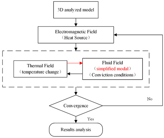
Figure 11.
Analysis flow chart of the three-dimensional (3D) electromagnetic-fluid-thermal (EM-FT) coupled field. Reprinted with permission from ref. [75]. Copyright 2015 Elsevier Ltd.
Lu et al. concluded that the temperature increase was a major problem limiting the LM performance. They noted that the thermal analysis of water-cooled PMLSMs was poorly documented. Thus, they investigated the thermal performance of a water-cooled 14-pole and 12-slot PMLSM under continuous duty, short-time duty, and intermittent duty. A one-dimensional thermal resistance network analysis model, as shown in Figure 12, and a two-dimensional FEA model were constructed to obtain the temperature distribution. Thereafter, the impact of the temperature increase on the motor thrust force, efficiency, and power factor was studied through experiments and simulations [10,84]. Furthermore, the water flow rate could be optimized according to the demands [85].
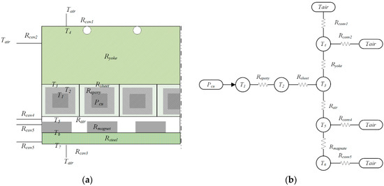
Figure 12.
Lumped parameter thermal network (LPTN) model of a PMLSM. (a) Simplified motor structure. (b) Simplified thermal resistance network. Reprinted with permission from ref. [10]. Copyright 2015 IEEE.
Zhang et al. demonstrated that PMLSMs are suitable for use in ultra-precision positioning, computerized numerical control machine tools, and other processing fields. They proposed an ironless linear synchronous motor with a cooling system, as illustrated in Figure 13. The analytical model of the PMLSM was formulated in 2D Cartesian coordinates. The analytical solution for the flux density in the cooling jacket was established based on the separation of variables method with appropriate boundary conditions. The eddy current braking force induced in the cooling system and the influence of the motor parameters on the eddy current braking force were investigated and validated using the FEM. These authors built a prototype and validated the no-load back-EMF and static thrust by means of experimental results, as shown in Figure 14 [86].
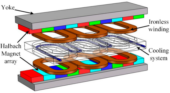
Figure 13.
Novel ironless linear synchronous motor with cooling system. Reprinted with permission from ref. [86]. Copyright 2016 MDPI.
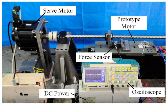
Figure 14.
Test platform for linear synchronous motor. Reprinted with permission from ref. [86]. Copyright 2016 MDPI.
3.3. Controller Design to Compensate
As temperature variations have significant impacts on the parameter accuracy of PMLSMs, such as the winding resistance and the magnetic properties of PMs, controller design with robustness to parameter uncertainty and thermal error modeling are the two main research aspects to compensate for the thermal effects.
Yan et al. addressed the multi-parameter online identification of a long-mover PMLSM based on the extended Kalman filter. The flux linkage and stator resistance were simultaneously identified [87]. Tavallaei et al. designed a robust controller that enables prolonged motion control of a single control input ultrasonic motor (USM) system. The temperature variations significantly affect the dynamic characteristics of the motor and change the resonance frequency of the piezoelectric material. They adopted a Lyapunov function redesign (LFR) robust controller to deal with the uncertainties of the system while ensuring an acceptable performance and stability [88]. Dülk et al. developed a method for estimating the electrical resistance of the coil in a single-coil linear solenoid actuator which is subject to pulse width modulation (PWM) drive conditions [89].
In addition, the PMLSM is one of the heat sources which can cause thermal errors in the direct-driven linear feed systems. In ultra-precision machines, thermal errors have a dominant influence on precision as they are related to more than half of the total errors [90,91]. Many studies focus on thermal error compensation in the linear feed system.
Lin et al. analyzed the influence of thermal dynamic hysteresis on the direct feed axis. Based on one-dimensional heat conduction and thermal expansion theory modeling, an error compensation method of the thermal dynamic characteristic is proposed [92]. Sun et al. optimized the design of important machine parts from the perspective of thermodynamics to improve the thermal performance of an ultra-precision machine tool. They conducted FEM to identify the weak points [93]. Zou et al. presented a thermo-mechanical model to quantify the dynamic error of a high-precision worktable in which both the internal heat sources and environmental thermal fluctuations were considered. The presented model provided a solution for ordinary workshops in environments where the temperature is not controlled to compensate for the thermal errors of the moving units [94]. Lei et al. presented a data-driven modeling method of the thermal error–temperature relationship for the dual-drive ball-screw feed axis. With the low cost and easily accessible unlabeled temperature data under various operation conditions, a co-training semi-supervised support vector machine for the regression method was adopted. The thermal error model was validated through experiments and outperformed the genetic algorithm support vector machines for regression in compensation [95].
In conclusion, the thermal behavior of PMLSMs requires further investigation. For the reduction in heat sources, future work may focus on optimal motor designs considering both the thrust density and efficiency. As the temperature increase is inevitable, forced cooling and insulation techniques are necessary to reduce the impact on the accuracy. The temperature field under certain operation conditions can be predicted using thermal analysis with the LPTN and numerical methods. Moreover, the prediction accuracy can be improved by adopting the improved 3D multi-physical field method with accurate boundary conditions. The simulations should be validated by experiments, including the measurement of the temperature field and thermal deformations. Temperature variations will significantly affect the parameters and dynamic characteristics of the PMLSMs, and robust controllers and thermal error compensation methods for linear motor systems may be combined with the data-driven methods to further mitigate the overall thermal effects.
4. Residual Vibration
In this section, residual vibrations are suppressed from three parts, including the input and output of controllers, the controller structure, and the physical characteristics of the controlled object. For the smooth input command and vibration reduction, trajectory planning algorithms are proposed first. Then, feed-forward and feedback controllers are proposed to achieve good dynamic performance and accurate tracking. Subsequently, considering the low-damping characteristic of PMLSMs, vibration suppression methods applying the additional dampers are introduced.
4.1. Trajectory Planning Algorithms
In order to achieve precise motion, trajectory planning is implemented to generate suitable input commands for minimizing vibration and overshoot in position, velocity, and current loops [96,97,98].
Point-to-point motion is most commonly used in PMLSMs, which is required to move to the specified position at a specified time. The desired motion profile must be generated beforehand [99]. The trapezoidal velocity profile is the common planning algorithm. The velocity command is switched from constant acceleration to constant velocity and then constant deceleration [70]. The acceleration will change from a positive constant to 0 and then to a negative constant. These discontinuities of the acceleration make the jerk exhibit infinite values and, therefore, cause the vibration and overshoot in the position as well as the velocity [69]. For smoothing the acceleration and minimizing the jerk, trigonometric and polynomial models have been studied by many scholars. K. D. Nguyen presented an s-curve motion model, including trigonometric and polynomial functions. This algorithm can provide a specialized trajectory considering the bounded jerk and operation time [96]. However, some generated trajectories could not be implemented to PMLSMs owing to the limitations of mechanical structure and electrical properties.
In terms of the dynamics and physical limitations, the time-optimal control of s-curve motion profiling was proposed in [100]. The mathematical expressions of the switching curve and surface are explicitly described. As shown in Figure 15, the feedback form of the time-optimal solution is applied to a linear motor and provides faster trajectories than the improved s-curve motion profiling. Furthermore, in order to achieve the minimum time transient response and excellent tracking accuracy, M. Yuan proposed a two-loop control structure, as shown in Figure 16. It includes the online trajectory re-planning algorithm and an adaptive robust controller [1]. The re-planning algorithm is used to maximize the converting speed of the transient response. Therefore, this cascade controller can achieve high steady-state accuracy under a system’s kinematic/dynamic constraints.
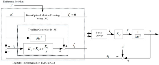
Figure 15.
Configuration of the digital signal processor (DSP)-based control system built for an experiment. Reprinted with permission from ref. [100]. Copyright 2003 IEEE.
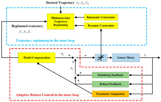
Figure 16.
The control structure of the online trajectory re-planning algorithm and adaptive robust controller. Reprinted with permission from ref. [1]. Copyright 2019 IEEE.
In conclusion, for smooth movement, trajectory planning algorithms optimizing displacement, velocity, and acceleration are necessary. Simultaneously, the generated trajectory needs to meet some limiting conditions, such as the system kinematic/dynamic constraints, operating time, and expended energy. Thus, low residual vibration of the PMLSM can be achieved.
4.2. Feed-Forward and Feedback Control Structure
Achieving a fast transient response and high steady-state tracking accuracy simultaneously is a challenge for linear motor systems in the presence of kinematic and dynamic constraints, various parametric uncertainties, and uncertain nonlinearities [1,101]. In high-speed and high-precision motion systems equipped with a linear motor, typically, the vast majority of the input actuator current is provided by feed-forward control to achieve rapid tracking. Feedback control is normally applied to maintain system stability and robustness. In order to improve the trajectory tracking performance, a feedback and feed-forward control structure is introduced for precision motion control of PMLSMs.
Usually, velocity and current feed-forward control loops are employed in high-velocity and high-acceleration systems. The basic three-loop control was found to be insufficient for high-velocity systems due to the mover delays from the command [1]. Without the feed-forward control loop, the system will easily produce a large overshoot and long settling time in the stage of high acceleration. In [102], a velocity feed-forward loop was presented for a rope-less elevator and realized a high positioning precision. The feed-forward velocity was calculated by differentiating the planning trajectory. Furthermore, in [102], the current feed-forward loop provided a fast dynamic response. Compared with the conventional three-loop control, the transient vibration of the linear motor is reduced.
Owing to parametric uncertainties and nonlinear disturbance, there are stable errors at places where the mover has a high frequency and high acceleration. Considering the repetitive operation of PMLSMs, the uncertain factors can be modeled or learned and used as a feed-forward input. Feed-forward and feedback controller structures of PMLSMs with learning ability are presented as follows.
In [103], a controller combing the model-based feed-forward and adaptive feedback gain of jerk was designed. Additionally, the adaptive feedback gain of jerk is updated by an exponential function, as shown in Figure 17. The stability of the closed-loop system was proven by the Lyapunov approach. According to the experimental results, the proposed control scheme can achieve robust, precise tracking performance and reduce the residual vibration.
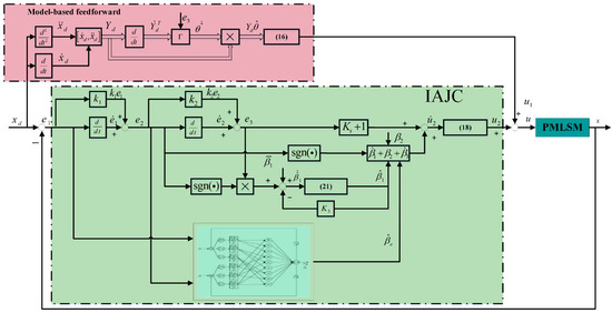
Figure 17.
Control scheme for PMLSM servo system. Reprinted with permission from ref. [103]. Copyright 2020 IEEE.
In [104], with the simple zero-phase filtering technique, an iterative learning controller is applied as a feed-forward controller, as shown in Figure 18. Furthermore, a relay-tuned proportional–integral–derivative (PID) feedback controller is designed using an automatic relay tuning method. In [105], a feed-forward controller in the repetitive control system is modified online using the system parameter identifier to improve the output convergence.
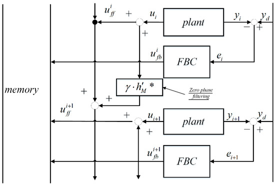
Figure 18.
Block diagram of zero-phase filter-based iterative learning control. Reprinted with permission from ref. [104]. Copyright 2001 IEEE.
As shown in Figure 19, a neural network learning adaptive robust controller was developed. The adaptive part and robust part were designed to meet the challenge of parametric variations due to the structure of linear motors and variable reference trajectories. A neural network was designed based on input and output data to enhance the robustness against uncertain random disturbances [4].
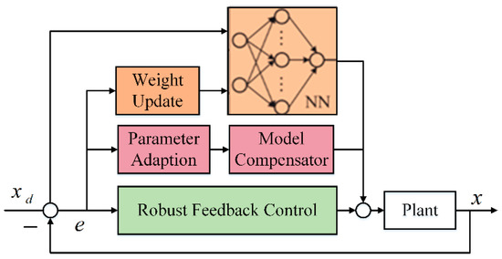
Figure 19.
Neural network learning adaptive robust controller framework. Reprinted with permission from ref. [4]. Copyright 2017 IEEE.
As mentioned above, feed-forward control considering the normal dynamic model can improve the dynamic performance. In terms of repetitive motion, a feed-forward controller with self-learning, such as iterative learning, fuzzy control, reinforcement learning, neural networks, etc., can obtain an excellent performance in terms of transient response and even approximately error-free trajectory tracking.
4.3. Damper
In addition to the control algorithm, for reducing the residual vibration of PMLSMs, a direct method is to increase the physical damping. Common types of dampers applied to PMLSMs include a liquid damper, a mechanical friction damper, and an electromagnetic damper.
In [106], P. Ma investigated the performance of a magneto-rheological fluid (MRF) by applying different control parameters and moving mass, as shown in Figure 20. Under the acceleration feed-forward proportion-proportion integration (P-PI) controller, the overshoot, rising time, and settling time of the PMLSM are proposed. Then, by comparing these dynamic performances with the enabled MRF, the presented damper is shown to improve the dynamic response and reduce the residual vibration. However, due to the high nonlinearity of the MRF damping, the suppression performance of the residual vibration in the PMLSM will be limited. Furthermore, the sealing of the MRF also becomes a large influence factor for wide applications.

Figure 20.
Block diagram of P-PI controller with acceleration feed-forward of the linear feed drive with magneto-rheological fluid (MRF) damper. Reprinted with permission from ref. [106]. Copyright 2010 IEEE.
As shown in Figure 21, a novel auxiliary suppression device, the tuned viscoelastic damper (TVD), was designed to increase the damping of a PMLSM [107]. Through the Kelvin model and finite element analysis, the motion characteristics of the proposed damper were analyzed. Finally, the experiments were performed and the results proved that the TVD is effective in increasing the damping of the PMLSM. The damping of this damper heavily depends on the viscoelasticity of the contact surface. However, with the abrasion of the contact surface owing to long-term use, the characteristic of suppression will be degraded.
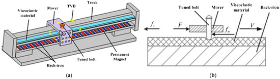
Figure 21.
(a) System of PMLSM with tuned viscoelastic damper (TVD); (b) cross-sectional view of PMLSM with TVD. Reprinted with permission from ref. [107]. Copyright 2018 IEEE.
Compared with the conventional mechanical friction damper, the eddy current damper (ECD) has the advantages of no mechanical contact and no liquid leakage. In [108], a dual-sided hybrid excitation eddy current damper (ECD) was presented to actively suppress the vibration of a linear motor during decelerating and stopping stages, as shown in Figure 22. With the proposed eddy current damper, the results show that the amplitude of the in-position error and the settling time are reduced by 68.88% and 33.33%, respectively. Similar characteristic dampers, including the theory model [109], performance analysis [110], and different conductor materials [111], were also introduced.
Figure 22.
Dual-sided hybrid excitation eddy current damper. Reprinted with permission from ref. [108]. Copyright 2020 IEEE.
As mentioned above, residual vibration increases the settling time and reduces the positioning accuracy. In order to weaken the residual vibration, the command input and structure of controllers have been studied in numerous works. To avoid discontinuous acceleration and jerk, trajectory planning technology is proposed to smooth the command input. Under specialized operating conditions, time optimization and kinematics/dynamics constraints need to be considered. For the high-speed and high-frequency motion operation of a PMLSM, feed-forward and feedback control structures can improve the dynamic performance and steady-state accuracy. Moreover, the additional equipment, increasing the physical damping of the controlled object, can directly weaken the amplitude of residual vibration and reduce the settling time. This additional damper can be decoupled from the controller and achieve active vibration suppression. With the requirement of multi-working conditions, the design and operation of active dampers would receive more attention.
5. Load Disturbances
Disturbance observers are widely applied to suppress load disturbances. They can quantify a disturbance according to the output of a motion system without a disturbance model. The general structure of a disturbance observer includes a low-pass filter Q(s) and an inverse of the plant model. The low-pass filter Q(s) makes Q(s)P−1(s) a physically realizable system and suppresses noise at high frequencies, as shown in Figure 23. The disturbance observer has drawn the attention of researchers due to the advantage of its compatibility with feedback and feed-forward control. Therefore, it has become a widely used control scheme in load disturbance suppression, as shown in Figure 24.
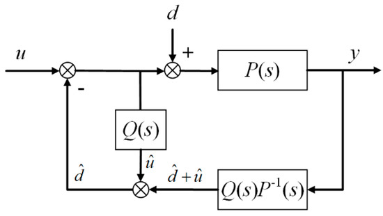
Figure 23.
The basic control structure of a disturbance observer.
Figure 24.
The control block diagram of a force disturbance observer (DOB). Reprinted with permission from ref. [7]. Copyright 2010 MDPI.
5.1. Load Disturbance Rejection in Periodic and Aperiodic Motion
The PMLSM is frequently applied for achieving a desired motion trajectory. Generally, a periodic motion is demanded, such as the stepping motion in a bonding machine [112]. Periodic adaptive learning control has shown some advantages in improving the tracking performance for periodic motion in [61]. The disturbance in periodic motion is normally periodic as well. Consequently, the adaptive learning method could be applied on the disturbance observer. Kwanghyun [113] proposed a periodic adaptive disturbance observer (PADOB); the parameters of disturbance observation were updated for each control period with the adaptation law, and the disturbance would, therefore, be well suppressed when parameters converged. The authors theoretically proved that position tracking errors converge to zero asymptotically, and the experimental results showed that the root mean square (RMS) of error was reduced to about 0.5 μm. Zhao [114] applied the PADOB on a PMLSM based on DSP TMS320 LF2812A, and the zero-phase low-pass filter was implemented as the Q-filter of the observer. Accordingly, the tracking error of a trapezoid trajectory with maximum speed of 0.5 m/s was reduced to about 3 μm, as shown in Figure 25. The results show that the PADOB is effective for suppressing periodic disturbances.
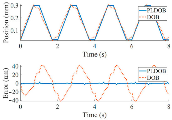
Figure 25.
The experimental results of periodic adaptive disturbance observer (PADOB) on trapezoid trajectory tracking. Reprinted with permission from ref. [114]. Copyright 2018 CNKI.
However, there are non-repetitive disturbances in PMLSM motion systems, such as a sudden payload change, or the motion trajectory could be non-repetitive. The performances of iterative learning methods are obviously degraded by irregular disturbances, since the iterative process cannot observe the random disturbance and perform an effective tracking command. To solve this problem, Duan [115] proposed a model-free adaptive iterative learning control with feedback and feed-forward control (FFMFAILC) to reject non-repetitive load disturbances. The dynamic linearization technique is introduced in the iteration domain and only the input–output (I/O) data of the controlled plant are used. The FFMFAILC, therefore, shows better tracking performance compared to other methods, as shown in Figure 26.

Figure 26.
The tracking performance comparison between feed-forward and feedback model-free adaptive iterative learning control (FFMFAILC) and MFAILC, where FFMFAILC1 is the simulation results and FFMFAILC2 is the experimental results. Reprinted with permission from ref. [115]. Copyright 2019 IEEE.
Further to feedback and feed-forward control, an extended state observer (ESO) has been introduced to repetitive control and iterative learning control to suppress non-periodic disturbances. Sayem [116] combined an ESO and repetitive control and showed the control block diagram, as shown in Figure 27. The results show that the periodic trajectory tracking is guaranteed by repetitive control, and the non-periodic disturbance is suppressed by the ESO. Numerical experiments were implemented to verify the feasibility of ESO-based repetitive control when the disturbances’ waveform includes sinusoidal, hyperbolic, chirp, step, and ramp. The ESO was also introduced to iterative learning control. Hui [117] proposed ESO-based data-driven iterative learning control. The ESO is applied to estimate the random initial states and disturbances as a whole extended state, which overcomes the disadvantage of iterative learning control, whereby identical initial states are demanded for convergence. Zhou [118] proposed modified repetitive control to reject nonlinear non-periodic disturbance with state-dependent uncertainty. An equivalent input disturbance (EID) [119] estimator was introduced and constructed by a full-order state observer with a variant system matrix. Simultaneously, the EID estimator was incorporated into a linear repetitive control law, and the modified repetitive control was derived.
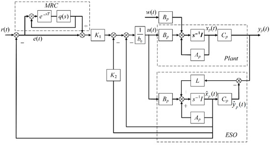
Figure 27.
The control block diagram of extended state observer (ESO)-based repetitive control. Reprinted with permission from ref. [116]. Copyright 2017 IEEE.
For applications with force control, load disturbance estimation is demanded. Hsueh [120] applied the Luenberger observer in the impedance control of a linear servo motor as a haptic system; the external force is estimated, and the desired dynamic behavior is achieved. The Luenberger observer can approximate to the original system; therefore, the system states can be well reconstructed, and some sensors can be replaced by the Luenberger observer. However, system uncertainty will degrade the performance of the Luenberger observer.
The Luenberger observer and the ESO handle disturbances in different ways; the Luenberger observer can reconstruct exogenous disturbances, while the ESO lumps the unknow disturbances, unmodeled dynamics, and nonlinearity of a system together. For ESO implementation, only the relative degree of the system under consideration is required. Basically, it is a modeless method, and state reconstruction is, therefore, unavailable. The EID estimator is closely related to ESO; the difference is that the EID estimator estimates the disturbance at the control input channel instead of the disturbance itself. There are other types of DOB reported in [121]—for example, a nonlinear DOB established based on the sliding mode concept [122]. However, few studies discuss nonlinear DOB applications on PMLSMs, while most of the literature focuses on the theoretical research. Application of nonlinear DOBs for PMLSMs will be a prospective research topic, as higher precision and a faster response speed will further highlight the advantages of PMLSMs.
5.2. Load Disturbance Rejection in Feed System
PMLSMs are also widely applied in the feed system of machine tools [123]; it often suffers from cutting force disturbance during the machining process. A milling machine tool with a linear motor feed system is presented in Figure 28. The amplitudes of cutting force have large variations, which causes the instability of the controller. To solve this problem, Choi [124] applied the normalized coprime factorization method and a multiple input multiple output (MIMO) H∞ controller to improve the robustness. The tracking error was reduced to almost half of that of a PID controller with the implementation of the MIMO H∞ controller. The capability to counteract external disturbance force is also termed as dynamic stiffness. Altintas [125] proposed a disturbance adaptive discrete-time sliding mode controller (DADSC), and the disturbance recovery algorithm was implemented to refine the estimated disturbance force. The block diagram of the DADSC is presented in Figure 29. The dynamic stiffness improvement was verified by experimental results. The transfer function gain between the tool and the workpiece decreased by 5 dB on average and decreased by 10 dB at the resonance frequency region, which indicates that the disturbance was effectively attenuated from the workpiece to the machine tool.
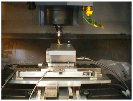
Figure 28.
The milling machine tool with a linear motor feed system. Reprinted with permission from ref. [124]. Copyright 2005 Elsevier Ltd.
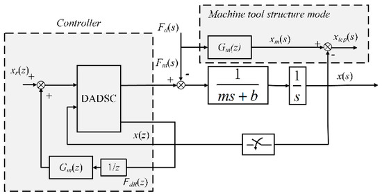
Figure 29.
The block diagram of the disturbance adaptive discrete-time sliding mode controller with disturbance recovery. Reprinted with permission from ref. [125]. Copyright 2009 Elsevier Ltd.
The cutting force model [126] could be implemented in the control of PMLSM feed systems and served as a disturbance suppression controller in feed-forward form. Duan [127] simplified the cutting force as a harmonic disturbance at 60 Hz with an additional dc component. Based on the simplified cutting force model, the positioning error is less than 10 um. Later, Duan [128] considered the variable-frequency disturbance case and implemented the proxy-based control allocation method. The controller gain was characterized as a function of the disturbance force frequencies and the Lyapunov stability was proven.
Cutting force modeling [129] and chatter vibration [130] are hot research topics in machine tool processing. However, the research results have not been fully applied in disturbance feed-forward control, where a linear motor serves as the feed system. The authors believe that disturbance suppression performance could be further improved with the assistance of cutting force modeling and compensation.
Load disturbance may not only influence the output of a PMLSM but also the whole motion system, including the controller, current driver, and the parameters of the PMLSM. Yang [131] considered the dynamic electromechanical coupling effect of linear motor feed systems in machine tools. For example, the pitch vibration may be influenced by the load disturbance, and the uniformity of the air gap, therefore, deteriorates, as shown in Figure 30. Yang’s later works [132,133] include the electromechanical coupling effect caused by variation of the thrust force spectrum, the loads, the encoder’s errors, and cutting force. The investigation of the electromechanical coupling effect provides a system-level consideration. The influence of the exogenous disturbances is highlighted by the electromechanical coupling analysis, which could be utilized as a guidance for disturbance suppression in controller design.
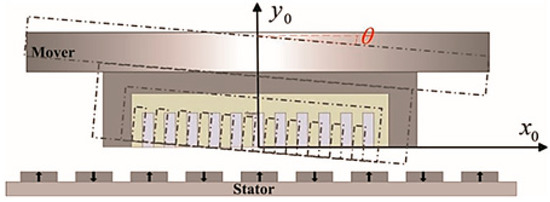
Figure 30.
The influence of pitch vibration on the air gap [131]. Reprinted with permission from ref. [131]. Copyright 2015 Elsevier Ltd.
6. Conclusions
The PMLSM offers the unique advantages of high acceleration and high positioning accuracy in linear feed systems. Simultaneously, the lack of an intermediate transmission mechanism necessitates a more complex controller. The main factors that induce positioning errors, including cogging force, friction force, thermal effects, residual vibration, and load disturbance, have been investigated to demonstrate their generation mechanisms and the according suppression methods in this paper.
Many studies have been verified under specific testing conditions and disturbances. Thrust force and friction can be weakened via optimization of the structure and compensation of the controller. The temperature rise is easily limited by the forced cooling and insulation techniques based on the calculation and measurement of the temperature distribution. Accordingly, the controller considering the temperature suppression can improve the system dynamic characteristics under different temperatures. Residual vibration can be suppressed through trajectory planning, controller design, and an additional damping device. Load disturbance is often estimated by disturbance observers and suppressed by the controller.
However, the coupling of the multi-disturbance strongly affects the operating accuracy of the PMLSM in actual engineering applications. The suppression method only considering the specified disturbance is limited in improving the accuracy of the overall system. The data-driven methods have been verified to be effective for many nonlinear strongly coupled nonlinear systems in industrial applications [134]. As a development trend, considering the complexity of the control object, a controller designed based on the input and output signals would be more efficient.
Author Contributions
All authors conceived the paper and design the review study. X.W. conducted the search and analysis of the related literature and drafted the paper; F.C. collected and analyzed the references and drafted the section on residual vibration; N.S. drafted the section on thrust ripple and friction; R.Z. drafted the section on thermal effects; X.H. drafted the section on load disturbances; C.Z. and G.Y. initialized the writing of this paper and structured and thoroughly revised the manuscript. All authors have read and agreed to the published version of the manuscript.
Funding
This research was funded by the National Key Research and Development Program of China (Grant No.2018YFF01011502), Zhejiang Science and Technology Department (Grant No. 2018C35041), Major Program of Zhejiang Provincial Natural Science Foundation of China (Grant No. D21E070002), the joint funds of the National Natural Science Foundation of China and Zhejiang Province (Grant No. U1609206), and Key Laboratory of Robotics and Intelligent Manufacturing Equipment of Zhejiang Province.
Institutional Review Board Statement
Not applicable.
Informed Consent Statement
Not applicable.
Data Availability Statement
No new data were created or analyzed in this study. Data sharing is not applicable to this article.
Conflicts of Interest
The authors declare no conflict of interest. The funders had no role in the design of the review; in the collection, analyses, or interpretation of data; in the writing of the manuscript, or in the decision to publish the results.
References
- Yuan, M.; Chen, Z.; Yao, B.; Liu, X. Fast and accurate motion tracking of a linear motor system under kinematic and dynamic constraints: An integrated planning and control approach. IEEE Trans. Control Syst. Technol. 2019. [Google Scholar] [CrossRef]
- Chen, S.L.; Tan, K.K.; Huang, S.; Teo, C.S. Modeling and Compensation of Ripples and Friction in Permanent-Magnet Linear Motor Using a Hysteretic Relay. IEEE/ASME Trans. Mechatron. 2010, 15, 586–594. [Google Scholar] [CrossRef]
- Boduroglu, A.; Gulec, M.; Demir, Y.; Yolacan, E.; Aydin, M. A New Asymmetric Planar V-Shaped Magnet Arrangement for a Linear PM Synchronous Motor. IEEE Trans. Magn. 2019, 55, 1–5. [Google Scholar] [CrossRef]
- Wang, Z.; Hu, C.; Zhu, Y.; He, S.; Yang, K.; Zhang, M. Neural network learning adaptive robust control of an industrial linear motor-driven stage with disturbance rejection ability. IEEE Trans. Ind. Inform. 2017, 13, 2172–2183. [Google Scholar] [CrossRef]
- Chen, Y.-T.; Yu, C.-S.; Chen, P.-N. Feedback Linearization Based Robust Control for Linear Permanent Magnet Synchronous Motors. Energies 2020, 13, 5242. [Google Scholar] [CrossRef]
- Song, J.; Dong, F.; Zhao, J.; Lu, S.; Li, L.; Pan, Z. A new design optimization method for permanent magnet synchronous linear motors. Energies 2016, 9, 992. [Google Scholar] [CrossRef]
- Bascetta, L.; Rocco, P.; Magnani, G. Force Ripple Compensation in Linear Motors Based on Closed-Loop Position-Dependent Identification. IEEE/ASME Trans. Mechatron. 2010, 15, 349–359. [Google Scholar] [CrossRef]
- Wang, Y.; Yu, H.; Che, Z.; Wang, Y.; Zeng, C. Extended state observer-based predictive speed control for permanent magnet linear synchronous motor. Processes 2019, 7, 618. [Google Scholar] [CrossRef]
- Huang, X.Z.; Yu, H.C.; Zhou, B.; Li, L.Y.; Gerada, D.; Gerada, C.; Qian, Z.Y. Detent-Force Minimization of Double-Sided Permanent Magnet Linear Synchronous Motor by Shifting One of the Primary Components. IEEE Trans. Ind. Electron. 2020, 67, 180–191. [Google Scholar] [CrossRef]
- Lu, Q.; Zhang, X.; Chen, Y.; Huang, X.; Ye, Y.; Zhu, Z.Q. Modeling and Investigation of Thermal Characteristics of a Water-Cooled Permanent-Magnet Linear Motor. IEEE Trans. Ind. Appl. 2015, 51, 2086–2096. [Google Scholar] [CrossRef]
- Hao, X.; Peng, B.; Chen, Y.; Xie, G. Transient thermal model of a permanent magnet synchronous planar motor considering spreading thermal resistance. Appl. Therm. Eng. 2015, 81, 1–9. [Google Scholar] [CrossRef]
- Wen, T.; Xiang, B.; Wang, Z.; Zhang, S. Speed control of segmented PMLSM based on improved SMC and speed compensation model. Energies 2020, 13, 981. [Google Scholar] [CrossRef]
- Shao, K.; Zheng, J.; Wang, H.; Xu, F.; Wang, X.; Liang, B. Recursive sliding mode control with adaptive disturbance observer for a linear motor positioner. Mech. Syst. Signal Process. 2021, 146. [Google Scholar] [CrossRef]
- Wu, J.; Pu, D.; Ding, H. Adaptive robust motion control of SISO nonlinear systems with implementation on linear motors. Mechatronics 2007, 17, 263–270. [Google Scholar] [CrossRef]
- Aslan, D.; Altintas, Y. Prediction of Cutting Forces in Five-Axis Milling Using Feed Drive Current Measurements. IEEE/ASME Trans. Mechatron. 2018, 23, 833–844. [Google Scholar] [CrossRef]
- Barrenetxea, D.; Mancisidor, I.; Beudaert, X.; Munoa, J. Increased productivity in centerless grinding using inertial active dampers. Cirp Ann. Manuf. Technol. 2018, 67, 337–340. [Google Scholar] [CrossRef]
- Yang, X.J.; Liu, H.; Lu, D.; Zhao, W.H. Investigation of the dynamic electromechanical coupling due to the thrust harmonics in the linear motor feed system. Mech. Syst. Signal Process. 2018, 111, 492–508. [Google Scholar] [CrossRef]
- Zeng, L.; Chen, X.; Li, X.; Jiang, W.; Luo, X. A Thrust Force Analysis Method for Permanent Magnet Linear Motor Using Schwarz–Christoffel Mapping and Considering Slotting Effect, End Effect, and Magnet Shape. IEEE Trans. Magn. 2015, 51, 1–9. [Google Scholar] [CrossRef]
- Hu, C.; Yao, B.; Wang, Q. Coordinated Adaptive Robust Contouring Control of an Industrial Biaxial Precision Gantry with Cogging Force Compensations. IEEE Trans. Ind. Electron. 2010, 57, 1746–1754. [Google Scholar] [CrossRef]
- Reay, D.S.; Mirkazemi-Moud, M.; Green, T.C.; Williams, B.W. Switched reluctance motor control via fuzzy adaptive systems. IEEE Control Syst. 2002, 15, 8–15. [Google Scholar] [CrossRef]
- Wang, M.; Li, L.; Pan, D. Detent Force Compensation for PMLSM Systems Based on Structural Design and Control Method Combination. IEEE Trans. Ind. Electron. 2015, 62, 6845–6854. [Google Scholar] [CrossRef]
- Boldea, I.; Nasar, S.A. Linear Motion Electromagnetic Devices; Taylor & Francis: Abingdon, UK, 2001. [Google Scholar]
- Luo, Y.; Chen, Y.; Pi, Y. Cogging effect minimization in PMSM position servo system using dual high-order periodic adaptive learning compensation. ISA Trans. 2010, 49, 479–488. [Google Scholar] [CrossRef] [PubMed]
- Sebastian, T. Temperature effects on torque production and efficiency of PM motors using NdFeB magnets. IEEE Trans. Ind. Appl. 1995, 31, 353–357. [Google Scholar] [CrossRef]
- Sencer, B.; Shamoto, E. Effective Torque Ripple Compensation in Feed Drive Systems Based on the Adaptive Sliding-Mode Controller. IEEE-ASME Trans. Mechatron. 2014, 19, 1764–1772. [Google Scholar] [CrossRef]
- Aydin, M.; Gulec, M. Reduction of Cogging Torque in Double-Rotor Axial-Flux Permanent-Magnet Disk Motors: A Review of Cost-Effective Magnet-Skewing Techniques with Experimental Verification. IEEE Trans. Ind. Electron. 2014, 61, 5025–5034. [Google Scholar] [CrossRef]
- Zhu, Z.Q.; Chen, J.T.; Wu, L.J.; Howe, D. Influence of Stator Asymmetry on Cogging Torque of Permanent Magnet Brushless Machines. IEEE Trans. Magn. 2008, 44, 3851–3854. [Google Scholar] [CrossRef]
- Yamazaki, K.; Fukushima, Y. Effect of Eddy-Current Loss Reduction by Magnet Segmentation in Synchronous Motors with Concentrated Windings. IEEE Trans. Ind. Appl. 2011, 47, 779–788. [Google Scholar] [CrossRef]
- Lin, Y.K.; Lai, Y.S. Dead-Time Elimination of PWM-Controlled Inverter/Converter without Separate Power Sources for Current Polarity Detection Circuit. IEEE Trans. Ind. Electron. 2009, 56, 2121–2127. [Google Scholar] [CrossRef]
- Schoonhoven, G.; Uddin, M.N. Harmonic Injection-Based Adaptive Control of IPMSM Motor Drive for Reduced Motor Current THD. IEEE Trans. Ind. Appl. 2017, 53, 483–491. [Google Scholar] [CrossRef]
- Pan, Z.B.; Dong, F.; Zhao, J.W.; Wang, L.J.; Wang, H.; Feng, Y.Y. Combined Resonant Controller and Two-Degree-of-Freedom PID Controller for PMSLM Current Harmonics Suppression. IEEE Trans. Ind. Electron. 2018, 65, 7558–7568. [Google Scholar] [CrossRef]
- Armstrong-Hélouvry, B.; Dupont, P.; Wit, C.C.D. A survey of models, analysis tools and compensation methods for the control of machines with friction. Automatica 1994, 30, 1083–1138. [Google Scholar] [CrossRef]
- Ahn, H.S.; Chen, Y.Q.; Dou, H. State-periodic adaptive compensation of cogging and Coulomb friction in permanent-magnet linear motors. IEEE Trans. Magn. 2005, 41, 90–98. [Google Scholar] [CrossRef]
- Liu, C.T.; Hwang, C.C.; Li, P.L.; Hung, S.S.; Wendling, P. Design Optimization of a Double-Sided Hybrid Excited Linear Flux Switching PM Motor with Low Force Ripple. IEEE Trans. Magn. 2014, 50, 1–4. [Google Scholar] [CrossRef]
- Ji, J.; Yan, S.; Zhao, W.; Liu, G.; Zhu, X. Minimization of Cogging Force in a Novel Linear Permanent-Magnet Motor for Artificial Hearts. IEEE Trans. Magn. 2013, 49, 3901–3904. [Google Scholar] [CrossRef]
- Lu, Q.; Cheng, C.; Ye, Y.; Fang, Y. Slot/pole number combination research of PM linear motors with fractional slots per pole. Proc. CSEE 2012, 32, 68–74. [Google Scholar]
- Xia, J.; Shen, L.; Peng, B.; Sun, Y. Influences of cogging effects on normal force ripple in permanent magnet linear servo motors. Zhongguo Dianji Gongcheng Xuebao/Proc. Chin. Soc. Electr. Eng. 2015, 35, 2847–2853. [Google Scholar] [CrossRef]
- Xia, J.; Shen, L.; Peng, B.; Song, D. The magnet-staggered method to weaken the cogging effect normal force ripple of permanent magnet linear servo motor. Trans. China Electrotech. Soc. 2015. [Google Scholar] [CrossRef]
- Xia, J.K.; Li, W.Y.; Shen, L. Skew and End-Teeth Optimization in Reduce Permanent-Magnet Linear Synchronous Motor Normal Force Fluctuation. Adv. Mater. Res. 2012, 383–390, 4853–4859. [Google Scholar] [CrossRef]
- Tavana, N.R.; Shoulaie, A. Pole-shape optimization of permanent-magnet linear synchronous motor for reduction of thrust ripple. Energy Convers. Manag. 2011, 52, 349–354. [Google Scholar] [CrossRef]
- Hu, H.; Liu, X.; Zhao, J.; Guo, Y. Analysis and Minimization of Detent End Force in Linear Permanent Magnet Synchronous Machines. IEEE Trans. Ind. Electron. 2018, 65, 2475–2486. [Google Scholar] [CrossRef]
- Kim, S.-A.; Zhu, Y.-W.; Lee, S.-G.; Saha, S.; Cho, Y.-H. Electromagnetic Normal Force Characteristics of a Permanent Magnet Linear Synchronous Motor with Double Primary Side. IEEE Trans. Magn. 2014, 50. [Google Scholar] [CrossRef]
- Lee, S.-G.; Kim, S.-A.; Saha, S.; Zhu, Y.-W.; Cho, Y.-H. Optimal Structure Design for Minimizing Detent Force of PMLSM for a Ropeless Elevator. IEEE Trans. Magn. 2014, 50. [Google Scholar] [CrossRef]
- Cai, J.-j.; Lu, Q.; Huang, X.; Ye, Y. Thrust Ripple of a Permanent Magnet LSM with Step Skewed Magnets. IEEE Trans. Magn. 2012, 48, 4666–4669. [Google Scholar] [CrossRef]
- Chu, W.Q.; Zhu, Z.Q. Investigation of Torque Ripples in Permanent Magnet Synchronous Machines with Skewing. IEEE Trans. Magn. 2013, 49, 1211–1220. [Google Scholar] [CrossRef]
- Jung, I.S.; Yoon, S.B.; Shim, J.H.; Hyun, D.S. Analysis of forces in a short primary type and a short secondary type permanent magnet linear synchronous motor. IEEE Trans. Energy Convers. 1999, 14, 1265–1270. [Google Scholar] [CrossRef]
- Lim, K.C.; Woo, J.K.; Kang, G.H.; Hong, J.P.; Kim, G.T. Detent force minimization techniques in permanent magnet linear synchronous motors. IEEE Trans. Magn. 2002, 38, 1157–1160. [Google Scholar] [CrossRef]
- Baatar, N.; Yoon, H.S.; Pham, M.T.; Shin, P.S.; Koh, C.S. Shape Optimal Design of a 9-pole 10-slot PMLSM for Detent Force Reduction Using Adaptive Response Surface Method. IEEE Trans. Magn. 2009, 45, 4562–4565. [Google Scholar] [CrossRef]
- Chen, F.; Zhang, C.; Chen, J.; Yang, G. Accurate Subdomain Model for Computing Magnetic Field of Short Moving-Magnet Linear Motor With Halbach Array. IEEE Trans. Magn. 2020, 56, 1–9. [Google Scholar] [CrossRef]
- Zhu, L.; Jiang, S.Z.; Zhu, Z.Q.; Chan, C.C. Analytical Methods for Minimizing Cogging Torque in Permanent-Magnet Machines. IEEE Trans. Magn. 2009, 45, 2023–2031. [Google Scholar] [CrossRef]
- Chen, Z.; Yao, B.; Wang, Q. Accurate Motion Control of Linear Motors with Adaptive Robust Compensation of Nonlinear Electromagnetic Field Effect. IEEE-ASME Trans. Mechatron. 2013, 18, 1122–1129. [Google Scholar] [CrossRef]
- Zarko, D.; Ban, D.; Lipo, T.A. Analytical calculation of magnetic field distribution in the slotted air gap of a surface permanent-magnet motor using complex relative air-gap permeance. IEEE Trans. Magn. 2006, 42, 1828–1837. [Google Scholar] [CrossRef]
- Yeh, S.S.; Su, H.C. Development of friction identification methods for feed drives of CNC machine tools. Int. J. Adv. Manuf. Technol. 2011, 52, 263–278. [Google Scholar] [CrossRef]
- Villegas, F.J.; Hecker, R.L.; Pena, M.E.; Vicente, D.A.; Flores, G.M. Modeling of a linear motor feed drive including pre-rolling friction and aperiodic cogging and ripple. Int. J. Adv. Manuf. Technol. 2014, 73, 267–277. [Google Scholar] [CrossRef]
- Lu, Q.F.; Wu, B.C.; Yao, Y.H.; Shen, Y.M.; Jiang, Q. Analytical Model of Permanent Magnet Linear Synchronous Machines Considering End Effect and Slotting Effect. IEEE Trans. Energy Convers. 2020, 35, 139–148. [Google Scholar] [CrossRef]
- Zhu, Z.Q.; Wu, L.J.; Xia, Z.P. An Accurate Subdomain Model for Magnetic Field Computation in Slotted Surface-Mounted Permanent-Magnet Machines. IEEE Trans. Magn. 2010, 46, 1100–1115. [Google Scholar] [CrossRef]
- Chen, Z.; Kong, W.B.; Zhou, Y.; Qu, R.H.; Fedida, V. Thrust force ripple reduction of H-LVPMM based on dynamic harmonic current compensation. IET Electr. Power Appl. 2020, 14, 226–233. [Google Scholar] [CrossRef]
- Jahns, T.M.; Soong, W.L. Pulsating torque minimization techniques for permanent magnet AC motor drives—A review. IEEE Trans. Ind. Electron. 1996, 43, 321–330. [Google Scholar] [CrossRef]
- Li, X.J.; Wang, Y.G. Sliding-mode control combined with improved adaptive feedforward for wafer scanner. Mech. Syst. Signal Process. 2018, 103, 105–116. [Google Scholar] [CrossRef]
- Wu, J.H.; Liu, C.; Liu, Y.J.; Xiong, Z.H.; Ding, H. Force ripple compensation of the directly-driven linear motors via iterative tuning feed-forward controller. Proc. Inst. Mech. Eng. Part I J. Syst. Control Eng. 2019, 233, 1239–1247. [Google Scholar] [CrossRef]
- Zhang, W.; Nan, N.; Yang, Y.; Zhong, W.; Chen, Y. Force ripple compensation in a PMLSM position servo system using periodic adaptive learning control. ISA Trans 2019, 95, 266–277. [Google Scholar] [CrossRef] [PubMed]
- Mohamed, A.R.I.; El-Saadany, E.F. A Current Control Scheme with an Adaptive Internal Model for Torque Ripple Minimization and Robust Current Regulation in PMSM Drive Systems. IEEE Trans. Energy Convers. 2008, 23, 92–100. [Google Scholar] [CrossRef]
- Dong Seong, O.; Kwan Yuhl, C.; Myong Joong, Y. A discretized current control technique with delayed input voltage feedback for a voltage-fed PWM inverter. IEEE Trans. Power Electron. 1992, 7, 364–373. [Google Scholar] [CrossRef]
- Zhu, Y.-w.; Cho, Y.-H. Thrust ripples suppression of permanent magnet linear synchronous motor. IEEE Trans. Magn. 2007, 43, 2537–2539. [Google Scholar] [CrossRef]
- Tan, K.K.; Lee, T.H.; Dou, H.; Zhao, S. Force ripple suppression in iron-core permanent magnet linear motors using an adaptive dither. J. Frankl. Inst. Eng. Appl. Math. 2004, 341, 375–390. [Google Scholar] [CrossRef]
- Rohrig, C. Current waveform optimization for force ripple compensation of linear synchronous motors. In Proceedings of the 42nd IEEE Conference on Decision and Control, Maui, HI, USA, 9–12 December 2003; pp. 5891–5896. [Google Scholar] [CrossRef]
- Song, F.; Liu, Y.; Jin, W.; Tan, J.; He, W. Data-Driven Feedforward Learning with Force Ripple Compensation for Wafer Stages: A Variable-Gain Robust Approach. IEEE Trans. Neural Netw. Learn. Syst. 2020, 1–15. [Google Scholar] [CrossRef]
- Chen, Z.; Yao, B.; Wang, Q. Adaptive Robust Precision Motion Control of Linear Motors with Integrated Compensation of Nonlinearities and Bearing Flexible Modes. IEEE Trans. Ind. Inform. 2013, 9, 965–973. [Google Scholar] [CrossRef]
- Si-Lu, C.; Kiongtan, K.; Sunan, H. Limit cycles induced in type-1 linear systems with PID-type of relay feedback. Int. J. Syst. Sci. 2009, 40, 1229–1239. [Google Scholar] [CrossRef]
- Butcher, M.; Karimi, A. Linear Parameter-Varying Iterative Learning Control with Application to a Linear Motor System. IEEE-ASME Trans. Mechatron. 2010, 15, 412–420. [Google Scholar] [CrossRef]
- Kim, J.; Cho, K.; Choi, S. Lumped disturbance compensation using extended Kalman filter for permanent magnet linear motor system. Int. J. Control Autom. Syst. 2016, 14, 1–10. [Google Scholar] [CrossRef]
- Feng, B.; Mei, X.; Yang, J.; Enxu, M.U. Adaptive Compensation of Friction Error for Numerical Control Machine Tool. Hsi-Chiao Tung Ta Hsueh/J. Xi’an Jiaotong Univ. 2013, 47, 65–69+96. [Google Scholar] [CrossRef]
- Feng, B.; Mei, X.S.; Yang, J.; Huang, X.Y. Adaptive Configuration Method of Friction Compensation Pulse Characteristic Parameters. J. Shanghai Jiaotong Univ. 2014, 48, 713–718. [Google Scholar] [CrossRef]
- Feng, B.; Zhang, D.; Yang, J.; Guo, S. A Novel Time-Varying Friction Compensation Method for Servomechanism. Math. Probl. Eng. 2015, 1–16. [Google Scholar] [CrossRef]
- Liu, X.; Yu, H.; Shi, Z.; Xia, T.; Hu, M. Electromagnetic-fluid-thermal field calculation and analysis of a permanent magnet linear motor. Appl. Therm. Eng. 2018, 129, 802–811. [Google Scholar] [CrossRef]
- Kim, J.-J.; Jeong, Y.H.; Cho, D.-W. Thermal behavior of a machine tool equipped with linear motors. Int. J. Mach. Tools Manuf. 2004, 44, 749–758. [Google Scholar] [CrossRef]
- Yang, Y.; Bilgin, B.; Kasprzak, M.; Nalakath, S.; Sadek, H.; Preindl, M.; Cotton, J.; Schofield, N.; Emadi, A. Thermal management of electric machines. IET Electr. Syst. Transp. 2017, 7, 104–116. [Google Scholar] [CrossRef]
- Boglietti, A.; Cavagnino, A.; Staton, D.; Shanel, M.; Mueller, M.; Mejuto, C. Evolution and Modern Approaches for Thermal Analysis of Electrical Machines. IEEE Trans. Ind. Electron. 2009, 56, 871–882. [Google Scholar] [CrossRef]
- Aubry, J.; Ahmed, H.B.; Multon, B. Sizing Optimization Methodology of a Surface Permanent Magnet Machine-Converter System over a Torque-Speed Operating Profile: Application to a Wave Energy Converter. IEEE Trans. Ind. Electron. 2012, 59, 2116–2125. [Google Scholar] [CrossRef]
- Huang, X.; Li, L.; Zhou, B.; Zhang, C.; Zhang, Z. Temperature Calculation for Tubular Linear Motor by the Combination of Thermal Circuit and Temperature Field Method Considering the Linear Motion of Air Gap. IEEE Trans. Ind. Electron. 2014, 61, 3923–3931. [Google Scholar] [CrossRef]
- Tessarolo, A.; Bruzzese, C. Computationally Efficient Thermal Analysis of a Low-Speed High-Thrust Linear Electric Actuator with a Three-Dimensional Thermal Network Approach. IEEE Trans. Ind. Electron. 2015, 62, 1410–1420. [Google Scholar] [CrossRef]
- Chow, J.H.; Zhong, Z.W.; Lin, W.; Khoo, L.P. A study of thermal deformation in the carriage of a permanent magnet direct drive linear motor stage. Appl. Therm. Eng. 2012, 48, 89–96. [Google Scholar] [CrossRef]
- Chow, J.; Zhong, Z.; Lin, W.; Khoo, L.; Kiew, C. A finite-difference thermal model of a three-phase coreless linear motor as a heat source. Appl. Therm. Eng. 2015, 87, 605–614. [Google Scholar] [CrossRef]
- Zhang, X.; Lu, Q.; Zhang, Y.; Huang, X.; Ye, Y. Thermal characteristics study of a water-cooled permanent magnet linear motor. In Proceedings of the 2014 Ninth International Conference on Ecological Vehicles and Renewable Energies (EVER), Monte Carlo, Monaco, 25–27 March 2014; pp. 1–9. [Google Scholar] [CrossRef]
- Zhu, Z.Q.; Chen, Y.; Yao, Y.; Lu, Q.; Huang, X.; Ye, Y. Thermal modeling and analysis of double-sided water-cooled permanent magnet linear synchronous machines. COMPEL Int. J. Comput. Math. Electr. Electron. Eng. 2016, 35, 695–712. [Google Scholar] [CrossRef]
- Zhang, L.; Kou, B.; Jin, Y.; Chen, Y.; Liu, Y. Investigation of an Ironless Permanent Magnet Linear Synchronous Motor with Cooling System. Appl. Sci. 2016, 6, 422. [Google Scholar] [CrossRef]
- Yan, L.; Zhang, D.; Bai, Z.; Ye, P.; Zhang, C. Online Multi-parameter Identification of Long-mover Permanent Magnet Linear Motor. In Proceedings of the 2019 22nd International Conference on Electrical Machines and Systems (ICEMS), Harbin, China, 11–14 August 2019; pp. 1–5. [Google Scholar] [CrossRef]
- Tavallaei, M.A.; Atashzar, S.F.; Drangova, M. Robust Motion Control of Ultrasonic Motors under Temperature Disturbance. IEEE Trans. Ind. Electron. 2016, 63, 2360–2368. [Google Scholar] [CrossRef]
- Dülk, I.; Kovácsházy, T. Parameter Estimation in Linear Electromagnetic Devices. IEEE Trans. Ind. Electron. 2015, 62, 3619–3628. [Google Scholar] [CrossRef]
- Ramesh, R.; Mannan, M.A.; Poo, A.N. Error compensation in machine tools—A review: Part II: Thermal errors. Int. J. Mach. Tools Manuf. 2000, 40, 1257–1284. [Google Scholar] [CrossRef]
- Mayr, J.; Jedrzejewski, J.; Uhlmann, E.; Alkan Donmez, M.; Knapp, W.; Härtig, F.; Wendt, K.; Moriwaki, T.; Shore, P.; Schmitt, R.; et al. Thermal issues in machine tools. CIRP Ann. 2012, 61, 771–791. [Google Scholar] [CrossRef]
- Xiankun, L.; Wei, Z.; Zhenhua, F. Thermal Dynamic Hysteresis Modeling and Compensation for Linear Motor Driven Feed Mechanism. J. Mech. Eng. 2018, 54, 137–143. [Google Scholar]
- Sun, L.; Ren, M.; Hong, H.; Yin, Y. Thermal error reduction based on thermodynamics structure optimization method for an ultra-precision machine tool. Int. J. Adv. Manuf. Technol. 2017, 88, 1267–1277. [Google Scholar] [CrossRef]
- Zou, H.; Wang, B. Thermal effect on the dynamic error of a high-precision worktable. Arch. Civ. Mech. Eng. 2017, 17, 336–343. [Google Scholar] [CrossRef]
- Lei, M.; Yang, J.; Wang, S.; Zhao, L.; Xia, P.; Jiang, G.; Mei, X. Semi-supervised modeling and compensation for the thermal error of precision feed axes. Int. J. Adv. Manuf. Technol. 2019, 104, 4629–4640. [Google Scholar] [CrossRef]
- Nguyen, K.D.; Chen, I.-M.; Ng, T.-C. Planning algorithms for s-curve trajectories. In Proceedings of the 2007 IEEE/ASME International Conference on Advanced Intelligent Mechatronics, Zürich, Switzerland, 4–7 September 2007; pp. 1–6. [Google Scholar] [CrossRef]
- Chen, H.; Hu, C.; Mu, H.; Zhu, Y.; Cai, T.; Zhang, M. Structure design and trajectory planning of a precision repetitive-scanning stage with separated drive units for heat-reduction. In Proceedings of the 2014 IEEE/ASME International Conference on Advanced Intelligent Mechatronics, Besançon, France, 8–11 July 2014; pp. 859–864. [Google Scholar] [CrossRef]
- Chen, H.; Zhang, M.; Mu, H.; Zhu, Y.; Hu, C.; Cai, T. Conceptual design and trajectory planning of a precision repetitive-scanning stage with separated drive unit for energy saving. IEEE/ASME Trans. Mechatron. 2015, 21, 2142–2153. [Google Scholar] [CrossRef]
- Lin, F.-J.; Shyu, K.-K.; Lin, C.-H. Incremental motion control of linear synchronous motor. IEEE Trans. Aerosp. Electron. Syst. 2002, 38, 1011–1022. [Google Scholar] [CrossRef]
- Kim, Y.-O.; Ha, I.-J. Time-optimal control of a single-DOF mechanical system considering actuator dynamics. IEEE Trans. Control Syst. Technol. 2003, 11, 919–932. [Google Scholar] [CrossRef]
- Xing, F.; Kou, B.; Zhang, L.; Wang, T.; Zhang, C. Analysis and Design of a Maglev Permanent Magnet Synchronous Linear Motor to Reduce Additional Torque in dq Current Control. Energies 2018, 11, 556. [Google Scholar] [CrossRef]
- Toida, K.; Honda, T.; Kim, H.-J.; Watada, M.; Torii, S.; Ebihara, D. The positioning control with velocity feed-forward for the rope-less elevator using linear synchronous motor. In Proceedings of the 1997 IEEE International Electric Machines and Drives Conference Record, Milwaukee, Wisconsin, 18–21 May 1997; pp. MB3/4.1–MB3/4.3. [Google Scholar] [CrossRef]
- Yuan, H.; Zhao, X.; Fu, D. Intelligent Adaptive Jerk Control with Dynamic Compensation Gain for Permanent Magnet Linear Synchronous Motor Servo System. IEEE Access 2020, 8, 138456–138469. [Google Scholar] [CrossRef]
- Tan, K.K.; Dou, H.; Chen, Y.; Lee, T.H. High precision linear motor control via relay-tuning and iterative learning based on zero-phase filtering. IEEE Trans. Control Syst. Technol. 2001, 9, 244–253. [Google Scholar] [CrossRef]
- Ahn, H.-S. Discrete-time adaptive repetitive control and its application to a linear bldc motor. In Proceedings of the 2003 4th International Conference on Control and Automation, Montreal, QC, Canada, 12 June 2003; pp. 133–137. [Google Scholar] [CrossRef]
- Ma, P.; Liao, C.; Chen, Z.; Chen, A. Dynamic response of the linear motor feed drives with Magneto-rheological fluid damper. In Proceedings of the 2010 International Conference on Mechanic Automation and Control Engineering, Wuhan, China, 26–28 June 2010; pp. 3072–3077. [Google Scholar] [CrossRef]
- He, Z.; Dong, F.; Zhao, J.; Wang, L.; Song, J.; Wang, Q.; Song, X. Thrust ripple reduction in permanent magnet synchronous linear motor based on tuned viscoelastic damper. IEEE Trans. Ind. Electron. 2018, 66, 977–987. [Google Scholar] [CrossRef]
- Sang, N.; Zhang, C.; Chen, J.; Lin, S.; Qiu, S.; Li, R.; Yang, G. A Dual-Sided Hybrid Excitation Eddy Current Damper for Vibration Suppression in Low Damping Linear Motor System. IEEE Trans. Ind. Electron. 2020. [Google Scholar] [CrossRef]
- Pluk, K.J.W.; Beek, T.A.v.; Jansen, J.W.; Lomonova, E.A. Modeling and Measurements on a Finite Rectangular Conducting Plate in an Eddy Current Damper. IEEE Trans. Ind. Electron. 2014, 61, 4061–4072. [Google Scholar] [CrossRef]
- Lin, S.; Zhao, F.; Chen, J.; Zhang, C.; Wang, J. Design and control of eddy current damper for vibration suppression of direct drive feed system. In Proceedings of the 2017 IEEE International Conference on Cybernetics and Intelligent Systems (CIS) and IEEE Conference on Robotics, Automation and Mechatronics (RAM), Ningbo, China, 19–21 November 2017; pp. 417–422. [Google Scholar] [CrossRef]
- Ye, L. Characteristics analysis of self-sensing double-coil eddy current damper. In Proceedings of the 2017 IEEE 2nd Information Technology, Networking, Electronic and Automation Control Conference (ITNEC), Chengdu, China, 15–17 December 2017; pp. 1581–1585. [Google Scholar] [CrossRef]
- Wu, J.; Ding, H. Iterative learning variable structure controller for high-speed and high-precision point-to-point motion. Robot. Comput. Integr. Manuf. 2008, 24, 384–391. [Google Scholar] [CrossRef]
- Cho, K.; Kim, J.; Choi, S.B.; Oh, S. A High-Precision Motion Control Based on a Periodic Adaptive Disturbance Observer in a PMLSM. IEEE/ASME Trans. Mechatron. 2015, 20, 2158–2171. [Google Scholar] [CrossRef]
- Zhao, X.; Wu, W. Control of Permanent Magnet Linear Synchronous Motor Servo System Based on Periodic Learning Disturbance Observer. Trans. China Electrotech. Soc. 2018, 33, 1985–1993. [Google Scholar] [CrossRef]
- Duan, L.; Yu, X.; Jin, S.; Hou, Z.; Bu, X. Feedforward and Feedback Model Free Adaptive Iterative Learning Control with Application to a Linear Motor System. In Proceedings of the 2019 Chinese Control Conference (CCC), Guangzhou, China, 27–30 July 2019; pp. 2564–2569. [Google Scholar] [CrossRef]
- Sayem, A.H.M.; Cao, Z.; Man, Z. Model Free ESO-Based Repetitive Control for Rejecting Periodic and Aperiodic Disturbances. IEEE Trans. Ind. Electron. 2017, 64, 3433–3441. [Google Scholar] [CrossRef]
- Hui, Y.; Chi, R.; Huang, B.; Hou, Z. Extended State Observer-Based Data-Driven Iterative Learning Control for Permanent Magnet Linear Motor With Initial Shifts and Disturbances. IEEE Trans. Syst. ManCybern. Syst. 2020, 1–11. [Google Scholar] [CrossRef]
- Zhou, L.; She, J.; He, Y.; Li, C. Aperiodic disturbance rejection in a modified repetitive-control system with non-linear uncertainty. IET Control Theory Appl. 2016, 10, 2394–2402. [Google Scholar] [CrossRef]
- She, J.-H.; Fang, M.; Ohyama, Y.; Hashimoto, H.; Wu, M. Improving Disturbance-Rejection Performance Based on an Equivalent-Input-Disturbance Approach. IEEE Trans. Ind. Electron. 2008, 55, 380–389. [Google Scholar] [CrossRef]
- Hsueh, P.-W.; Chen, J.-C.; Yao, W.-S.; Tsai, M.-C.; Syu, W.-C. Luenberger observer-based impedance control of linear servo motor for a desired haptic system. In Proceedings of the 2013 CACS International Automatic Control Conference (CACS), Sun Moon Lake, Taiwan, 2–4 December 2013; pp. 140–145. [Google Scholar] [CrossRef]
- Chen, W.-H.; Yang, J.; Guo, L.; Li, S. Disturbance-Observer-Based Control and Related Methods—An Overview. IEEE Trans. Ind. Electron. 2016, 63, 1083–1095. [Google Scholar] [CrossRef]
- Xinkai, C.; Komada, S.; Fukuda, T. Design of a nonlinear disturbance observer. IEEE Trans. Ind. Electron. 2000, 47, 429–437. [Google Scholar] [CrossRef]
- Altintas, Y.; Verl, A.; Brecher, C.; Uriarte, L.; Pritschow, G. Machine tool feed drives. Cirp Ann. Manuf. Technol. 2011, 60, 779–796. [Google Scholar] [CrossRef]
- Choi, C.T.; Tsao, T.C. Control of linear motor machine tool feed drives for end milling: Robust MIMO approach. Mechatronics 2005, 15, 1207–1224. [Google Scholar] [CrossRef]
- Altintas, Y.; Okwudire, C.E. Dynamic stiffness enhancement of direct-driven machine tools using sliding mode control with disturbance recovery. Cirp Ann. 2009, 58, 335–338. [Google Scholar] [CrossRef]
- Liu, X.W.; Cheng, K.; Webb, D.; Longstaff, A.P.; Widiyarto, M.H. Improved dynamic cutting force model in peripheral milling. Part II: Experimental verification and prediction. Int. J. Adv. Manuf. Technol. 2004, 24, 794–805. [Google Scholar] [CrossRef]
- Duan, M.; Okwudire, C.E. Energy-Efficient Controller Design for a Redundantly Actuated Hybrid Feed Drive With Application to Machining. IEEE/ASME Trans. Mechatron. 2016, 21, 1822–1834. [Google Scholar] [CrossRef]
- Duan, M.; Ramani, K.S.; Okwudire, C.E. Energy optimal control of an over-actuated hybrid feed drive under variable-frequency disturbances—With application to machining. Control Eng. Pract. 2020, 100. [Google Scholar] [CrossRef]
- Zhou, J.; Ren, J. Predicting cutting force with unequal division parallel-sided shear zone model for orthogonal cutting. Int. J. Adv. Manuf. Technol. 2020, 107, 4201–4211. [Google Scholar] [CrossRef]
- Siddhpura, M.; Paurobally, R. A review of chatter vibration research in turning. Int. J. Mach. Tools Manuf. 2012, 61, 27–47. [Google Scholar] [CrossRef]
- Yang, X.J.; Lu, D.; Zhang, J.; Zhao, W.H. Dynamic electromechanical coupling resulting from the air-gap fluctuation of the linear motor in machine tools. Int. J. Mach. Tools Manuf. 2015, 94, 100–108. [Google Scholar] [CrossRef]
- Yang, X.J.; Lu, D.; Ma, C.F.; Zhang, J.; Zhao, W.H. Analysis on the multi-dimensional spectrum of the thrust force for the linear motor feed drive system in machine tools. Mech. Syst. Signal Process. 2017, 82, 68–79. [Google Scholar] [CrossRef]
- Yang, X.J.; Lu, D.; Liu, H.; Zhao, W.H. Integrated modeling and analysis of the multiple I electromechanical couplings for the direct driven feed system in machine tools. Mech. Syst. Signal Process. 2018, 106, 140–157. [Google Scholar] [CrossRef]
- Yin, S.; Ding, S.X.; Xie, X.; Luo, H. A review on basic data-driven approaches for industrial process monitoring. IEEE Trans. Ind. Electron. 2014, 61, 6418–6428. [Google Scholar] [CrossRef]
Publisher’s Note: MDPI stays neutral with regard to jurisdictional claims in published maps and institutional affiliations. |
© 2021 by the authors. Licensee MDPI, Basel, Switzerland. This article is an open access article distributed under the terms and conditions of the Creative Commons Attribution (CC BY) license (https://creativecommons.org/licenses/by/4.0/).