Abstract
In this work we present a soft crawler fabricated using a magneto-active elastomer. The crawler is controlled by an external magnetic field to produce two locomotion patterns: peristaltic and caterpillar crawling. Due to its structural simplicity, low mass, wirelessly controlled actuation and compliant body the design of this crawler has the potential to address the key challenges faced by existing crawling robots. Experimental data were gathered to evaluate the performance of the crawler locomotion in a pipe. The results validated the mathematical models proposed to estimate the distance traveled by the crawler. The crawler shows potential for use in exploration of confined spaces.
1. Introduction
Bio-inspired locomotion often shows advantageous performance over wheeled locomotion, for example on irregular terrain or unstable surfaces [1,2]. Crawling locomotion modes of limbless animals such as caterpillars and earth worms require minimal space. As such these bio-inspired locomotion modes are well suited to exploration of confined spaces, such as pipes [3,4,5] and complex environments, for example in infrastructure inspection tasks or medical applications. The centre of gravity remains low and most parts of the body maintain contact with the ground, providing stability during locomotion. In this research we developed a soft crawler capable of two crawling mechanisms found in nature: peristalsis and caterpillar locomotion.
Peristalsis refers to propagation of a wave, lengthwise along a long body by radial contraction and relaxation. The mechanisms presented in this research takes inspiration from the locomotion strategy of the earthworm and the Manduca sexta caterpillar larva which crawls by generating an anteriograde wave along its body [6].
Previous works on peristaltic [3,5,7,8,9,10,11] and caterpillar crawling robots [4,12,13,14] have used actuators such as shape-memory alloys, pneumatic pumps, servo motors, and magnetic fluid. However, issues with existing designs include poor structural compliance due to rigid components [7,10,12], structural complexity [10,12] making miniaturization difficult, and tethered operation [5,12,14] limiting the autonomous operation of the robot especially in narrow space. To address these problems, we propose a lightweight, soft crawler made of magneto-active elastomers (MAE), enabling the robot to crawl untethered within a pipe while being controlled using magnets on the outside of the tube.
MAEs are composite materials comprising an elastomer matrix and suspended magnetically-susceptible microparticles [15]. Such materials possess the characteristics of both elastomers (low mass, elastic), and ferromagnetic materials (dynamic response to application of magnetic fields). There has been extensive research on the change in material properties and deformation of MAE when exposed to external magnetic fields [16,17,18,19]. MAE has also been used in the fabrication of actuators [15,20,21] for applications such as robotics. For instance, Zimmermann et al. proposed an undulatory moving mechanism of MAE strip by external electromagnet-generated sinusoidal magnetic waves [22,23,24]. Sitti et al. has published works on many magnet-driven milli-scale robots, which included robots made of MAE [25,26,27]. Recently, Venkiteswaran et al. fabricated miniature robots using MAE and demonstrated four different bio-inspired locomotion patterns [28]. All these works showed promising results of using MAE for robot locomotion. However, they all focused on a relatively small-scale robots, with typical dimensions from a few to tens of millimeters. One of the reasons for that has to do with the use of electromagnets as the magnetic sources in these works. Electromagnets are generally a few orders weaker than a permanent magnet of the same cost in terms of magnetic flux density generated. The reported magnetic flux density by the electromagnets used in those works were only in the order of tens of milli-Tesla, which can be easily achieved by a neodymium magnet with a much smaller size. Moreover, the researchers used hard magnetic powders such as NdFeB in the robots they developed. Although hard magnetic powders can provide intrinsic magnetization, they had to be magnetized during the fabrication process under an external magnetic field. This induced even more cost and complexity of production. Using hard magnetic materials also implied the risk of demagnetization under a stronger magnetic field, making such robots less reliable. Although these robots showed high maneuverability, these disadvantages pose a hurdle on their way to commercialization. In contrast to those works, Saga et al. developed a cm-scale peristaltic worm robot actuated using magnetic fluid exposed to a varying external magnetic field produced by permanent magnets [3]. However, there are several issues using magnetic fluid such as high density, high volatility, risk of leakage, etc. To address these challenges, in this paper, we introduce a cm-scale MAE soft crawler, that is light in weight, easy to fabricate and durable. To the authors’ knowledge, this is the first presented work regarding an MAE robot that moves by peristaltic locomotion. The crawler is structurally compliant, readily scalable, has low negative environmental impact and is controlled wirelessly. It produces different locomotion modes in response to different patterns of magnetic excitation.
2. Fabrication of the Crawler
The crawler, as shown in black in Figure 1a, consists of eight identical hollow ellipsoidal MAE units connected in series. MAE was fabricated using iron powder (particle size 50 μm, purity > 90%, Kyowa Junyaku, Tokyo, Japan) and room-temperature-vulcanizing type silicone elastomers (Ecoflex 00-30, Smooth-On, Macungie, PA, USA). Silicone elastomer and iron powder were mixed in a ratio of 1:1 by mass to produce a slurry. After mixing, air bubbles were removed from the slurry by placing it in a vacuum degasser under a pressure of for 2 min. After degassing, the slurry was poured into a 3-part, ABS plastic mold (Figure 1b) printed using a F270 3D printer (Stratasys, Eden Prairie, MN, USA) and cured at room temperature for approximately 5 h.
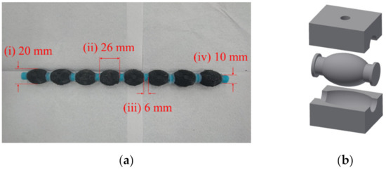
Figure 1.
(a) MAE crawler. (i) Short semi-axis, s1/s2 (rotationally symmetric about long centre axis of the crawler); (ii) Long semi-axis, s3. Ends of the ellipsoid were trimmed so that the real length was rather than 30.6 ; (iii) Connector diameter; (iv) Connector length. (b) Exploded view of 3-part mold used to cast a single ellipsoidal MAE unit. The slurry is injected through the hole at the top.
Each hollow MAE ellipsoid had a long semi-axis s3 of (each ellipsoid was trimmed so that the final semi-axis length became for attaching cylindrical connector), a short, semi-axis of 10 mm, rotationally symmetrical about the long semi axis, and a wall thickness of . The MAE units were sealed and connected together using rigid cylindrical connectors (length = , diameter = ) casted from silicone with significantly higher stiffness (Mold Star 16, Smooth-On) than the ellipsoid units. The adhesive used was Sil-Poxy (Smooth-On). Length of the crawler (excluding the blue connectors at both ends) was .
3. Mechanism of Crawling
When an external magnetic field is applied near an ellipsoidal unit of the MAE crawler, it caused the unit to deform which is the key to the crawler’s locomotionIn this study, peristaltic motion and the caterpillar motion by the fabricated MAE crawler were investigated.
3.1. Peristaltic Motion
Figure 2 illustrates the mechanism for peristaltic locomotion. Two magnetic field sources were positioned above and below the crawler respectively. In this experiment, two permanent magnets were used as the magnetic field source. The magnets were moved along the body of the crawler, from the head to the tail. When the magnets were directly above/below a given section of the crawler, the ellipsoidal MAE units of that section of the crawler were attracted to the magnetic field. The ellipsoidal units actuated due to the magnetic force, widening along the short axis, parallel to the magnetic flux, and shortening along the long axis, perpendicular to the magnetic flux. The tail end of the crawler was pulled forwards by this actuation (in the opposite direction to the motion of the magnets). The number of ellipsoidal units within the area ‘under the magnets depends on the relative size of the magnets. In this experiment, magnets of dimensions were used, meaning a length equivalent to two ellipsoidal units was accommodated between the magnets at one time (Figure 2b–d). As the magnets were moved along the length of the crawler towards the tail end, each ellipsoidal unit was sequentially actuated when exposed to the magnetic field and then relaxed when the magnetic field was released. Due to the restoration force of the elastomer, the units returned to their original shape and the head of the crawler extends forward. The ellipsoidal unit are sequentially exposed to the magnetic field and the deformation propagates from head to tail.
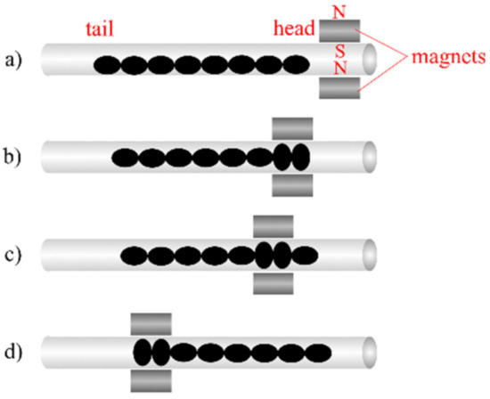
Figure 2.
Mechanism of peristaltic locomotion. (a) The robot in resting state before actuation. (b) The first two spheroid units of the robot are deformed. (c) Ellipsoid units of robot are deformed sequentially as magnets move from head to tail. (d) Robot advances forward due to combined effect of contraction and release of individual units.
The crawler crawls forward by combined effect of the contraction and relaxation of individual ellipsoidal MAE units during the movement of the magnet from the head to tail end of the crawler. Its displacement in one pass of the magnet from head to tail can be estimated by assuming the MAE unit as a perfect ellipsoid with two shorter semi-axes, s1 and s2 of equal length and a longer semi-axis s3 of length . When a unidirectional magnetic field is applied across an ellipsoidal MAE unit along axis s1, the unit deforms, shortening s3 to new length and lengthening s1 to new length . We assume the perimeter of the elliptical cross-section described by and is equal to the perimeter of the original cross section described by and . From the commonly used estimation of ellipse perimeter , we can obtain the following relationship:
The dimensions used in this experiment were and . We assume the maximum value of s1 is equal to the internal radius of the acrylic pipe, therefore and (Equation (1)). In other words, the diameter of the longer semi-axis is shortened by during deformation. The theoretical displacement by the crawler when one ellipsoidal unit undergoes deformation and relaxation is therefore equal to . Since the crawler comprises eight units, the total displacement in one cycle can be estimated as . This estimate does not take tensile strain of the elastomer into account. Therefore, it is likely to be larger than the actual value.
A second estimation was made based on the measured deformation of a single ellipsoid as shown in Figure 3. When exposed to the external magnetic field (which details will be discussed at the beginning of part IV), the length of the longer semi-axis became , which was only shorter than the original length. With eight units, the displacement by the crawler in one cycle can be estimated as .
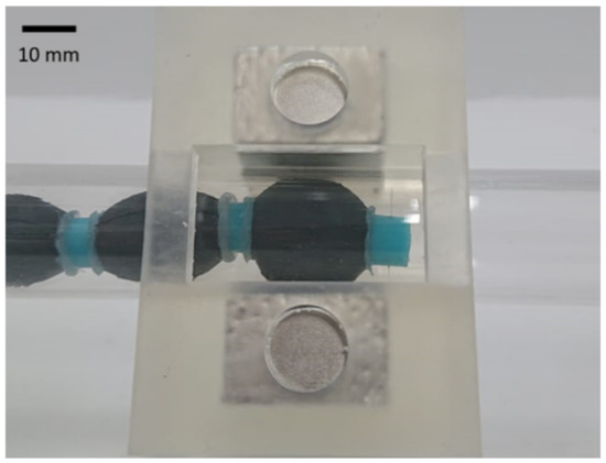
Figure 3.
Deformed ellipsoid under external magnetic field.
3.2. Caterpillar Motion
Figure 4 illustrates the mechanism of caterpillar locomotion. In contrast to peristaltic motion, only one magnetic field source is needed for caterpillar motion and the direction of field movement along the crawler is from the tail to the head. When the field source is directly above an ellipsoidal MAE unit, the unit is lifted up by magnetic force. A “half-wave” is created in the body where the peak is at the lifted unit. As the magnetic field moves forward along the length of the body, the half-wave moves together with the field. Friction plays an important role in the caterpillar locomotion. It is the major force that stops the crawler head from just sliding forward when the magnet moves. It also distinguishes the caterpillar locomotion from magnetic dragging as friction does not favor the crawler motion in magnetic dragging.
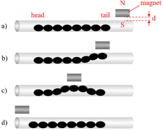
Figure 4.
Mechanism of caterpillar locomotion. (a) The robot in resting state before actuation. (b) The ellipsoid units at the tail of the robot are lifted to form a half-wave. (c) Ellipsoid units of robot are lifted sequentially as the magnet move from tail to head. (d) Robot advances forward due to formation and movement of half-wave from the tail to the head. d is the separation between the magnet and the pipe surface.
To estimate the displacement by the crawler in one magnetic field travelling cycle, we need to first know the characteristics of the half-wave created. For simplicity, we estimate the half-wave as an isosceles triangle (Figure 5).
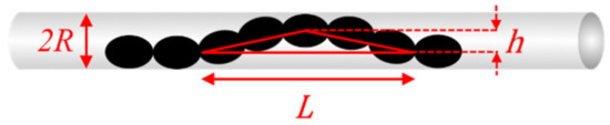
Figure 5.
Estimation of triangle when doing calculations on the half-wave.
Suppose is the height and is the length of the base of the triangle which is equal to the half-wavelength. Then, the difference between the length of the base and the combined length of the other two sides of the triangle is:
Such a difference is also the distance moved forward by the crawler when the half-wave had traveled from the tail to the head. Therefore, is the estimated displacement by the crawler in one cycle. In the case of and (which were obtained empirically), .
In peristaltic locomotion, the deformation of each ellipsoidal unit is limited by the minimum distance between the pipe wall and the crawler, as this distance limits the lengthening of the ellipsoid in the minor axis s1 and consequently the compression in the major axis s3. This distance in turn depends on the inner radius of the pipe . Therefore, the displacement by the crawler in one cycle is limited by and dependent on the number of ellipsoidal units, .
The amplitude can be expressed as . The length of the half-wave created in caterpillar motion also depends on . Since these two half-wave parameters determine the displacement travelled by the crawler in one cycle (Equation (2)), is determined by . In contrast to peristaltic motion, is not a factor in calculating the displacement by the crawler. Using Equations (1) and (2), and assuming the actuated MAE unit widens until it touches the wall of the pipe, the estimated displacement, , travelled by a crawler with ellipsoidal units can be expressed as:
for peristaltic motion and:
for caterpillar motion.
Peristaltic motion depends on the dimensions and number of the ellipsoidal units while the caterpillar motion does not. Instead, it depends on . Therefore, different strategies are needed for different locomotion patterns to increase the locomotion efficiency of the crawler.MAE ellipsoids with larger and smaller , and a pipe with larger are likely to increase the efficiency of peristaltic locomotion as predicted by Equation (3). Similarly, from Equation (4), we can see that larger and smaller are likely more beneficial for caterpillar locomotion. In addition, although the relationship between and have not been studied yet, we expect to be inversely correlated to because the distance between the two ends of a long compliant body initially lying straight on the ground should decrease when its central point is being lifted up. If we differentiate equation 4 with respect to , we get:
which is always less than for a positive . From Equation (5), we can deduce that and are also inversely correlated. Therefore, a pipe with a larger is favorable for caterpillar locomotion. A more systematic study for optimizing crawler parameters is essential for improving its locomotion efficiency. It is planned for future research.
Strength and traveling velocity of the magnetic field also play important roles in the locomotion efficiency. A stronger magnetic field can cause larger deformation of the MAE ellipsoids, hence increase the traveling distance of the crawler using peristaltic locomotion. Traveling velocity of the magnetic field determines the duration of an MAE ellipsoid under the field’s effect. We have done experiments to study the relationships between crawler velocities and magnet velocities in both locomotion mechanisms. The results are presented in the next section.
4. Experimental Methodology
The two locomotion patterns of the crawler were experimentally verified. The experimental set-up is shown in Figure 6. The crawler was placed inside an acrylic pipe which was aligned horizontal. The pipe dimensions were length, internal and external diameters of and respectively. The diameter of the crawler was , therefore, the maximum tensile deformation for the crawler along the shorter semi-axis, s1 was . In this experiment, neodymium permanent magnets (N40, Sangyo Supply, Sendai, Japan), rectangular cuboid with dimensions of were used to produce the magnetic field. The magnetic flux goes through the square surfaces of the magnets, with a flux density of at the surface according to the product data sheet. The polar configuration of the two magnets was in the same pole facing the same direction, resulting in an attractive force between them. To maintain a constant distance between the magnets and the tube throughout the experiment, the magnets were housed inside a 3D-printed case which fitted around the outside of the tube. The magnets were in contact with the outer surface of the pipe to maximize the field strength. When there is one magnet, the magnetic field at the inner surface of the pipe, which was away from the magnet surface, was calculated from the dimensions of the magnet as using the magnetic field equation for rectangular prism permanent magnets [29]. The magnets were moved along the acrylic pipe by the electric linear actuator EC-DS6SAH-500 (Intelligent Actuator Incorporated, Shizuoka, Japan).
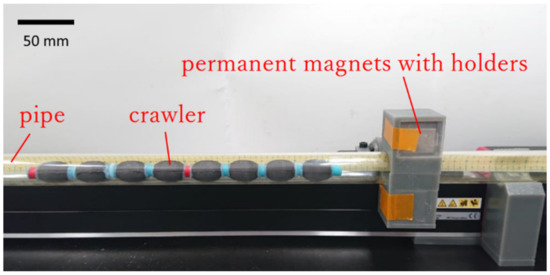
Figure 6.
Experimental set-up.
4.1. Peristaltic Motion
To achieve the peristaltic motion described in the previous section, a pair of permanent magnets were positioned at the top/bottom side of the pipe. The magnets were moved from the head to the tail of the crawler. The experiment was repeated with the pipe aligned vertically.
4.2. Caterpillar Motion
The caterpillar locomotion was investigated with a similar set-up. The only difference is that a single magnet was used this time. The magnets were moved by the linear actuator from the tail to the head of the crawler (the opposite direction to that used for peristaltic motion).
Videos of the experiments were recorded in 60 frames per second and were examined to obtain the displacement of the crawler during the magnet movement.
The force required to form a half-wave in the caterpillar locomotion pattern was estimated by attaching a force gauge to the body of the crawler, and measuring the lifting force required to form a half-wave like the one in Figure 5.
5. Results and Discussion
5.1. Peristaltic Motion
The crawler moved in an opposite direction to the magnet movement as expected. Figure 7 shows the sequential screenshots during one magnetic cycle in the experiment. The locomotion mechanism as proposed in Figure 2 is confirmed by the experiment.
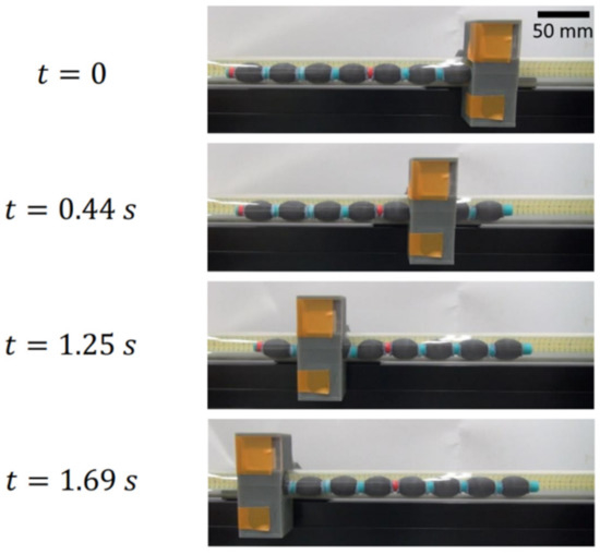
Figure 7.
Peristaltic locomotion performed by the fabricated MAE crawler.
Figure 8a shows the relationship between the magnet movement velocity and the displacement by the crawler in one cycle. The experiment was carried out with 10 different magnet velocities ranging from to mm/s. Three cycles were carried out for each speed and thus 30 cycles were analyzed in total. The maximum displacement obtained during a single cycle was ( of the crawler’s length) which was very close to the estimated value calculated based on the constant ellipsoidal perimeter assumption in section IIA. On the other hand, the maximum displacement was larger than the second estimation of in section IIA, which was calculated based on the experimentally measured deformation of a single ellipsoidal unit. Nevertheless, both the estimation using constant ellipsoidal perimeter assumption and the estimation based on measured ellipsoid deformation were quite close to the experimental value. The discrepancy observed between the experimental value and both estimations might be due to the fact that when a MAE ellipsoid is deformed under an external magnetic field, its central axis is lifted up. This pulls up the ellipsoids next to it, and crawler moves by an extra distance horizontally. As a result, the experimental values are closer than expected to the estimation using constant ellipsoidal perimeter assumption.
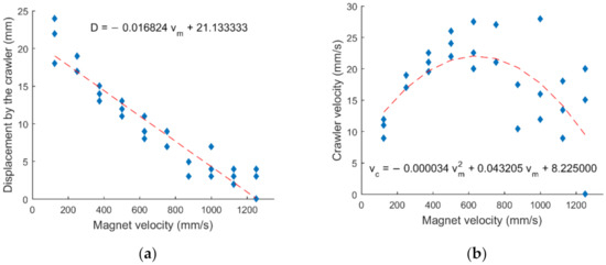
Figure 8.
Scatter plot of (a) the displacement by the MAE crawler in one cycle against the average velocity of the magnet, and (b) crawler velocity against the average velocity of the magnet in horizontal pipe in the case of peristaltic locomotion. Due to repeated data points, there are less than 3 observable data points for certain velocities.
The relationship between the displacement by the crawler in a single cycle and the traveling velocity of magnet is seemingly an inverse linear relationship, which is within expectation as the rate of change of magnetic field at any position is higher while the response time by MAE remains the same. As a result, the MAE ellipsoid may not reach full deformation during the period it is exposed to the magnetic field. The crawler should therefore move by a smaller distance when the magnet moves faster.
The average crawler velocity was calculated from the crawler displacement and the period of one stroke of the magnet travelling from one end to the other of the crawler. The crawler velocity versus magnet movement velocity was plotted in Figure 8b. We can see from the graph that the crawler velocity increased with magnet movement velocity linearly at first but started to drop when the magnet velocity exceeded . This could be the point around which the crawler velocity reached the maximum value as responsiveness of the MAE material start to limit the positive effect from the fast-changing magnetic field. Also, deviation in crawler velocities was observed to increase with the magnet movement velocity, which could be due to increasingly unsteady magnet velocities and possible inhomogeneity of the ellipsoidal MAE units.
The experiment was repeated with increased gap between the magnets and the pipe surface by such that the magnetic flux densities at the inner surface of the pipe for one magnet were weaker than before () [29]. However, the crawler barely moved under such configuration. This shows that a strong magnetic field is crucial for peristalsis.
The experiment was repeated with the pipe aligned vertically, as shown in Figure 9. The results of crawler distance and velocity are shown in Figure 10. Three cycles were carried out for each of the five different magnet velocities ranging from to , providing 15 data points in total. The crawler had a maximum vertical displacement of ( of the crawler’s length) which was close to the maximum displacement obtained in the horizontal case. Similar to the horizontal case, we can observe from Figure 10a that the vertical case still showed an inverse relationship between the crawler displacement and the magnet velocity. However, a weaker trend was observed from the data. The weak relationship between the crawler distance and the magnet velocity can be explained by inhomogeneity of the ellipsoidal MAE units. It can also be explained by inhomogeneity of the crawler’s initial configuration this time. As the tube was placed vertically, the crawler’s lower part bent due to its own weight, and this might contribute to the error. Despite this issue, the experiment showed that the peristaltic locomotion by the crawler also worked in vertical pipes. As a side note, the displacements by the crawler in the vertical case were generally less than those in the horizontal case under the same magnet speed. A reason that contributed to such discrepancy could be the fact that the crawler sometimes buckled due to its own weight after the permanent magnet passed, turning itself into a caterpillar form similar to Figure 5.
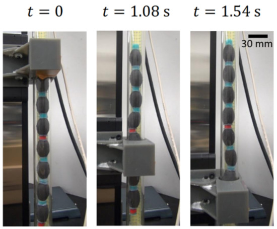
Figure 9.
Peristaltic locomotion performed by the fabricated MAE crawler in a vertical pipe.
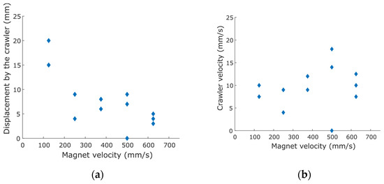
Figure 10.
Scatter plot of (a) the displacement by the MAE crawler in one cycle against the average velocity of the magnet, and (b) crawler velocity against the average velocity of the magnet in vertical pipe in the case of peristaltic locomotion. Due to repeated data points, there are less than 3 observable data points for certain velocities.
5.2. Caterpillar Motion
In the caterpillar motion experiments, the crawler moved forward as the magnet was moved from the tail to the head of the crawler as depicted in Figure 11 and Figure 12 shows the average magnet movement velocity and the displacement by the crawler after five magnetic cycles, under the conditions of , and magnet separation. 15 experiments were done with three for each of the five magnet velocities ranging from to . Unlike peristaltic locomotion, the displacement by the crawler was near constant under different magnet movement velocity, as shown in Figure 12a. The mean displacement per cycle, with , and magnet separation from the tube, were , and (About to of the crawler’s length) respectively. The experimental values were close to the estimated value of obtained from Equation (2). From the results, displacement by the crawler using caterpillar crawling is less dependent on magnet movement velocity than peristaltic locomotion. This is likely because the dynamic response of the MAE, lifting by magnetic force, is fast compared to the viscoelastic behavior of the elastomer on which the peristaltic motion is dependent. The velocity of the crawler was calculated and plotted in Figure 12b. They all showed a linear relationship with the magnet velocity since the distance traveled by the crawler was constant while the duration the crawler was exposed to the magnetic field decreased with increased magnet velocity. The highest crawler velocities for , and magnet separation, when the magnet velocity was , were , , , respectively. It is clear that the crawler moved forward with an increased speed when the magnetic field strength decreased. This is because a weaker magnetic field allows the MAE ellipsoid to escape more easily and thus a smoother progression of the caterpillar half wave can be achieved. This and the time for lifting up the ellipsoidal MAE units are the two major factors in deciding the optimum magnetic field for the caterpillar locomotion, which should be investigated in the future.
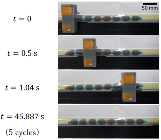
Figure 11.
Caterpillar locomotion performed by the fabricated MAE crawling robot. The time for the magnet to move back to its initial position is included in the total time.
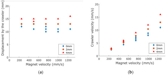
Figure 12.
Scatter plot of (a) the displacement by the MAE crawler in 5 cycles against the average velocity of the magnet, and (b) average crawler velocity against the average velocity of the magnet in horizontal pipe with 0 mm, 2 mm and 4 mm magnet distance from the pipe in the case of caterpillar locomotion. Due to repeated data points, there are less than 3 observable data points for certain velocities.
Since the caterpillar locomotion relies on the friction between the crawler and inner wall of the tube as explained in the mechanisms section, experiment with a vertical tube where there is negligible wall friction was not carried out.
Comparing the crawler velocities in Figure 8b and Figure 12b, we can see that the peristaltic motion is superior to the caterpillar motion in terms of crawler velocity traveled in a narrow pipe. On the other hand, the caterpillar motion gave a more consistent performance. It is also advantageous over the peristaltic motion in terms of force required for locomotion. The total mass of the MAE crawler was measured as , with each ellipsoidal unit weighing between and g. During peristaltic motion, when an ellipsoidal unit contracts and relaxes, it pulls the units behind it and pushes the units in front of it. The maximum force required for pushing or pulling, which occurs at the head and the tail of the crawler, can be approximated as the friction against the whole crawler, which is usually a fraction of . This maximum force is only required when the magnet is at either end of the crawler. When the magnet is at the middle along the crawler’s body, the pushing and pulling force is about the same which is the friction against half of the crawler. Therefore, peristaltic motion can move a heavier crawler than simple magnetic dragging. From experiments, we can see that the portion of the crawler just next to the magnet is actually lifted and therefore the friction against locomotion is even lower. For caterpillar motion, the force required is the lifting force needed to form the half-wave shape, which is comprised of about five ellipsoidal units. The force required for forming a half-wave with amplitude was measured as , which is about half of the estimated maximum force needed in peristaltic motion under a conservative assumption of friction coefficient being 1. Besides, judging from Equations (3) and (4), we can anticipate that as increases, the maximum force required for peristaltic motion will increase proportionally while the force for caterpillar motion will remain unchanged. Therefore, peristaltic motion is favored for higher speed and caterpillar motion excels when the magnetic force input is limited. Moreover, caterpillar motion requires only one magnetic field source, whereas peristaltic motion requires a pair of symmetric magnetic field sources.
5.3. Comparison to Other Soft Magnetic Robots
Table 1 gives a brief comparison among different soft magnetic robots developed. From the table, we can see that higher velocity can be achieved by smaller robots. This can be explained by the fact that a smaller body implies lighter weight and less force required to move. It also allows the use of electromagnets as the magnetic field source which can switch their field strength and polarity in high frequency despite being weaker than permanent magnets. Nevertheless, our crawler still gave a moderate velocity despite its large body. Moreover, using iron powder and not needing pre-magnetization makes our crawler low-cost and easy to fabricate.

Table 1.
Comparison of different reported soft magnetic robots. Although the locomotion types are only classified into two catergories, each of the robots mentioned in this table moves in a quite distinctive manner, which also affects its maximum velocity.
6. Conclusions
In this paper, we report the fabrication of a cm-scale crawler made of magneto-active elastomer. The crawler is light and durable. It has a soft and simple structure which allows easy fabrication and miniaturization. Through experiments, the crawler was shown to be capable of peristaltic and caterpillar locomotion under a moving applied magnetic field. This is the first time the peristaltic locomotion pattern was demonstrated using MAE actuators. Respective advantages of the two locomotion patterns and their suitability for different applications are discussed in this paper. The crawler has the potential to address the problems faced by other crawlers employing similar locomotion mechanisms by having low mass and complexity of architecture, structural compliance and materials with low environmental impact. Compared to conventional snake robots, the MAE crawler has a much simpler structure and softer body. The concept of applying external magnetic field enables wireless control of the crawler. Even though it is possible that the magnetic source is tethered in real application, it is important that the crawler is not as being tethered in complex environments and confined spaces might hinder the movement of the robot.
The magnetic field strength acting on a magnetizable body varies steeply and inversely with distance from the source. This must be taken into consideration when designing applications around this type of technology. A possible solution to this is to increase the surface field strength of the magnetic sources used to actuate the robots.
The concept of applying MAE actuator in locomotion benefits a wide range of fields such as narrow space exploration and in vivo medical applications. The hollow MAE actuators mentioned in this paper can help realizing robots for these applications with its light weight and responsiveness. In the future, we will work on optimizing the crawler design. We will carry out simulations and experiments with different crawler sizes, magnetic field strengths and pipe sizes to understand the significance of these parameters. We will refine the crawler and experimental design to minimize the variance in locomotion performance especially in a vertical pipe. We will further explore the possible applications for crawler. The crawler’s ability to traverse a bend in a pipe and to carry a payload is also a possible topic for investigation. Besides, other applications utilizing these hollow MAE actuators will be investigated too.
Author Contributions
Conceptualization, T.L.Y.; Investigation, T.L.Y.; Methodology, T.L.Y.; Project administration, H.P.; Supervision, H.P. and F.M.; Validation, T.L.Y.; Writing—original draft, T.L.Y.; Writing—review & editing, T.L.Y., H.P. and F.M. All authors have read and agreed to the published version of the manuscript.
Funding
This research received no external funding.
Conflicts of Interest
The authors declare no conflict of interest.
References
- Ambe, Y.; Matsuno, F. Leg-grope-walk—Walking strategy on weak and irregular slopes for a quadruped robot by force distribution. In Proceedings of the 2012 IEEE/RSJ International Conference on Intelligent Robots and Systems, Algarve, Portugal, 7–12 October 2012; pp. 1840–1845. [Google Scholar]
- Hirose, S.; Mori, M. Biologically inspired snake-like robots. In Proceedings of the 2004 IEEE International Conference on Robotics and Biomimetics, Shenyang, China, 22–26 August 2004; pp. 1–7. [Google Scholar]
- Saga, N.; Nakamura, T. Development of a peristaltic crawling robot using magnetic fluid on the basis of the locomotion mechanism of the earthworm. Smart Mater. Struct. 2004, 13, 566. [Google Scholar] [CrossRef]
- Trimmer, B.A.; Takesian, A.E.; Sweet, B.M.; Rogers, C.B.; Hake, D.C.; Rogers, D.J. Caterpillar locomotion: A new model for soft-bodied climbing and burrowing robots. In Proceedings of the 7th International Symposium on Technology and the Mine Problem, Monterey, CA, USA, 2–5 May 2006; pp. 1–10. [Google Scholar]
- Seok, S.; Onal, C.D.; Wood, R.; Rus, D.; Kim, S. Peristaltic locomotion with antagonistic actuators in soft robotics. In Proceedings of the 2010 IEEE International Conference on Robotics and Automation, Anchorage, Alaska, 3–8 May 2010; pp. 1228–1233. [Google Scholar]
- Trimmer, B.; Issberner, J. Kinematics of soft-bodied, legged locomotion in Manduca sexta larvae. Biol. Bull. 2007, 212, 130–142. [Google Scholar] [CrossRef] [PubMed]
- Saga, N.; Seto, T.; Takanashi, H.; Saito, N. Development of a peristaltic crawling robot using planar link mechanisms. IEEJ Trans. Electr. Electron. Eng. 2008, 3, 72–78. [Google Scholar] [CrossRef]
- Nakamura, T.; Kato, T.; Iwanaga, T.; Muranaka, Y. Peristaltic crawling robot based on the locomotion mechanism of earthworms. IFAC Proc. 2006, 39, 139–144. [Google Scholar] [CrossRef]
- Kishi, T.; Ikeuchi, M.; Nakamura, T. Development of a Peristaltic Crawling Inspection Robot for Half-Inch Pipes Using Pneumatic Artificial Muscles. SICE J. Control Meas. Syst. Integr. 2015, 8, 256–264. [Google Scholar] [CrossRef]
- Saga, N.; Tesen, S.; Sato, T.; Nagase, J.-Y. Acquisition of earthworm-like movement patterns of many-segmented peristaltic crawling robots. Int. J. Adv. Robot. Syst. 2016, 13, 1729881416657740. [Google Scholar] [CrossRef]
- Tanise, Y.; Kishi, T.; Yamazaki, S.; Yamada, Y.; Nakamura, T. High-speed response of the pneumatic actuator used in a peristaltic crawling robot inspecting long-distance gas pipes. In Proceedings of the 2016 IEEE International Conference on Advanced Intelligent Mechatronics (AIM), Banff, AB, Canada, 12–15 July 2016; pp. 1234–1239. [Google Scholar]
- Zhang, H.; Gonzalez-Gomez, J.; Zhang, J. A new application of modular robots on analysis of caterpillar-like locomotion. In Proceedings of the 2009 IEEE International Conference on Mechatronics, Málaga, Spain, 14–17 April 2009; pp. 1–6. [Google Scholar]
- Umedachi, T.; Trimmer, B.A. Autonomous decentralized control for soft-bodied caterpillar-like modular robot exploiting large and continuum deformation. In Proceedings of the 2016 IEEE/RSJ International Conference on Intelligent Robots and Systems (IROS), Daejeon, Korea, 9–14 October 2016; pp. 292–297. [Google Scholar]
- Zou, J.; Lin, Y.; Ji, C.; Yang, H. A reconfigurable omnidirectional soft robot based on caterpillar locomotion. Soft Robot. 2018, 5, 164–174. [Google Scholar] [CrossRef]
- Diermeier, A.; Sindersberger, D.; Krenkel, L.; Rosell, X.; Monkman, G. Controllable Magnetoactive Polymer Conduit. Open Mech. Eng. J. 2018, 12, 192–200. [Google Scholar] [CrossRef]
- Raikher, Y.L.; Stolbov, O. Magnetodeformational effect in ferrogel samples. J. Magn. Magn. Mater. 2003, 258, 477–479. [Google Scholar] [CrossRef]
- Raikher, Y.L.; Stolbov, O. Magnetodeformational effect in ferrogel objects. J. Magn. Magn. Mater. 2005, 289, 62–65. [Google Scholar] [CrossRef]
- Böse, H. Viscoelastic properties of silicone-based magnetorheological elastomers. Int. J. Mod. Phys. B 2007, 21, 4790–4797. [Google Scholar] [CrossRef]
- Makarova, L.A.; Alekhina, Y.A.; Rusakova, T.S.; Perov, N.S. Tunable properties of magnetoactive elastomers for biomedical applications. Phys. Procedia 2016, 82, 38–45. [Google Scholar] [CrossRef]
- Böse, H.; Rabindranath, R.; Ehrlich, J. Soft magnetorheological elastomers as new actuators for valves. J. Intell. Mater. Syst. Struct. 2012, 23, 989–994. [Google Scholar] [CrossRef]
- Kashima, S.; Miyasaka, F.; Hirata, K. Novel soft actuator using magnetorheological elastomer. IEEE Trans. Magn. 2012, 48, 1649–1652. [Google Scholar] [CrossRef]
- Zimmermann, K.; Naletova, V.A.; Zeidis, I.; Turkov, V.A.; Kolev, E.; Lukashevich, M.V.; Stepanov, G.V. A deformable magnetizable worm in a magnetic field—A prototype of a mobile crawling robot. J. Magn. Magn. Mater. 2007, 311, 450–453. [Google Scholar] [CrossRef]
- Zimmermann, K.; Naletova, V.; Zeidis, I.; Turkov, V.; Kolev, E.; Kalmykov, S. Calculation of a magnetizable worm deformation in a magnetic field. Magnetohydrodynamics 2008, 44, 143–148. [Google Scholar] [CrossRef]
- Zimmermann, K.; Naletova, V.; Zeidis, I.; Böhm, V.; Kolev, E. Modelling of locomotion systems using deformable magnetizable media. J. Phys. Condens. Matter 2006, 18, S2973. [Google Scholar] [CrossRef]
- Diller, E.; Zhuang, J.; Lum, G.Z.; Edwards, M.R.; Sitti, M. Continuously distributed magnetization profile for millimeter-scale elastomeric undulatory swimming. Appl. Phys. Lett. 2014, 104, 174101. [Google Scholar] [CrossRef]
- Lum, G.Z.; Ye, Z.; Dong, X.; Marvi, H.; Erin, O.; Hu, W.; Sitti, M. Shape-programmable magnetic soft matter. Proc. Natl. Acad. Sci. USA 2016, 113, E6007–E6015. [Google Scholar] [CrossRef]
- Hu, W.; Lum, G.Z.; Mastrangeli, M.; Sitti, M. Small-scale soft-bodied robot with multimodal locomotion. Nature 2018, 554, 81–85. [Google Scholar] [CrossRef]
- Venkiteswaran, V.K.; Samaniego, L.F.P.; Sikorski, J.; Misra, S. Bio-Inspired Terrestrial Motion of Magnetic Soft Millirobots. IEEE Robot. Autom. Lett. 2019, 4, 1753–1759. [Google Scholar] [CrossRef]
- Camacho, J.M.; Sosa, V. Alternative method to calculate the magnetic field of permanent magnets with azimuthal symmetry. Rev. Mex. De Física E 2013, 59, 8–17. [Google Scholar]
- Lu, H.; Zhang, M.; Yang, Y.; Huang, Q.; Fukuda, T.; Wang, Z.; Shen, Y. A bioinspired multilegged soft millirobot that functions in both dry and wet conditions. Nat. Commun. 2018, 9, 1–7. [Google Scholar] [CrossRef] [PubMed]
- Gu, H.; Boehler, Q.; Cui, H.; Secchi, E.; Savorana, G.; de Marco, C.; Gervasoni, S.; Peyron, Q.; Huang, T.Y.; Pane, S.; et al. Magnetic cilia carpets with programmable metachronal waves. Nat. Commun. 2020, 11, 1–10. [Google Scholar] [CrossRef]


Publisher’s Note: MDPI stays neutral with regard to jurisdictional claims in published maps and institutional affiliations. |
© 2021 by the authors. Licensee MDPI, Basel, Switzerland. This article is an open access article distributed under the terms and conditions of the Creative Commons Attribution (CC BY) license (https://creativecommons.org/licenses/by/4.0/).