Article

Contactless Picking of Objects Using an Acoustic Gripper †

Power Electronic Systems Laboratory, ETH Zurich, Switzerland, Physikstrasse 3, 8092 Zurich, Switzerland
*
Author to whom correspondence should be addressed.
This paper is an extended version of our paper published in the 1st International Electronic Conference on Actuator Technology: Materials, Devices and Applications (IeCAT), 23–27 November 2020.
Actuators 2021, 10(4), 70; https://doi.org/10.3390/act10040070
Submission received: 31 January 2021 / Revised: 24 March 2021 / Accepted: 26 March 2021 / Published: 31 March 2021

Abstract

:
Acoustic levitation forces can be used to manipulate small objects and liquids without mechanical contact or contamination. This work presents analytical models based on which concepts for the controlled insertion of objects into the acoustic field are developed. This is essential for the use of acoustic levitators as contactless robotic grippers. Three prototypes of such grippers are implemented and used to experimentally verify the lifting of objects into an acoustic pressure field. Lifting of high-density objects ( ρ > 7 g/cm 3 ) from acoustically transparent surfaces is demonstrated using a double-sided acoustic gripper that generates standing acoustic waves with dynamically adjustable acoustic power. A combination of multiple acoustic traps is used to lift lower density objects ( ρ 0.25   g / cm 3 ) from acoustically reflective surfaces using a single-sided arrangement. Furthermore, a method that uses standing acoustic waves and thin reflectors to lift medium-density objects ( ρ 1   g / cm 3 ) from acoustically reflective surfaces is presented. The provided results open up new possibilities for using acoustic levitation in robotic grippers, which has the potential to be applied in a variety of industrial use cases.

1. Introduction

Trapping of objects by means of acoustic forces is used in various areas such as chemistry [1], bioreactors [2,3], blood analysis [4], the study of organisms in microgravity [2,5], control of nanomaterial self-assembly [6], containerless processing [7,8,9], and to study droplet dynamics [10,11].
The main advantage of acoustic levitation over other levitation methods is its independence from the material properties of the object. Magnetic levitation requires a ferromagnetic or permanent magnet object [12] and electrostatic levitation requires an electrically conductive or a charged object [13]. Optical levitation is only suitable for very small objects and dissipates large amounts of energy into the object [14]. Furthermore, acoustic levitation facilitates passively stable levitation.
It is known that standing acoustic waves generated by a single source can be used to levitate objects [15,16,17]. Recently, new concepts have been developed that use transducer arrays instead of a single or few transducers and can additionally manipulate levitated objects [18,19]. To enable such manipulations, a system capable of adjusting the pressure field by exciting the transducers individually is required [20,21].
Thus, objects of any material can be transported and positioned without mechanical contact, i.e., with low stress on the object and without contamination. However, the transport range is limited to the range of the acoustic field. To increase this range, the device that generates the acoustic field can be mounted to a robot arm as a gripper, as shown in Figure 1 and Figure 2 [22].
For implementing an acoustic gripper, it is necessary to automatically insert objects into the acoustic field in a controlled manner [23]. This work demonstrates acoustic grippers for different boundary conditions, namely, for high-density objects placed on acoustically transparent surfaces and low- or medium-density objects placed on reflective surfaces.

2. Acoustic Levitation Using Transducer Arrays

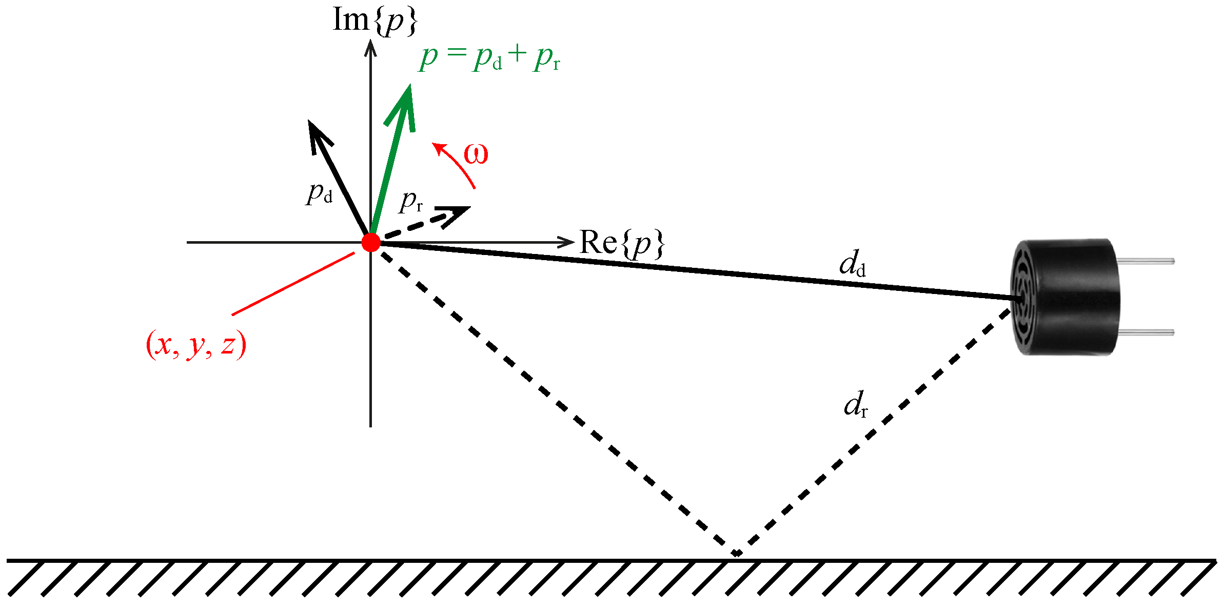
2.1. Pressure and Force Generation

An array of piezoelectric transducers of type MSO-P1040H07T is used to generate the acoustic field. An acoustic pressure acts on the surface of an object in the acoustic field and is capable of counteracting the gravitational force, which results in levitation of the object. The acoustic pressure generated by the jth transducer of the array at a given point in space is calculated as
p j = e i ϕ V RMS P 0 J 0 ( k r sin θ ) d e i k d ,
where ϕ , V RMS , P 0 , J 0 , d, θ , r, and k = 2 π f / c 0 denote the phase of the transducer excitation signal, the RMS value of the excitation signal, a factor depending on the transducer type, the Bessel function of order zero, the distance of the considered point to the transducer, the beam angle, the radius of the transducer, and the wave number, respectively [18]. In the formula for the wave number, f and c 0 denote the excitation frequency and the speed of sound in the considered medium (air), respectively. The Gor’kov potential is a potential function that describes the acoustic forces exerted on a spherical particle with radius a much smaller than the acoustic wavelength λ . It is calculated by the superposition of an incident wave and a wave reflected from the surface of the levitated object [24,25]. According to the Gor’kov potential, the acoustic forces acting on a suspended particle scale proportionally to the square of the pressure magnitude, which is in turn proportional to the square of the transducer excitation voltage magnitude V, yielding
F | p | 2 V 2 .

2.2. Transducer Characterization

The peak pressure value generated by a piezoelectric transducer is proportional to the deflection of its vibrating element. The deflection is measured in the x direction as shown in Figure 3a and depends on the charge stored in the piezoelectric element [26]. Consequently, the current flowing through the piezoelectric element is the relevant quantity regarding pressure generation. The corresponding equivalent circuit based on a Butterworth-Van Dyke (BVD) model [27] is shown in Figure 3b. It has no significant effect on the resulting pressure whether a square wave or sinusoidal voltage signal is applied to the transducers, since the frequency-dependent impedance of the transducers, which is shown in Figure 3c, suppresses higher order harmonics.
The relation between the 40 kHz component of the applied voltage V 40 and the resulting peak pressure p ^ is given by
p ^ v ^ x ^ Q ^ i ^ = V 40 Z 40 ,
where v, Q, i, and Z 40 denote the particle velocity of the sound wave, the charge stored in the transducer, the current flowing through the transducer, and the impedance of the transducer at 40 kHz, respectively. The hat notation refers to the peak values of these quantities. The phase and magnitude of the pressure are modified by adjusting the phase and duty cycle of the transducer excitation signal, respectively. By providing an individual excitation signal for each transducer, it is possible to adjust the acoustic power output and phase of each transducer individually. The transducers are arranged in arrays of various shapes [28,29,30,31,32,33,34] and held in place by means of a 3D-printed holder.

2.3. Acoustic Traps

To achieve a pressure distribution that facilitates levitation of an object in free space, the phase for each transducer has to be chosen such that the pressures generated by the individual transducers constructively superimpose at a focal point that coincides with the desired levitation position. This is achieved by calculating the phases of the individual excitation signals as
φ = P 0 d d e i 2 π f d d c 0 + R P 0 d r e i 2 π f d r c 0 ,
where the reflection coefficient of an acoustically transparent surface in the acoustic field is R = 0 [18]. The factor is P 0 = 0.26 Pa · m / V RMS for the transducers used in this work [35]. Further, d d and d r denote the distance between the transducer and the focal point for the direct and reflected acoustic wave (see Figure 4), respectively. An acoustic trap is generated by adding a phase signature, which depends on the type of trap, to the phases that are used to generate the focal point [18,36]. In this work, mainly twin traps are used to levitate objects. These are generated by applying a phase shift of 180 to one half of the transducers in an array. Separating the transducers of the array by a horizontal plane results in a trap subsequently referred to as a horizontal twin trap (HTT). Separating the two halves by a vertical plane accordingly results in a vertical twin trap (VTT).
If an acoustically reflective surface is present within the acoustic field, the pressure generated by a single transducer at a point contains an additional component caused by the reflected wave ( R 0 ) [37,38]. The total pressure oscillation has the same frequency as the pressure oscillation without the reflection, but the phase and magnitude are different. This can be illustrated by a pointer diagram, as shown in Figure 4. If the direct pressure component p d is constructively superimposed with the reflected pressure component p r , a higher pressure amplitude is achieved. Due to the change in phase, the control has to be adjusted according to Equation (4) with R set to the appropriate value. If the transducer arrangement is shifted relative to the reflecting surface, the influence of the reflected wave on the phase of p changes, which has to be taken into account by the control.
Using the reflection of sound waves at a surface, a standing wave can be formed between the transducers and the surface by focusing the acoustic pressure on the surface. The distance between the oscillating elements of the transducers and the reflecting surface should be a multiple of λ / 2 to achieve a high pressure magnitude [39,40].

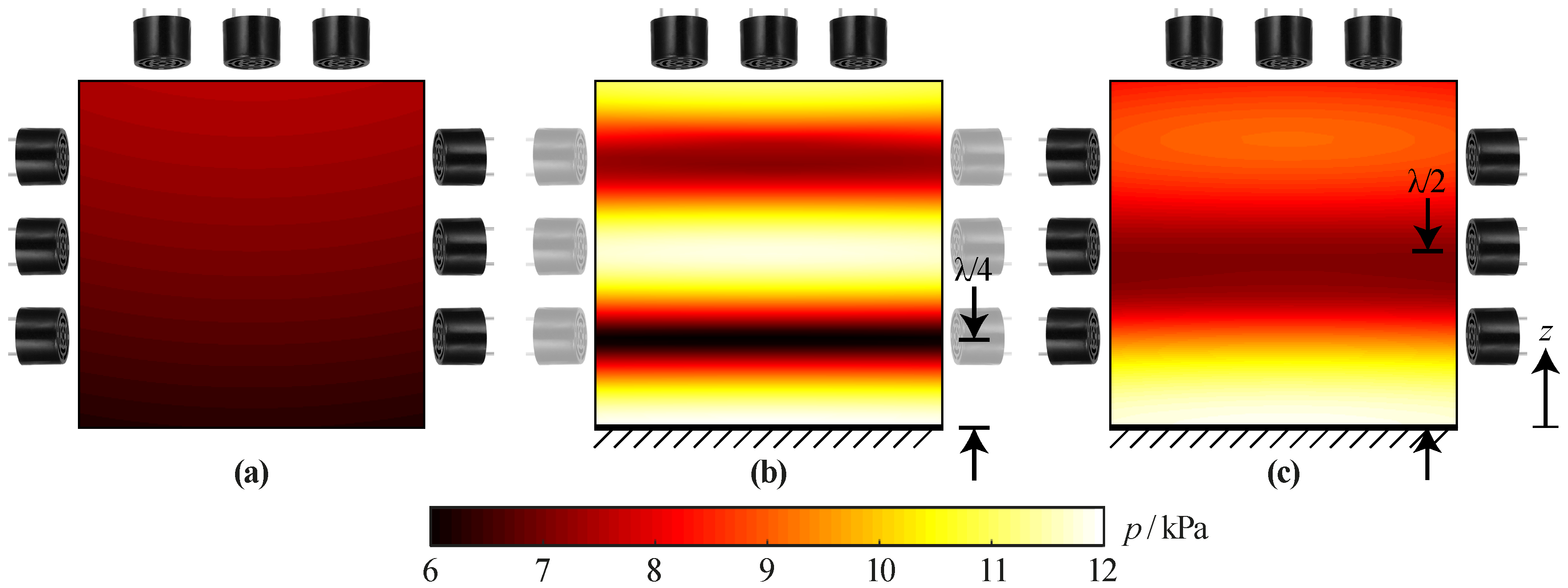
2.4. Distribution of the Maximum Attainable Pressure

A distribution of the maximum attainable pressure (DMAP) describes the distribution that is based on the assumption of a constructive superposition of the pressure from all acoustic sources at each point in space. It is calculated for each point by
M ( x , y , z ) = j V RMS P 0 J 0 ( k r sin θ d , j ) d d , j + R J 0 ( k r sin θ r , j ) d r , j ,
where θ d , j , θ r , j , d d , j , and d r , j denote the beam angle of the direct path, the beam angle of the reflected path, the distance of the direct path between the considered point in space ( x , y , z ) and the transducer, and the distance of the reflected path between ( x , y , z ) and the transducer for the jth transducer, respectively. In environments without reflective surfaces, the DMAP is approximately constant, i.e., the attainable pressure is approximately the same at each point in space, as shown in Figure 5a. This means that it is possible to focus the pressure at each point.

3. Experimental Setup

3.1. Transducer Arrays

Three different transducer arrangements (arrays) are used in this work, namely, as follows:
  • A double-sided array consisting of two pole caps of a sphere with a diameter d = 42   mm , each equipped with 36 transducers arranged in three rings of 6, 12, and 18 transducers. All transducers are oriented such that they point towards the center of the sphere. This arrangement is shown in Figure 1.
  • A cylindrical single-sided array with a height h = 40   mm , an inner diameter d i = 70   mm , and an outer diameter d o = 88   mm , as depicted in Figure 2. Three rings of 6, 12, and 18 vertically oriented transducers are located at the horizontal top face of the arrangement. On the side walls of the cylinder, three rings of 20 horizontally oriented transducers each are located.
  • A reflector array consisting of one half of the double-sided array and an additional thin reflector, which can be moved relative to the transducers. Depending on the application, a movable second half of the double-sided array is added.
The holders of the transducers and the reflector were 3D printed.

3.2. Control System

The position of the object is determined by open-loop control for all arrangements. The phase and amplitude of the transducer excitation signals are calculated depending on the orientation of the acoustic trap, the position of the levitating object relative to the gripper, and the gripper environment, as described in Section 2.3. The corresponding logic signals are generated by a field programmable gate array (FPGA). For the 72, 96, and 36 logic signals required for the double-sided, single-sided, and reflector array, respectively, resolutions of 0 . 5 and ≈1% are achieved for the phase and duty cycle, respectively. The logic signals are amplified by gate driver integrated circuits (ICs) and applied to the transducers. The duty cycle and the phase are calculated on a PC for each transducer and transmitted to the FPGA via a universal asynchronous receiver transmitter (UART) interface.

4. Automated Insertion

The procedure for automatically inserting an object into the acoustic field depends on the properties of the object and its environment. The higher the density of the object and the lower the transmission coefficient of the surface on which the object is located, the more difficult it is to lift the object off the surface.
For a sufficiently large transmission coefficient T of the surface ( T > 0.5 ) and sufficient space on both sides of the surface, the double-sided arrangement, capable of generating high forces in the vertical direction, can be used. Such surfaces are subsequently referred to as acoustically transparent. If the transmission coefficient is low ( T < 0.5 ), the surface is referred to as acoustically reflective and the single-sided or reflector array has to be used. Procedures that facilitate stable and smooth lifting of objects from acoustically transparent and reflective surfaces are presented below.

4.1. Acoustically Transparent Surface

If the object is located on an acoustically transparent surface, the double-sided array is moved close to the object to be picked in the turned-off state. The transducers are then controlled such that the object is located in an acoustic trap. Subsequently, the acoustic power is increased.
The control is identical to that used for levitating the object at the position of the acoustic trap. The influence of the surface on the control can be neglected. By adjusting the control, the pressure field is manipulated such that the object moves in the vertical direction and, afterwards, the arrangement is moved away from the surface. Alternatively, if there are no objects that restrict the vertical movement of the gripper, the arrangement can be moved vertically without prior adjustment of the control.
With this method, picking objects with a density of ρ > 7   g / cm 3 has been demonstrated. In order to improve the repeatability of the process, the acoustic power can be increased continuously during the power-on process, such that no sudden forces are exerted on the object.

4.2. Acoustically Reflective Surface

Picking an object from an acoustically reflective surface is more challenging than picking it from an acoustically transparent surface. The reflection of a wave at a surface does not cause a phase shift. If the incident wave arrives perpendicular to the surface, the superposition between the incident wave p i and the reflected wave p r causes a pressure minimum to be formed at a distance of λ / 4 from the surface, as outlined by Equations (6)–(8) [39,40].
p i ( t , z ) = A sin ω t 2 π z λ .
p r ( t , z ) = A sin ω t + 2 π z λ .
p i ( t , λ / 4 ) + p r ( t , λ / 4 ) = A sin ω t π / 2 + A sin ω t + π / 2 = 0 .
If the acoustic sources are located far away from the surface, the acoustic waves are perpendicularly incident upon the surface. The DMAP for the transducers arranged at the horizontal top of the single-sided arrangement, which are placed at a distance of 3.5 λ from the reflective surface, is shown in Figure 5b. Due to the pressure minimum being formed at z = λ / 4 above the reflective surface, it is impossible to focus the pressure around this location, which would be necessary to generate a twin trap.
If the transducers are located closer to the surface, the distance at which destructive superposition occurs deviates from λ / 4 and the minimum of the DMAP is attenuated. This is shown for the single-sided arrangement in Figure 5c. With this arrangement, it is possible to focus the pressure for z λ / 2 . Therefore, a VTT can be generated at z = λ / 2 , as shown in Figure 6b. The generated forces pull the object into this trap, if their vertical component exceeds the gravitational force. This is the case at z = λ / 4 for all objects that can be lifted with this arrangement, as shown in Figure 7.
By forming a standing wave between the transducers and the reflective surface, it is possible to levitate objects in a stable manner at z λ / 4 , however, without the possibility to move the object vertically due to the minimum of the DMAP at this location. Nevertheless, it is possible to switch from a standing wave to a VTT located at z = λ / 2 that pulls the object upwards. Taking the reflections at the surface into account, the control can be adjusted such that the object is moved away from the surface until reflections become negligible and the array can be moved away from the surface without further adjustments of the control. An array that is capable of generating the corresponding pressure distributions requires vertically oriented transducers to generate a standing wave and horizontally oriented transducers to generate a VTT. The resulting forces and force potentials during the process are shown in Figure 6 and Figure 7 for the single-sided array.
To perform the picking process in a continuous fashion, the power of the vertically oriented transducers is first increased continuously, raising the object smoothly to z = λ / 4 . Subsequently, using stepwise phase changes, the standing wave is altered to a VTT. Finally, by using small steps to shift the location of the trap in the vertical direction, the object is moved further away from the surface while the stress on the object is minimized.

5. Gripper Using an Additional Reflector

The grippers described so far operate without additional reflectors. As shown in Figure 7, the forces resulting from standing acoustic waves that are formed between the transducers and an acoustically reflective surface are significantly larger compared to those resulting from VTTs. The low vertical forces resulting from VTTs limit the density of the objects that can be lifted. It is not possible to move an object located at the pressure minimum formed at λ / 4 above a reflective surface in the vertical direction without using VTTs.

5.1. Single-Sided Reflector Gripper

By inserting a thin, movable reflector directly above a reflective surface, an object levitating in the lowest pressure minimum of a standing acoustic wave at z = λ / 4 , as shown in Figure 8a, is moved upwards by the thickness of the reflector, as shown in Figure 8b. Afterwards, the entire gripper including the reflector can be moved away from the surface and the object levitates at λ / 4 above the reflector in a standing wave formed between the transducers and the reflector, as illustrated in Figure 8c. However, this is only possible if the surroundings of the gripped object allow moving the reflector. All arrangements of transducers that are capable of forming a standing wave can be used to grip objects from acoustically reflective surfaces using this method. It is possible to grip objects from reflective surfaces with a significantly larger density compared to the method that uses VTTs. Gripping of a plastic sphere with a radius of a = 1   mm and a density of ρ = 1   g / cm 3 has been demonstrated. The maximum density is about four times larger compared to that achievable with the method using VTTs.
A thin reflector can also be used to achieve a distance between the levitating object and the reflective surface that is larger than λ / 4 . When the thin reflector is inserted below the levitating object, as shown in Figure 9b, it can be moved vertically until the levitating object reaches the position of the second pressure minimum of a standing wave formed between the transducer arrangement and the reflective surface, as shown in Figure 9c. Afterwards, by removing the reflector, the distance between the object and the reflective surface is increased to z 3 λ / 4 , as shown in Figure 9d. By reinserting the thin reflector directly above the reflective surface, the gripper and the thin reflector can be moved away with a distance > λ / 4 between the reflector and the levitating object. The same procedure can be applied for all levitation heights at which a pressure minimum is formed between the transducer arrangement and the reflective surface. An arrangement of transducers that can form a standing wave with more than one stable levitation point is required. If the reflector arrangement used in this work is positioned such that the focus point of the transducers is located at the distance of the reflective surface, only two stable levitation positions exist, as shown in Figure 8. To form additional stable levitation points, the distance between the arrangement and the reflective surface has to be increased.
A similar method can be used to grip multiple objects simultaneously. By forming a standing wave between the gripper and the reflective surface, inserting a thin reflector, moving the thin reflector vertically until the levitated object reaches the height of the second pressure minimum of the standing wave formed between the transducers and the reflective surface, and removing the thin reflector, the first object is levitated at ≈3 λ /4 above the reflective surface, as shown in Figure 9a–d. A second object can be trapped in the lowest pressure minimum by moving the gripper to an object located on the reflective surface. This process can be repeated in order to insert more objects into the gripper. The maximum number of objects that can be gripped depends on the transducer arrangement. The larger the distance between the gripper and the reflective surface, the more objects can be gripped, but the increased distance reduces the trapping forces and, therefore, the maximum density of the gripped objects. Furthermore, the levitating objects influence the pressure field and may cause unstable traps.

5.2. Double-Sided Reflector Gripper

The method demonstrated before can also be used to insert objects from acoustically reflective surfaces into double-sided arrangements. For this purpose, one half of the double-sided arrangement can be used to generate a standing acoustic wave between the transducers and the reflective surface. The object located on the reflective surface is then lifted to a levitation height of z = λ / 4 , as shown in Figure 10a. After the thin reflector is inserted just above the reflective surface and the arrangement including the reflector are moved away from the reflective surface, the second half of the double-sided arrangement is added to the gripper, as shown in Figure 10b. Subsequently, the reflector can be removed while a HTT is generated at z = λ / 4 , as shown in Figure 10c. A levitation point of z = λ / 4 is achieved by exciting all transducers with the same phase. Finally, the HTT is moved to the center of the double-sided arrangement in order the trap the object as stable as possible (Figure 10d). This movement can be achieved by applying a phase shift between the upper and lower half of the double-sided arrangement, which is increased in small steps from 0 to 180 .
The problem arising from the pressure minimum formed at z = λ / 4 for perpendicularly arriving acoustic waves, as illustrated in Figure 5b, can therefore be solved by adjusting the position at which the reflection occurs. Therefore, thin reflectors facilitate vertical movements of the levitating object as required for processes in which the original and target positions are located on different surfaces.

6. Conclusions

Based on the presented results, acoustic grippers can be used for the automation of processes that involve small and fragile objects and/or require contamination-free handling of small objects. The shown concepts are applicable for different environments of the gripped object and facilitate the minimization of the stress by an object-dependent adjustment of the acoustic power. The flexibility of the presented systems can be extended further by sensors that detect the position of the object.
Gripping of objects with densities of up to ρ = 7.8   g / cm 3 for the double-sided and ρ = 0.25   g / cm 3 for the single-sided array from acoustically transparent surfaces has been demonstrated. A gripped steel washer with a diameter of 5   mm and a density of ρ = 7.8   g / cm 3 is shown in Figure 1. For objects that were picked from acoustically reflective surfaces, the density was limited to ρ = 0.25   g / cm 3 for the single-sided arrangements due to the small vertical forces generated by VTTs and ρ = 1   g / cm 3 for the reflector arrangement. In order to grip an object with the double-sided arrangement, the transparent surface has to be accessible from both sides. In order to grip an object with the reflector arrangement, the movement of the reflector in the surroundings of the object has to be possible. The double-sided gripper can therefore be used for gripping high-density objects located on transparent surfaces, while the single-sided gripper is used for low-density objects located on either transparent or reflective surfaces. The reflector gripper is used for gripping medium-density objects from reflective surfaces, for gripping multiple objects, and for inserting objects located on a reflective surface into a double-sided gripper. These results are summarized in Table 1.
The size of the gripped object is limited to approximately 5 mm for all arrangements. The presented grippers are capable of picking objects of any material and shape. The best stability is achieved if the shape of the object is similar to that of the acoustic trap.

Author Contributions

Conceptualization and methodology, M.R. and L.K.; investigation and validation, M.R.; writing—original draft preparation, M.R. and M.S.; writing—review and editing, M.R. and M.S.; supervision and project administration, J.W.K. All authors have read and agreed to the published version of the manuscript.

Funding

This research was supported by Arbeitsgemeinschaft Prof. Hugel and the ETH Zurich Foundation.

Conflicts of Interest

The authors declare no conflict of interest.

List of Symbols

Aamplitude of the pressure wave
aradius of the levitating particle
c 0 speed of sound in air
ddistance of a considered point to the transducer
d i inner diameter of the single-sided arrangement
d o outer diameter of the single-sided arrangement
d d distance between the transducer and focal point for the direct acoustic wave
d r distance between the transducer and focal point for the reflected acoustic wave
Facoustic force
hcylinder height of the single-sided arrangement
icurrent flowing through the transducer
J 0 Bessel function of order zero
kwave number
Mdistribution of maximum attainable pressure (DMAP)
ppressure
P 0 factor depending on the transducer type
p i incident pressure wave
p r reflected pressure wave
Qcharge stored in the transducer
Rreflection coefficient
rradius of the transducer
Ttransmission coefficient
ttime
Vexcitation voltage
vparticle velocity
Zimpedance of the transducer
ϕ phase of the transducer excitation signal
λ acoustic wavelength
ρ density
θ beam angle
ω angular frequency

Abbreviations

The following abbreviations are used in this manuscript:
VTTVertical Twin Trap
HTTHorizontal Twin Trap
DMAPDistribution of Maximum Attainable Pressure
FPGAField Programmable Gate Array
UARTUniversal Asynchronous Receiver Transmitter
ICIntegrated Circuit
PCPersonal Computer
BVDButterworth-Van Dyke

References

  1. Santesson, S.; Nilsson, S. Airborne chemistry: Acoustic levitation in chemical analysis. Anal. Bioanal. Chem. 2004, 378, 1704–1709. [Google Scholar] [CrossRef] [PubMed]
  2. Xie, W.J.; Cao, C.D.; Lü, Y.J.; Hong, Z.Y.; Wei, B. Acoustic method for levitation of small living animals. Appl. Phys. Lett. 2006, 89, 214102. [Google Scholar] [CrossRef]
  3. Weber, J.K.R.; Benmore, C.; Tumber, S.; Tailor, A.; Rey, C.; Taylor, L.; Byrn, S. Acoustic levitation: Recent developments and emerging opportunities in biomaterials research. Eur. Biophys. J. EBJ 2011, 41, 397–403. [Google Scholar] [CrossRef]
  4. Puskar, L.; Tuckermann, R.; Frosch, T.; Popp, J.; Ly, V.; McNaughton, D.; Wood, B.R. Raman acoustic levitation spectroscopy of red blood cells and Plasmodium falciparum trophozoites. Lab Chip 2007, 7, 1125–1131. [Google Scholar] [CrossRef]
  5. Sundvik, M.; Nieminen, H.J.; Salmi, A.; Panula, P.; Hæggström, E. Effects of acoustic levitation on the development of zebrafish, Danio rerio, embryos. Sci. Rep. 2015, 5, 13596. [Google Scholar] [CrossRef] [PubMed] [Green Version]
  6. Seddon, A.M.; Richardson, S.J.; Rastogi, K.; Plivelic, T.S.; Squires, A.M.; Pfrang, C. Control of Nanomaterial Self-Assembly in Ultrasonically Levitated Droplets. J. Phys. Chem. Lett. 2016, 7, 1341–1345. [Google Scholar] [CrossRef] [Green Version]
  7. Foresti, D.; Sambatakakis, G.; Bottan, S.; Poulikakos, D. Morphing Surfaces Enable Acoustophoretic Contactless Transport of Ultrahigh-Density Matter in Air. Sci. Rep. 2013, 3, 3176. [Google Scholar] [CrossRef] [PubMed] [Green Version]
  8. Nordine, P.C.; Merkley, D.; Sickel, J.; Finkelman, S.; Telle, R.; Kaiser, A.; Prieler, R. A levitation instrument for containerless study of molten materials. Rev. Sci. Instrum. 2012, 83, 125107. [Google Scholar] [CrossRef] [Green Version]
  9. Yan, N.; Hong, Z.Y.; Geng, D.; Wei, B. A comparison of acoustic levitation with microgravity processing for containerless solidification of ternary Al–Cu–Sn alloy. Appl. Phys. A 2015, 120. [Google Scholar] [CrossRef]
  10. Ohsaka, K.; Trinh, E. Three-Lobed Shape Bifurcation of Rotating Liquid Drops. Phys. Rev. Lett. 2000, 84, 1700–1703. [Google Scholar] [CrossRef] [Green Version]
  11. Shen, C.; Xie, W.; Wei, B. Parametrically excited sectorial oscillation of liquid drops floating in ultrasound. Phys. Rev. E Stat. Nonlinear Soft Matter Phys. 2010, 81, 46305. [Google Scholar] [CrossRef] [PubMed]
  12. Bleuler, H.; Cole, M.; Keogh, P.; Larsonneur, R.; Maslen, E.; Okada, Y.; Schweitzer, G.; Traxler, A. Magnetic Bearings: Theory, Design, and Application to Rotating Machinery; Springer: Berlin/Heidelberg, Germany, 2009. [Google Scholar]
  13. Jin, J.; Higuchi, T. Direct electrostatic levitation and propulsion. IEEE Trans. Ind. Electron. 1997, 44, 234–239. [Google Scholar] [CrossRef]
  14. Ashkin, A.; Dziedzic, J.M. Stability of optical levitation by radiation pressure. Appl. Phys. Lett. 1974, 24, 586–588. [Google Scholar] [CrossRef]
  15. Kundt, A. Über eine neue Art akustischer Staubfiguren und über die Anwendung derselben zur Bestimmung der Schallgeschwindigkeit in festen Körpern und Gasen. Ann. Phys. 1866, 203, 497–523. [Google Scholar] [CrossRef] [Green Version]
  16. Tian, Y.; Holt, R.G.; Apfel, R.E. A new method for measuring liquid surface tension with acoustic levitation. Rev. Sci. Instrum. 1995, 66, 3349–3354. [Google Scholar] [CrossRef]
  17. Whymark, R. Acoustic field positioning for containerless processing. Ultrasonics 1975, 13, 251–261. [Google Scholar] [CrossRef]
  18. Marzo, A.; Seah, S.A.; Drinkwater, B.W.; Sahoo, D.R.; Long, B.; Subramanian, S. Holographic acoustic elements for manipulation of levitated objects. Nat. Commun. 2015, 6, 1–7. [Google Scholar] [CrossRef] [Green Version]
  19. Drinkwater, B.W. Dynamic-field devices for the ultrasonic manipulation of microparticles. Lab Chip 2016, 16, 2360–2375. [Google Scholar] [CrossRef] [Green Version]
  20. Marzo, A.; Corkett, T.; Drinkwater, B.W. Ultraino: An Open Phased-Array System for Narrowband Airborne Ultrasound Transmission. IEEE Trans. Ultrason. Ferroelectr. Freq. Control. 2018, 65, 102–111. [Google Scholar] [CrossRef] [Green Version]
  21. Omirou, T.; Marzo, A.; Seah, S.; Subramanian, S. LeviPath: Modular Acoustic Levitation for 3D Path Visualisations. In Proceedings of the CHI ’15: Proceedings of the 33rd Annual ACM Conference on Human Factors in Computing Systems, Seoul, Korea, 19–23 April 2015. [Google Scholar] [CrossRef] [Green Version]
  22. Nakahara, J.; Yang, B.; Smith, J.R. Contact-less Manipulation of Millimeter-scale Objects via Ultrasonic Levitation. In Proceedings of the 2020 8th IEEE RAS/EMBS International Conference for Biomedical Robotics and Biomechatronics (BioRob), New York, NY, USA, 29 November–1 December 2020; pp. 264–271. [Google Scholar] [CrossRef]
  23. Andrade, M.A.B.; Ramos, T.S.; Adamowski, J.C.; Marzo, A. Contactless pick-and-place of millimetric objects using inverted near-field acoustic levitation. Appl. Phys. Lett. 2020, 116, 054104. [Google Scholar] [CrossRef]
  24. Gor’kov, L.P. On the Forces Acting on a Small Particle in an Acoustical Field in an Ideal Fluid. Sov. Phys. Dokl. 1962, 6, 773. [Google Scholar]
  25. King, L.V. On the Acoustic Radiation Pressure on Spheres. Proc. R. Soc. Lond. Ser. A Math. Phys. Sci. 1934, 147, 212–240. [Google Scholar]
  26. Fabijanski, P.; Lagoda, R. Modeling and Identification of Parameters the Piezoelectric Transducers in Ultrasonic Systems, Advances in Ceramics - Electric and Magnetic Ceramics, Bioceramics, Ceramics and Environment. IntechOpen 2011. [Google Scholar] [CrossRef] [Green Version]
  27. Uzunov, I.S.; Terzieva, M.D.; Nikolova, B.M.; Gaydazhiev, D.G. Extraction of modified butterworth—Van Dyke model of FBAR based on FEM analysis. In Proceedings of the 2017 26th International Scientific Conference Electronics, ET 2017—Proceedings, Sozopol, Bulgaria, 13–15 September 2017. [Google Scholar] [CrossRef]
  28. Andrade, M.A.B.; Marzo, A.; Adamowski, J.C. Acoustic levitation in mid-air: Recent advances, challenges, and future perspectives. Appl. Phys. Lett. 2020, 116, 250501. [Google Scholar] [CrossRef]
  29. Nichols, M.K.; Kumar, R.K.; Bassindale, P.G.; Tian, L.; Barnes, A.C.; Drinkwater, B.W.; Patil, A.J.; Mann, S. Fabrication of Micropatterned Dipeptide Hydrogels by Acoustic Trapping of Stimulus-Responsive Coacervate Droplets. Small 2018, 14, e1800739. [Google Scholar] [CrossRef] [PubMed] [Green Version]
  30. Ochiai, Y.; Hoshi, T.; Rekimoto, J. Pixie Dust: Graphics Generated by Levitated and Animated Objects in Computational Acoustic-Potential Field. ACM Trans. Graph. 2014, 33. [Google Scholar] [CrossRef]
  31. Gesellchen, F.; Bernassau, A.L.; Déjardin, T.; Cumming, D.R.S.; Riehle, M.O. Cell patterning with a heptagon acoustic tweezer—Application in neurite guidance. Lab Chip 2014, 14, 2266–2275. [Google Scholar] [CrossRef] [Green Version]
  32. Courtney, C.R.P.; Demore, C.E.M.; Wu, H.; Grinenko, A.; Wilcox, P.D.; Cochran, S.; Drinkwater, B.W. Independent trapping and manipulation of microparticles using dexterous acoustic tweezers. Appl. Phys. Lett. 2014, 104, 154103. [Google Scholar] [CrossRef]
  33. Seah, S.A.; Drinkwater, B.W.; Carter, T.; Malkin, R.; Subramanian, S. Correspondence: Dexterous ultrasonic levitation of millimeter-sized objects in air. IEEE Trans. Ultrason. Ferroelectr. Freq. Control 2014, 61, 1233–1236. [Google Scholar] [CrossRef]
  34. Norasikin, M.A.; Martinez Plasencia, D.; Polychronopoulos, S.; Memoli, G.; Tokuda, Y.; Subramanian, S. SoundBender: Dynamic Acoustic Control Behind Obstacles. In Proceedings of the 31st Annual ACM Symposium on User Interface Software and Technology; UIST ’18; Association for Computing Machinery: New York, NY, USA, 2018; pp. 247–259. [Google Scholar] [CrossRef] [Green Version]
  35. Marzo, A.; Barnes, A.; Drinkwater, B.W. TinyLev: A multi-emitter single-axis acoustic levitator. Rev. Sci. Instrum. 2017, 88. [Google Scholar] [CrossRef]
  36. Marzo, A.; Caleap, M.; Drinkwater, B.W. Acoustic Virtual Vortices with Tunable Orbital Angular Momentum for Trapping of Mie Particles. Phys. Rev. Lett. 2018, 120, 044301. [Google Scholar] [CrossRef] [PubMed] [Green Version]
  37. Savioja, L.; Svensson, U.P. Overview of geometrical room acoustic modeling techniques. J. Acoust. Soc. Am. 2015, 138, 708–730. [Google Scholar] [CrossRef] [PubMed] [Green Version]
  38. Rathnayake, A.; Wanniarachchi, W.K. Image Source Method Based Acoustic Simulation For 3-D Room Environment. Int. J. Sci. Technol. Res. 2019, 8, 222–228. [Google Scholar]
  39. Kandemir, M.H.; Çalışkan, M. Standing wave acoustic levitation on an annular plate. J. Sound Vib. 2016, 382, 227–237. [Google Scholar] [CrossRef]
  40. Zhao, S.; Wallaschek, J. A standing wave acoustic levitation system for large planar objects. Arch. Appl. Mech. 2011, 81, 123–139. [Google Scholar] [CrossRef]
Figure 1. Double-sided gripper arrangement capable of picking objects with a density of >7 g/cm 3 from acoustically transparent surfaces using a horizontal twin trap (HTT). The system is mounted to a robot arm for long-range movements.
Actuators 10 00070 g001
Figure 2. Single-sided gripper arrangement capable of picking objects from acoustically reflective and transparent surfaces using standing waves and vertical twin traps (VTTs).
Actuators 10 00070 g002
Figure 3. MSO-P1040H07T piezoelectric transducer: (a) Annotated rendering of the mechanical structure. (b) Equivalent circuit diagram of the Butterworth-Van Dyke (BVD) model showing the resonance paths at f 0 = 40   kHz and f 1 = 55   kHz . (c) Measured magnitude of the impedance and fitted BVD model.
Actuators 10 00070 g003
Figure 4. Direct (solid line) and reflected (dashed line) pressure components generated by a single transducer that are superimposed depending on the position and orientation of the transducer relative to the reflecting surface. The total pressure generated by the transducer is shown in green.
Actuators 10 00070 g004
Figure 5. Distribution of the maximum attainable pressure (DMAP) for (a) a single-sided array in free space, (b) the top part of the single-sided array with an acoustically reflective surface ( R = 1 ) at z = 0 exhibiting high gradients that prohibit the generation of arbitrary focal points, and (c) the single-sided arrangement with an acoustically reflective surface at z = 0 with a gradient that allows manipulation at z λ / 4 .
Actuators 10 00070 g005
Figure 6. Force potential for (a) a standing wave with a minimum at z = λ / 4 , and VTTs at (b) z = λ / 2 , (c) z = 7   mm , and (d) z = 9   mm . The potentials are obtained for an acoustically reflective surface ( R = 1 ) at z = 0 .
Actuators 10 00070 g006
Figure 7. Vertical forces for a standing wave with a minimum at z = λ / 4 and VTTs at z = λ / 2 , z = 7   mm , and z = 9   mm . The forces are obtained for an acoustically reflective surface ( R = 1 ) at z = 0 .
Actuators 10 00070 g007
Figure 8. Gripping process of an object resting on an acoustically reflective surface using a thin reflector. (a) A standing wave between the transducer arrangement and an acoustically reflective surface is formed that traps the object at the first pressure minimum of the standing wave. (b) A thin reflector is inserted directly above the reflective surface and (c) the arrangement, reflector, and levitating object can be moved away from the reflective surface.
Actuators 10 00070 g008
Figure 9. Process of lifting an object located at the lowest pressure minimum in a standing acoustic wave. (a) A standing wave between the transducer arrangement and an acoustically reflective surface is formed. The object is trapped in the lowest pressure minimum of the standing wave. (b) A thin reflector is inserted directly above the reflective surface. (c) The reflector is moved upwards until the levitating object reaches the levitation height of the second pressure minimum of the standing wave between the transducers and the reflective surface; (d) the reflector is removed and the object is located at the second pressure minimum. The shown elements correspond to those annotated in Figure 8.
Actuators 10 00070 g009
Figure 10. Insertion process of an object located on a acoustically reflective surface into a double-sided acoustic gripper. (a) The arrangement, the inserted reflector, and the levitating object are moved away from the reflective surface. (b) The second half of the double-sided arrangement is moved to the other side of the inserted reflector and the double-sided gripper is controlled such that a HTT is generated at z = λ / 4 . (c) The reflector can be removed and (d) the trap is moved to the center of the double-sided gripper. The shown elements correspond to those annotated in Figure 8.
Actuators 10 00070 g010
Table 1. Comparison of the maximum density of an object located on an acoustically transparent surface ρ t ; the maximum density of an object located on an acoustically reflective surface ρ r ; requirements to the environment; and applications of the double-sided, single-sided, and reflector arrangement.
ρ t g/cm 3 ρ r g/cm 3 EnvironmentApplications
Double-Sided7.8-Accessible from both sidesGripping of high-density objects
Single-Sided0.250.25-Gripping low-density objects from reflective and transparent surfaces
Reflector-1Sufficient space for moving the reflectorGripping medium-density objects from reflective surfaces, gripping multiple objects, insertion of objects located on reflective surfaces into double-sided grippers
Publisher’s Note: MDPI stays neutral with regard to jurisdictional claims in published maps and institutional affiliations.

