Communication

Design of a Maglev Inertial Actuator with High Mass Power Ratio for Lateral Vibration Control of Propulsion Shafting

1
School of Mechanical and Automotive Engineering, Qingdao University of Technology, Qingdao 266520, China
2
Key Lab of Industrial Fluid Energy Conservation and Pollution Control, Ministry of Education, Qingdao University of Technology, Qingdao 266520, China
*
Authors to whom correspondence should be addressed.
Actuators 2021, 10(12), 315; https://doi.org/10.3390/act10120315
Submission received: 25 October 2021 / Revised: 23 November 2021 / Accepted: 26 November 2021 / Published: 29 November 2021
(This article belongs to the Section High Torque/Power Density Actuators)

Abstract

:
The maglev inertial actuators with high power and mass maybe effective for lateral vibration control of a propulsion shafting. But the mass power ratio of the actuators currently in use is too small to meet the requirements. In the paper, a maglev inertial actuator was innovatively designed with high mass power ratio. The structure of the magnetic circuit assembly and the suspending assembly were designed and optimized. To verify the property of the proposed maglev inertial actuator, a prototype with mass less than 8 kg was developed and tests were carried out. The minimum effective output force can reach 200 N within the frequency band of 20–300 Hz. A lateral vibration of a propulsion shafting system was constructed and the active control effect was tested. The experimental results show that the proposed maglev inertial actuator has a good effect on lateral vibration control of shafting.

1. Introduction

Under the influence of propeller hydrodynamic force, non-uniform wake excitation, machining accuracy and assembly accuracy, lateral vibration generated by propulsion shafting will be transmitted to the hull structure, thus producing underwater acoustic radiation [1,2,3]. The active control method implemented by actuators exhibit good performance on mechanical vibration control [4,5,6,7]. As the shafting system belongs to equipment with large mass and high stiffness, it is required that actuators with high mass power ratio are needed to conduct lateral vibration control of propulsion shafting [8].
Gas-actuated actuators, electro-hydraulic actuators, piezoelectric actuators and magnetostrictive actuators are widely used to achieve effective isolation and suppression of vibration and noise. The bearing capacity and control stroke of pneumatic actuators are relatively large, but the dynamic characteristics of compressed air have a great impact on vibration isolation performance [9]. Electro-hydraulic actuators have disadvantages of complex design, large space, slow response and frequent maintenance needs [10]. Due to the displacement limitation of piezoelectric stacking, the vibration isolation stroke of piezoelectric actuators is only at the micron level, which is not suitable for low frequency vibration isolation [11]. The super-magnetostrictive actuator has a large bearing capacity, fast response speed and large control stroke, but the system model is complex, which affects the accuracy of low-frequency vibration isolation [12]. In contrast, maglev actuators have better isolation and suppression performance for vibration and noise in the extremely low to medium frequency band with the advantages of large stroke and high accuracy [13].
The application of traditional vibration exciter was limited by its installation method and installation accuracy [14,15]. The inertial actuator based on magnetic levitation technology can be used to install on the stimulated object, which provides a general application [16]. However, there is little research on the maglev inertial actuator in current literatures, most of which adopts traditional maglev actuators for vibration isolation control [17,18,19]. Compared with traditional maglev actuators, the maglev inertial actuator can use the limited volume and mass to output larger force. Hansen et al. applied the inertial actuator to reduce the vibration and noise of submarines and achieved good performance [20]. The SA-10 inertial actuators of Moog CAS Engineering have achieved good results in vibration and noise suppression of the SOFIA telescope assembly. The inertial actuator is capable of delivering 45 N, but in the control system the actuator is fuse-limited to about 7 N [21].
There are many deficiencies in the design, optimization, simulation and experiments of maglev inertial actuators. How do we improve the output force of the actuators due to the requirement of volume and mass? How do we increase the control bandwidth under the premise that the output force does not decrease? The research aims to develop a novel maglev inertial actuator with high mass power ratio. The working characteristics of the proposed actuator were studied and the key parts of the actuator were designed and optimized. To validate the performance of the proposed actuator, a prototype was manufactured and experiments were conducted. The study is of great significance for the implementation of active vibration control for the lateral vibration control of propulsion shafting.

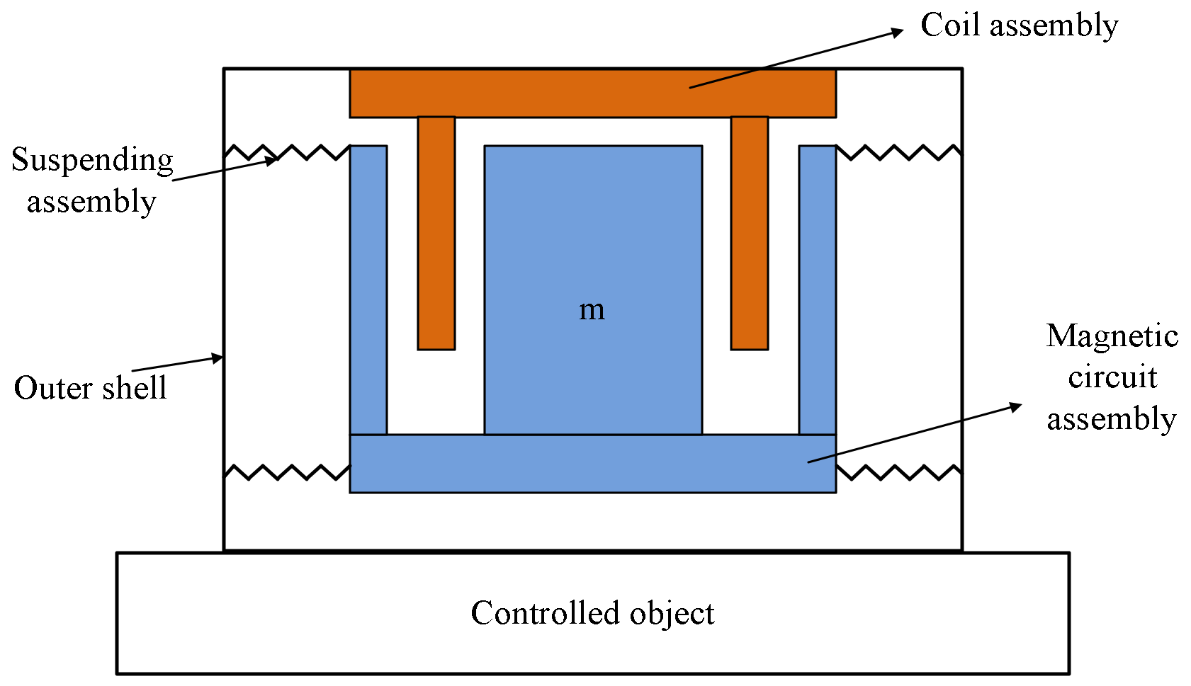
2. The Working Principle of a Maglev Inertial Actuator

The schematic diagram of the working principle of a maglev inertial actuator is shown in Figure 1. The actuator is mainly composed of magnet circuit assembly, coil assembly, suspending assembly and outer shell. The coil is wound on the aluminium alloy frameand fixed with the outer shell, which serves as the stator part of the actuator. The magnetic circuit assembly serves as the acting part, and the spring connects the stator and the acting part as the transmission medium of force. During operation, the coil is placed in a strong and constant magnetic field generated by magnet circuit. After alternating the current pass through the coil, the magnetic circuit assembly is forced to vibrate with a single degree of freedom under the action of Lorentz force. The actuator can use the inertial force generated by the motion of the magnetic circuit assembly to output the active control force.
Assuming that the mass of the controlled object is much greater than the mass of the inertial actuator, then its displacement and velocity can be ignored. The vibration equation of the acting part under the Lorentz force can be written as:
F a + m x ¨ + c x ˙ + k x = 0
where, x is the displacement of the magnetic circuit assembly, m is the mass of the magnetic circuit assembly, k is the stiffness of the spring, c is the damping and Fa is the Lorentz force on the moving magnet.
The output force of the inertial actuator F is:
F = F a + c x ˙ + k x = m x ¨
Making x = x ¨ / ( j w ) 2 and x ˙ = x ¨ / j w , Equation (1) can be converted as:
x ¨ = F a w 2 / m w 2 j c w k
Therefore, the actual output force can be expressed as:
F = m w 2 F a / m w 2 j c w k
According to Equation (4), the output force of the inertia actuator is proportional to Lorentz force. The mass of the magnetic circuit assembly m, the vibration frequency w and the spring stiffness k all have certain effects on the output force of the inertial actuator.
On the basis of Lorentz principle, the Lorentz force Fa can be expressed as:
F a = B I l
where, B is the magnetic induction intensity at the air gap, I is the current in the coil, and L is the effective length of the coil.
According to Kirchhoff’s second voltage law, the voltage balance equation is:
U = e + R I + L · d I / d t = B L x ˙ + R I + L · d I / d t
where, U is the voltage, e is the induced electromotive force ( e = B L x ˙ ), I is the current, R is the resistance of the coil and L is the inductance of the coil.
Taking x ˙ = x ¨ / j w into Equation (3), Equation (6) can be changed to:
U = I ( R + j w L + j w B 2 L 2 / m w 2 + j c w + k )
By substituting Equations (5) and (7) into Equation (4), the relationship between the output force of the maglev inertial actuator and the actual input voltage can be obtained
F = m B L w 2 / m w 2 j c w k · U / R + j w L + j w B 2 L 2 / m w 2 + j c w + k
In addition to the hindrance of resistance, the coil in the alternating electric field will produce inductive reactance, which will increase as the inductance of the coil and the frequency of the alternating current increase. Furthermore, the induction electromotive force is generated when the coil cuts the magnetic induction line in the magnetic field. The above factors will ultimately affect the output force.
Assuming the fundamental frequency and the damping ratio of the maglev inertial actuator is w n and ζ , respectively, then Equation (4) can be changed to:
F / F a = m w 2 / m w 2 j 2 m w n ζ k
Taking λ = w / w n , Equation (9) can be written as:
F / F a = λ 2 / λ 2 j 2 ξ λ 1
When the damping ratio meets 0 < ξ < 2 / 2 , the ratio of the output force to the Lorentz force can reach a maximum if the forced vibration frequency is consistent with the resonant frequency of the acting part. The influence of damping ratio on F/Fa is shown in Figure 2. It can be concluded that the smaller the damping ratio is, the greater the ratio of the output force to the Lorentz force is. As the damping ratio approaches 2 / 2 , the output force is basically equal to the Lorentz force.
Assuming the resonant frequency of the action part of the inertial actuator is 20 Hz and the Lorentz force is 200 N, the output force of the inertial actuator can be obtained as Figure 3 for different damping ratio 0.3, 0.4 and 0.5. It can be seen that the output force can reach a maximum when the forced vibration frequency is the same with the resonant frequency of the acting part. Moreover, the forced vibration frequency plays an important role on the output force. In the low-frequency range, the output force can improve a lot because of the resonance effect, whereas in the high-frequency range, the output force is nearly the same as the Lorentz force. In order to increase the output force at the low-frequency range, the designed natural frequency should be as close to the working frequency as possible.

3. Design of The Proposed Maglev Inertial Actuator

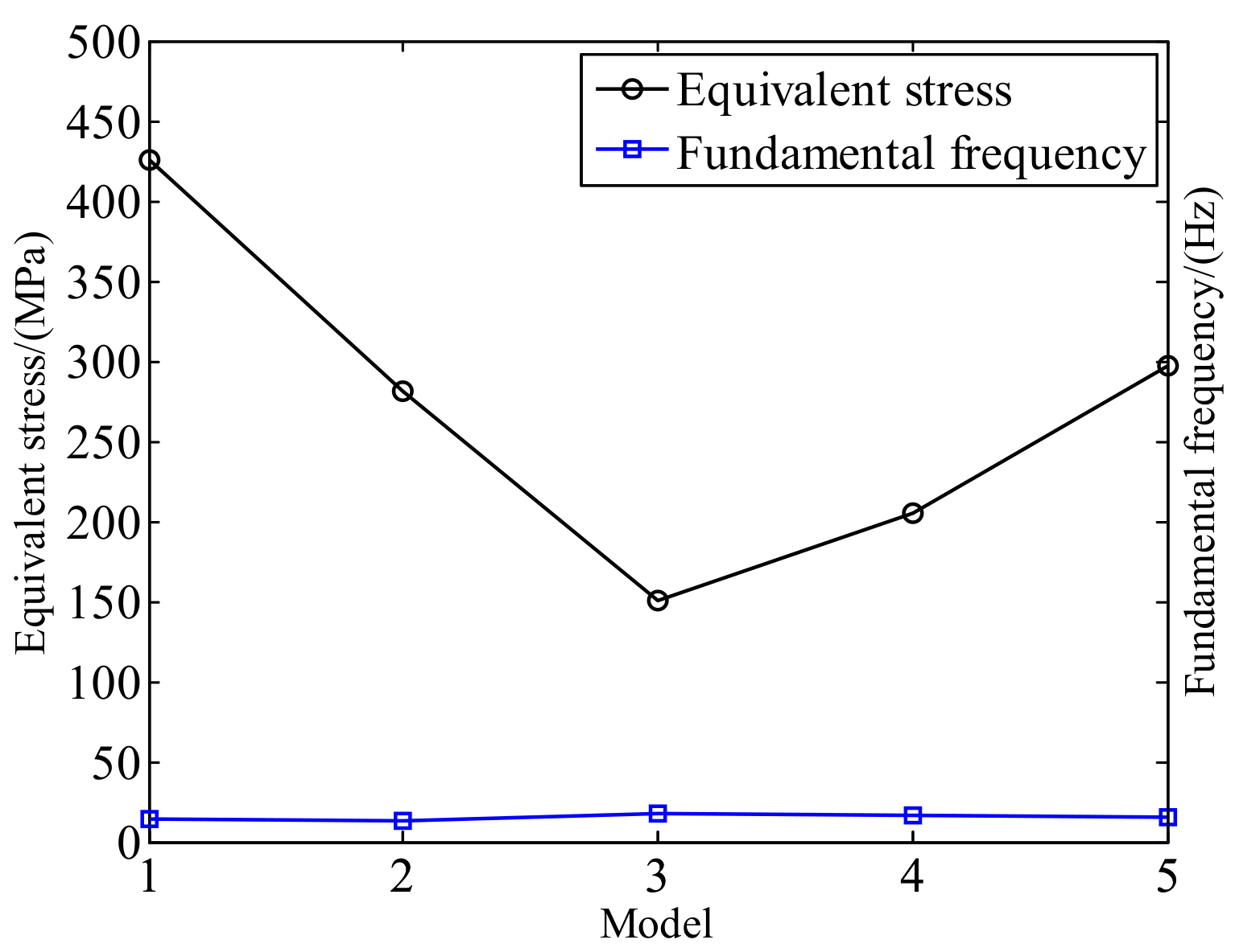
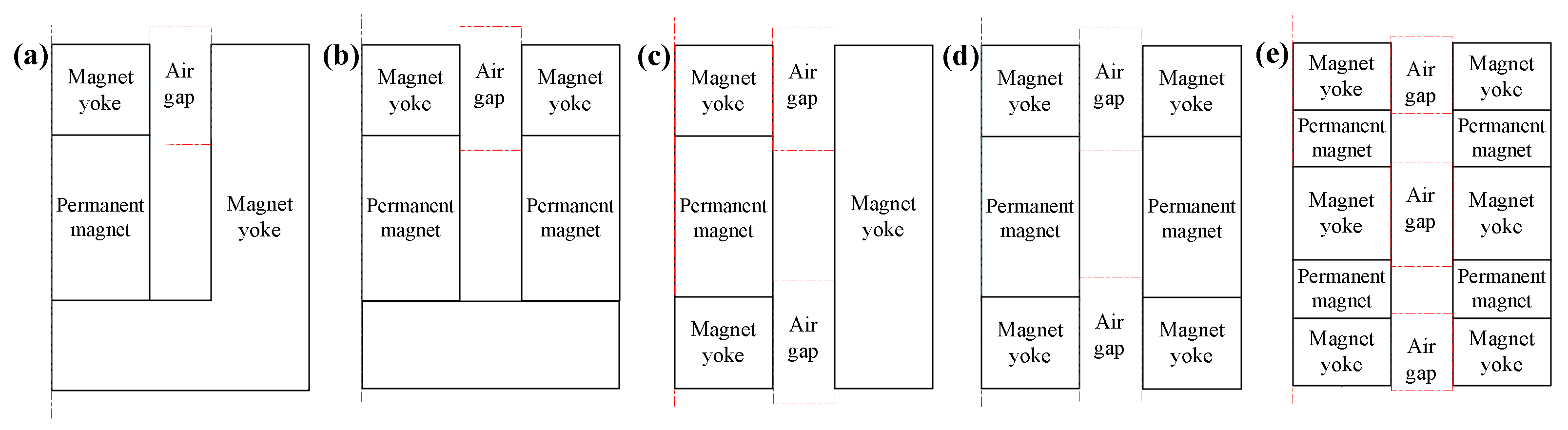
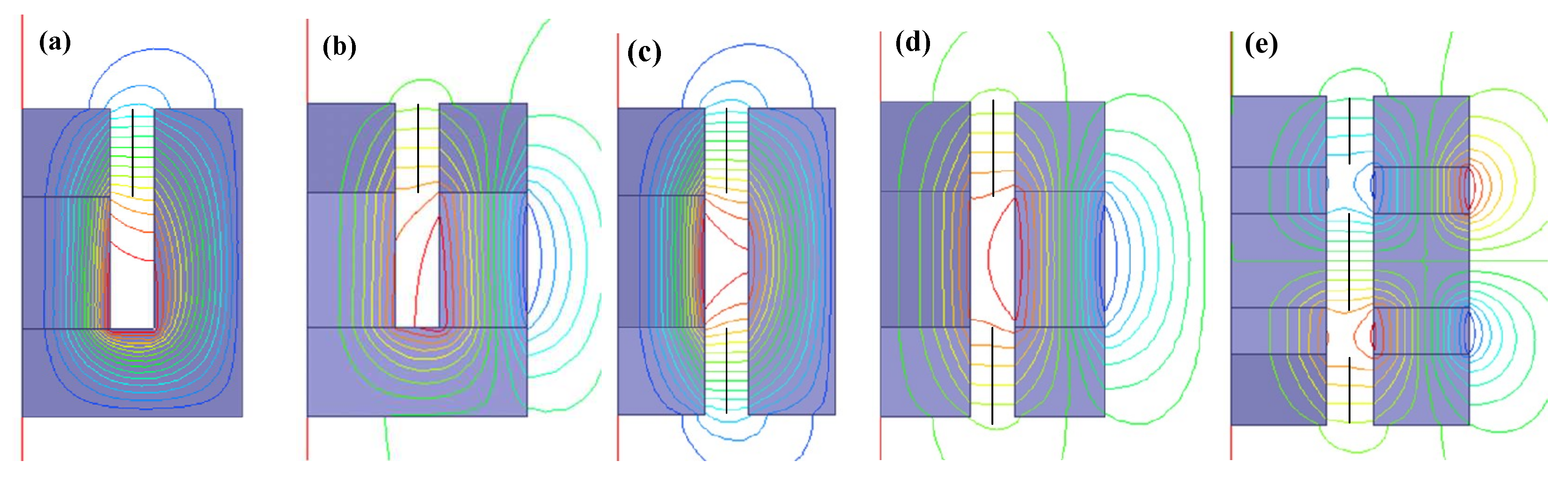
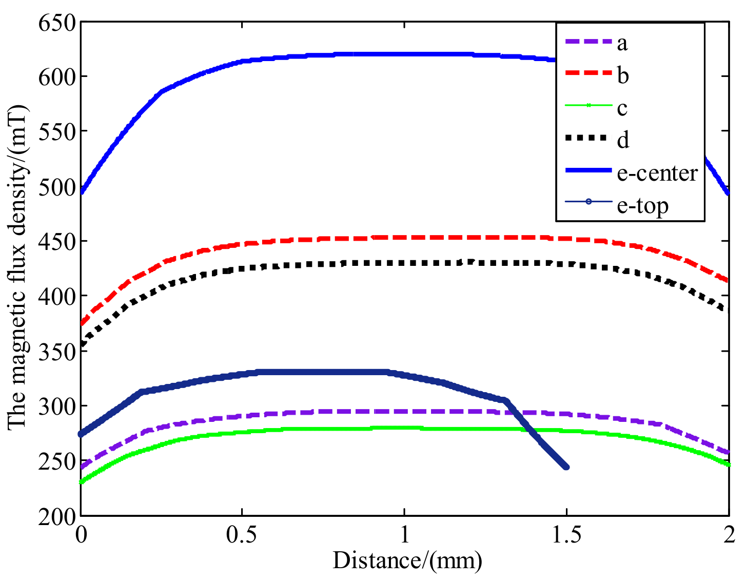
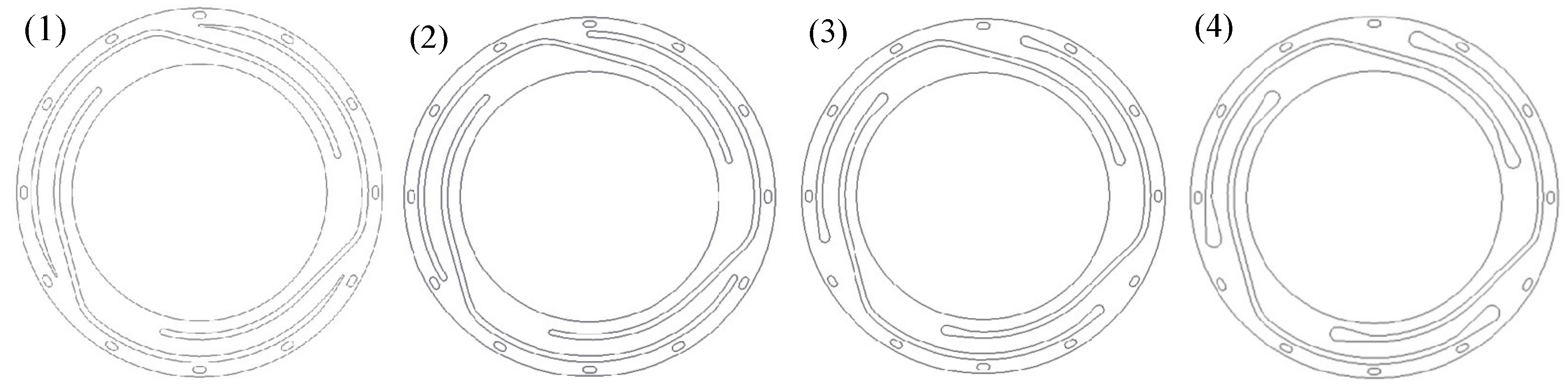
3.1. Design and Scheme Optimization of Magnetic Circuit Assembly

In order to meet the requirements of light weight, small volume and large output force, the structure of the magnetic circuit assembly is quite important. Five kinds of magnetic circuit schemes (a, b, c, d, e) were put forward as shown in Figure 4. NdFeB N35SH and pure iron DT4 were used for simulation respectively. The magnetic flux lines distribution was simulated by 2D Ansys/Maxwell as shown in Figure 5. The magnetic flux density at the center line of the air gap of each scheme is shown in Figure 6. It can be seen that the degree of uniformity of schemes a, b, c and d is better than scheme e. However, the magnetic flux density of scheme e at the center air gap is much greater than other schemes. As the schemes a and b have only one air gap for a coil, schemes c and d have two air gaps, where two coils can be set and double the Lorentz force can be provided. Moreover, scheme e has three air gaps, which can provide greater Lorentz force even though the magnetic flux density at the top air gap and bottom air gap is less than the center. Therefore, schemes d and e may be better than others in terms of the magnitude of the Lorentz force. By considering the application in the frequency range of 100–300 Hz, the eddy current effect of a coil would become a major factor influencing the performance of the actuator. According to part 2, the inductance of the coil needs to be designed as small as possible. In addition, the coil frame with small volume and light mass is superior. Therefore, scheme e may be not a good choice as the coil assembly is complex, which would introduce more eddy current effect. To sum up, scheme d is good with high magnetic flux density and two separate coils can be designed. Therefore, a high mass power ratio can be obtained for the inertial actuator.

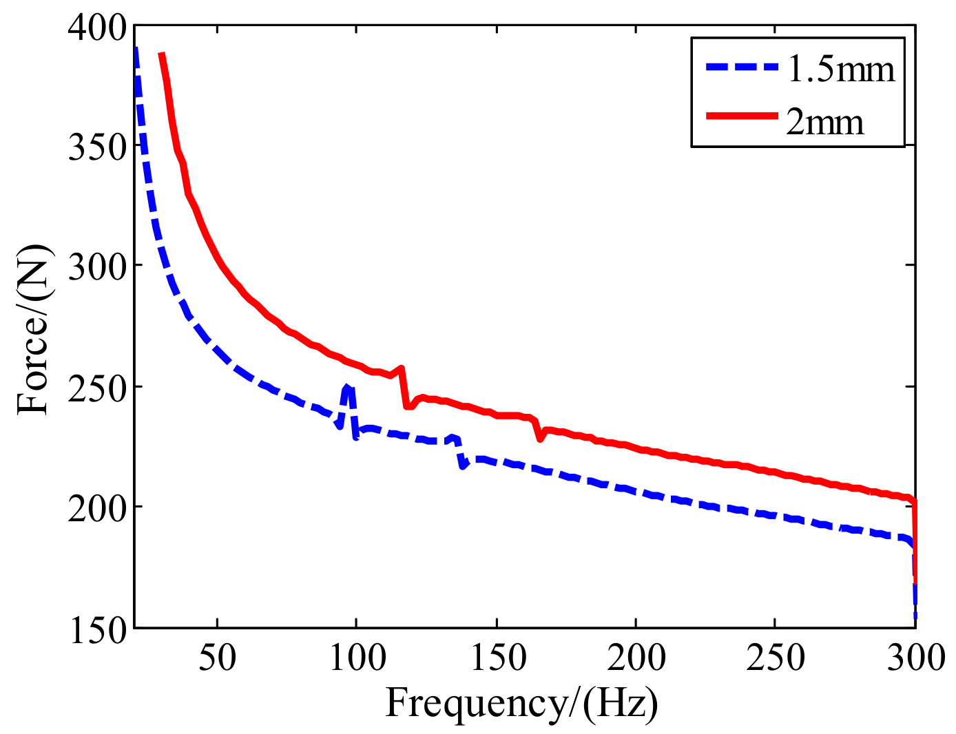
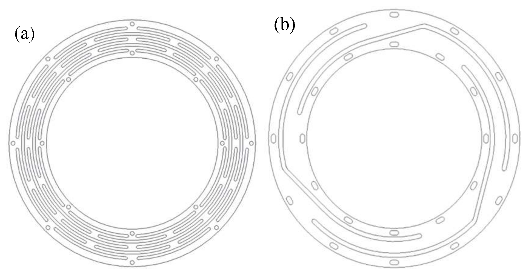
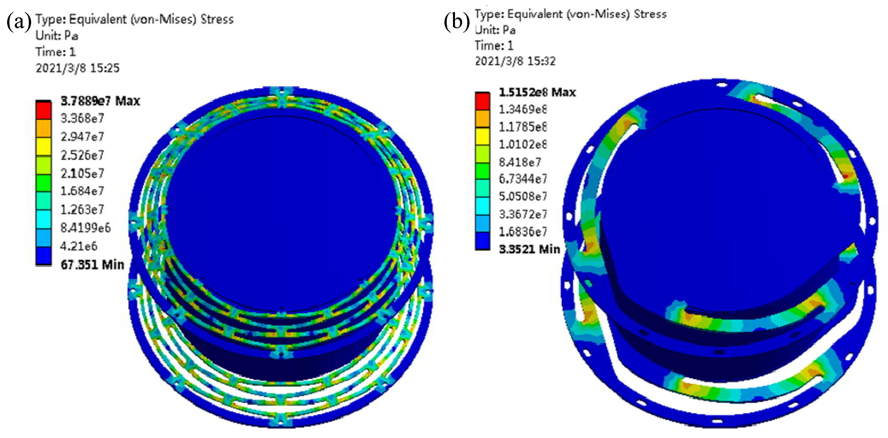
3.2. Design and Scheme Optimization of the Suspending Assembly

The working frequency of the inertial actuator depends on the suspending system. The slit type leaf spring was used to support the magnetic circuit assembly because of its large radial stiffness and small axial stiffness. Two kinds of leaf springs (a, b) with inner diameter 124 mm and outer diameter 178 mm were designed, as shown in Figure 7. The suspension models with two springs and a mass block was constructed and the properties were simulated by a static structural moduleand modal moduleof Ansys/Workbench as shown in Figure 8. The fundamental frequency, maximum stress and deformation of the two models under 200 N are illustrated in Table 1. The fundamental frequency of scheme a is greater than scheme b, which means that the inertial actuator with scheme b has broader frequency range and can work at the frequency as low as 16 Hz. The fundamental frequency can be reduced by increasing the outer diameter of scheme a, but the volume and mass of the inertial would be increased. Therefore, scheme b is better.
The stress concentration of the leaf spring mainly depends on the parameters of the slit, most of which are relevant to each other. Different structures can be obtained by adjusting the gap length, the gap width and the radius of the end of the gap. Four structures of leaf springs were designed as shown in Figure 9. The equivalent stress and fundamental frequency were simulated and compared in Figure 10 with Figure 7b as model 5. It is obvious that model 3 is better than others as the equivalent stress decrease about 50% compared to model 5.

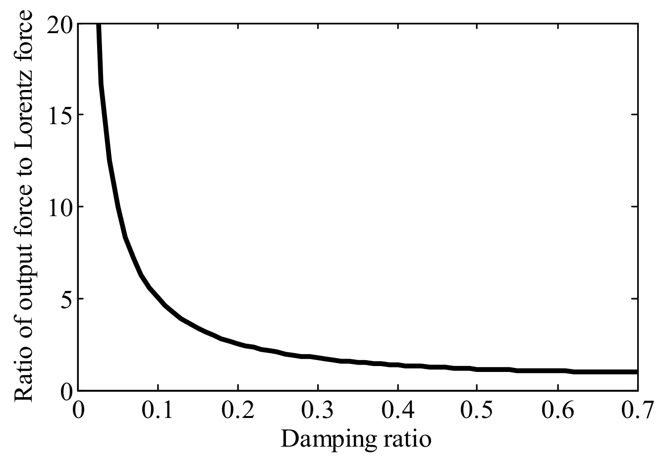
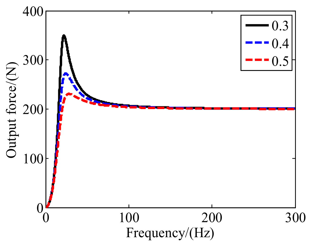
4. Results and Discussion

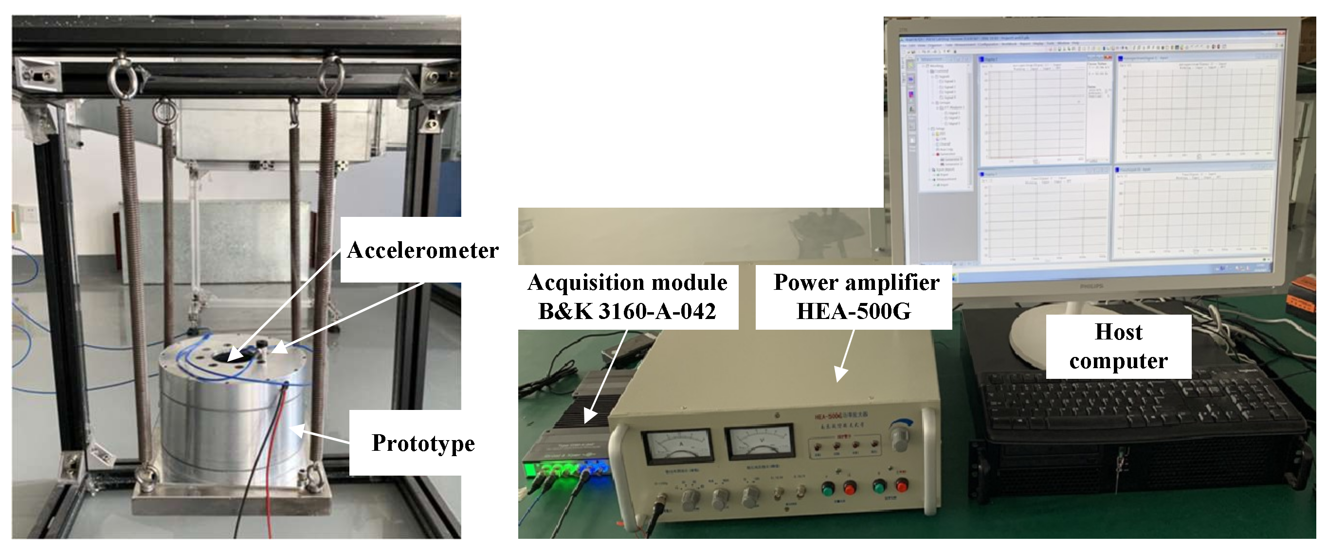
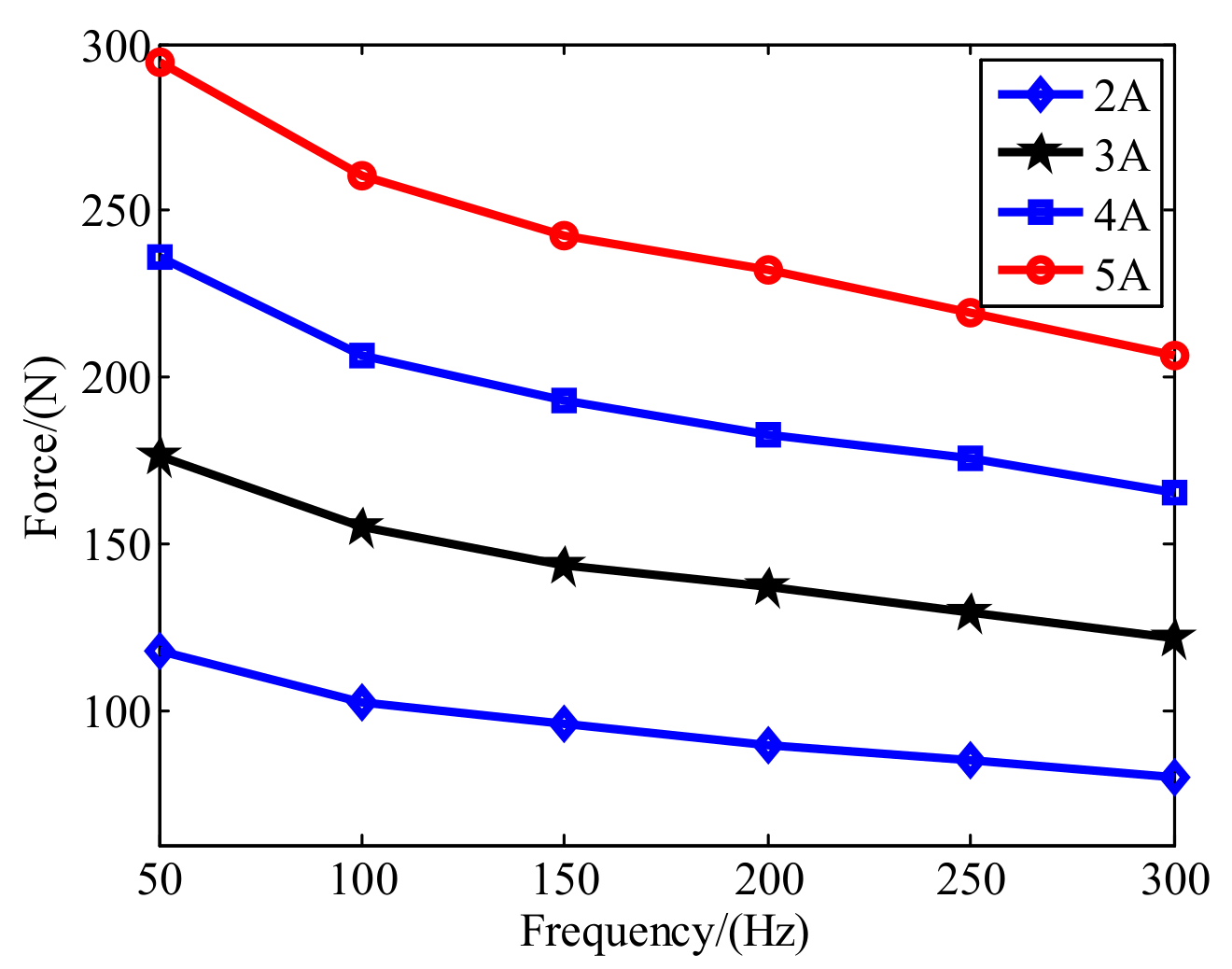
4.1. Results of Prototype Experiments

A magnetic inertial actuator with the optimized magnetic circuit assembly and leaf spring was manufactured. The materials used for the magnetic inertial actuator are listed in Table 2. The inner radius of the two cylindrical permanent magnets are 5 mm and 55 mm, respectively, and the outer radius are 45 mm and 65 mm, respectively. The air gap distance is 10 mm. The number of turns of each coil is 240 and the resistance is 5.1 ohms. The total mass is no more than 8 kg, the maximum outer diameter is 178 mm and the total height is 116 mm. A testing device was set up as shown in Figure 11. The inertial actuator was suspended by four springs together with a mass block weight of 25 kg, with which the fundamental frequency is less than 15 Hz.
The input current of the inertial actuator was adjusted as 2 A, 3 A, 4 A, and 5 A, respectively. The tested acceleration at frequencies 50 Hz, 100 Hz, 150 Hz, 200 Hz, 250 Hz and 300 Hz were recorded and are shown in Figure 12. It can be seen that the relationship between the output force and the input current is nearly linear at different frequencies. With the increase of frequency, the output force decreases slightly due to the effect of impedance, inductive reactance and eddy current loss. The effective output force of the maglev inertial actuator can reach 200 N and more when the current is 5 A.
Two leaf springs with 1.5 mm thickness and 2 mm thickness were manufactured. The fundamental frequencies of the actuators with each leaf spring are 14 Hz and 18 Hz, respectively. The initial input current was set as 5 A and the excitation frequency was increased from 20 Hz to 300 Hz as a sweep function. The output force of the inertial actuator was recorded and shown in Figure 13. The leaf spring with a thickness of 2 mm can produce greater force than the leaf spring with a thickness of 1.5 mm as its fundamental frequency is closer to the working frequency.

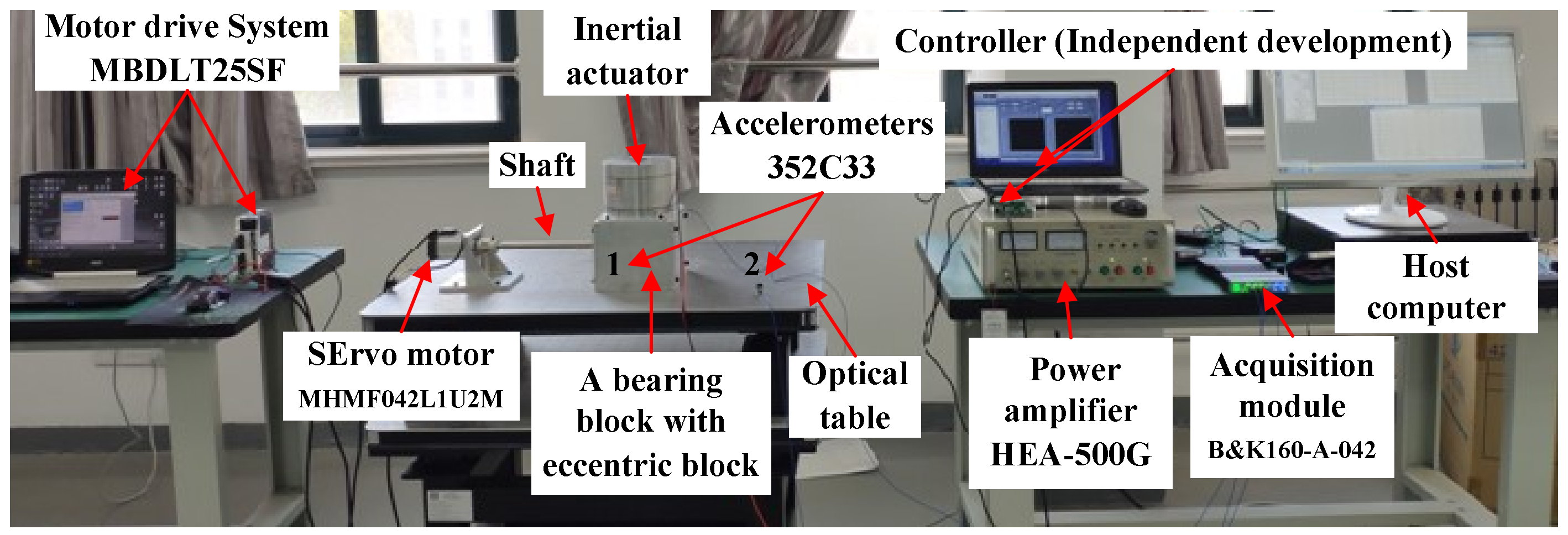
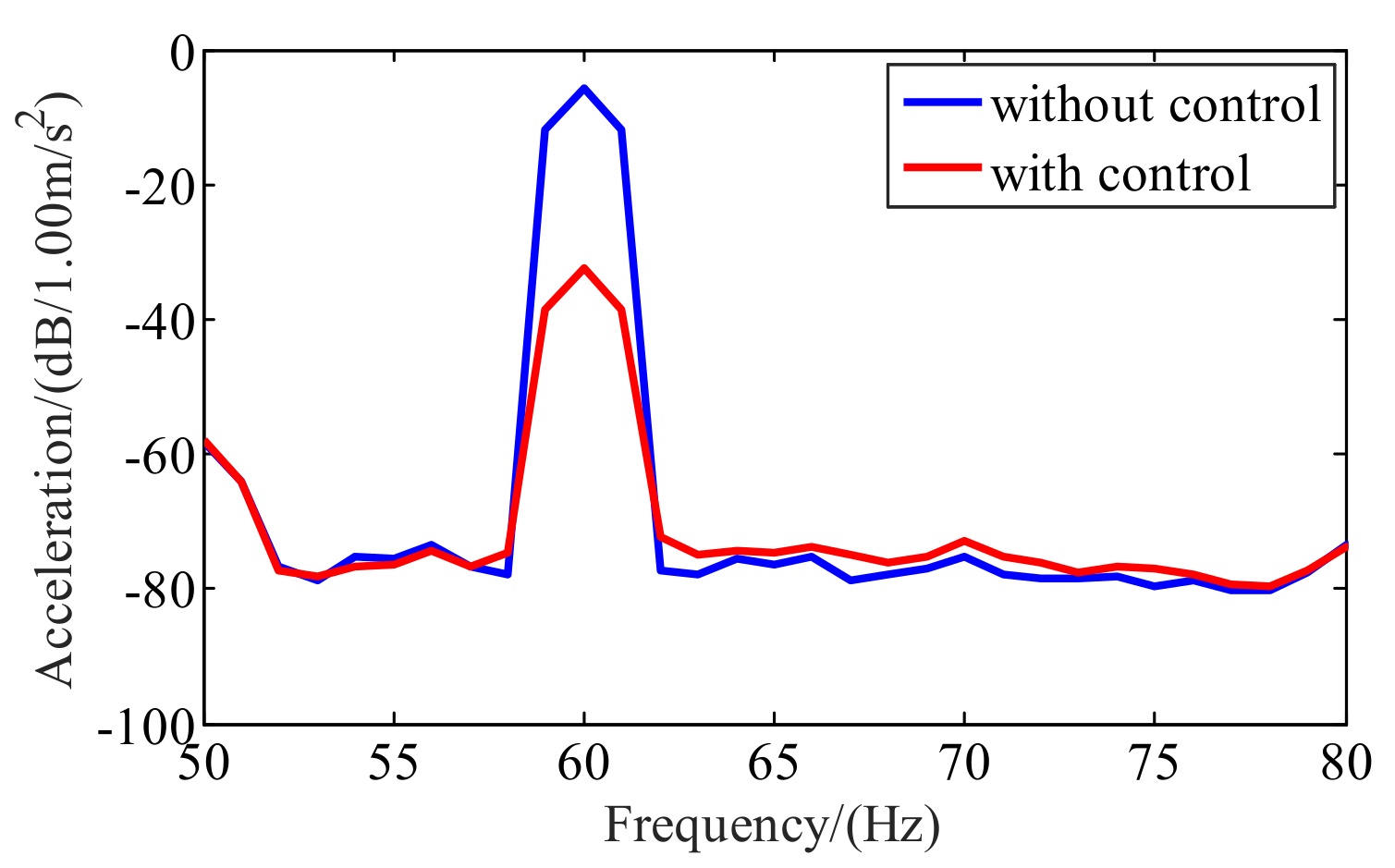
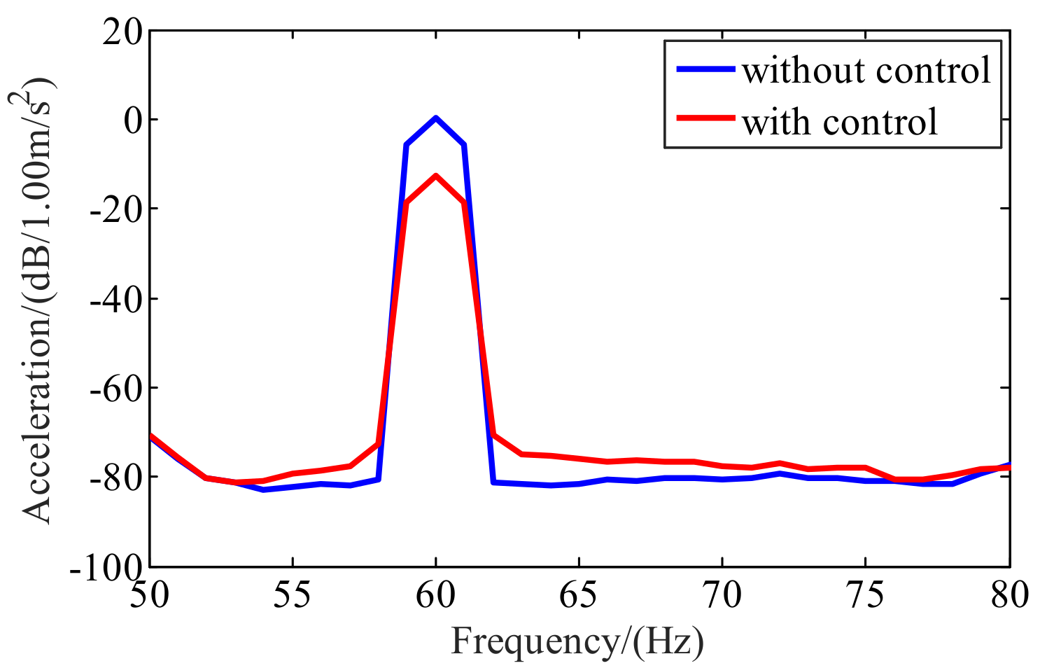
4.2. Results of Active Control of Lateral Vibration of Propulsion Shafting

A test system of propulsion shafting was set up for active control as shown in Figure 14. A servo motor was driven by its driver with the speed range of 0–6000 r/min. One end of the propulsion shaft was connected to the servo motor through an elastic coupling, and the other end was connected to the bearing support through a bearing. Eccentric blocks were installed on the shaft next to the bearing to simulate the lateral vibration of the shaft. Two accelerometers were used. One was installed on the bearing block and the other was installed on the optical table, about 50 cm away from the bearing block.
The classical adaptive feed-forward control was used. A secondary vibration source, caused by the inertial actuator, was introduced. The vibrations are of the same frequency and amplitude, but of opposite phases with the original vibration. Then, the original vibration can be coherently offset to achieve the purpose of vibration suppression. Firstly, the servo motor was shut down. A linear spectrum disturbance signal with 60 Hz was sent out by the controller to the actuator through the power amplifier. Then, the test results of accelerometer 1 can be identified and used to design the controller. Test results with and without control of accelerometers 1 and 2 are shown in Figure 15 and Figure 16, respectively.
It can be seen that the control effect at the position of accelerometer 1 can achieve 27 dB and the control effect at the position of accelerometer 2 can achieve 12 dB. The experimental results prove that the proposed maglev inertial actuator has good control performance.

5. Conclusions

The maglev inertial actuator with high output force, small volume and light mass was presented and its working characteristic was analyzed. A double magnetic field scheme was chosen to acquire a high mass power ratio as well as greater Lorentz force. Furthermore, the suspending assembly schemes with slit-type leaf springs were designed and compared to obtain one with broader working frequency range and small stress. A prototype of the proposed maglev inertial actuator with mass less than 8 kg was developed. The effective output force was tested by more than 200 N within the frequency band of 20–300 Hz. A propulsion shafting system for lateral vibration control was constructed to test the control performance of the proposed inertial actuator. At 60 Hz, the control effect can reach 27 dB at the bearing block of the shaft, and the control effect can reach 12 dB at the position about 50 cm away from the bearing block. The experiments prove that the proposed maglev inertial actuator is effective to achieve lateral vibration control of shafting.

Author Contributions

Conceptualization, Q.W. and Z.L.; methodology, Q.W.; software, Q.W.; validation, Q.W., F.A. and B.L.; formal analysis, Q.W.; investigation, Z.L.; resources, Q.W.; data curation, Q.W.; writing—original draft preparation, Q.W.; writing—review and editing, F.A. and B.L.; visualization, F.A.; supervision, B.L.; project administration, Q.W.; funding acquisition, Q.W. All authors have read and agreed to the published version of the manuscript.

Funding

This research was funded by National Natural Science Foundation of China, grant number 51905288, Applied Basic Research Program of Science and Technology of Qingdao, grant number 19-6-2-61-cg and Open Project of Key Laboratory of Industrial Fluid Energy Conservation and Pollution Control, Ministry of Education.

Data Availability Statement

The data presented in this study are available on request from the corresponding author.

Conflicts of Interest

The authors declare no conflict of interest.

References

  1. Lin, C.G.; Zou, M.S.; Sima, C. Friction-induced vibration and noise of marine stern tube bearings considering perturbations of the stochastic rough surface. Tribol. Int. 2019, 131, 661–671. [Google Scholar] [CrossRef]
  2. Lucke, K.; Martin, S.B.; Racca, R. Evaluating the predictive strength of underwater noise exposure criteria for marine mammals. J. Acoust. Soc. Am. 2020, 147, 3985–3991. [Google Scholar] [CrossRef] [PubMed]
  3. Xie, X.; Ren, M.; Zhu, Y.; Zhang, Z. Simulation and experiment on lateral vibration transmission control of a shafting system with active stern support. Int. J. Mech. Sci. 2019, 170, 105363. [Google Scholar] [CrossRef]
  4. Fereidoun, A.; Hassan, R.; Majid, A.A. Adaptive control of rotationally non-linear asymmetric structures under seismic loads. Struct. Eng. Mech. 2018, 65, 721–730. [Google Scholar] [CrossRef]
  5. Serdar, U.; Gebrail, B.; Sinan, M.N. Active structural control via metaheuristic algorithms considering soil-structure interaction. Struct. Eng. Mech. 2020, 75, 175–191. [Google Scholar] [CrossRef]
  6. Lu, Y.-F.; Yue, H.-H.; Deng, Z.-Q.; Tzou, H.-S. Adaptive shape control for thermal deformation of membrane mirror with in-plane PVDF actuators. Chin. J. Mech. Eng. 2018, 31, 9. [Google Scholar] [CrossRef] [Green Version]
  7. Su, Z.Q.; Zhou, M.; Han, F.F.; Zhu, Y.W.; Song, D.L.; Guo, T.T. Attitude control of underwater glider combined reinforcement learning with active disturbance rejection control. J. Mar. Sci. Tech. 2019, 24, 686–704. [Google Scholar] [CrossRef]
  8. Wang, R.; Li, X.; Liu, Y.; Ahemd, Q.; Yang, Y.; Feng, C.; Ma, X. Variable sampling rate based active disturbance control for a marine diesel engine. Electronics 2019, 8, 370. [Google Scholar] [CrossRef] [Green Version]
  9. Kitamura, E.; Nabae, H.; Endo, G.; Suzumori, K. Self-excitation pneumatic soft actuator inspired by vocal cords. Sensor Actuator A Phys. 2021, 331, 112816. [Google Scholar] [CrossRef]
  10. Nahian, S.A.; Dinh, T.Q.; Dao, H.V.; Ahn, K.K. An unknown input observer-EFIR combined estimator for electro-hydraulic actuator in sensor fault tolerant control application. IEEE/ASME Trans. Mechatron. 2020, 5, 2208–2219. [Google Scholar] [CrossRef]
  11. Kim, M.; Kim, H.; Gweon, D. Design and optimization of voice coil actuator for six degree of freedom active vibration isolation system using Halbach magnet array. Rev. Sci. Instrum. 2012, 83, 105–117. [Google Scholar] [CrossRef] [PubMed]
  12. Zhang, T.; Yang, B.T.; Li, H.; Meng, G. Dynamic modeling and adaptive vibration control study for giant magnetostrictive actuators. Sensor Actuator A Phys. 2013, 190, 96–105. [Google Scholar] [CrossRef]
  13. Csencsics, E.; Thier, M.; Hainisch, R.; Schitter, G. System and control design of a voice coil actuated mechanically decoupling two-body vibration isolation system. IEEE/ASME Trans. Mechatron. 2017, 23, 321–330. [Google Scholar] [CrossRef]
  14. Hong, J.; Wang, S.; Sun, Y.; Cao, H. A method of modal parameter estimation of the motor based on electromagnetic vibration exciter. IEEE Trans. Ind. Appl. 2020, 56, 2636–2643. [Google Scholar] [CrossRef]
  15. Wang, T.; Liu, Y.; Xu, Q.-N.; Han, D. Novel structure for waveform control of twin rotary flowrate valve controlled vibration exciter. IEEE/ASME Trans. Mechatron. 2021, 26, 1183–1188. [Google Scholar] [CrossRef]
  16. Grodsinsky, C.M.; Whorton, M.S. Survey of active vibration isolation systems for microgravity applications. J. Spacecr. Rockets 2000, 37, 586–596. [Google Scholar] [CrossRef] [Green Version]
  17. Kim, M.H.; Kim, H.Y.; Kim, H.C.; Ahn, D.; Gweon, D.G. Design and control of a 6-DOF active vibration isolation system using a Halbach magnet array. IEEE/ASME Trans. Mechatron. 2016, 21, 2185–2196. [Google Scholar] [CrossRef]
  18. Kato, H.; Mashino, M.; Ishida, M.; Hasegawa, S.; Oshinoya, Y. Active seat suspension for ultra-compact electric vehicle: Fundamental consideration on ride comfort evaluation using myoelectric potential. J. Jpn. Soc. Appl. Electromagn. Mech. 2015, 23, 74–79. [Google Scholar] [CrossRef] [Green Version]
  19. Foo, E.; Goodall, R. Active suspension control of flexible-bodied railway vehicles using electro-hydraulic and electro-magnetic actuators. Control Eng. Pract. 2000, 8, 507–518. [Google Scholar] [CrossRef]
  20. Caresta, M. Active control of sound radiated by a submarine in bending vibration. J. Sound Vib. 2011, 330, 615–624. [Google Scholar] [CrossRef]
  21. Janzen, P.C.; Keas, P.J. Implementation of an active vibration damping system for the SOFIA telescope assembly. In Proceedings of SPIE Ground-Based and Airborne Telescopes V; SPIE: Bellingham, WA, USA, 2014; Volume 91452, p. 91452N. [Google Scholar] [CrossRef]
Figure 1. Schematic diagram of working principle of the maglevinertial actuator.
Actuators 10 00315 g001
Figure 2. The influence of damping ratio on F/Fa.
Actuators 10 00315 g002
Figure 3. The influence of frequency on the output force of actuator.
Actuators 10 00315 g003
Figure 4. Different magnetic circuit schemes for the inertial actuator.
Actuators 10 00315 g004
Figure 5. Results of magnetic flux distribution for different magnetic circuit schemes.
Actuators 10 00315 g005
Figure 6. The magnetic flux density at the gap.
Actuators 10 00315 g006
Figure 7. Two kinds of leaf spring for the suspending system.
Actuators 10 00315 g007
Figure 8. Simulation results of the equivalent stress of the springs.
Actuators 10 00315 g008
Figure 9. Four kinds of structure with different slit parameters.
Actuators 10 00315 g009
Figure 10. The total deformation of the proposed leaf spring.
Actuators 10 00315 g010
Figure 11. The maglev inertial actuator and its testing device.
Actuators 10 00315 g011
Figure 12. Results of single frequency excitation.
Actuators 10 00315 g012
Figure 13. Results of sweep frequency excitation.
Actuators 10 00315 g013
Figure 14. Test system of propulsion shafting.
Actuators 10 00315 g014
Figure 15. Test results of accelerometer 1.
Actuators 10 00315 g015
Figure 16. Test results of accelerometer 2.
Actuators 10 00315 g016
Table 1. Performance comparison of two kinds of spring.
SchemeFundamental FrequencyEquivalent Stress
a58.022 Hz37.9 MPa
b15.409 Hz297 MPa
Table 2. Materials used for the magnetic inertial actuator.
MaterialsElectrical Conductivity (S/m)Magnetic Conductivity (H/m)Thermal Conductivity (W/mK)Density
(g/cm3)
Specific Heat J/(kg·°C)
Aluminium alloy frame 60613.5 × 1074π × 10−71502.70.88 × 103
Magnet yokeDT49.93 × 1064000 × 4π × 10−746.57.80.46 × 103
Leaf spring 65Mn9.93 × 106129 × 4π × 10−746.57.80.46 × 103
Permanent magnet N35SH7 × 1051.05 × 4π × 10−789.557.80.50 × 103
Publisher’s Note: MDPI stays neutral with regard to jurisdictional claims in published maps and institutional affiliations.

