
SMARCOS: Off-the-Shelf Smart Compliant Actuators for Human–Robot Applications

 ,
,  , , ,
, , ,  , , and
Abstract
:1. Introduction
2. Materials and Methods
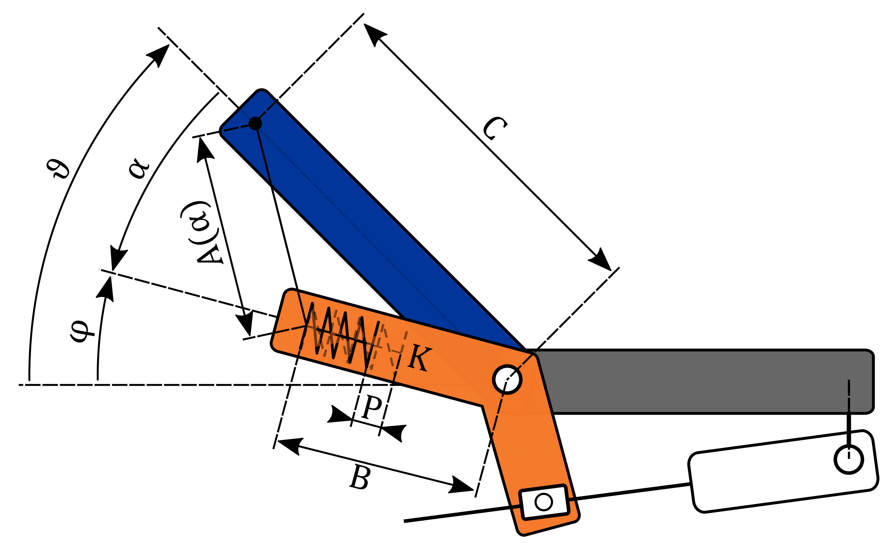
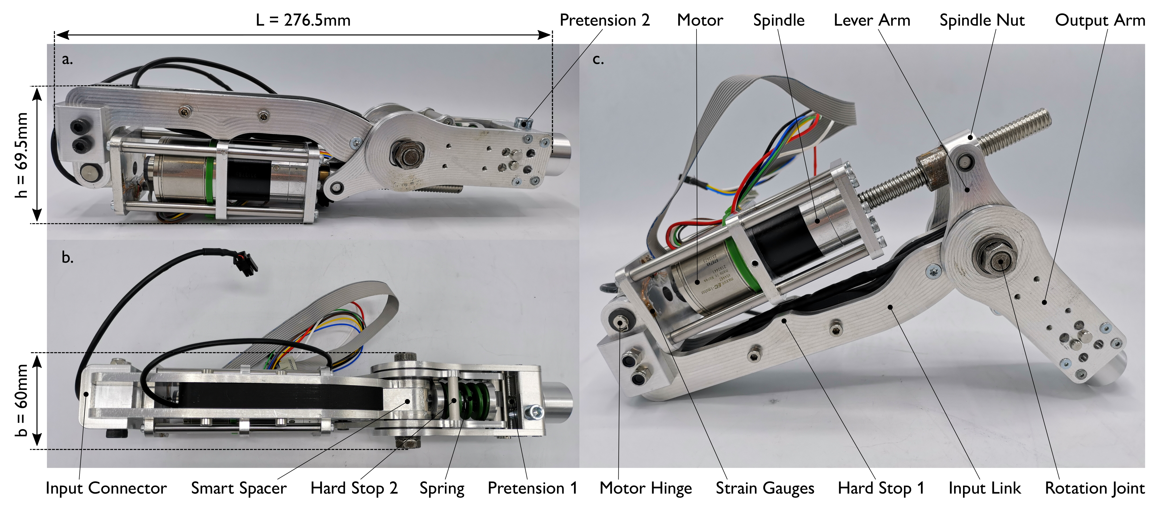
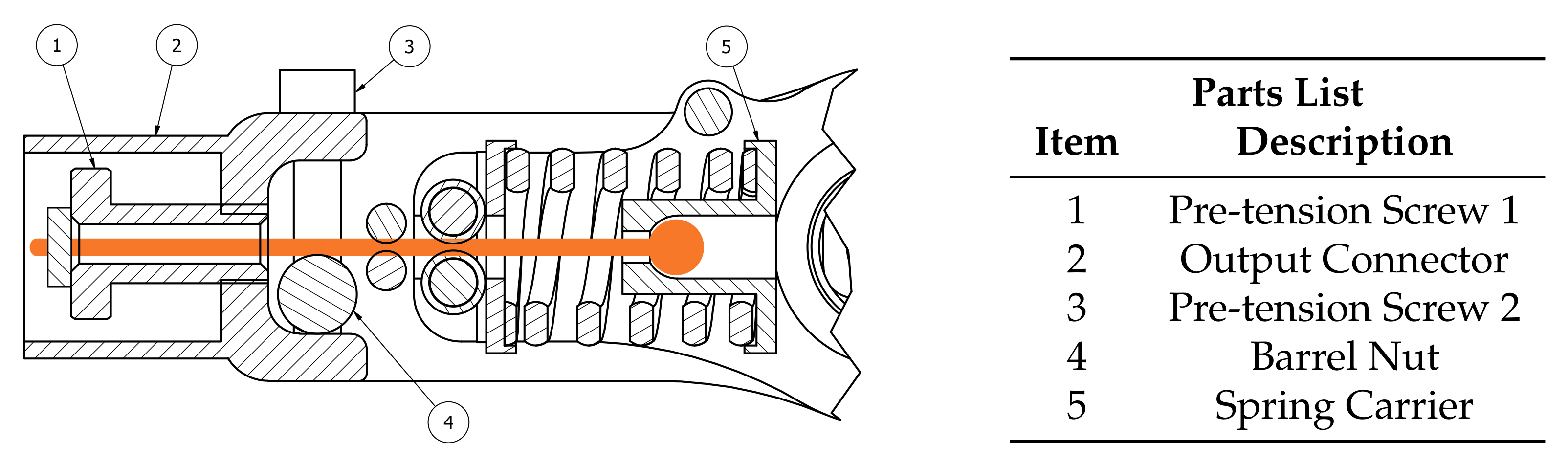
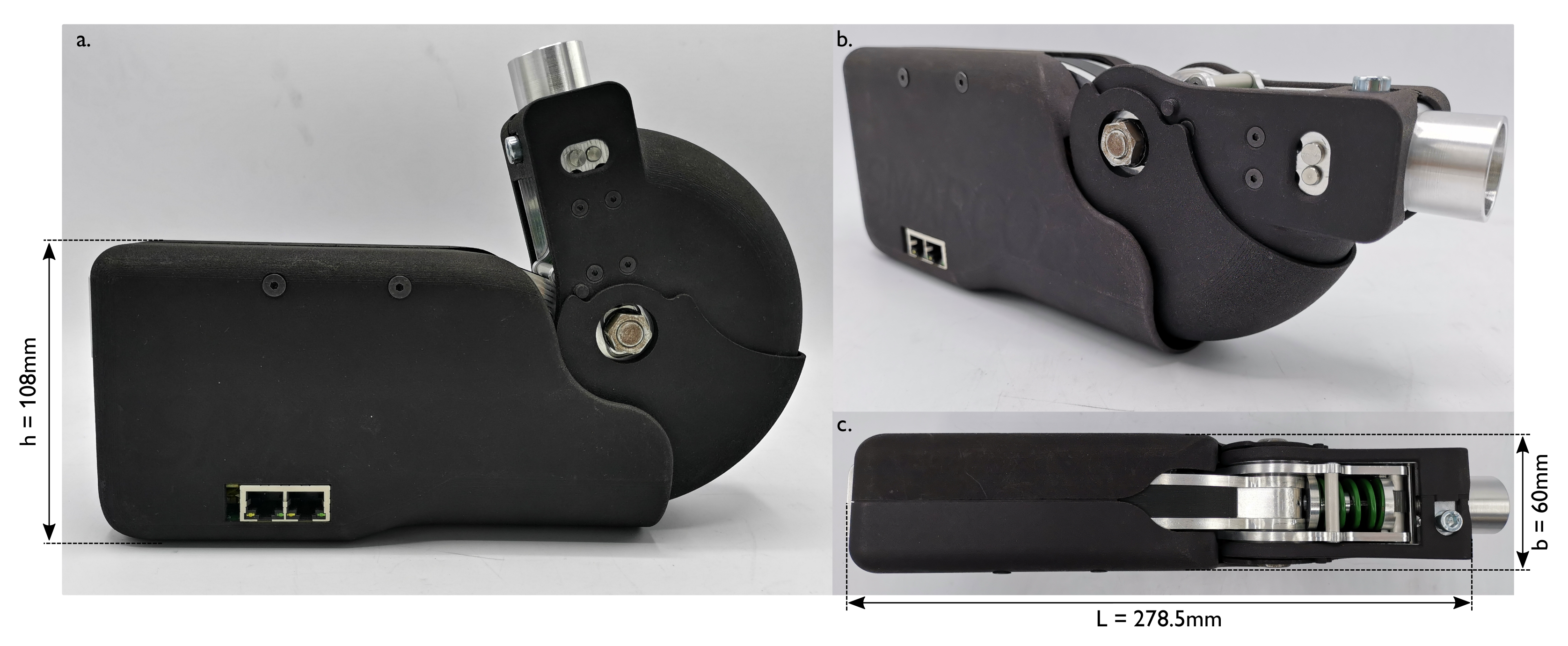
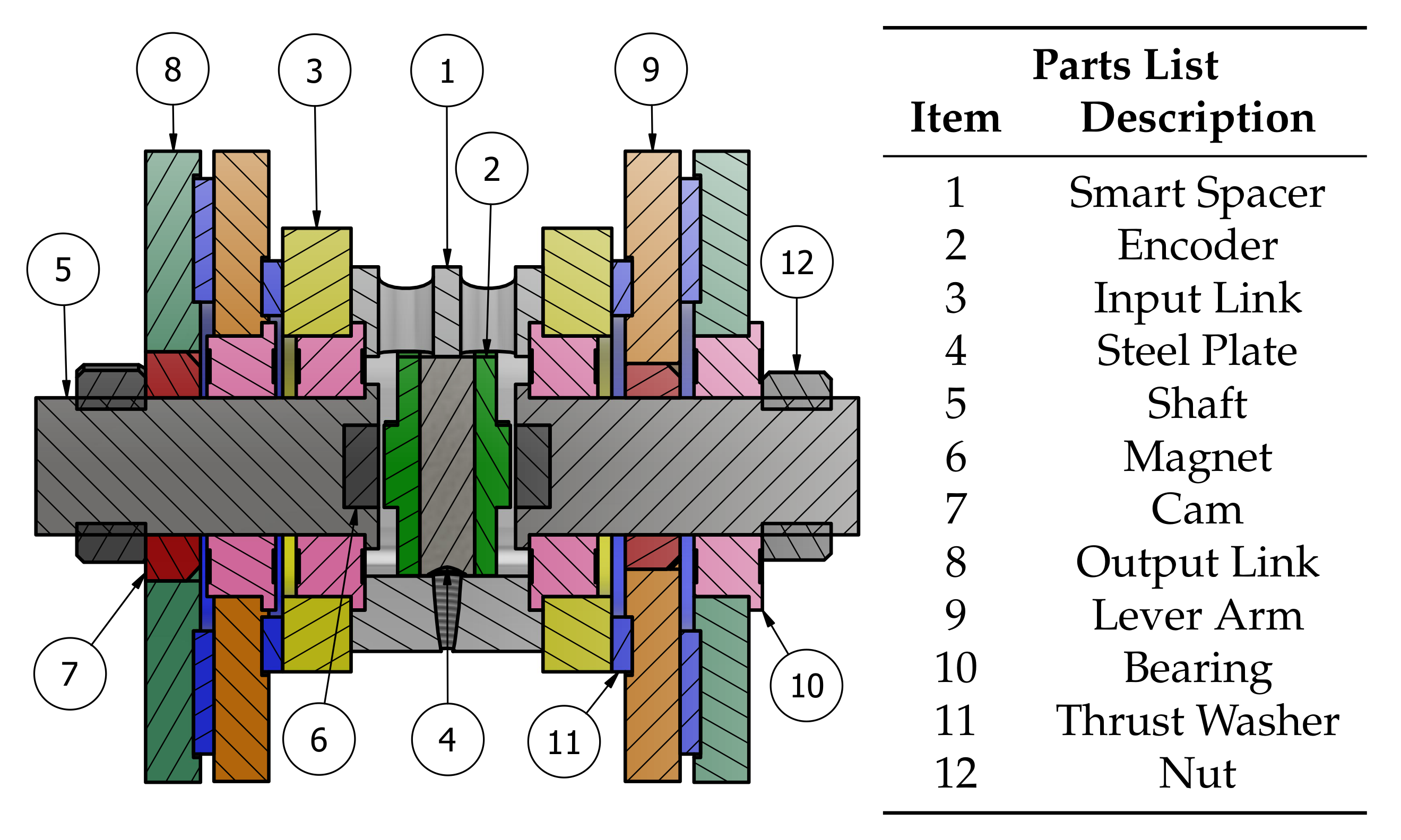
2.1. Mechanical Design
- is the length between the connecting points of the lever arm and output arm;
- B is the length of the lever arm (fixed);
- C is the length of the output arm (fixed);
- K is the spring stiffness (fixed);
- P is the spring pre-compression.
2.2. Sensors
2.2.1. Encoders
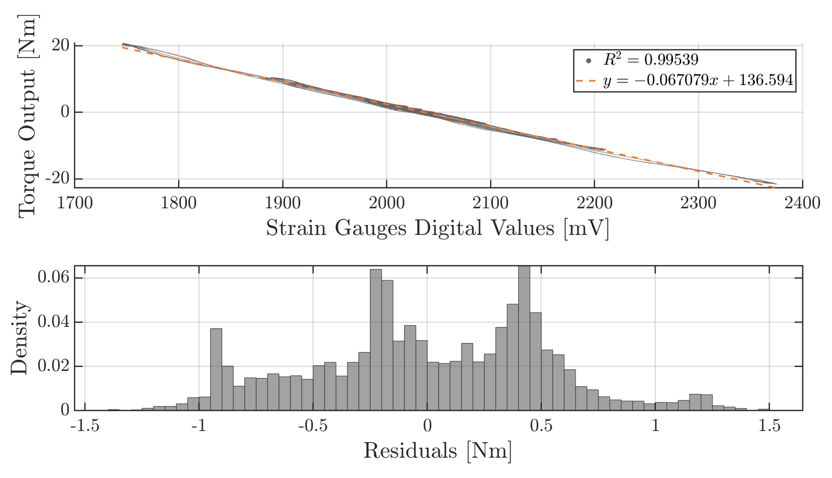
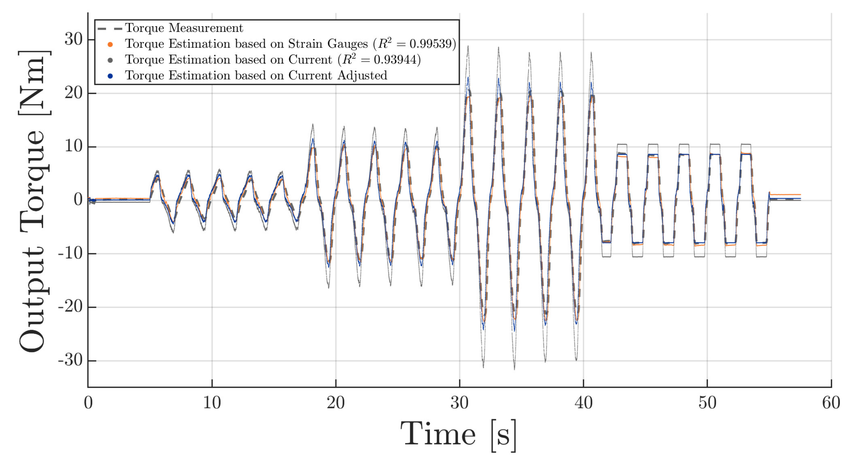
2.2.2. Strain Gauges
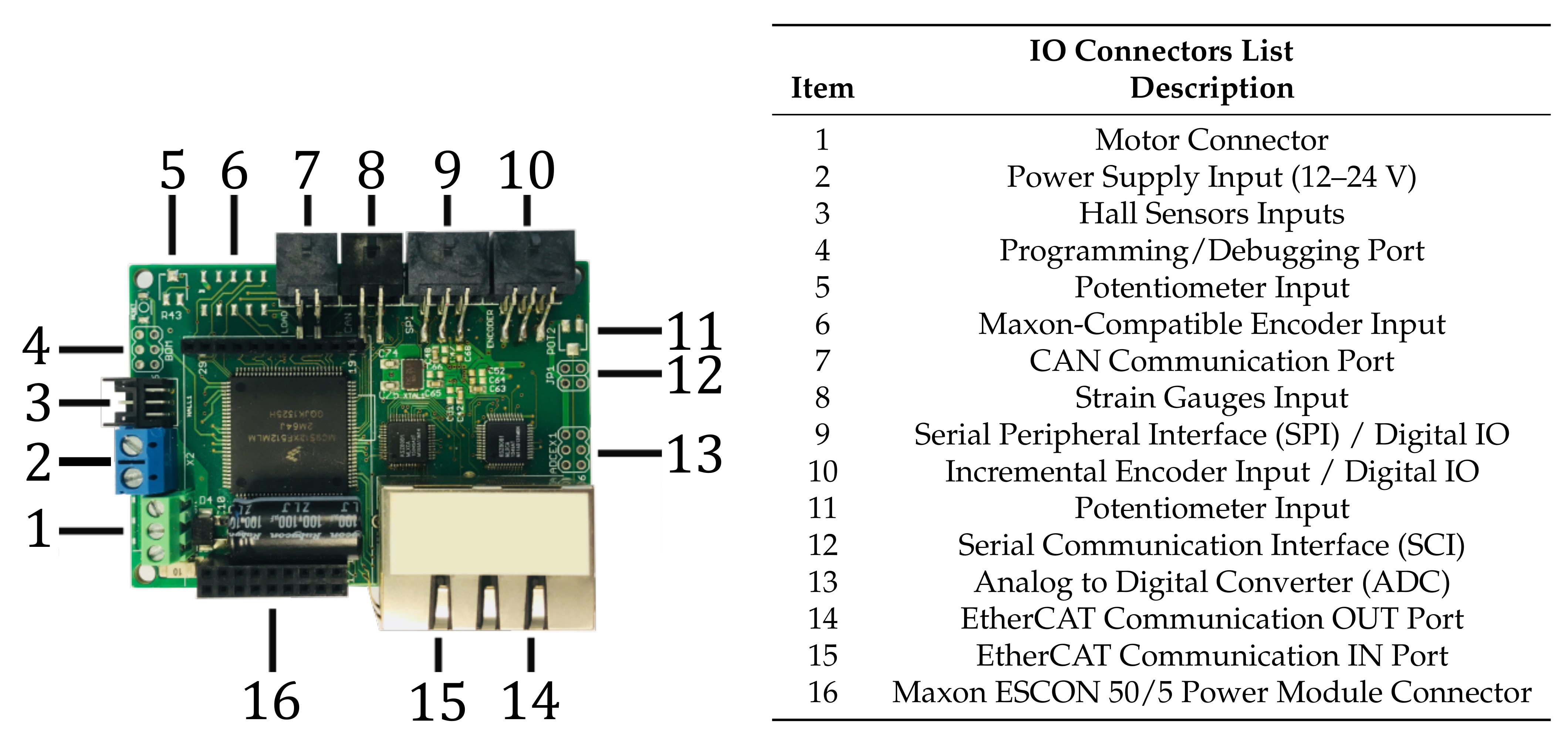
2.3. Electronics
- sensors interfacing, data acquisition and processing;
- low-level control of the motor;
- data communication with the master computer.
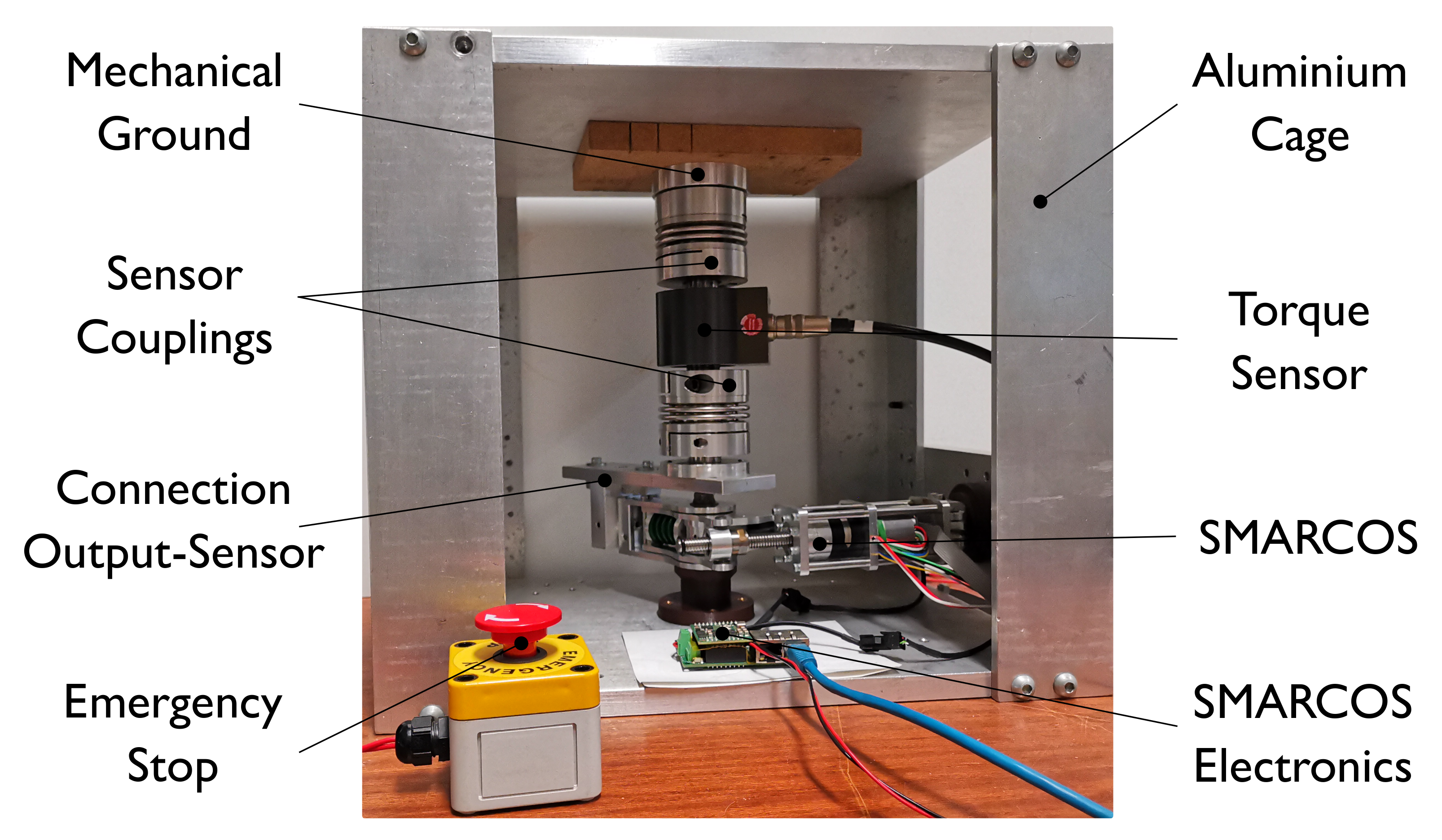
2.4. Test Bench for Characterisation
- quasi-static torque-deflection cycles (for several spring precompressions);
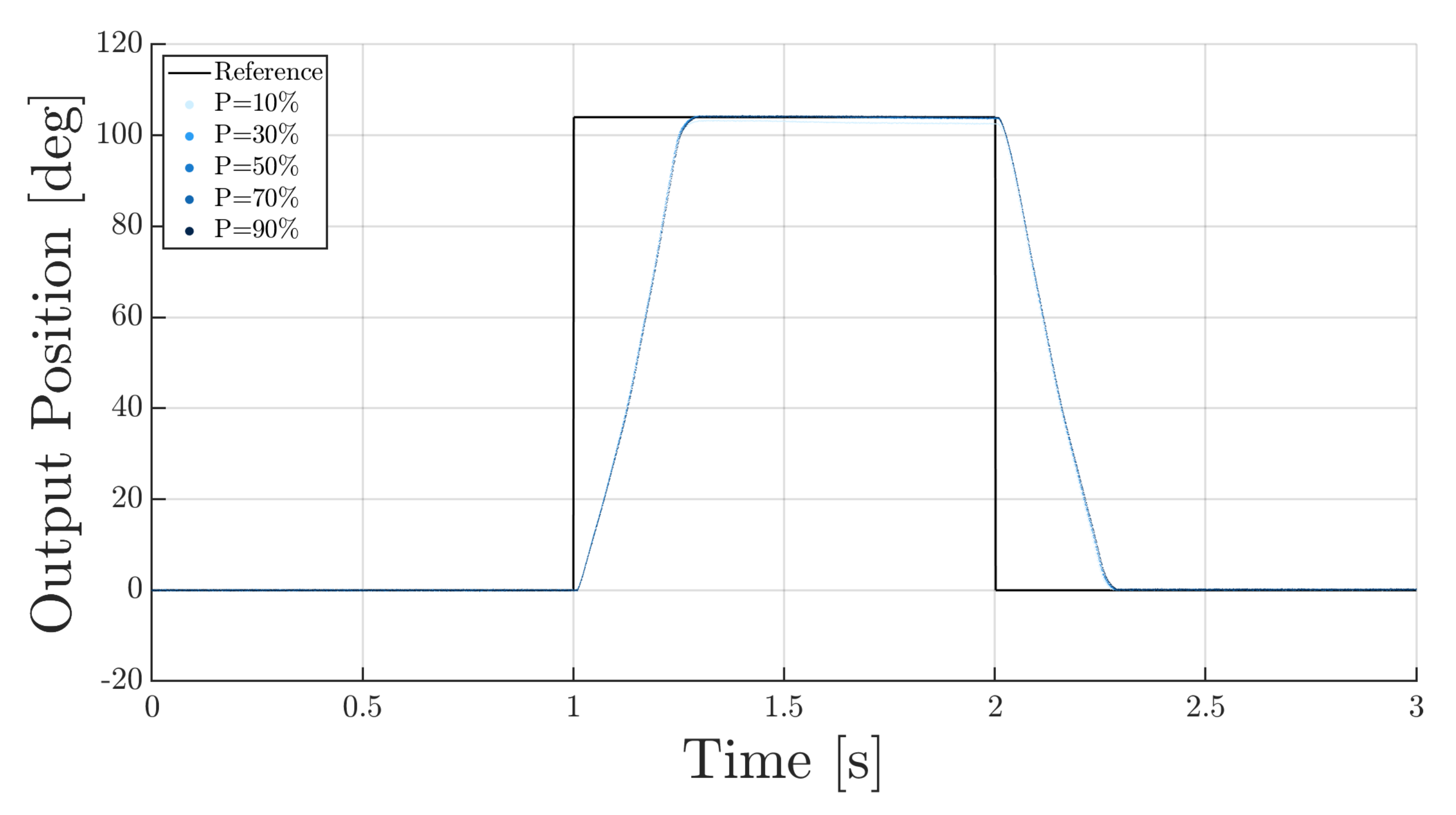
- position step response (for several spring precompressions).
- an aluminium cage, with mechanical grounding part;
- an ETH Messtechnik DRBK-200 Nm (0.0122 Nm/c) torque sensor;
- a Maxon EPOS4 70/10 Motor Drive;
- a Beckhoff EK1400 EtherCAT G Coupler;
- a Beckhoff EL3101 EtherCAT Terminal, 1-channel analog input;
- a TDK-Lambda 0–60 V, 0–10 A Power Supply.
3. Results
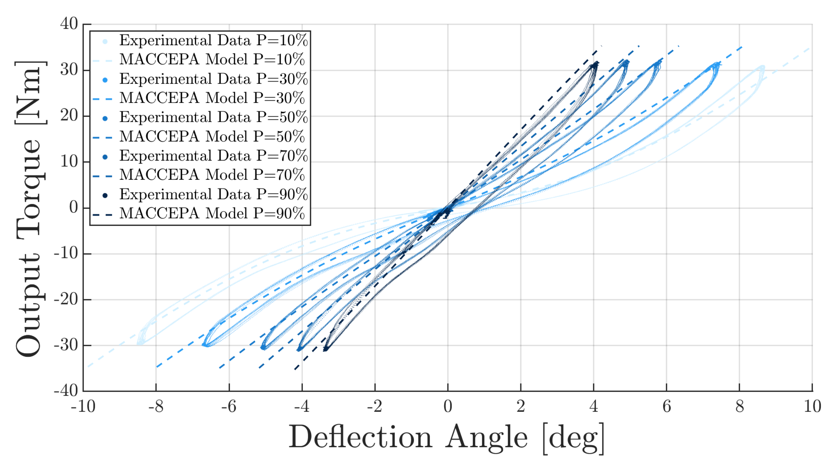
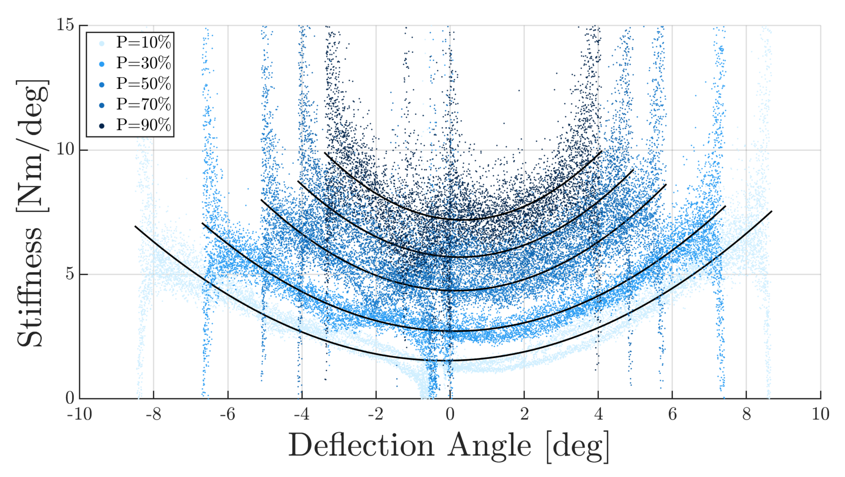
3.1. Quasi-Static Characterisation
3.2. Step Response
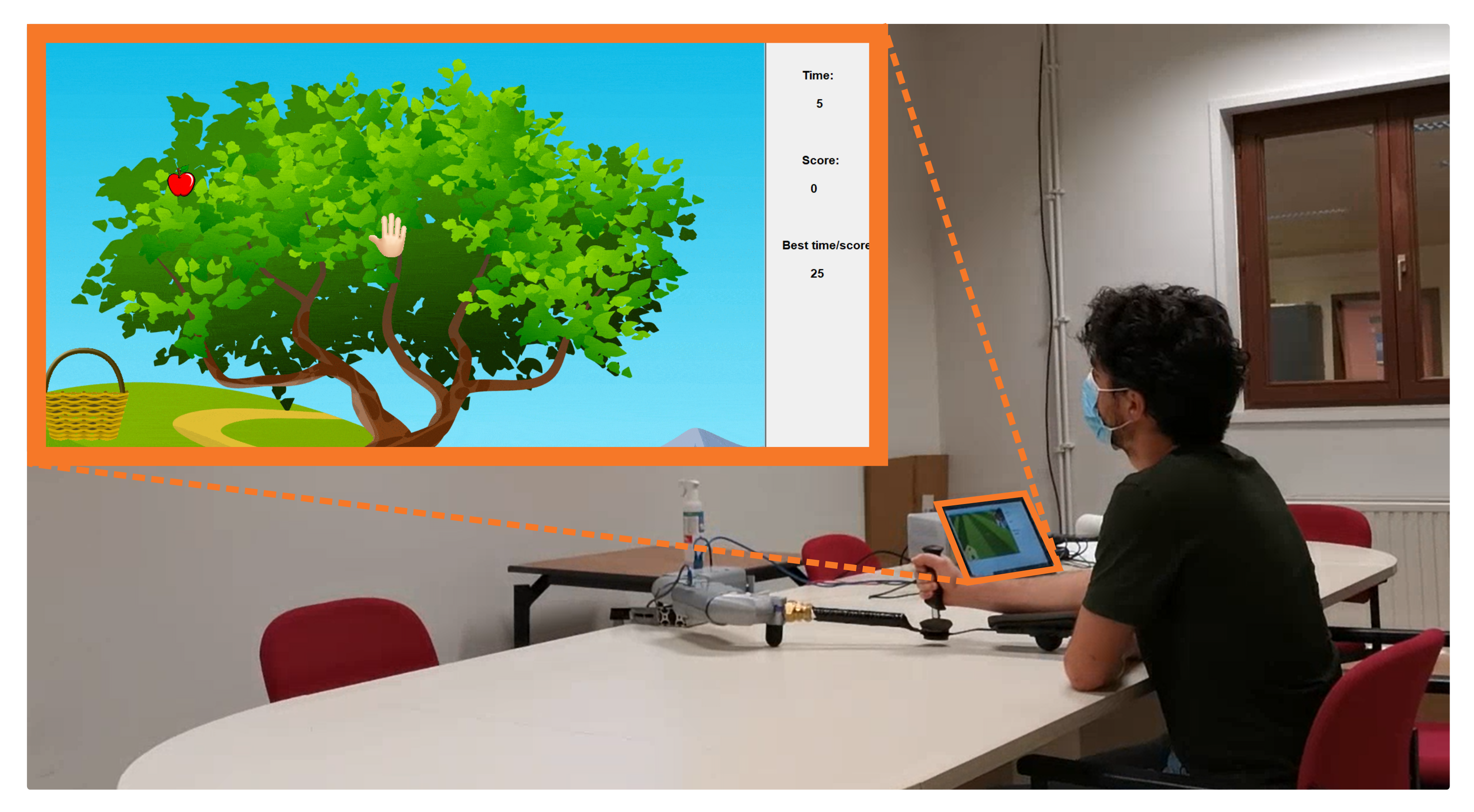
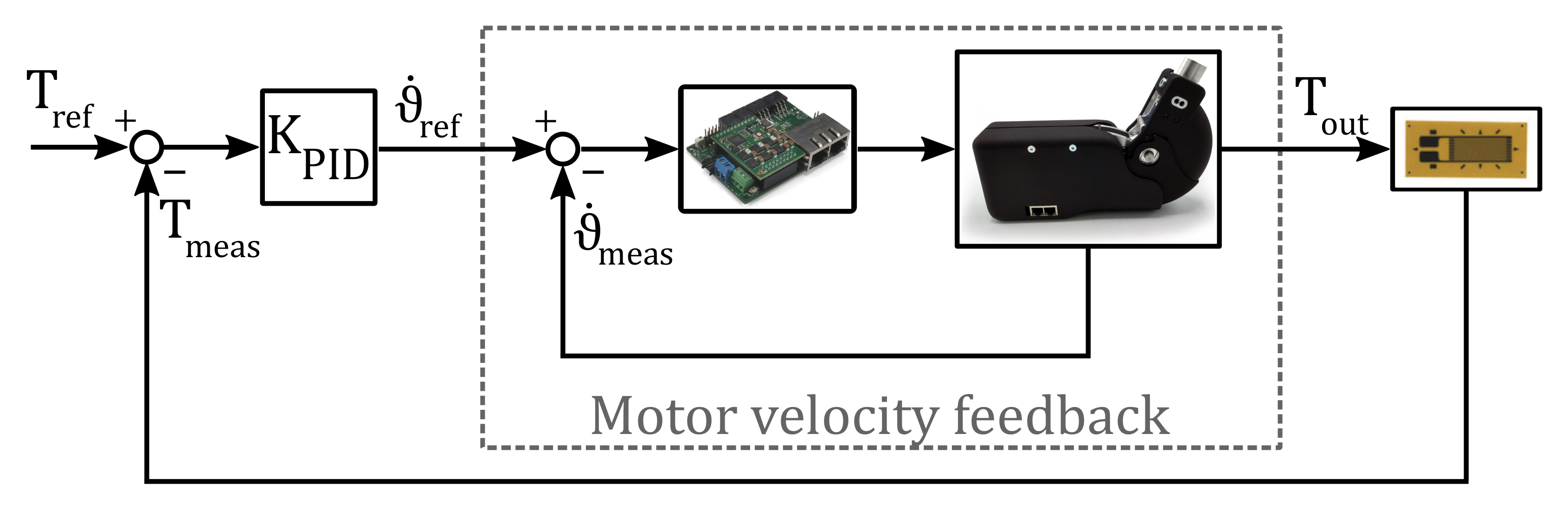
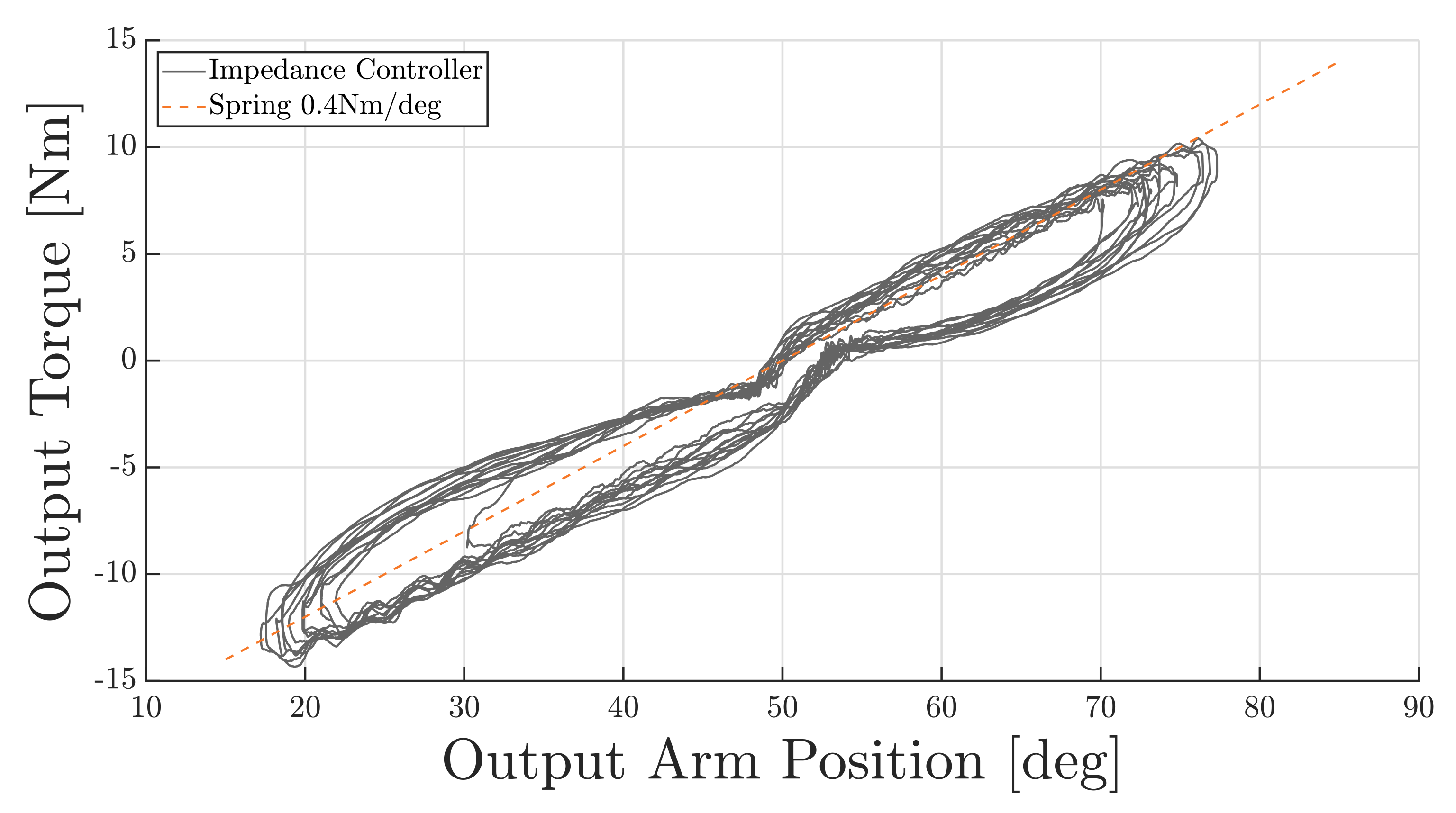
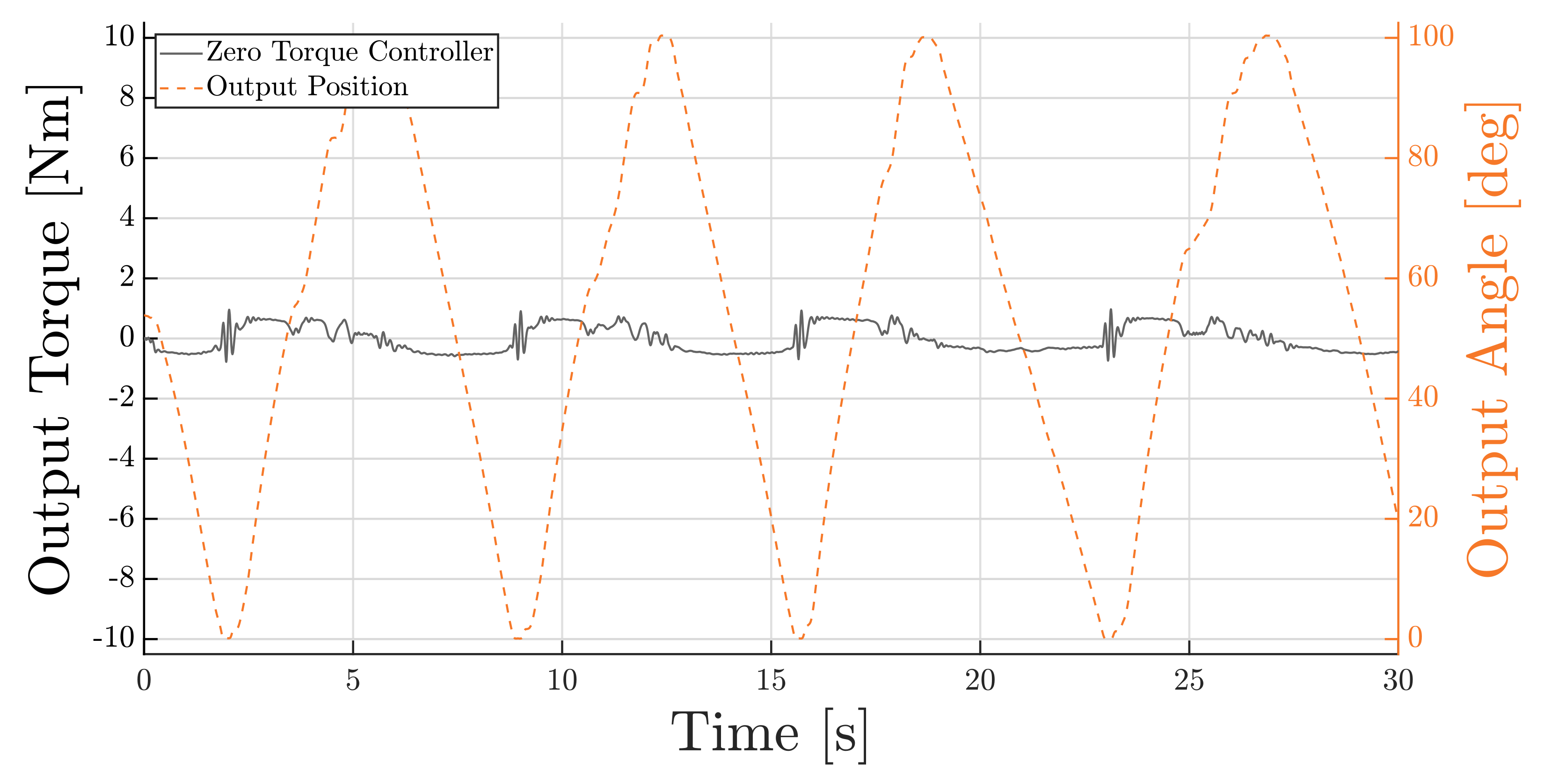
3.3. Case Study
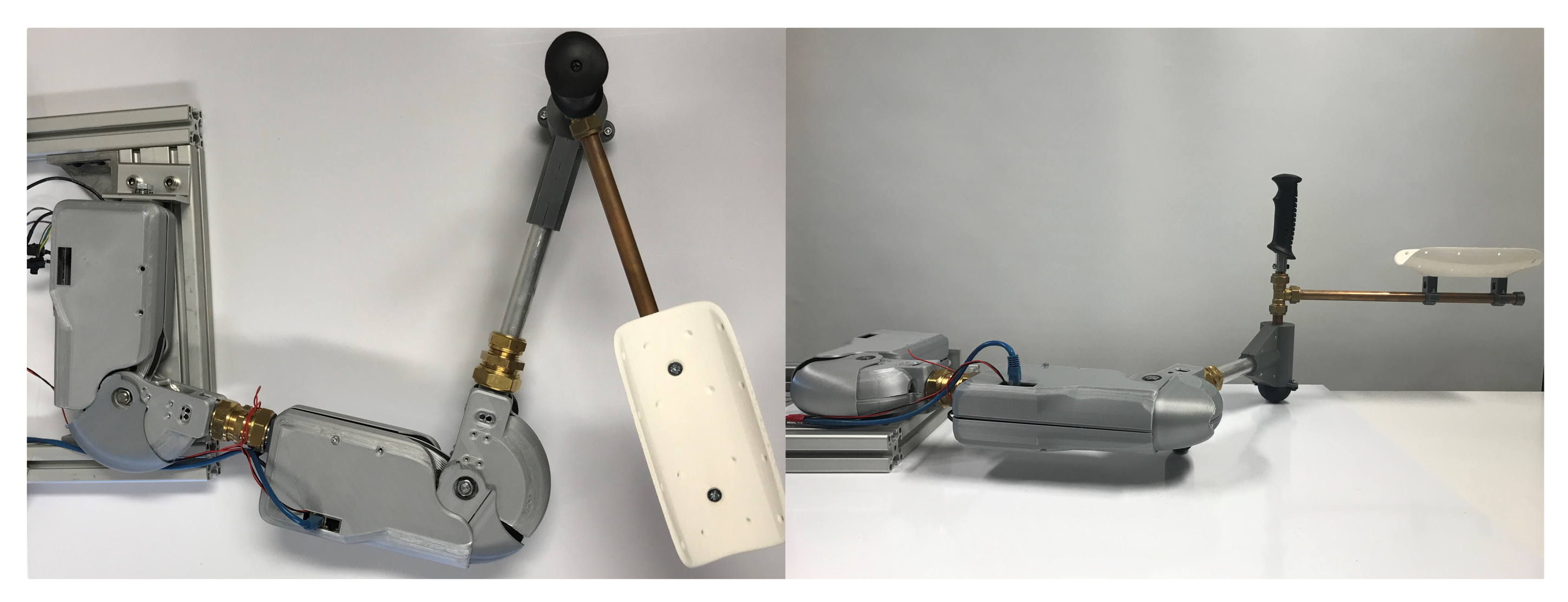
3.3.1. Arm Rehabilitation Device
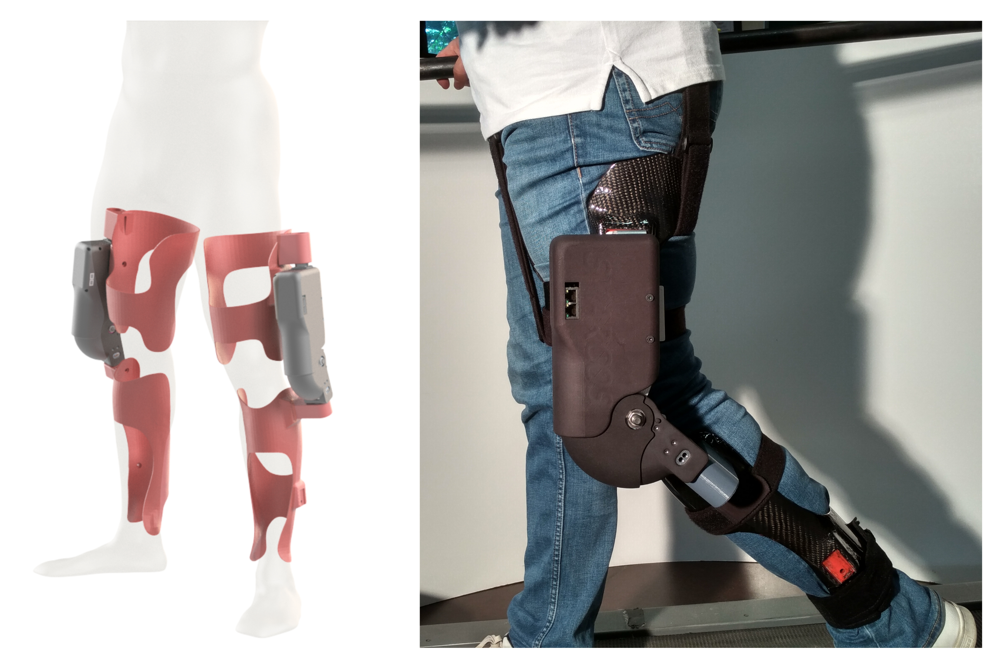
3.3.2. Active Knee Orthosis
4. Discussion
Comparison among VSA Systems
5. Conclusions and Future Works
Author Contributions
Funding
Institutional Review Board Statement
Informed Consent Statement
Data Availability Statement
Acknowledgments
Conflicts of Interest
Abbreviations
| ARES | Adjustable Rigidity with Embedded Sensor |
| AwAS | Actuator with Adjustable Stiffness |
| BAFSA | Bidirectional Antagonistic Floating Spring Actuator |
| BAVS | Bidirectional Antagonism with Variable Stiffness |
| CompAct-VSA | Compact Variable Stiffness Actuator |
| CSP | Cyclic Synchronous Position |
| FAS | Flexible Antagonistic Spring element |
| FSJ | Floating Spring Joint |
| HRI | Human–Robot Interactions |
| MACCEPA | Mechanically Adjustable Compliance & Controllable Equilibrium Position Actuator |
| MIRAD | an integrated Methodology to bring Intelligent Robotic Assistive Devices to the user |
| RoM | Range of Motion |
| SMARCOS | Smart Modular Actuator for Robotic Compliant Systems |
| SVSA | Smart Variable Stiffness Actuator |
| VSA-HD | Variable Stiffness Actuator based on Harmonic Drives |
References
- Goodrich, M. Human–Robot Interaction: A Survey. Found. Trends Hum.-Comput. Interact. 2007, 1, 203–275. [Google Scholar] [CrossRef]
- Veale, A. Towards compliant and wearable robotic orthoses: A review of current and emerging actuator technologies. Med. Eng. Phys. 2016, 38, 317–325. [Google Scholar] [CrossRef] [PubMed]
- Vanderborght, B. Variable impedance actuators: A review. Robot. Auton. Syst. 2013, 61, 1601–1614. [Google Scholar] [CrossRef] [Green Version]
- Cestari, M. An Adjustable Compliant Joint for Lower-Limb Exoskeletons. IEEE/ASME Trans. Mechatron. 2015, 20, 889–898. [Google Scholar] [CrossRef] [Green Version]
- Cestari, M. A New and Versatile Adjustable Rigidity Actuator with Add-on Locking Mechanism (ARES-XL). Actuators 2018, 7, 1. [Google Scholar] [CrossRef] [Green Version]
- Jafari, A. A Novel Intrinsically Energy Efficient Actuator With Adjustable Stiffness (AwAS). IEEE/ASME Trans. Mechatron. 2013, 18, 355–365. [Google Scholar] [CrossRef]
- Jafari, A. A New Actuator With Adjustable Stiffness Based on a Variable Ratio Lever Mechanism. IEEE/ASME Trans. Mechatron. 2014, 19, 55–63. [Google Scholar] [CrossRef]
- Torrealba, R. Design of variable impedance actuator for knee joint of a portable human gait rehabilitation exoskeleton. Mech. Mach. Theory 2017, 116, 248–261. [Google Scholar] [CrossRef]
- Petit, F. Bidirectional antagonistic variable stiffness actuation: Analysis, design & implementation. In Proceedings of the IEEE International Conference on Robotics and Automation (ICRA), Anchorage, AK, USA, 3–7 May 2010; pp. 4189–4198. [Google Scholar]
- Tsagarakis, N. A new variable stiffness actuator (CompAct-VSA): Design and modelling. In Proceedings of the 2011 IEEE/RSJ International Conference on Intelligent Robots and Systems, San Francisco, CA, USA, 25–30 September 2011; pp. 378–383. [Google Scholar]
- Friedl, W. FAS A flexible antagonistic spring element for a high performance over actuated hand. In Proceedings of the 2011 IEEE/RSJ International Conference on Intelligent Robots and Systems, San Francisco, CA, USA, 25–30 September 2011; pp. 1366–1372. [Google Scholar]
- Wolf, S. The DLR FSJ: Energy based design of a variable stiffness joint. In Proceedings of the 2011 IEEE International Conference on Robotics and Automation, Shanghai, China, 9–13 May 2011; pp. 5082–5089. [Google Scholar]
- Vanderborght, B. MACCEPA 2.0: Adjustable compliant actuator with stiffening characteristic for energy efficient hopping. In Proceedings of the 2009 IEEE International Conference on Robotics and Automation, Kobe, Japan, 12–17 May 2009; pp. 544–549. [Google Scholar]
- Brackx, B. Design of a modular add-on compliant actuator to convert an orthosis into an assistive exoskeleton. In Proceedings of the 5th IEEE RAS/EMBS International Conference on Biomedical Robotics and Biomechatronics, Sao Paulo, Brazil, 12–15 August 2014; pp. 485–490. [Google Scholar]
- Grosu, V. Design of Smart Modular Variable Stiffness Actuators for Robotic-Assistive Devices. IEEE/ASME Trans. Mechatron. 2017, 22, 1777–1785. [Google Scholar] [CrossRef]
- Catalano, M. VSA-CubeBot. A modular variable stiffness platform for multi degrees of freedom systems. In Proceedings of the 2011 IEEE International Conference on Robotics and Automation, Shanghai, China, 9–13 May 2011; pp. 5090–5095. [Google Scholar]
- Catalano, M. VSA-CubeBot. VSA-HD: From the enumeration analysis to the prototypical implementation. In Proceedings of the 2010 IEEE/RSJ International Conference on Intelligent Robots and Systems, Taipei, Taiwan, 18–22 October 2010; pp. 3676–3681. [Google Scholar]
- Marchal-Crespo, L. Review of control strategies for robotic movement training after neurologic injury. J. Neuroeng. Rehabil. 2009, 6, 1–15. [Google Scholar] [CrossRef] [PubMed] [Green Version]
- Riener, R. Patient-cooperative strategies for robot-aided treadmill training: First experimental results. IEEE Trans. Neural Syst. Rehabil. Eng. 2005, 13, 380–394. [Google Scholar] [CrossRef] [PubMed]
- Moltedo, M. Variable stiffness ankle actuator for use in robotic-assisted walking: Control strategy and experimental characterization. Mech. Mach. Theory 2019, 134, 604–624. [Google Scholar] [CrossRef]
- Bacek, T. Design and evaluation of a torque-controllable knee joint actuator with adjustable series compliance and parallel elasticity. Mech. Mach. Theory 2018, 130, 71–85. [Google Scholar] [CrossRef]
- Rossi, L.F. Design of a modular distributed control system for robotic exoskeletons. In Proceedings of the ISSNIP Biosignals and Biorobotics Conference: Biosignals and Robotics for Better and Safer Living (BRC), Manaus, Brazil, 9–11 January 2012; pp. 1–4. [Google Scholar]
- Slavnić, S. Mobile robotic gait rehabilitation system CORBYS-overview and first results on orthosis actuation. In Proceedings of the 2014 IEEE/RSJ International Conference on Intelligent Robots and Systems, Chicago, IL, USA, 14–18 September 2014; pp. 2087–2094. [Google Scholar]
- Vo-gia, L. Development of a 7DOF soft manipulator arm for the compliant humanoid robot COMAN. In Proceedings of the 2014 IEEE International Conference on Robotics and Biomimetics (ROBIO 2014), Bali, Indonesia, 5–10 December 2014; pp. 1106–1111. [Google Scholar]
- Van Ham, R. MACCEPA, the mechanically adjustable compliance and controllable equilibrium position actuator: Design and implementation in a biped robot. Robot. Auton. Syst. 2007, 10, 761–768. [Google Scholar] [CrossRef]
- Grosu, V. Multi-Axis Force Sensor for Human–Robot Interaction Sensing in a Rehabilitation Robotic Device. Sensors 2017, 17, 1294. [Google Scholar] [CrossRef]
- Winter, D. Biomechanics and Motor Control of Human Movement, 4th ed.; John Wiley & Sons: Hoboken, NJ, USA, 2009. [Google Scholar]
- Huysamen, K. Kinematic and kinetic functional requirements for industrial exoskeletons for lifting tasks and overhead lifting. Ergonomics 2020, 64, 818–830. [Google Scholar] [CrossRef] [PubMed]
- Grosu, V. Instrumenting Complex Exoskeletons for Improved Human–Robot Interaction. IEEE Instrum. Meas. Mag. 2015, 18, 5–10. [Google Scholar] [CrossRef]
- Grioli, G. Variable stiffness actuators: The user’s point of view. Sensors 2015, 34, 727–743. [Google Scholar] [CrossRef] [Green Version]
- Langlois, K. EtherCAT Tutorial: An Introduction for Real-Time Hardware Communication on Windows [Tutorial]. IEEE Robot. Autom. Mag. 2018, 25, 22–122. [Google Scholar] [CrossRef]
- Rosati, G. Planar Robotic Systems for Upper-Limb Post-Stroke Rehabilitation. ASME Int. Mech. Eng. Congr. Expo. 2008, 48630, 115–124. [Google Scholar]
- Flores, E. Improving patient motivation in game development for motor deficit rehabilitation. In Proceedings of the International Conference on Advances in Computer Entertainment Technology, Yokohama, Japan, 3–5 December 2008; pp. 381–384. [Google Scholar]


| Parameter | Value |
|---|---|
| Spring Stiffness K | 118.2 N/mm |
| Length (°) | 276.5 mm |
| Lever Arm Length B | 56 mm |
| Output Link Length C | 64.5 mm |
| Width | 60 mm |
| Weight | 1.4 kg |
| Speed Range [rpm] | Peak Back-Driving Torque [Nm] | |
|---|---|---|
| CW | CCW | |
| [0;5] | 1.43 | 1.60 |
| [5;10] | 1.88 | 1.83 |
| [10;20] | 2.32 | 2.65 |
| Parameter | Value |
|---|---|
| Peak Torque | 30 Nm |
| Max. Output Speed | 83 rpm |
| Active RoM | 0–104° |
| Weight (MACCEPA) | 1.4 kg |
| Weight (SMARCOS) | 1.7 kg |
| Actuator | Ref. | Weight | Peak Torque | Width | I/O |
|---|---|---|---|---|---|
| [kg] | [Nm] | [mm] | Protocol | ||
| ARES | [4] | 1.1 | 76 | 70 | CAN |
| ARES XL | [5] | 1.2 | 76 | 70 | I²C |
| AwAS | [6] | 1.8 | 80 | 130 | Ethernet |
| AwAS-II | [7] | 1.1 | 80 | 140 | Ethernet |
| BAFSA | [8] | 2.96 | 72 | 95 | - |
| BAVS | [9] | 0.75 | 8 | 56 | Spacewire |
| CompAct-VSA | [10] | 1.8 | 117 | - | - |
| FAS | [11] | 3.9 | 4.9 | 123.34 | Biss |
| FSJ | [12] | 1.4 | 67 | 118.55 | Spacewire |
| MACCEPA 2.0 | [13] | 2.4 | 70 | - | EtherCAT |
| MIRAD | [14] | 1.4 | 15 | 112 | EtherCAT |
| SVSA | [15] | 2.4 | 25 | 85 | EtherCAT |
| VSA-Cube | [16] | 0.26 | 3 | 58.5 | I²C |
| VSA-HD | [17] | 1.7 | 14 | 142 | CAN |
| SMARCOS | 1.7 (1.4) | 30 | 60 | EtherCAT |
Publisher’s Note: MDPI stays neutral with regard to jurisdictional claims in published maps and institutional affiliations. |
© 2021 by the authors. Licensee MDPI, Basel, Switzerland. This article is an open access article distributed under the terms and conditions of the Creative Commons Attribution (CC BY) license (https://creativecommons.org/licenses/by/4.0/).
Share and Cite
Ducastel, V.; Langlois, K.; Rossini, M.; Grosu, V.; Vanderborght, B.; Lefeber, D.; Verstraten, T.; Geeroms, J. SMARCOS: Off-the-Shelf Smart Compliant Actuators for Human–Robot Applications. Actuators 2021, 10, 289. https://doi.org/10.3390/act10110289
Ducastel V, Langlois K, Rossini M, Grosu V, Vanderborght B, Lefeber D, Verstraten T, Geeroms J. SMARCOS: Off-the-Shelf Smart Compliant Actuators for Human–Robot Applications. Actuators. 2021; 10(11):289. https://doi.org/10.3390/act10110289
Chicago/Turabian StyleDucastel, Vincent, Kevin Langlois, Marco Rossini, Victor Grosu, Bram Vanderborght, Dirk Lefeber, Tom Verstraten, and Joost Geeroms. 2021. "SMARCOS: Off-the-Shelf Smart Compliant Actuators for Human–Robot Applications" Actuators 10, no. 11: 289. https://doi.org/10.3390/act10110289
APA StyleDucastel, V., Langlois, K., Rossini, M., Grosu, V., Vanderborght, B., Lefeber, D., Verstraten, T., & Geeroms, J. (2021). SMARCOS: Off-the-Shelf Smart Compliant Actuators for Human–Robot Applications. Actuators, 10(11), 289. https://doi.org/10.3390/act10110289