Article

Control Design and Testing for a Finger Exoskeleton Mechanism

by
Adithya Prakash Damarla
1,*,
Matteo Russo
2 and
Marco Ceccarelli
1,*
1
Laboratory of Robot Mechatronics, University of Rome Tor Vergata, 00133 Rome, Italy
2
Faculty of Engineering, University of Nottingham, Nottingham NG81BB, UK
*
Authors to whom correspondence should be addressed.
Actuators 2022, 11(8), 230; https://doi.org/10.3390/act11080230
Submission received: 17 June 2022 / Revised: 15 July 2022 / Accepted: 8 August 2022 / Published: 10 August 2022
(This article belongs to the Special Issue Advanced Robots: Design, Control and Application)

Abstract

:
This paper describes a control strategy for a linkage finger exoskeleton mechanism with two degrees of freedom. To characterise the performance of the proposed finger motion assistance device, a replica of a human finger is prototyped to mimic human finger motion and to the testing effect of assistance provided by the novel exoskeleton with results from grasp tests. A feasible control design is developed to achieve a robust grasp of an object using the proposed exoskeleton mechanism, which is validated with simulated and experimental results that show how the proposed control algorithm maintains the force within 3% of the desired value. The aim of the paper is to present a control design for the ExoFinger exoskeleton with low-cost easy operation features that are aligned with the similar characteristics of the mechanical design.

1. Introduction

Nowadays, the loss of muscle strength in the fingers has become a common problem. Many factors can cause this kind of situation, such as ageing in the population or traumatising situations irrespective of age. Restoring full hand functionality is one of the most challenging aspects of stroke rehabilitation. Physiotherapists normally assist (or guide) patients in repetitive exercises and perform hand rehabilitation. However, the development of robotic rehabilitation systems in the last two decades has provided an alternative and efficient solution [1].
While early investigations use conventional robots to guide patients with an end-effector, rehabilitation and assistance exoskeletons have quickly become successful solutions [2]. As reported in a recent study on the topic in [3], finger motor recovery is significantly better with exoskeletons (97.3% recovery) when compared to end-effector rehabilitation guidance (48.3% recovery) or a control group with no robot assistance (4.4% recovery). Thus, a wide range of finger exoskeleton devices has been successfully developed in the last decades.
The state-of-the-art of an exoskeleton is to analyse the design and control, and representative examples can be classified according to degrees of freedom (DoF), actuation, motion transmission, and control technique. The prototype in [4,5], one of the few three-DoF designs, like most other designs is designed with underactuation for a more lightweight and compact solution. In this device, motion is guided by a geared transmission and actuated through cables, with force control obtained by measuring cable tension and a finger grasping force. The geared transmission is accurate but bulky, so that it could limit the usage of severely impaired patients. Moreover, the actuation is assembled on a heavy mounting plate, making this design neither wearable nor portable. Other fully actuated designs aim at improving user experience by avoiding bulky external motor packs, such as the linkage with on-finger servomotors and EMG-based closed-loop control like in [6], or by employing a wearable jointless design that drives the phalanx directly through cables like in [7]. Finally, the three-DoF design in [8] proposes an interesting solution with push/pull compliant rods driven by DC linear servomotors for a lean and lightweight transmission system, albeit with a bulky static actuation pack.
Designs with two DoFs are leaner than the other solution, thanks to one less active DoF and respective motor(s). The example in [9] uses a linkage for motion transmission, relying on cables for actuation. Closed-loop control is achieved by torque feedback on the cables’ series elastic actuators that are remotely located in a static actuation pack. Whereas most exoskeleton prototypes are designed for a single finger size, a few adjustable designs have also been presented, such as the two-DoF cable-driven linkage [10]. A third two-DoF cable-driven linkage is reported in [11,12], with the closed-loop control with a flexible Force Sensitive Resistor sensor (i.e., FSR) on a phalanx. At the same time, all the previous two-DoF examples rely on a static motor pack. Such as, the linkage in [13] is actuated by a linear motor on the wrist and forearm.
Whereas three-DoF designs can be the solution accurate and two-DoF exoskeletons ensure some motion support with comfort, the one-DoF solution represents the most wearable design. However, given their reduced flexibility, more effort is needed in the design phase or control algorithm to achieve a performance comparable to one of their more complex alternatives. A deeper insight into control is provided in [14], where muscle electrical signals (EMG sensors), brain-computer interfaces, and speech recognition provide an advanced user experience with a one-DoF linkage driven by a single stepper motor. Another one-DoF linkage is proposed in [15,16], controlled by a DC motor with force control; however, the bulky design can hinder patient motion and limit everyday usage. The design in [17] provides better force assistance with pneumatic actuation but is bulky and limited in motion guidance. A deeper insight into the effect of underactuation is provided in the investigation in [18]. The two linkages in [19,20] only guide the first phalanx, with a linear motor on the wrist and an on-hand servomotor. A linkage driven by linear motors, guiding only the fingertip, is proposed in [21] to achieve variable stiffness. A last one-DoF example in [22] uses geared linkage transmission for an accurate motion, achieving admittance control with a pressure sensor at the fingertip.
The application of all these designs is finger rehabilitation. However, finger exoskeletons can be developed for other functions, as shown by the haptic gloves [23,24]. Overall, the main trends that can be observed in the analysed literature can be summarised as the following:
  • Degrees of Freedom: Most finger exoskeletons have one, two, or three DoFs. Exoskeletons with three DoFs are characterised by a fully guided motion capability and active control of the position of each phalanx of a finger. Exoskeletons with one DoF maintain active control of the first phalanx (the phalanx with the wider motion range) or the fingertip (passively forcing motion in all three phalanxes). Exoskeletons usually possess active control on the third phalanx with two DoFs. However, as restoring motion in the first and second phalanxes of the finger is usually deemed more critical, some exoskeletons with two DoFs actively control the fingertip and either the first or second phalanx with convenient design or control architecture.
  • Actuation: Most finger exoskeletons favor electric motors (DC, stepper, servo). These motors can be embedded in the finger or remotely placed on the wrist or in a dedicated static actuation unit. The embedded solution would be ideal, but the weight and bulk of most actuation force units use static or uncomfortable wrist-worn actuators. This situation limits the usage of these exoskeletons to static exercising, potentially discouraging continuous or semi-continuous use that would benefit the patient in a diary usage.
  • Transmission: since the motors cannot act directly on the finger joints, a mechanical transmission is required to achieve the desired motion. This transmission is commonly based on linkages and gears; cable-driven mechanisms enable remote actuation (cables).
  • Feedback: There is no consensus on the best closed-loop control method for finger exoskeletons since different designs and sensing solutions achieve similar performance. Some solutions prefer a more straightforward design with force/torque control at the motor level, closing the loop on actuation variables and using feed-forward models to consider the transmission. Other designs place force sensors (e.g., force-sensing resistors, strain gauges, or pressure sensors) at the interface between the mechanism and the patient to measure the actual force exerted on the finger. A third solution is represented by muscle electrical signal sensors (i.e., EMG sensors) that aim to close the loop through the patients’ reactions.
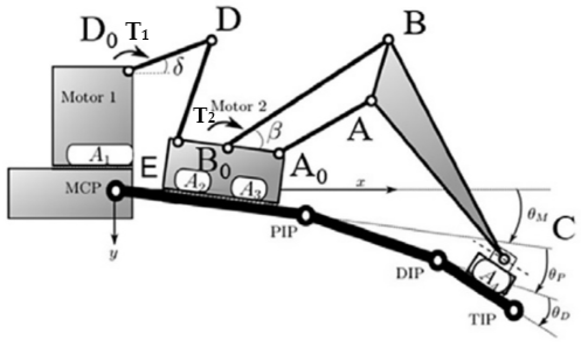
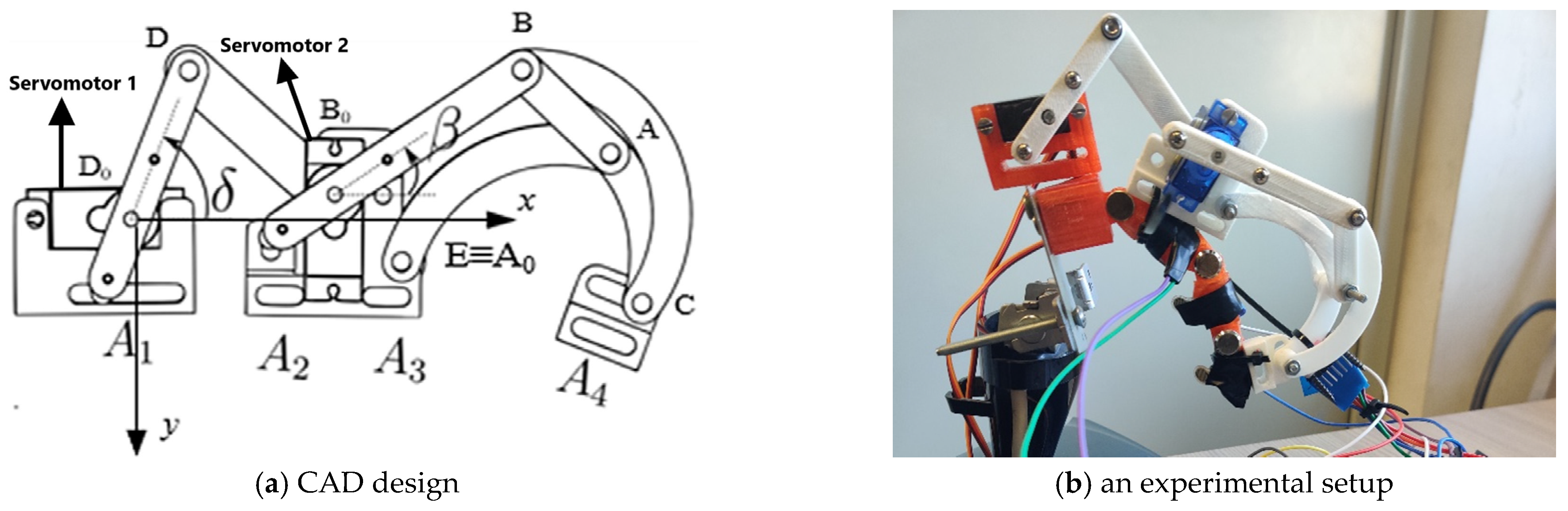
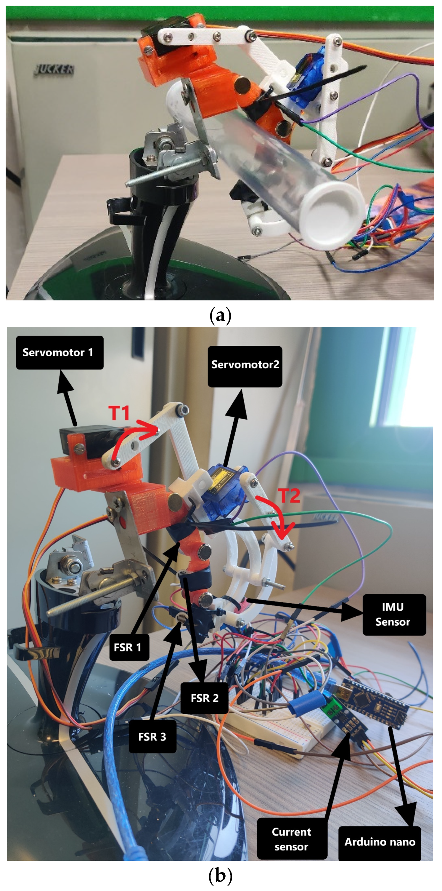
In recent developments, a finger exoskeleton (ExoFinger) as in [25,26,27,28] has been developed to address a significant gap in this literature: most works aim at a highly constrained, accurate motion, with a demonstration on single patients or a limited control group. However, to enable the widespread use of this technology, a finger exoskeleton should address user comfort and be able to adapt to different finger sizes. However, out of all the examples presented, only [10] can adapt to variable finger dimensions and only in a limited way. Furthermore, regarding comfort, only [6] is a truly wearable design, with all the actuation embedded in the exoskeleton mechanisms. In contrast, other designs use large wrist- or hand-mounted or static actuation packs. For this reason, ExoFinger was proposed with a compact design that can only be worn on the finger and can be adapted to different hand sizes [25,26].
In previous works, the ExoFinger design has been kinematically and statically characterised as reported in [27,28], with experimental tests on motion tracking, power consumption estimation, and muscle activity tracking through EMG sensors. However, a control strategy for this mechanism has not been introduced in past works. As per a compact, wearable, and low-cost design, expensive or large sensors and actuators cannot be used, preventing the implementation of high-performance but complex control strategies. For this reason, this paper aims to improve ExoFinger’s performance by developing an easily operated and sufficiently robust control scheme that ensures proper functioning and assistance in grasping within the system’s hardware constraints and limitations.

2. ExoFinger

The proposed finger exoskeleton, ExoFinger, is designed and prototyped in PLA with a FDM 3D printer. ExoFinger is actuated with the help of two servomotors to drive the mechanism. This arrangement is illustrated in the kinematic diagram in Figure 1, whereas the mechanical design of the ExoFinger mechanism with the main parameters are illustrated in Figure 2, which also describes the angular position of the servomotors and shows the prototype used for the reported experiences. The angular position of Servomotor 1 is represented as δ in the xy reference frame. Servomotor 1 can produce a maximum torque of 0.275 Nm in a clockwise direction, defined as T1 in Figure 1.
Servomotor 2 also controls an angular position β with the horizontal axis as a reference, as shown in Figure 2a. The servomotor 2 produces a maximum torque of 0.18 N-m as T2 in a clockwise direction, represented in Figure 1. The dimensions of the exoskeleton are tabulated in Table 1.
In previous work, the kinematics and statics of the proposed finger exoskeleton were analysed, but only motion control was employed in the experiments, similarly to [29]. Since this lack of feedback can cause grasping exercises to fail, the grasped objects could slip away from the finger. Moreover, the system could grasp objects too tightly. This situation may damage a grasped object or cause a failure of the mechanism while performing a grasp of an object. These issues can be solved by developing a suitable closed-loop force control algorithm for the finger exoskeleton, by reacting to either motor torque [30,31] or reaction force [32] feedback. For this reason, this paper shows the implementation of a control algorithm with FSR (Force Sensitive Resistors) sensors.

3. Conceptual Design
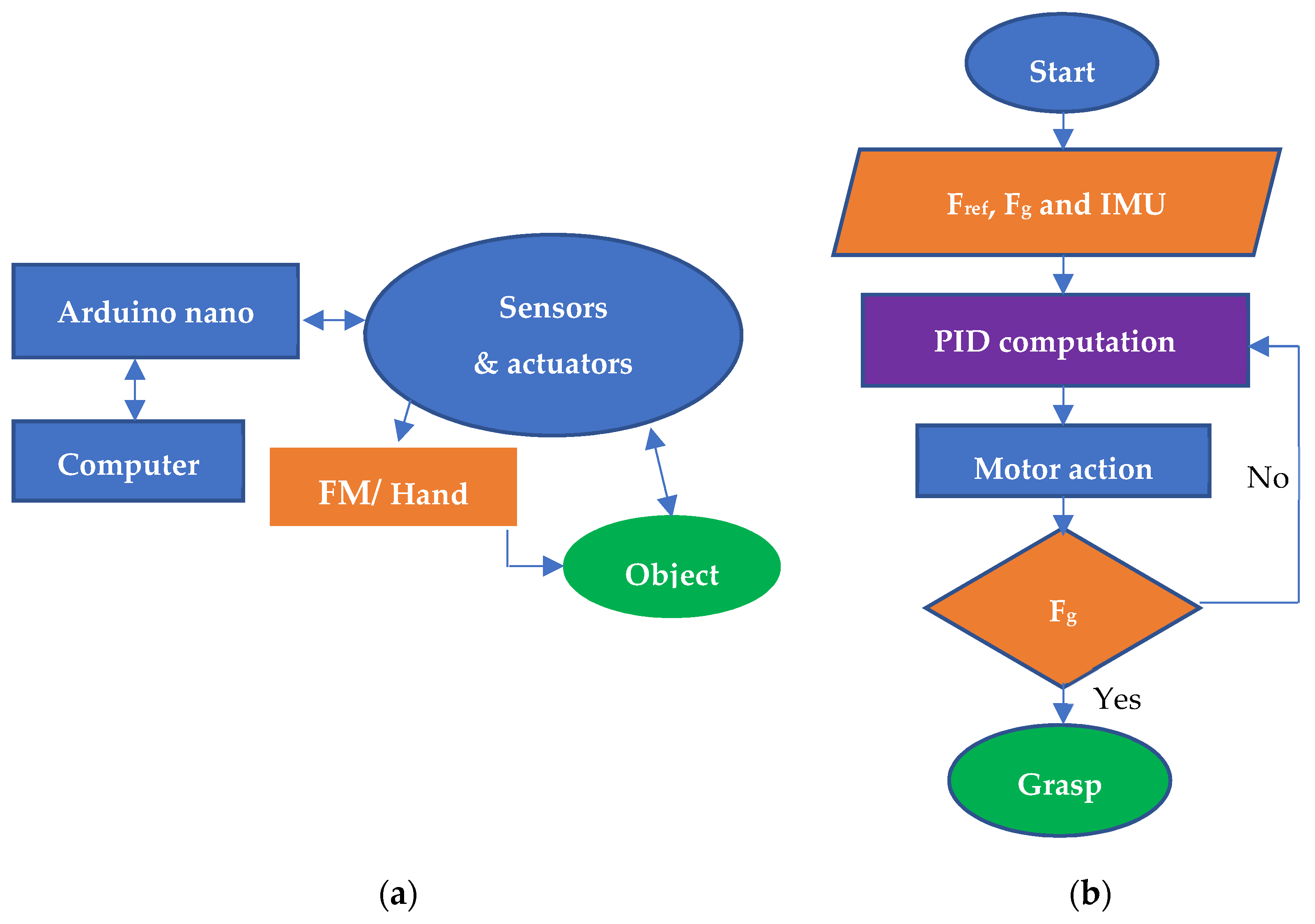
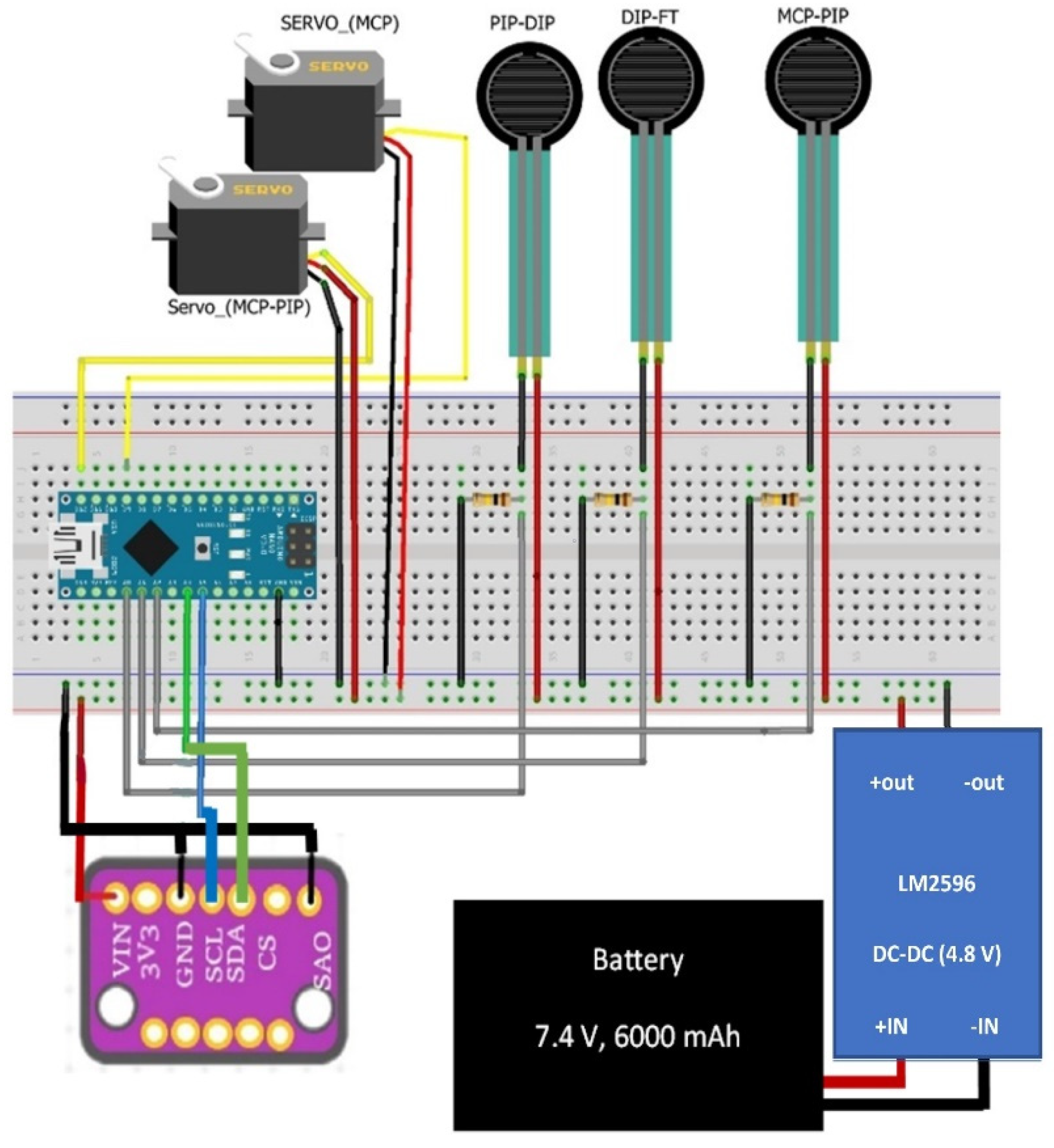
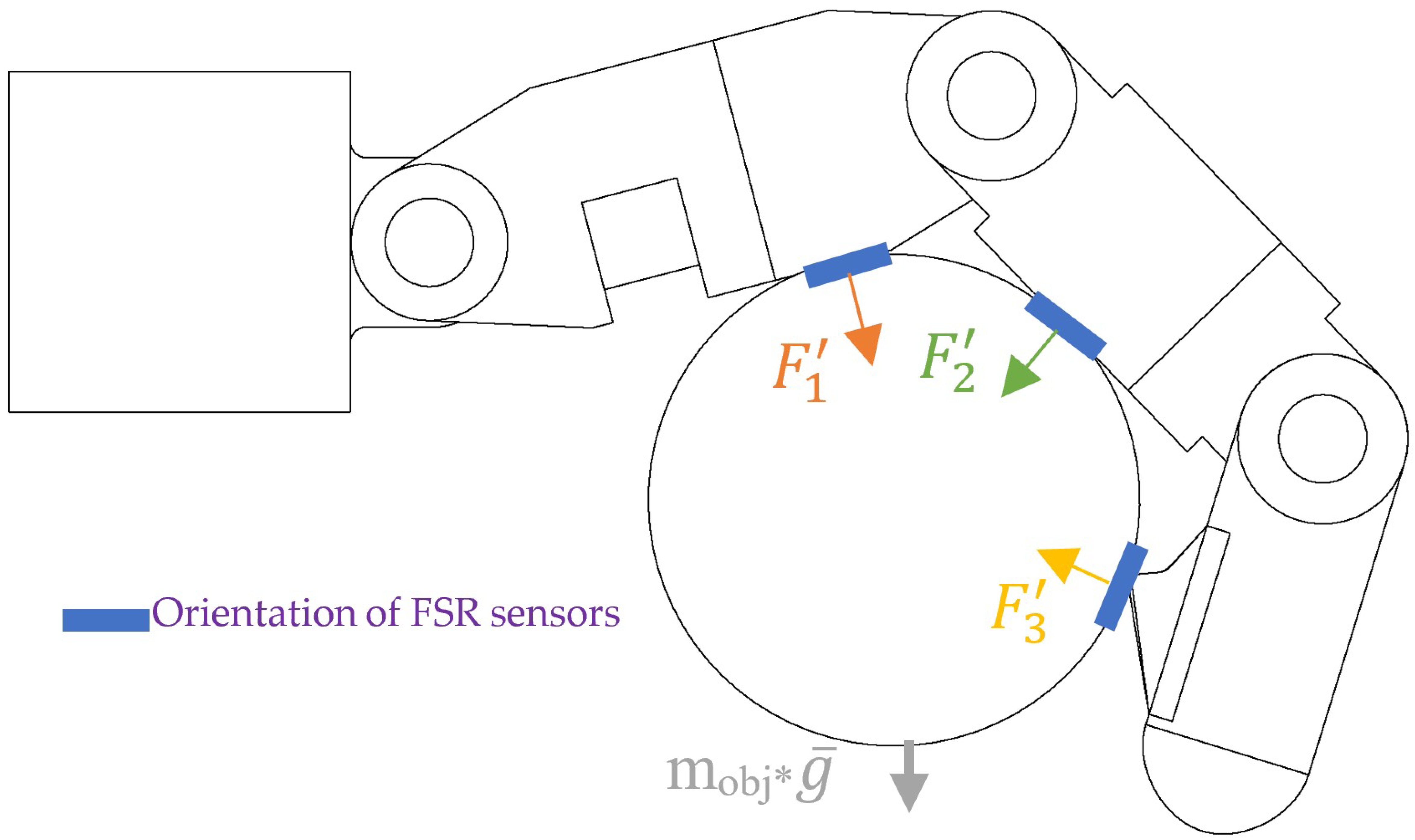
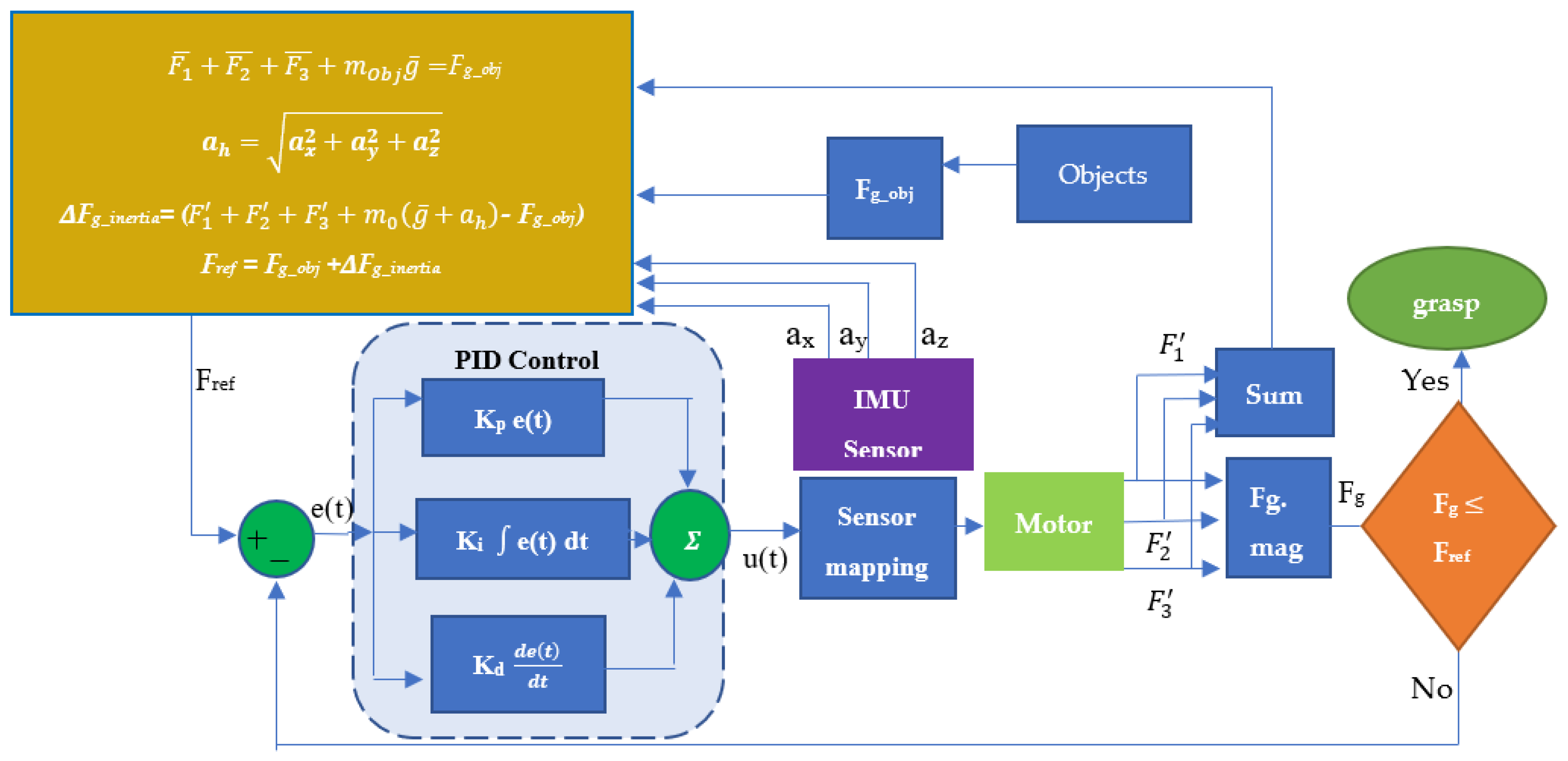
As shown in previous research work [27,28], ExoFinger is a two-degree-of-freedom mechanism that proved feasible in providing motion assistance for either rehabilitation or support tasks. Despite the lack of sensing and low-cost actuation, the original prototype already shows a good capability to constrain (for rehabilitation) and assist (in support tasks) a human finger. The main objective of this research is to further improve performance by implementing an adaptive grasp strategy through a new control design, as outlined in Figure 3. This control scheme provides better motion assistance to the finger guided by ExoFinger by adapting the action of the actuators to the feedback from the FSR force sensor according to the required degree of assistance the user needs. The adaptive grasping is examined and validated using an artificial average-sized human finger replica built in a FDM 3D printer with (Polylactic Acid) PLA as a filling material. This artificial finger, called the finger mechanism (FM), has three degrees of freedom to replicate the action of a human finger by grasping an object while guided by the proposed finger exoskeleton mechanism.
Figure 3a describes the general interaction layout using FM or hand to acquire the data from the sensors and actuators using an Arduino Nano. In addition, this interaction layout enables a conceptual control design layout, as shown in Figure 3b. Finally, these interactions and conceptual layouts make it possible to design an electric circuit, as shown in Figure 4. In this circuit design, the key components are an Arduino Nano (Atmega328), two servomotors, force-sensitive resistors (FSR), battery, and LM2596 DC-DC (4.8 V) to drive the ExoFinger mechanism, as previously shown in Figure 2. The Force Sensitive Resistors (FSR) will sense the force while grasping an object with FM. The FSR sensors are placed on the FM phalanges, as shown later in Figure 5. An IMU sensor will sense the position and acceleration of ExoFinger while the exoskeleton grasps an object. Onboard power avoids Arduino’s current limitations while making the proposed finger exoskeleton a fully wearable device.

4. Control Design

For a fairly simple and efficient solution to satisfy operational requirements for a low-cost, easily operated solution, a PID controller has been selected. Since the PID controller is not model-based, it does not require system parameters or a system model to control the input signal. An average grasping force Fg is obtained from the three FSR sensors, as shown in Figure 5, while grasping an object. The acquired contact forces F 1 ,   F 2   and   F 3 are sent to the controller to evaluate Fg as
F g = ( F 1 ) 2 + ( F 2 ) 2 + ( F 3 ) 2
This value is compared to the target grasping force Fref; then, according to the control design scheme in Figure 6, the controller performs the required control action for every grasp iteration. The force reference Fref is generated iteratively to handle both the weight of the object (represented by Fg_obj  = m o b j g ¯ ) and inertial effects Fg_inertia to achieve grasp, and is expressed as
F r e f = F g _ o b j + F g _ i n e r t i a = m o b j ( g ¯ + a h )
An inertial measurement unit (IMU) helps to compensate for the inertia effect by measuring the acceleration a h during operation, to obtain Fref dynamically. The inertia compensation maintains the object in equilibrium position as in the following vectorial equation:
F 1 + F 2 + F 3 + m o b j ( g ¯ + a h ) = 0
With reference to Figure 6, the difference between the measured contact force at the fingertips (as per Figure 5) and the required grasping force is thus fed into a PID controller that calculates, as output, the needed motor motion for both motors to increase or decrease grasping force. This computation is performed by the sensor mapping function, which is obtained through the dynamic model of the mechanism and directly maps the controller response to the angle of the servo motor shaft. As mentioned beforehand, the force reference is iteratively computed with the help of an IMU sensor to measure the components of the system’s acceleration, which are combined to evaluate the acceleration magnitude.
The normal reaction force of an object helps set maximum limitations to avoid the finger’s failure while grasping an object. The difference between force reference Fref and grasping force Fg = ( F 1 ) 2 + ( F 2 ) 2 + ( F 3 ) 2 generates an error input for the controller while grasping an object. The control increments the actuation angle of the servomotors. This open-loop action of servomotors which enables to produce a closed-loop feedback action. The controller uses a mapping function between FSR sensors and servomotors. This closed-loop control action prevents squeezing or damaging a grasping object.
The proper gain values can be tuned by keeping the proportional and derivative controller errors close to zero to follow the reference force. The control design gives input response as U(t). Kp, Ki, and Kd are the gains of Proportional, Integral, and Derivative controllers, respectively. Uro is the unknown constant input. This unknown constant input is a calibration value obtained from the human hand grasping calibration using FSR sensors. The equations are illustrated as follows:
U ( t ) = K p .   e ( t ) + K d   d dt   e ( t ) + u r 0 ( t )
d dt U r = k i ( F . r e f   F g )
  d   U r = K i   ( F . r e f   F g )   dt
Therefore, u r ( 0 ) = u r 0
u r 0 = k i   ( F . r e f F g )   dt
u r 0 = k i   ( F . r e f )   dt .
Substituting Equation (8) into Equation (3), it is possible to establish an integral action that provides the desired response of the PID controller.

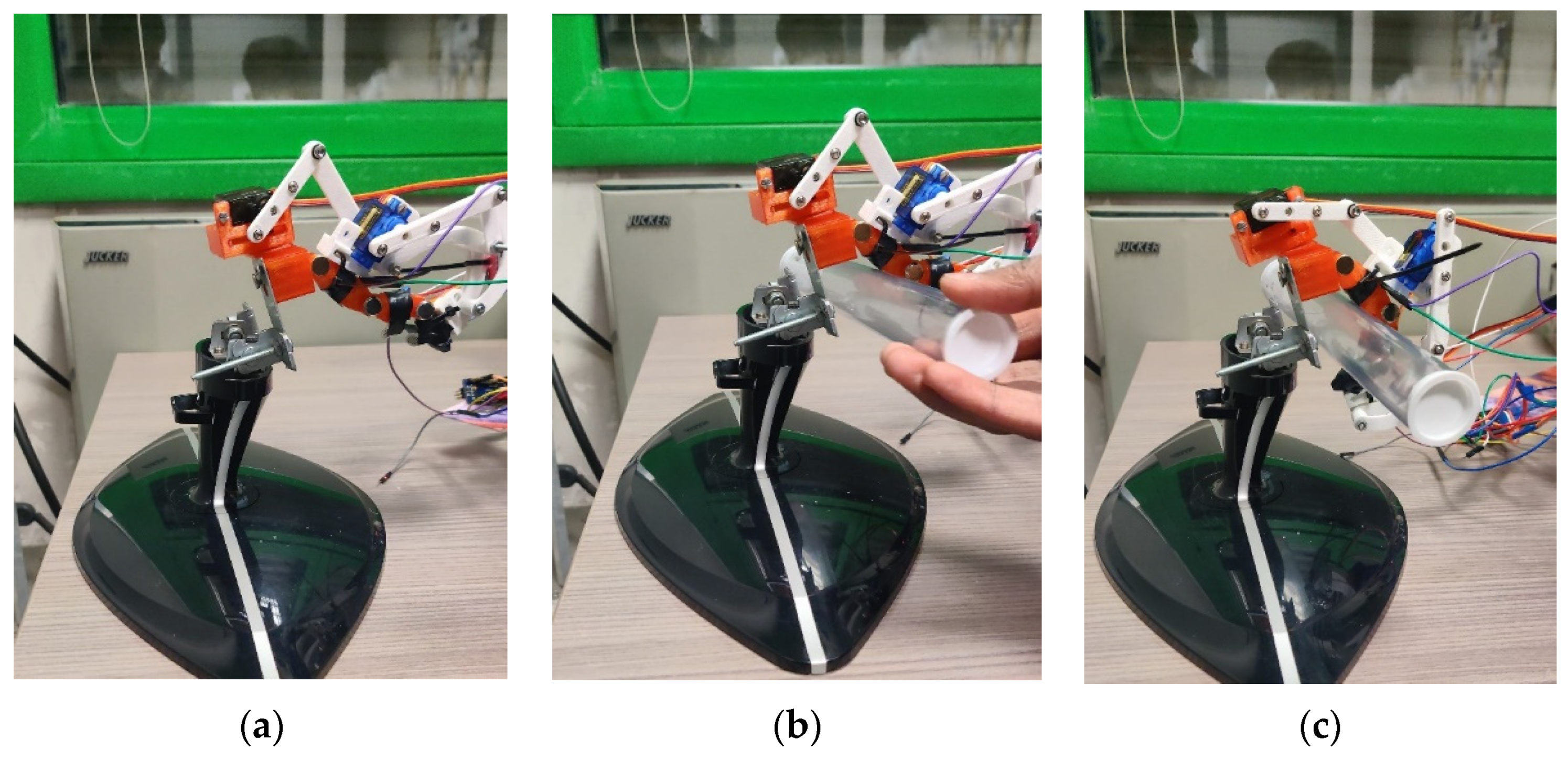
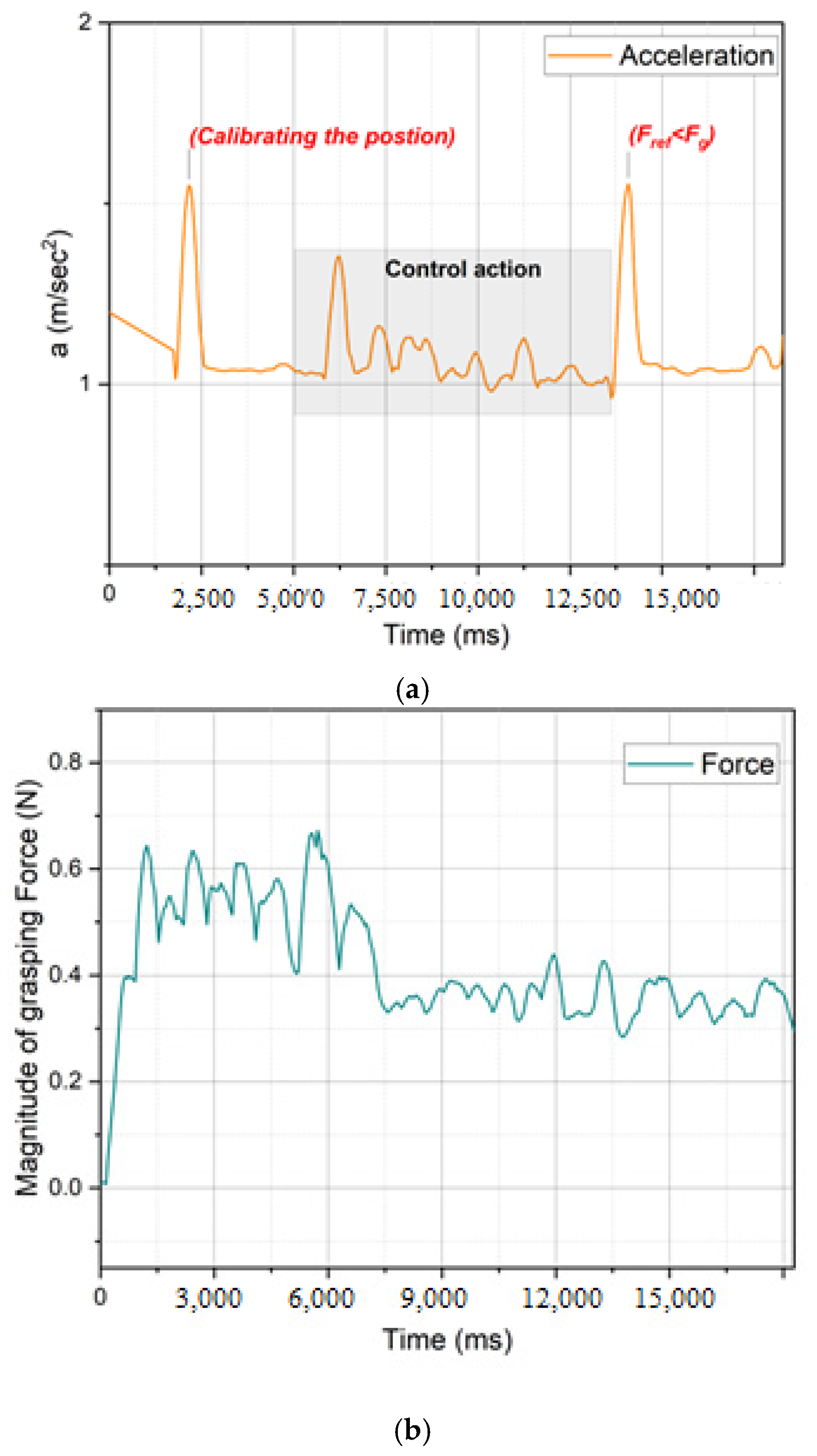
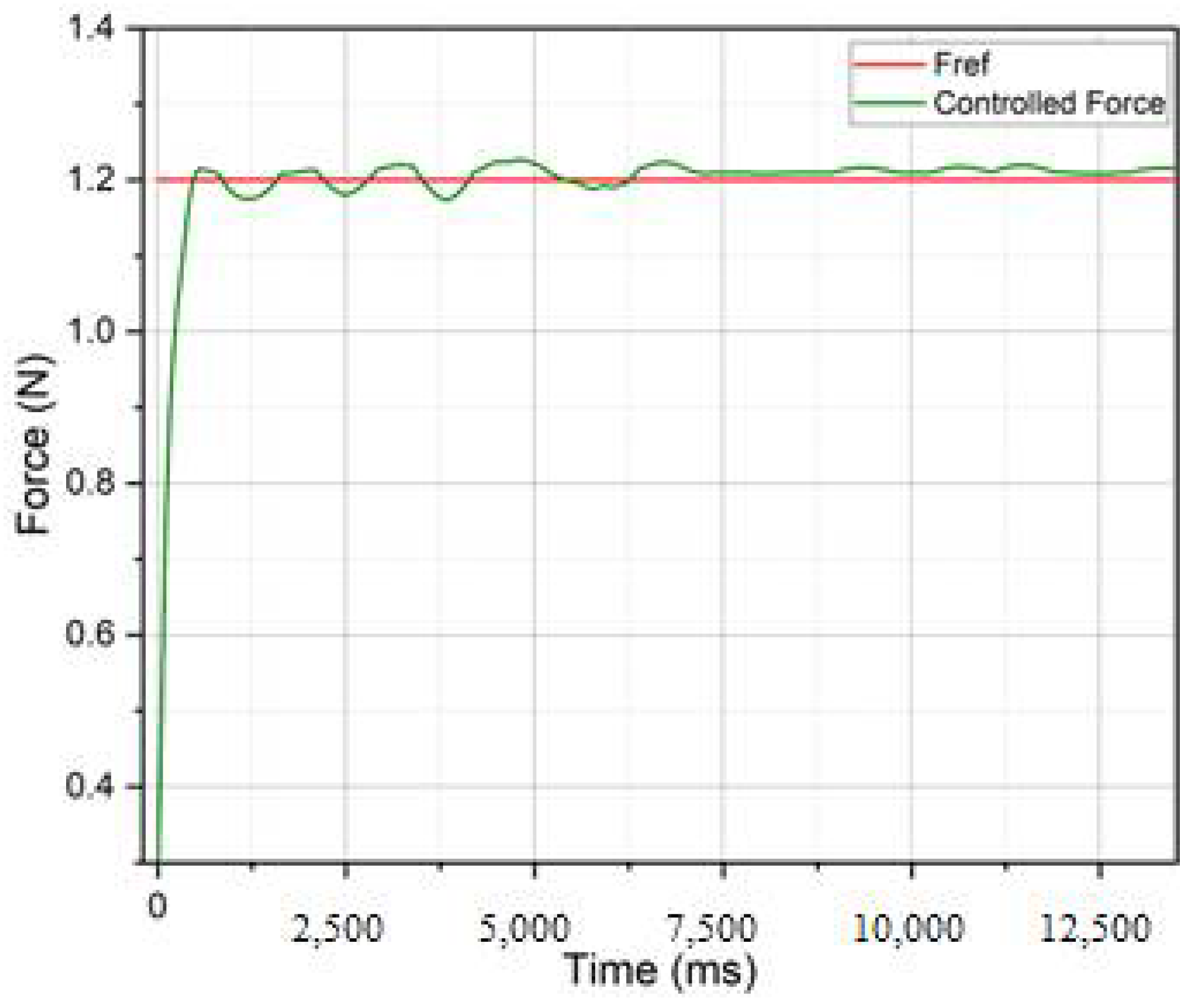
5. Experimental Results

The proposed controller has been tested in grasping experiments to prove the feasibility of this control algorithm in achieving a robust grasp operation with the proposed exoskeleton mechanism. The prototype has been built with the components illustrated in Table 2, and the prototype setup is shown in Figure 7a. The test was performed by grasping a stiff cylindrical item with the FM assisted by ExoFinger, as shown in Figure 7b.
The gain tuning is crucial in obtaining the controller’s desired output response. Table 3 lists gains corresponding to the obtained results with ExoFinger through experimental calibration, so that they allow the ExoFinger to hold a single object within a desired force, with a target maximum overshooting of 10% allowed so as not to damage the manipulated object.
In Figure 8, the ExoFinger is shown performing a grasping sequence with a rigid cylindrical object weighing 25 g. The object’s dimensions are 207 mm in length and 32 mm in diameter. The proposed design example of ExoFinger can assist in holding objects with a width ranging from 32 to 38 mm. The maximum payload depends on servomotors’ torque, equal to 3.06 kg for the reported prototype. This value is higher than the payload of an average human finger. It shows how ExoFinger can assist in rehabilitation tasks and support healthy individuals in high-payload manipulation. The grasping sequence in Figure 8 is here reported as a numerical example to characterise controller performance while performing a grasp.
In the first numerical result, the system’s performance is characterised by the magnitude of acceleration and grasping force. The acceleration plot in Figure 9a describes the magnitude of acceleration as represented in Equation (5) and Figure 6, while the exoskeleton finger performs the grasp of an example object. In the same plot, a first peak represents the moment when the IMU sensor is calibrated. This peak indicates ExoFinger setting up the initial position, as represented in Figure 8a, and subsequent acquisitions indicate how the control action performs a successful grasp with force feedback illustrated in Figure 9a. Whenever the magnitude of grasping force does not reach the force reference, the ExoFinger servomotors act to compensate for this action, relying on the feedback from the FSR sensors. However, it has been observed that the FSR sensors could provide unreliable information with a rigid cylindrical surface as the contact only happens along a line, causing the oscillation of the acquired data as observed in Figure 10. Future developments might want to address this by implementing more accurate sensing solutions. Nevertheless, the PID controller always shows a good performance as the proposed finger exoskeleton always manages to maintain and provide the required force in real time, stabilizing slightly above the needed action (Fref < Fg). These results are obtained with a sample acquisition rate of 200 Hz and time response of 50 milliseconds and show that the proposed algorithm can maintain the force within 3% of the desired value. While the performance is here characterised with grasping force and error (i.e., displacement from the desired value), further evaluations will be implemented in future works with a wider range of criteria as suggested for example in [35,36].

6. Conclusions

This paper presents a control design for ExoFinger, a finger exoskeleton. The linkage design and motion assistance give specific indicators for requirements for a controlled operation in human and human-mimicked manipulative actions. The proposed PID control law is implemented in the prototype through force sensors and inertial measurement units to acquire both grasping force and acceleration. The proposed hardware solution preserves the low-cost, easy-to-use operation, and portability of the ExoFinger mechanical design. Laboratory tests with an artificial finger verify the feasibility of the proposed controller and characterise its performance. The current prototype shows a good performance for a two-DoF low-cost wearable exoskeleton with an efficient control scheme; however, a more flexible control architecture could further improve performance. As such, future works can be planned to improve the control design to support and demonstrate a larger variety of grasping modes and increase adaptability to a wider range of objects to be grasped. Furthermore, new formulations and models to include considerations on safety factors (by FEM analysis or dynamic simulations) and the compliance between the exoskeleton and a patient finger will provide a safety evaluation for the application to human users, for either exercising or rehabilitation.

Author Contributions

Conceptualisation, M.C. and A.P.D.; methodology, M.C. and A.P.D.; software, A.P.D. validation, M.C., A.P.D. and M.R.; formal analysis, M.C., A.P.D. and M.R.; investigation, M.C., A.P.D. and M.R.; resources, M.C.; data curation, A.P.D.; writing—original draft preparation, M.C. and A.P.D.; writing—review and editing, M.C., A.P.D. and M.R.; visualisation, A.P.D.; supervision, M.C.; project administration, M.C.; funding acquisition, M.C. All authors have read and agreed to the published version of the manuscript.

Funding

This research received no external funding.

Institutional Review Board Statement

Not applicable.

Informed Consent Statement

Not applicable.

Data Availability Statement

Not applicable.

Conflicts of Interest

The authors declare no conflict of interest.

References

  1. Yue, Z.; Zhang, X.; Wang, J. Hand rehabilitation robotics on poststroke motor recovery. Behav. Neurol. 2017, 2017, 3908135. [Google Scholar] [CrossRef] [PubMed]
  2. Balasubramanian, S.; Klein, J.; Burdet, E. Robot-assisted rehabilitation of hand function. Curr. Opin. Neurol. 2010, 23, 661–670. [Google Scholar] [CrossRef] [PubMed]
  3. Moggio, L.; de Sire, A.; Marotta, N.; Demeco, A.; Ammendolia, A. Exoskeleton versus end-effector robot-assisted therapy for finger-hand motor recovery in stroke survivors: Systematic review and meta-analysis. Top. Stroke Rehabil. 2021, 1–12. [Google Scholar] [CrossRef] [PubMed]
  4. Worsnopp, T.T.; Peshkin, M.A.; Colgate, J.E.; Kamper, D.G. An actuated finger exoskeleton for hand rehabilitation following stroke. In Proceedings of the 2007 IEEE 10th International Conference on Rehabilitation Robotics, Noordwijk, The Netherlands, 13–15 June 2007; pp. 896–901. [Google Scholar] [CrossRef] [Green Version]
  5. Jones, C.L.; Wang, F.; Morrison, R.; Sarkar, N.; Kamper, D.G. Design and development of the cable actuated finger exoskeleton for hand rehabilitation following stroke. IEEE/Asme Trans. Mechatron. 2012, 19, 131–140. [Google Scholar] [CrossRef] [PubMed]
  6. Ngeo, J.; Tamei, T.; Shibata, T.; Orlando, M.F.; Behera, L.; Saxena, A.; Dutta, A. Control of an optimal finger exoskeleton based on continuous joint angle estimation from EMG signals. In Proceedings of the 2013 35th Annual International Conference of the IEEE Engineering in Medicine and Biology Society (EMBC), Osaka, Japan, 3–7 July 2013; pp. 338–341. [Google Scholar]
  7. Yang, J.; Xie, H.; Shi, J. A novel motion-coupling design for a jointless tendon-driven finger exoskeleton for rehabilitation. Mech. Mach. Theory 2016, 99, 83–102. [Google Scholar] [CrossRef]
  8. Li, C.; Yan, Y.; Ren, H. Compliant finger exoskeleton with telescoping super-elastic transmissions. J. Intell. Robot. Syst. 2020, 100, 435–444. [Google Scholar] [CrossRef]
  9. Agarwal, P.; Fox, J.; Yun, Y.; O’Malley, M.K.; Deshpande, A.D. An index finger exoskeleton with series elastic actuation for rehabilitation: Design, control and performance characterisation. Int. J. Robot. Res. 2015, 34, 1747–1772. [Google Scholar] [CrossRef]
  10. Wang, J.; Li, J.; Zhang, Y.; Wang, S. Design of an exoskeleton for index finger rehabilitation. In Proceedings of the 2009 Annual International Conference of the IEEE Engineering in Medicine and Biology Society, Minneaplolis, MN, USA, 3–6 September 2009; pp. 5957–5960. [Google Scholar]
  11. Sun, N.; Li, G.; Cheng, L. Design and validation of a self-aligning index finger exoskeleton for post-stroke rehabilitation. IEEE Trans. Neural Syst. Rehabil. Eng. 2021, 29, 1513–1523. [Google Scholar] [CrossRef] [PubMed]
  12. Li, G.; Cheng, L.; Sun, N. Design, manipulability analysis and optimisation of an index finger exoskeleton for stroke rehabilitation. Mech. Mach. Theory 2022, 167, 104526. [Google Scholar] [CrossRef]
  13. Hernández-Santos, C.; Davizón, Y.A.; Said, A.R.; Soto, R.; Felix-Herrán, L.C.; Vargas-Martínez, A. Development of a Wearable Finger Exoskeleton for Rehabilitation. Appl. Sci. 2021, 11, 4145. [Google Scholar] [CrossRef]
  14. Hsu, T.H.; Chiang, Y.C.; Chan, W.T.; Chen, S.J. A finger exoskeleton robot for finger movement rehabilitation. Inventions 2017, 2, 12. [Google Scholar] [CrossRef] [Green Version]
  15. Ertas, I.H.; Hocaoglu, E.; Barkana, D.E.; Patoglu, V. Finger exoskeleton for treatment of tendon injuries. In Proceedings of the 2009 IEEE International Conference on Rehabilitation Robotics, Kyoto, Japan, 23–26 June 2009; pp. 194–201. [Google Scholar]
  16. Ertas, I.H.; Hocaoglu, E.; Patoglu, V. AssistOn-Finger: An under-actuated finger exoskeleton for robot-assisted tendon therapy. Robotica 2014, 32, 1363–1382. [Google Scholar] [CrossRef]
  17. Heo, P.; Kim, J. Power-assistive finger exoskeleton with a palmar opening at the fingerpad. IEEE Trans. Biomed. Eng. 2014, 61, 2688–2697. [Google Scholar] [CrossRef] [PubMed]
  18. Battezzato, A. Towards an underactuated finger exoskeleton: An optimisation process of a two-phalange device based on kinetostatic analysis. Mech. Mach. Theory 2014, 78, 116–130. [Google Scholar] [CrossRef]
  19. Lemerle, S.; Nozaki, T.; Ohnishi, K. Design and evaluation of a remote actuated finger exoskeleton using motion-copying system for tendon rehabilitation. IEEE Trans. Ind. Inform. 2018, 14, 5167–5177. [Google Scholar] [CrossRef]
  20. Xiong, X.; Manoonpong, P. A Variable Soft Finger Exoskeleton for Quantifying Fatigue-induced Mechanical Impedance. In Proceedings of the 2021 IEEE International Conference on Robotics and Automation (ICRA), Xi’an, China, 30 May–5 June 2021; pp. 10347–10352. [Google Scholar]
  21. Attal, A.; Dutta, A. Design of a variable stiffness index finger exoskeleton. Robotica 2022, 40, 1151–1167. [Google Scholar] [CrossRef]
  22. Li, H.; Cheng, L.; Sun, N.; Cao, R. Design and Control of an Underactuated Finger Exoskeleton for Assisting Activities of Daily Living. IEEE/ASME Trans. Mechatron. 2021, 1–11. [Google Scholar] [CrossRef]
  23. Sarac, M.; Solazzi, M.; Frisoli, A. Design requirements of generic hand exoskeletons and survey of hand exoskeletons for rehabilitation, assistive, or haptic use. IEEE Trans. Haptics 2019, 12, 400–413. [Google Scholar] [CrossRef] [Green Version]
  24. Reyes-Perez, G.A.; Garcia-Hernandez, N.; Parra-Vega, V. Development of a Wearable Underactuated Finger Exoskeleton for Haptics: Preliminary Formal Results. In Proceedings of the 2021 Latin American Robotics Symposium (LARS), 2021 Brazilian Symposium on Robotics (SBR), and 2021 Workshop on Robotics in Education (WRE), Natal, Brazil, 11–15 October 2021; pp. 150–155. [Google Scholar]
  25. Gerding, E.C.; Carbone, G.; Cafolla, D.; Russo, M.; Ceccarelli, M.; Rink, S.; Corves, B. Design and testing of a finger exoskeleton prototype. In Proceedings of the International Conference of IFToMM ITALY, Cassino, Italy, 29–30 November 2018; Springer: Cham, Switzerland; pp. 342–349. [Google Scholar]
  26. Carbone, G.; Gerding, E.C.; Corves, B.; Cafolla, D.; Russo, M.; Ceccarelli, M. Design of a Two-DOFs driving mechanism for a motion-assisted finger exoskeleton. Appl. Sci. 2020, 10, 2619. [Google Scholar] [CrossRef] [Green Version]
  27. Ceccarelli, M.; Morales-Cruz, C. A prototype characterisation of ExoFinger, a finger exoskeleton. Int. J. Adv. Robot. Syst. 2021, 18, 17298814211024880. [Google Scholar] [CrossRef]
  28. Carbone, G.; Ceccarelli, M.; Capalbo, C.E.; Caroleo, G.; Morales-Cruz, C. Numerical and experimental performance estimation for a ExoFing—2 DOFs finger exoskeleton. Robotica 2021, 40, 1820–1832. [Google Scholar] [CrossRef]
  29. Talat, H.; Munawar, H.; Hussain, H.; Azam, U. Design, modeling and control of an index finger exoskeleton for rehabilitation. Robotica 2022, 1–25. [Google Scholar] [CrossRef]
  30. Shojaei Barjuei, E.; Caldwell, D.G.; Ortiz, J. Bond graph modeling and kalman filter observer design for an industrial back-support exoskeleton. Designs 2020, 4, 53. [Google Scholar] [CrossRef]
  31. Toxiri, S.; Calanca, A.; Ortiz, J.; Fiorini, P.; Caldwell, D.G. A parallel-elastic actuator for a torque-controlled back-support exoskeleton. IEEE Robot. Autom. Lett. 2017, 3, 492–499. [Google Scholar] [CrossRef]
  32. Dragusanu, M.; Iqbal, M.Z.; Baldi, T.L.; Prattichizzo, D.; Malvezzi, M. Design, Development, and Control of a Hand/Wrist Exoskeleton for Rehabilitation and Training. IEEE Trans. Robot. 2022, 38, 3. [Google Scholar] [CrossRef]
  33. Aliexpress Webpage 2022. Datasheet of MR.RC, Standard Servo Motor. Available online: https://it.aliexpress.com/item/32911665593.html?gatewayAdapt=glo2ita (accessed on 6 July 2022).
  34. Electronicoscaldas Webpage. Datasheet of Tower Pro (MG90S), Micro Servo Motor. Available online: https://www.electronicoscaldas.com/datasheet/MG90S_Tower-Pro.pdf (accessed on 6 July 2022).
  35. Bosch Webpage. BMI 160 IMU Combining Accelerometer and Gyroscope Its Datasheet. Available online: https://www.bosch-sensortec.com/products/motion-sensors/imus/bmi160/ (accessed on 6 July 2022).
  36. Falco, J.; Hemphill, D.; Kimble, K.; Messina, E.; Norton, A.; Ropelato, R.; Yanco, H. Benchmarking protocols for evaluating grasp strength, grasp cycle time, finger strength, and finger repeatability of robot end-effectors. IEEE Robot. Autom. Lett. 2020, 5, 644–651. [Google Scholar] [CrossRef]
Figure 1. Kinematic design of the proposed ExoFinger exoskeleton [28].
Actuators 11 00230 g001
Figure 2. The proposed finger exoskeleton: (a) CAD design [28]; (b) an experimental setup.
Actuators 11 00230 g002
Figure 3. Interaction and conceptual layouts: (a) Scheme of interaction between ExoFinger and an object to grasp (FM indicates the Finger Mechanism), (b). A conceptual scheme for control action, where Fref represents the reference (desired) force and Fg is the payload acting on the system.
Actuators 11 00230 g003
Figure 4. Circuit design for the ExoFinger skeleton.
Actuators 11 00230 g004
Figure 5. Forces acting on grasped object.
Actuators 11 00230 g005
Figure 6. The control scheme for the ExoFinger skeleton.
Actuators 11 00230 g006
Figure 7. ExoFinger prototype: (a) experimental setup; (b) example grasp with the exoskeleton.
Actuators 11 00230 g007
Figure 8. Grasping sequence of a rigid stick: (a). The initial position to grasp, (b). performing the grasp, (c). Successful grasp.
Actuators 11 00230 g008
Figure 9. The characteristic results of the grasping test: (a). magnitude of acceleration, (b). magnitude of grasping force.
Actuators 11 00230 g009
Figure 10. PID controller response for output feedback from the FSR sensors.
Actuators 11 00230 g010
Table 1. Design parameters and dimensions of the proposed finger exoskeleton [28].
ParameterLength (mm)ParameterLength (mm)ParameterLength (mm)
MCP–PIP43.0A0–B019.5B–C53.0
PIP–DIP42.8B0–B46.0D0–D32.0
DIP–FT25.0A–B24.9D–E58.1
A1–D027.8A–C30.7A0–A48.2
Table 2. Design parameters and dimensions of the proposed finger exoskeleton [28].
ComponentsSpecifications
MR.RC (Servomotor 1) [33] & SG90 (Servomotor 2) [34]0.28 N-m (4.8 V) & 0.18 N-m (4.8 V)
Three FSR sensors10 MΩ Activation time: <10 ms (0 N–14.7 N)
Three resistors 100   K Ω
BMI 160 IMU Sensor [35] ± 2   g   to   ± 16   g (3.3 V)
LM2596 DC-DCTunned to 4.8 V
Arduino NanoAtmega328
Table 3. The gains for the PID controller.
GainsValues
Kp [mm/N]0.01
Ki [mm/Ns]0.2
Kd [mms/N]0.8
Publisher’s Note: MDPI stays neutral with regard to jurisdictional claims in published maps and institutional affiliations.

