Article

Fully-Printable Soft Actuator with Variable Stiffness by Phase Transition and Hydraulic Regulations

by
Tingchen Liao
1,
Manivannan Sivaperuman Kalairaj
2,
Catherine Jiayi Cai
2,3,
Zion Tsz Ho Tse
4 and
Hongliang Ren
1,2,5,*
1
NUSRI Suzhou, Suzhou 215123, China
2
Department of Biomedical Engineering, National University of Singapore, Singapore 117575, Singapore
3
Singapore Institute of Manufacturing Technology, A*STAR Singapore, Fusionopolis Two, 4 Fusionopolis Way, Singapore 138635, Singapore
4
Department of Electronic Engineering, University of York, Heslington, York YO10 5DD, UK
5
Department of Electronic Engineering, The Chinese University of Hong Kong, Hong Kong 999077, China
*
Author to whom correspondence should be addressed.
Actuators 2021, 10(10), 269; https://doi.org/10.3390/act10100269
Submission received: 26 July 2021 / Revised: 29 September 2021 / Accepted: 9 October 2021 / Published: 14 October 2021
(This article belongs to the Section Actuators for Robotics)

Abstract

:
Actuators with variable stiffness have vast potential in the field of compliant robotics. Morphological shape changes in the actuators are possible, while they retain their structural strength. They can shift between a rigid load-carrying state and a soft flexible state in a short transition period. This work presents a hydraulically actuated soft actuator fabricated by a fully 3D printing of shape memory polymer (SMP). The actuator shows a stiffness of 519 mN/mm at 20 C and 45 mN/mm at 50 C at the same pressure (0.2 MPa). This actuator demonstrates a high stiffness variation of 474 mN/mm (10 times the baseline stiffness) for a temperature change of 30 C and a large variation (≈1150%) in average stiffness. A combined variation of both temperature (20–50 C) and pressure (0–0.2 MPa) displays a stiffness variation of 501 mN/mm. The pressure variation (0–0.2 MPa) in the actuator also shows a large variation in the output force (1.46 N) at 50 C compared to the output force variation (0.16 N) at 20 C. The pressure variation is further utilized for bending the actuator. Varying the pressure (0–0.2 MPa) at 20 C displayed no bending in the actuator. In contrast, the same variation of pressure at 50 C displayed a bending angle of 80 . A combined variation of both temperature (20–50 C) and pressure (0–0.2 MPa) shows the ability to bend 80 . At the same time, an additional weight (300 g) suspended to the actuator could increase its bending capability to 160 . We demonstrated a soft robotic gripper varying its stiffness to carry various objects.

1. Introduction

Soft robots can achieve myriad functions impossible for by rigid robots, such as the ability to adapt to unstructured environments, body compliance, safety in human–robot interaction, and excellent bending performance. However, soft robots lack high rigidity, high load capacity, and accuracy of movement compared to rigid robots [1]. Soft robots with variable stiffness bridge the gap between conventional rigid robots and soft robots [2]. Variable stiffness in soft flexible robots can be achieved by phase transition [3], magnetorheological fluids [4], layer jamming [5,6], and flexible shaft transmission [7]. Actuation methods such as shape memory actuation [8,9], pneumatic actuation, and tendon-driven actuation also aid in achieving variable stiffness in soft robots. Advanced model-based methods were also utilized to develop a novel interlaced probe [10] for stiffness control. Although the use of pneumatic actuation is widely used for stiffness control due to its efficiency, the possibilities of air contamination and leakage problems could affect its performance.
Phase transition can achieve a wide range of stiffness depending on its temperature, however, the joule heating fluctuation could be too large. Delivering variable stiffness by the phase transition in low melting point alloys could be challenging due to the alloy’s high-temperature sensitivity. Magnetorheological fluids require an energetic magnetic field environment that is not friendly for human–robot interaction. The long response time and low output force generated during the actuation of the shape memory alloy-based actuator and the high-temperature output during actuation make it undesirable for some applications. The limitations of long response time and small output force can be overcome by the utilization of tendon-based actuation but might pose safety issues during human–robot interaction when not operated properly [11,12]. Pneumatic and hydraulic actuators (fluidic actuators) have better safety, flexibility towards harsh environments, and high mechanical output to size ratio [13] compared to conventional actuators such as electromagnetic motors.
We solve the structural complexity issues, narrow range of stiffness, long response time during actuation, and small actuation force by developing a variable stiffness soft robot actuated by a combination of phase transition and hydraulics. We fabricated the actuator using shape memory polymer (SMP) [14], selected based on the phase transition temperature [15,16] of the material. Building robots is a slow process due to the fabrication of multiple components, followed by sequential assembly. We overcome this by 3D printing [13] the complex structure of the SMP actuator with high precision in a single step, with hydraulic channels already employed due to its design. Although several 3D printing methods [17,18,19] were developed for fabricating SMPs, most of them utilize a multi-step fabrication process unlike our single-step fabrication process. Also, works demonstrating 3D printing of hydraulic systems [20,21] are expensive and require a longer fabrication time, which can be reduced by using the single-step 3D printing process. We then admit the actuating hydraulics (fluid) separately instead of using multi-material 3D printing with hydraulics printed in a single step (printable hydraulics) [22]. The fluidic actuator can also be in the proximity of magnetic resonance (MR) imaging equipment due to the non-magnetic and non-conductive nature of the SMP material used in the 3D printing process. We control the stiffness variation by allowing fluid of different temperatures to flow through the actuator. We further vary the pressure of the flowing fluid to achieve the bending of the actuator. We propose a novel method of stiffness and bending control using hydraulic (water) pressure and temperature compared to the most commonly used pneumatic control [14]. Due to the simple structure and ease of controlling the actuator for stiffness variation and bending deflections, we utilize it to demonstrate the grasping of objects (≈100 g). Our contributions to this manuscript are as follows:
(1)
We show a variable stiffness hydraulic actuator fully 3D printed using SMPs with no machining or assembly at low cost and actuated under the influence of varying temperature fluids (20–50 C).
(2)
We propose a novel method of stiffness and bending control using hydraulic (water) pressure and temperature, replacing the pneumatic control to achieve large stiffness variation and bending angles.
(3)
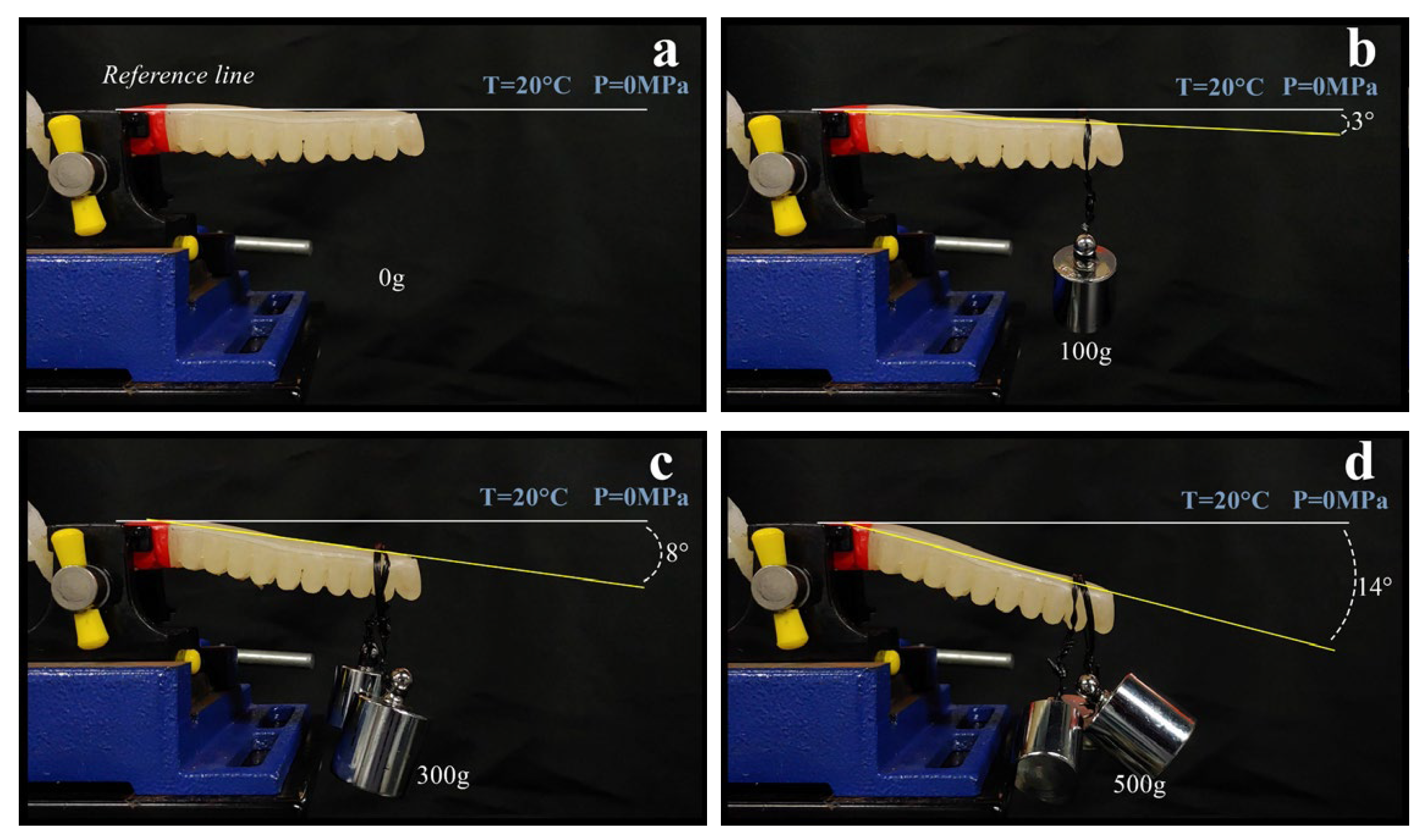
We demonstrate an average stiffness variation of ≈1150% in the actuator by varying the temperature from 50 C (33 mN/mm) to 20 C (414 mN/mm).
(4)
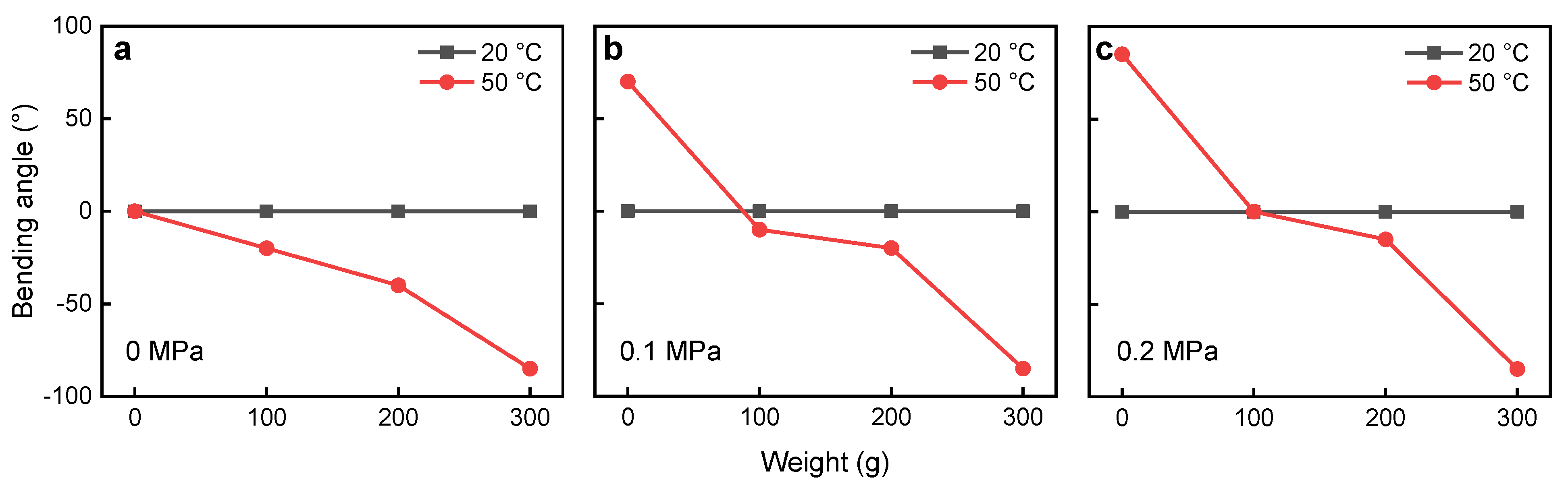
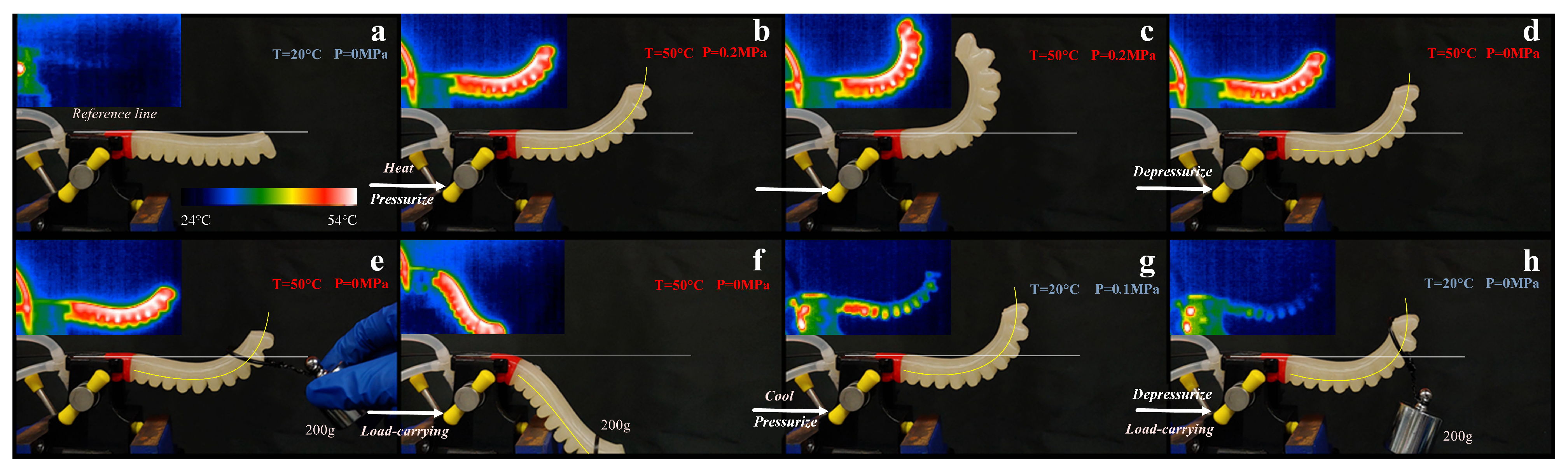
We demonstrate controllable deflection (bending) in the actuator, achieving angles between –80 and 80 by utilizing input fluid at a temperature of 20–50 C and a pressure of 0–0.2 MPa.
(5)
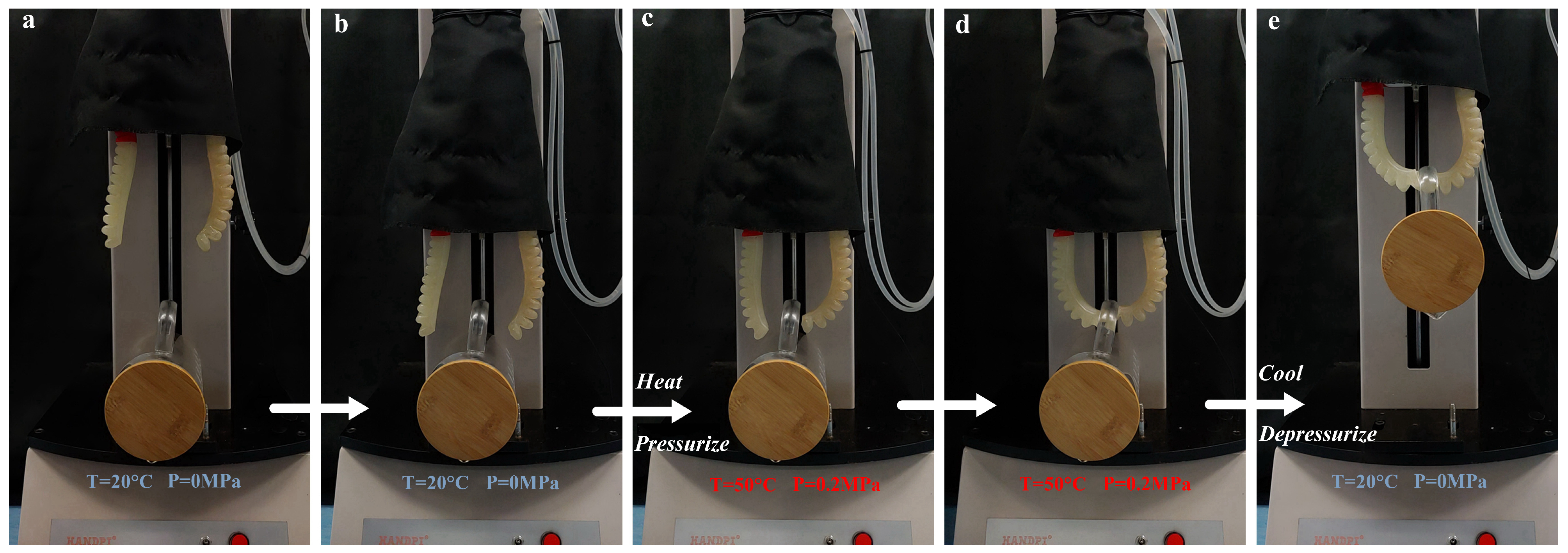
We demonstrate the gripping of objects using the actuators based on varying temperature and pressure of input hydraulics.

2. Principle

The SMPs undergo phase transition at certain temperatures resulting in variation of the stiffness of the polymers. This phenomenon can program a shape to the polymer, thereby allowing the SMP to return to its present shape during the phase transition, displaying the shape memory effect. The SMP retains this shape even after its return to the initial phase [23]. The SMP from KYORAKU CO.LTD (Japan) (SMP35, SMP45, SMP55, SMP65) possess a phase transition temperature of 35 C, 45 C, 55 C, and 65 C. These temperature-regulated characteristics of SMP can be utilized to tune the stiffness of the actuator.
The bending of a flexible tube actuator can be achieved by allowing the flow of gas through the channels of the actuator [24,25]. An increase in the tube’s gas pressure increases the actuator’s bending angle. A decrease in the tube’s gas pressure reduces the bending angle of the actuator, thereby achieving a cycle of bending actuation by regulating the gas pressure [24]. The pressure of the fluid in the tube can be controlled by the diaphragm pump as desired. In this work, we demonstrate an actuator made of SMP to achieve bending by controlling the pressure of the input fluid, and stiffness variation achieved by controlling the input fluid’s temperature.

3. Materials and Methods

3.1. Structure of the System

The control system used for controlling the variable stiffness actuator is shown in Figure 1a,b; consists of a variable stiffness soft actuator, a high-temperature fluid control system, a low-temperature fluid control system, pipelines, and switching devices. The high-temperature fluid control system and the low-temperature fluid control system are connected in parallel so that only one type of fluid (hot or cold) can flow through the actuator at any specific time. The high-temperature fluid control system consists of a high-temperature fluid buffer tank, a diaphragm pump, a valve, and pipelines connecting the three components. The high-temperature fluid buffer tank is connected to a heating device that uses a resistance heating method to heat the high-temperature fluid buffer tank. A temperature sensor is attached to monitor the temperature of the fluid. The heating device and high-temperature fluid buffer tank are connected independently from the connection between the high-temperature fluid buffer tank, the diaphragm pump, and the valve.
The low-temperature fluid control system consists of a low-temperature fluid buffer tank, a diaphragm pump, and a valve connected by pipelines. The low-temperature fluid buffer tank connected to a cooling device (thermoelectric cooler) cools the low-temperature fluid buffer tank. The cooling device and low-temperature fluid buffer tank are connected independently from the low-temperature fluid buffer tank, the diaphragm pump, and the valve.
The pipelines and switching devices include switching for one input port and two output ports, a flow valve, pipelines connecting the actuator, the high-temperature fluid control system, and the low-temperature fluid control system. The diaphragm pumps drive the high-temperature fluid, and the low-temperature fluid is of the same specifications. The direction of the flow of the low-temperature fluid and high-temperature fluid is shown with blue and red arrows, respectively, in Figure 1a,b. Since the drive system only operates in one mode at a given time (either low-temperature or high-temperature mode), a switch is used to alternate between the two modes. The pressure of the input fluid is controlled using a flow valve (Figure 1a,b). The actuator, flow valve, and switches allow the flow of both high and low-temperature fluids (red and blue lines overlap in Figure 1a,b).

3.2. Structure of the Actuator

The SMP tubular actuator has two internal channels (interconnected) that are connected to the driver system, with the two channels used for the inlet and outlet of the input fluids (Figure 2a). The liquid (hot or cold) entering the inlet port is allowed to pass throughout the actuator before reaching the outlet port, thereby improving the actuator’s heating and cooling mechanisms. The inlet and outlet ports connected to the driver system are sealed by RTV silicone sealant (Super X No. 8008, Cemedine, Shinagawa City, Tokyo, Japan). A temperature sensor is attached to the actuator to measure the temperature of the actuator during experiments. Due to the simple structure of the actuator, fully 3D printing the entire structure without any machining or assembly is possible.

3.3. Fabrication of the Actuator

The actuator is fabricated using SMP (3D Printing filament diameter = 1.75 mm) via 3D printing, and the printing parameters are shown in Table 1 [26,27]. The printing properties are selected to ensure proper sealing performance in the actuator under varying temperature and pressure. The entire structure is entirely 3D printed with no machining or assembly involved. We have selected SMP material for the fabrication process, which is non-conductive and non-magnetic, rendering MRI/CT-compatible robotics possibilities. The structure is parametrically designed and fabricated at low cost and disposable [22]. The print infill of 100% and a layer height of 0.05 mm with a first layer height of 0.2 mm is used. The print speed is maintained at 50 mm/s for excellent molding performance; the extruder and plate temperature are set to be 220 C and 0 C, respectively; the support and cooling are turned off during the 3D printing process [19]. The connections between the actuator ports and the pump are sealed using a silicone sealant to avoid leaking. The fabrication of the actuator using the 3D printing process is shown in Figure 1d and Movie S1.

4. Results

4.1. Testing of Stiffness Variation

Stiffness variation in the actuator can be achieved by regulating the temperature. The experiment is conducted by fixing the actuator at one end while the other end is free, resembling a cantilever beam. Initially, the actuator is at room temperature (20 C) with no pressure (0 MPa) and posses a straight conformation, as shown in Figure 3a and Figure 4a. When a load of 100 g is applied to the free end of the actuator (20 C, 0 MPa), it displays a negligible deflection (3 ) (Figure 4b). Increasing the load to 200 g displayed the same deflection (3 ). In comparison, an application of 300 g increased the bending to 8 (Figure 4c), and an application of 500 g further increased the bending of the actuator to 14 (Figure 4d). When a 200 g load is applied on the actuator and the temperature is raised to 50 C with no change in the pressure (0 MPa), the actuator’s stiffness is reduced. A huge deflection (19 ) is observed due to the load applied to the actuator (Figure 3c). Increasing the exposure time of this condition to the actuator will cause an increase in the bending angle (≥44 ) (Figure 3d). Decreasing the weight to 100 g and carrying out the same experiment showed a smaller bending angle (20 ), while increasing the load to 300 g showed a higher bending angle (80 ) (Figure 5). The bending angle of the actuator at different loads (0–300 g), pressures (0–0.2 MPa), and temperatures (20–50 C) of the input fluid are shown in Figure 5. Similarly, bending in the antagonistic direction can be achieved by varying the pressure and temperature to enable the actuator to maintain a shape (Figure 6).
The stiffness of the actuator at different pressures (0–0.2 MPa) and temperatures (20–50 C) is measured using the setup shown in Figure 7h. One end of the actuator is fixed, while the other free end is subjected to pressure in the downward direction to obtain the displacement of the free end of the actuator. The stiffness values of the actuator at different displacements are shown in Figure 7a. The highest stiffness in the actuator is observed at a low temperatures (20 C), with 279 mN/mm at 0 MPa, 444 mN/mm at 0.1 MPa, and 519 mN/mm at 0.2 MPa. Similarly, lower stiffness in the actuator is observed at high temperatures (50 C), with 18 mN/mm at 0 MPa, 36 mN/mm at 0.1 MPa, and 45 mN/mm at 0.2 MPa. The actuator had higher stiffness at low temperatures (20 C), as shown in Figure 7a,b. This actuator demonstrates the ability to achieve an ≈1150% increase in the average stiffness by reducing the temperature from 50 C (33 mN/mm) to 20 C (414 mN/mm). The stiffness variation of the actuator at different temperatures (20–50 C) and pressure (0–0.2 MPa) at different loads (0–300 g) is shown in Movie S2.

4.2. Factors Affecting the Actuation Mechanism

Initially, the actuator is at room temperature (≈25 C) and in a high stiffness state. Once the pressure of the flowing fluid and the actuator’s temperature is raised, the actuator reaches the low stiffness state, causing the actuator to bend, as shown in Figure 6a–h. The actuator can be restored to its initial unbent state by reducing the pressure of the fluid. Different bending angles can be achieved by different pressure values, which are controlled by the driver system. The actuator’s stiffness could be increased at any specific angle by decreasing the actuator’s temperature to 20 C, thereby achieving a high stiffness state at desired angles. The actuation and the bending process of the actuator are demonstrated in Movie S3.
The actuator’s stiffness is controlled by adjusting the temperature of the input fluid from the buffer tank, while the pressure of the fluid controls the bending. The actuator is tested at different pressures (0–0.2 MPa), and varying temperatures (50–80 C), and their corresponding bending angles are determined. The temperature of the actuator is measured using a thermometer. When the input fluid is at 50 C, the actuator reaches 40 C in 40 s at 0 MPa, 33 s at 0.1 MPa, and 29 s at 0.2 MPa (Figure 7c,d), demonstrating the influence of pressure in the heating rate of the actuator. Similarly, when the input fluid is at 65 C, the actuator reaches 40 C in 18 s at 0 MPa, 16 s at 0.1 MPa, and 16 s at 0.2 MPa, as shown in Figure 7c,d.
Similarly, when the input fluid is at 65 C, the actuator reaches 40 C in 16 s at 0 MPa, 14 s at 0.1 MPa, and 12 s at 0.2 MPa (Figure 7c,d), demonstrating that increasing the input fluid’s temperature reduces the time taken for the actuator to reach the desired temperature. When the input fluid was allowed to circulate for a longer time, the actuator reached a higher temperature with a high-temperature input fluid. Input fluid of different temperatures (50–80 C) is passed through the actuator for a specific time (39 s), and the resultant temperature of the actuator is determined (Figure 7c). When the input fluid is at 50 C, the actuator reached 40 C, 42 C, and 43 C at 0 MPa, 0.1 MPa, and 0.2 MPa respectively (Figure 7c). Similarly, when the input fluid is at 65 C, the actuator reached 50 C, 51 C, and 52 C at 0 MPa, 0.1 MPa, and 0.2 MPa respectively (Figure 7c). Similarly, when the input fluid is at 80 C, the actuator reached 56 C, 58 C, and 65 C at 0 MPa, 0.1 MPa, and 0.2 MPa, respectively (Figure 7c).
Input fluids with different temperatures (18–24 C) and pressures (0–0.2 MPa) are passed through the actuator at 52 C for 47 s and the cooling process is observed (Figure 7e,f). When input fluid was at 18 C, the actuator reached 20 C at all pressures (0–0.2 MPa), as shown in Figure 7e,f. Similarly, when the input fluid was at 24 C, the actuator reached 26 C at all pressures (0–0.2 MPa) (Figure 7e,f), demonstrating that, with a lower temperature of the input fluid, the actuator reaches the high stiffness temperature faster. The time for the actuator to reach 26 C at different temperatures (18–24 C) and pressures (0–0.2 MPa) of the input fluid is tested. When the input fluid was at 18 C, the actuator reached 26 C in 23 s, 22 s, and 21 s at 0 MPa, 0.1 MPa, and 0.2 MPa, respectively (Figure 7e,f). Similarly, when the input fluid was at 24 C, the actuator reached 26 C in 35 s, 34 s, and 28 s at 0 MPa, 0.1 MPa, and 0.2 MPa, respectively (Figure 7e,f), demonstrating that increase in pressure of the input fluid plays a role in increasing the cooling rate of the actuator.

4.3. Precision of the Actuator

The repeatability of the actuator is tested to determine the precision of the actuator. A pin is attached to the end of the actuator, and the position of the pin’s position is tracked over three actuation cycles. The background has a 1 mm × 1 mm grid. The initial position of the pin is used as a reference when the actuator is at 20 C and 0 MPa (Figure 8a). The actuator’s bending is achieved by increasing the temperature and the pressure to 50 C and 0.2 MPa. The pressure is reduced to 0 MPa to revert the actuator to its initial state, and the corresponding pin location in the grid is measured. Figure 8b shows that the pin position after one bending cycle is similar to the pin’s initial position in the grid, demonstrating full recoverability. The actuation is carried out for two more cycles, and its corresponding positions after the bending cycle are observed. Figure 8c,d displayed the pin’s position in the grid after the second bending cycle and third bending cycle, respectively. Both the positions displayed no variation in the pin’s position compared to the pin’s initial position, demonstrating high precision in the actuator’s bending.

4.4. Output Force

Bending is observed in the actuator when the pressure increases, generating an output force during the bending process. The method used to measure the output force is similar to measuring the actuator’s stiffness. The setup used for force measurement of the actuator is shown in Figure 7h. The pressure and temperature vary from 0 MPa to 0.2 MPa, and 20 C to 50 C, and the corresponding output force is measured shown in Figure 7g.
When there is no pressure (0 MPa), the actuator showed an output force of 0.17 N and 0.48 N at 20 C and 50 C, respectively (Figure 7g). An increase in pressure demonstrated an increase in the output force of the actuator. When the pressure is increased to 0.2 MPa while maintaining the temperature at 20 C, the actuator displays an output force of 0.33 N, as shown in Figure 7g. Maximum output force of 1.94 N (Table 2) is observed when the pressure and temperature is at their maximum (P = 0.2 MPa, T = 50 C).

4.5. Application

Two individual bending actuators are assembled to work antagonistically (in opposite directions) to generate a grasping action. Different temperatures and pressures of the input fluids are tested during the grasping of objects. The steps involved in the grasping of an object are shown in Figure 9a–e and Movie S4. Initially, the gripper is inactive, and the input fluid flowing through the gripper is at 20 C with no pressure (P = 0 MPa) (Figure 9a). The gripper is displaced manually towards the object (Figure 9b). The gripper is then actuated by passing an input fluid of temperature 50 C with a pressure of 0.2 MPa (Figure 9c). Once the actuators in the gripper reach 50 C, the stiffness is reduced. The actuators bend towards the object resulting in the wrapping of the object (Figure 9d). Once the object is observed to be wrapped by the gripper, the temperature and the pressure of the input fluid is reduced (T = 20 C, P = 0 MPa), followed by the lifting of the gripper with the object (Figure 9e).
The gripper can then be moved to the desired location, and the temperature of the input fluid is increased to 50 C while maintaining the pressure (P = 0 MPa). This tuning reduces the actuators’ stiffness, resulting in the gripper’s relaxation, causing the object to drop. In Figure 9a,b,e, the actuator is in high stiffness for the initial unactuated state, displacement towards the object, and during the lifting of the object. In Figure 9c,d, the actuator is in low stiffness for bending to wrap the object.

5. Discussions

Although the proposed hydraulic actuator has several advantages compared to pneumatic actuation systems, the possibilities of hydraulic fluid leakage and the use of several intricate components makes it high-maintenance, which could drive up the operation cost for some applications. Further investigations will be carried out to reduce the number of components to improve the usability of this device. Although the developed gripper is able to demonstrate pick and place applications using the temperature and pressure variations in the input fluid, the time required to complete the process is ≥20 s, which could limit its use in carrying out complex high-speed tasks. This slow actuation is due to the heat transfer between the input fluid and the polymer, which will be further investigated in the future. In addition, most of the biomedical applications involving navigation or surveillance can be achieved with less than 180° bending angles. Since we are fabricating the device with a vision of using it in biomedical applications, the demonstrated values of hydraulic pressure will be sufficient to achieve these applications. However, increasing the pressure further could damage the channels especially when actuated for multiple cycles at higher frequencies. Currently, the actuator will be able to perform 10–50 bending cycles at the demonstrated pressure and temperature range with minor performance losses. We envision further investigating and improving in the future.

6. Conclusions

In summary, we present a variable stiffness actuator fabricated using SMP via a one-step 3D printing process without any machining or assembly. The actuator demonstrates its ability to vary stiffness and to bend based on the input fluid from the fluid-controlled system. The actuator demonstrates a stiffness variation from 18 mN/mm to 519 mN/mm by varying the input fluid’s temperature from 50 C to 20 C and varying the pressure of the input fluid from 0 MPa to 0.2 MPa. We also demonstrate ≈1150% increase in the average stiffness by reducing the temperature from 50 C (33 mN/mm) to 20 C (414 mN/mm). The actuator also demonstrates a 160 bending angle (–80 to 80 ) by varying the temperature (20–50 C) and pressure (0–0.2 MPa) of the input fluid. The actuator was able to switch from a low to high-stiffness state in 12 s (20 C to 50 C) when the input fluid is at 80 C and 0.2 MPa; it was also able to switch from a high to low-stiffness state in 21 s by varying its input pressure and temperature. The actuator also displayed variation in the output force from 0.17 N to 1.94 N by varying the temperature (20–50 C) and pressure (0–0.2 MPa) of the input fluid. We also demonstrate a grasping device using two individual actuators operating antagonistically to grasp an object (≈100 g). This integrated stiffness–actuation control enables rapid switching between stiffness, suitable for applications such as soft precision gripping and biomedical human-interactive manipulators. Due to the non-magnetic and non-conductive nature of the actuator material (SMP), its use could extend to MRI/CT compatible robots. The actuator’s low-cost fabrication and disposable nature make endoscopic applications feasible after the high-temperature from the actuator and biocompatible issues are solved.

Supplementary Materials

The following are available online at https://drive.google.com/file/d/1Tva76z9vvukKFICKupeTdnLKfG5vvfTJ/view?usp=sharing, Movie S1: Demonstration of the 3D printing process involved in the fabrication of the actuator, Movie S2: Demonstration of the stiffness variation of the actuator, Movie S3: Demonstration of the shape setting of the actuator, Movie S4: Demonstration of actuation and bending of the actuator, Movie S5: Demonstration of object gripping.

Author Contributions

Conceptualization, H.R.; methodology, H.R. and T.L.; validation, T.L. and H.R.; investigation, T.L.; resources, H.R.; data curation, H.R., M.S.K. and T.L.; writing–original draft preparation, M.S.K., T.L. and H.R.; writing–review and editing, M.S.K., C.J.C., Z.T.H.T. and H.R.; visualization, M.S.K., T.L. and H.R.; supervision, H.R.; project administration, H.R.; funding acquisition, H.R. All authors have read and agreed to the published version of the manuscript.

Funding

This work was supported by the Shun Hing Institute of Advanced Engineering (SHIAE project BME-p1-21, 8115064) at the Chinese University of Hong Kong (CUHK), CUHK Direct Grant for Research 4055139, and the Singapore Academic Research Fund under Grant R-397-000-353-114.

Institutional Review Board Statement

Not applicable.

Informed Consent Statement

Not applicable.

Data Availability Statement

Not applicable.

Conflicts of Interest

The authors declare no conflict of interest.

References

  1. Li, L.; Godaba, H.; Ren, H.; Zhu, J. Bioinspired Soft Actuators for Eyeball Motions in Humanoid Robots. IEEE/ASME Trans. Mechatron. 2019, 24, 100–108. [Google Scholar] [CrossRef]
  2. Li, C.; Gu, X.; Xiao, X.; Lim, C.M.; Ren, H. A Robotic System With Multichannel Flexible Parallel Manipulators for Single Port Access Surgery. IEEE Trans. Ind. Inform. 2019, 15, 1678–1687. [Google Scholar] [CrossRef]
  3. Yufei, H.; Tianmiao, W.; Xi, F.; Kang, Y.; Ling, M.; Juan, G.; Li, W. A variable stiffness soft robotic gripper with low-melting-point alloy. In Proceedings of the 2017 36th Chinese Control Conference (CCC), Dalian, China, 26–28 July 2017; pp. 6781–6786. [Google Scholar] [CrossRef]
  4. Hong, S.W.; Yoon, J.Y.; Kim, S.H.; Lee, S.K.; Kim, Y.R.; Park, Y.J.; Kim, G.W.; Choi, S.B. 3D-Printed Soft Structure of Polyurethane and Magnetorheological Fluid: A Proof-of-Concept Investigation of its Stiffness Tunability. Micromachines 2019, 10, 655. [Google Scholar]
  5. Banerjee, H.; Li, T.; Ponraj, G.; Senthil Kumar, K.; Lim, C.M.; Ren, H. Origami-Layer-Jamming Deployable Retractor with Variable Stiffness and Tactile Sensing. J. Mech. Robot. 2019. [Google Scholar] [CrossRef]
  6. Abeach, L.A.A.; Nefti-Meziani, S.; Theodoridis, T.; Davis, S. A Variable Stiffness Soft Gripper Using Granular Jamming and Biologically Inspired Pneumatic Muscles. J. Bionic Eng. 2018, 15, 236–246. [Google Scholar]
  7. Li, C.; Gu, X.; Xiao, X.; Lim, C.M.; Ren, H. Flexible Robot with Variable Stiffness in Transoral Surgery. IEEE/ASME Trans. Mechatron. 2019, 25, 1–10. [Google Scholar] [CrossRef]
  8. Kalairaj, M.S.; Yeow, B.S.; Lim, C.M.; Ren, H. Needle-Size Bending Actuators Based on Controlled Nitinol Curvatures and Elastic Structures. J. Mech. Robot. 2020, 12, 031015. [Google Scholar] [CrossRef]
  9. Taylor, A.J.; Slutzky, T.; Feuerman, L.; Ren, H.; Tokuda, J.; Nilsson, K.; Tse, Z.T.H. MR-Conditional SMA-Based Origami Joint. IEEE/ASME Trans. Mechatron. 2019, 24, 883–888. [Google Scholar] [CrossRef]
  10. Kang, B.; Kojcev, R.; Sinibaldi, E. The first interlaced continuum robot, devised to intrinsically follow the leader. PLoS ONE 2016, 11, e0150278. [Google Scholar]
  11. Zhang, J.; Wang, T.; Hong, J.; Wang, Y. Review of Soft-bodied Manipulator. J. Mech. Eng. 2017, 53, 19–28. [Google Scholar]
  12. Li, J.; Sun, M.; Wu, Z.; Yin, H. Design, Analysis, and Grasping Experiments of a Novel Soft Hand: Hybrid Actuator Using Shape Memory Alloy Actuators, Motors, and Electromagnets. Soft Robot. 2018, 7, 396–407. [Google Scholar] [CrossRef]
  13. Farimani, F.S.; Mojarradi, M.; Hekman, E.; Misra, S. PneuAct-II: Hybrid Manufactured Electromagnetically Stealth Pneumatic Stepper Actuator. IEEE Robot. Autom. Lett. 2020, 5, 3588–3593. [Google Scholar]
  14. Zhang, Y.F.; Zhang, N.; Hingorani, H.; Ding, N.; Wang, D.; Yuan, C.; Zhang, B.; Gu, G.; Ge, Q. Fast-Response, Stiffness-Tunable Soft Actuator by Hybrid Multimaterial 3D Printing. Adv. Funct. Mater. 2019, 29, 1806698. [Google Scholar] [CrossRef]
  15. Santo, L.; Quadrini, F.; Bellisario, D.; Iorio, L. Applications of Shape-Memory Polymers, and Their Blends and Composites. In Shape Memory Polymers, Blends and Composites: Advances and Applications; Parameswaranpillai, J., Siengchin, S., George, J.J., Jose, S., Eds.; Springer: Singapore, 2020; pp. 311–329. [Google Scholar] [CrossRef]
  16. Haskew, M.J.; Hardy, J.G. A mini-review of shape-memory polymer-based materials. Johns. Matthey Technol. Rev. 2020, 64, 425–442. [Google Scholar]
  17. Akbari, S.; Sakhaei, A.H.; Panjwani, S.; Kowsari, K.; Serjouei, A.; Ge, Q. Multimaterial 3D printed soft actuators powered by shape memory alloy wires. Sens. Actuators A Phys. 2019, 290, 177–189. [Google Scholar]
  18. Kang, M.; Pyo, Y.; Young Jang, J.; Park, Y.; Son, Y.H.; Choi, M.; wan Ha, J.; Chang, Y.W.; Lee, C.S. Design of a shape memory composite (SMC) using 4D printing technology. Sens. Actuators A Phys. 2018, 283, 187–195. [Google Scholar]
  19. Yang, Y.; Chen, Y.; Wei, Y.; Li, Y. 3D printing of shape memory polymer for functional part fabrication. Int. J. Adv. Manuf. Technol. 2016, 84, 2079–2095. [Google Scholar] [CrossRef]
  20. Zolfagharian, A.; Kouzani, A.Z.; Khoo, S.Y.; Moghadam, A.A.A.; Gibson, I.; Kaynak, A. Evolution of 3D printed soft actuators. Sens. Actuators A Phys. 2016, 250, 258–272. [Google Scholar]
  21. Gul, J.Z.; Sajid, M.; Rehman, M.M.; Siddiqui, G.U.; Shah, I.; Kim, K.H.; Lee, J.W.; Choi, K.H. 3D printing for soft robotics—A review. Sci. Technol. Adv. Mater. 2018, 19, 243–262. [Google Scholar]
  22. MacCurdy, R.; Katzschmann, R.; Kim, Y.; Rus, D. Printable hydraulics: A method for fabricating robots by 3D co-printing solids and liquids. In Proceedings of the 2016 IEEE International Conference on Robotics and Automation (ICRA), Stockholm, Sweden, 16–21 May 2016; pp. 3878–3885. [Google Scholar]
  23. Huang, W.M.; Yang, B.; An, L.; Li, C.; Chan, Y.S. Water-driven programmable polyurethane shape memory polymer: Demonstration and mechanism. Appl. Phys. Lett. 2005, 86, 114105. [Google Scholar] [CrossRef]
  24. Mosadegh, B.; Polygerinos, P.; Keplinger, C.; Wennstedt, S.; Shepherd, R.F.; Gupta, U.; Shim, J.; Bertoldi, K.; Walsh, C.J.; Whitesides, G.M. Pneumatic Networks for Soft Robotics that Actuate Rapidly. Adv. Funct. Mater. 2014, 24, 2163–2170. [Google Scholar] [CrossRef]
  25. Polygerinos, P.; Lyne, S.; Wang, Z.; Nicolini, L.F.; Mosadegh, B.; Whitesides, G.M.; Walsh, C.J. Towards a Soft Pneumatic Glove for Hand Rehabilitation. In Proceedings of the 2013 IEEE/RSJ International Conference on Intelligent Robots and Systems, Tokyo, Japan, 3–7 November 2013; pp. 1512–1517. [Google Scholar] [CrossRef]
  26. Salimon, A.; Senatov, F.; Kalyaev, V.; Korsunsky, A. Chapter 6—Shape memory polymer blends and composites for 3D and 4D printing applications. In 3D and 4D Printing of Polymer Nanocomposite Materials; Sadasivuni, K.K., Deshmukh, K., Almaadeed, M.A., Eds.; Elsevier: Amsterdam, The Netherlands, 2020; pp. 161–189. [Google Scholar] [CrossRef]
  27. Yang, Y.; Chen, Y. Novel design and 3D printing of variable stiffness robotic fingers based on shape memory polymer. In Proceedings of the 2016 6th IEEE International Conference on Biomedical Robotics and Biomechatronics (BioRob), Singapore, 26–29 June 2016; pp. 195–200. [Google Scholar] [CrossRef]
Figure 1. Control of the SMP-based variable stiffness actuator. (a) Schematic showing the setup used for controlling the stiffness variation and bending of the actuator. The driver system consists of a high-temperature fluid buffer tank, a heating device, a low-temperature fluid buffer tank, a cooling device, two diaphragm pumps, two valves, a flow valve, a switch. The blue arrow represents the flow direction of the low-temperature fluid, and the red arrow represents the flow direction of the high-temperature fluid. (b) An optical photo showing the setup of the driving system used for controlling the actuator. The blue arrow represents the flow direction of the low-temperature fluid, and the red arrow represents the flow direction of the high-temperature fluid. (c) Infrared thermographic images of the actuator during the heating (actuation) and cooling (relaxation) process. (d) An optical photo showing the 3D printing process during the fabrication of the actuator. The layer height is set as thin as 0.05 mm, and the print infill is 100%. The fabrication process (3D printing) of the actuator is shown in Movie S1.
Actuators 10 00269 g001
Figure 2. The design and working of the actuator. (a) Cross-section of the actuator showing the channel for the input fluid. (b) An optical photo of the 3D printed actuator showing its structure with inlet and outlet channel. (c) The actuator’s schematic shows the channels’ design, the connection between the two channels to facilitate fluid flow. (d) An optical photo showing the side view of the 3D printed actuator. (e) The axial section of the actuator showing the detailed structure of the channels and connectors. (f) An optical photo showing the top view of the 3D printed actuator. (g) Schematic showing the bending of the actuator. (h) An optical photo showing the side view of the bending actuator with arrows representing the input fluid flow.
Actuators 10 00269 g002
Figure 3. Demonstration of stiffness variation in the actuator at different conditions. (a) Initial state (T = 20 C, P = 0 MPa) of the actuator with no load. The white line denotes reference. (b) Bending of the actuator when a load of 200 g is suspended to the actuator at 20 C and 0 MPa. The yellow line represents the bending profile of the actuator. (c) Bending of the actuator when temperature increased to 50 C while maintaining its pressure (0 MPa) and load (200 g). (d) Bending of the actuator during prolonged loading (200 g) at 50 C and 0 MPa. The stiffness variation of the actuator at different temperature and pressure is shown in the Movie S2.
Actuators 10 00269 g003
Figure 4. Demonstration of the load-bearing capability of the actuator at 20 C and 0 MPa. (a) The actuator is in its initial state with no weight suspended. The white line denotes reference. (b) Bending of the actuator when 100 g weight is suspended. The yellow line represents the bending profile of the actuator. (c) Bending of the actuator when 300 g weight is suspended. (d) Bending of the actuator when 500 g weight is suspended. The stiffness variation of the actuator at different temperatures and pressures is shown in Movie S2.
Actuators 10 00269 g004
Figure 5. Bending performance of the actuator at different weights (0–300 g) at different temperature (20–50 C) when the pressure of input fluid is (a) 0 MPa, (b) 0.1 MPa, (c) 0.2 MPa.
Actuators 10 00269 g005
Figure 6. The demonstration of actuation and bending of the actuator. (a) Initial state of the actuator (T = 20 C, P = 0 MPa). (b) The actuator’s pressure and temperature increased (T = 50 C, P = 0.2 MPa) to achieve bending. The white line denotes the reference, and the yellow line represents the bending profile of the actuator. (c) The actuation time is increased to achieve a higher bending angle. (d) The actuator’s pressure is decreased while maintaining the temperature (T = 50 C, P = 0 MPa) to revert the actuator to its initial position. (e) Demonstration of loading (200 g) in the actuator (T = 50 C, P = 0 MPa). (f) Demonstration of bending in the opposite direction due to the high load suspended in the actuator. (g) High-stiffness state of the actuator is achieved by unloading the actuator and reducing its input temperature and pressure (T = 20 C, P = 0.1 MPa) to achieve a high-stiffness state in the actuator. (h) Demonstration of the load-carrying capacity (200 g) of the actuator when the pressure is reduced (T = 20 C, P = 0 MPa). The thermography images of (ah) is shown in the inset of (ah) respectively. The actuation and the bending process of the actuator is shown in Movie S3.
Actuators 10 00269 g006
Figure 7. Testing the stiffness variations, temperature variations, and output force of the actuator. (a) Output force of the actuator during displacement at different temperature (20–50 C) and pressure (0–0.2 MPa) of the input fluid. (b) Stiffness variation of the actuator at different temperature (20–50 C) and pressure (0–0.2 MPa) of the input fluid. (c) Dynamic change in the temperature of the actuator at different temperature (50–80 C) and pressure (0–0.2 MPa) of the input fluid. (d) Time required by the actuator to reach 50 C at different temperatures (50–80 C) and pressures (0–0.2 MPa) of the input fluid. (e) Dynamic change in the temperature of the actuator at different temperatures (18–24 C) and pressures (0–0.2 MPa) of the input fluid. (f) Time required by the actuator to reach 20 C at different temperatures (18–24 C) and pressures (0–0.2 MPa) of the input fluid. (g) Output force of the actuator at different temperatures (20–50 C) and pressures (0–0.2 MPa) of the input fluid. (h) An optical photo showing the set-up utilized to perform the stiffness test of the actuator.
Actuators 10 00269 g007
Figure 8. Testing the precision positioning of the actuator. A pin attached to the end of the actuator to indicate its position against the background of a 1 mm × 1 mm grid. (a) Initial position. (b) Position after the first bending cycle. (c) Position after second bending. (d) Position after third bending cycle.
Actuators 10 00269 g008
Figure 9. The demonstration of object gripping. (a) The gripper comprised of two actuators at initial state (T = 20 C, P = 0 MPa). (b) Gripper displaced to approach the object. (c) Pressure and temperature of the input fluid are increased (T = 50 C, P = 0.2 MPa) to facilitate the bending of the gripper. (d) The bending of the gripper is utilized for grasping the object firmly. (e) The input fluid’s temperature and pressure are reduced to 20 C, and 0 MPa and the object is lifted off the surface. The grasping of the object (≈100 g) using the gripper is shown in Movie S4.
Actuators 10 00269 g009
Table 1. Tabulation of printing parameters.
Printing ParameterValue
Layer Height (mm)0.05
First Layer Height (mm)0.2
Print Speed (mm/s)50
Extruder Temperature ( C)220
Plate Temperature ( C)0
Print Infill100%
SupportNo
CoolingNo
Table 2. The table of average ratio.
PropertiesAverage Ratio
Stiffness
(T = 20 C: T = 50 C)
13.1:1
Heating Time
(T = 50 C: T = 65 C: T = 80 C)
2.4:1.2:1
Cooling Time
(T = 24 C: T = 18 C)
1.5:1
The Maximum Output Force
(T = 50 C: T = 20 C)
5.9:1
Publisher’s Note: MDPI stays neutral with regard to jurisdictional claims in published maps and institutional affiliations.

