Article

On the Static Pull-In of Tilting Actuation in Electromagnetically Levitating Hybrid Micro-Actuator: Theory and Experiment

by
Kirill Poletkin
1,2
1
Institute of Microstructure Technology—Karlsruhe Institute of Technology, Hermann-von-Helmholtz-Platz 1, 76344 Eggenstein-Leopoldshafen, Germany
2
Institute of Robotics and Computer Vision, Innopolis University, 1 Universitetskaya Street, 420500 Innopolis City, Russia
Actuators 2021, 10(10), 256; https://doi.org/10.3390/act10100256
Submission received: 29 July 2021 / Revised: 12 September 2021 / Accepted: 24 September 2021 / Published: 29 September 2021
(This article belongs to the Special Issue Cooperative Microactuator Systems)

Abstract

:
This work presents the results of the experimental and theoretical study of the static pull-in of tilting actuation executed by a hybrid levitation micro-actuator (HLMA) based on the combination of inductive levitation and electrostatic actuation. A semi-analytical model to study such a pull-in phenomenon is developed, for the first time, as a result of using the qualitative technique based on the Lagrangian approach to analyze inductive contactless suspensions and a recent progress in the calculation of mutual inductance and force between two circular filaments. The obtained non-linear model, accounting for two degrees of freedom of the actuator, allows us to predict accurately the static pull-in displacement and voltage. The results of modeling were verified experimentally and agree well with measurements.

1. Introduction

Electromagnetic levitation micro-actuators employing remote ponderomotive forces, in order to act on a target environment or simply compensate a gravity force for holding stably a micro-object at the equilibrium without mechanical attachment, have already found wide applications and demonstrated a new generation of micro-sensors and -actuators with increased operational capabilities and overcoming the domination of friction over inertial forces at the micro-scale.
There are number of techniques, which provide the implementation of electromagnetic levitation into a micro-actuator system and can be classified according to the materials used and the sources of the force fields in two major branches: electric levitation micro-actuators (ELMA) and magnetic levitation micro-actuators (MLMA). In particular, ELMA were successfully used as linear transporters [1] and in micro-inertial sensors [2,3]. MLAM can be further split into inductive (ILMA), diamagnetic (DLMA), superconducting micro-actuators and hybrid levitation micro-actuators (HLMA) [4], which have found applications in microbearings [5,6,7], micromirrors [8,9], micro-gyroscopes [10,11], micro-accelerometers [12], bistable switches [13], nanoforce sensors [14], microtransporters [15], microaccelerators [16], micromotors [17,18,19] and resonators [20].
A wide spectrum of physical principles have been utilized and successfully implemented by using different techniques for microfabrication. However, recently developed 3D microcoil technology [21] together with the integration of a polymer magnetic composite material for flux concentration, allows announcing inductive levitation micro-actuator systems—firstly, as systems with established micro-fabrication process in comparison to the other levitation actuator systems and, secondly, as high-performance systems. As a result of this progress, our group demonstrated the inductive levitation actuator system with the record lowest current consumption [7] around tens of mA. This permits us to avoid using standard bulky high-frequency current amplifiers for exciting the ILMA and to replace them with the integrated control circuit including the signal generator and amplifier and with a size comparable to the size of the micro-actuator system [22].
HLMAs, in which, for instance, the inductive levitation micro-actuator system can be joined with a source of electrostatic field, dramatically increase the capabilities of levitated micro-systems [4] and demonstrate a wide range of different operation modes such as the linear and angular positioning, bi-stable linear and angular actuation and the adjustment of stiffness components, as it was reported in [17,23] and presented by the author at Transducers 2017 [24]. These capabilities open a new very promising perspective to create smart micro-actuator systems with new functional abilities implemented, for instance, by means of the coherent cooperation of distributed microactuators, multistable actuation, mechanical and electromagnetic couplings.
Although the linear pull-in actuation has been comprehensively studied theoretically as well as experimentally [25], the angular pull-in phenomenon of tilting actuation in such HLMAs has not yet been addressed. In this article, in order to fill this gap, a prototype of hybrid levitation micro-actuator was fabricated to experimentally demonstrate and characterize the static pull-in behavior of tilting actuation. Using the qualitative technique based on the Lagrangian approach [26], a semi-analytical model for mimicking such the static pull-in behavior based on two circuit approximation of induced eddy current with proof mass is developed. Upon tilting the levitated disc, the geometrical transformation of eddy current circuit is analyzed by means of finite element approach proposed in [27]. As a result of this analysis was developed a semi-analytical function for calculation mutual inductance and corresponding electromagnetic force and torque by Kalantarov–Zeitlin’s method [28]. Thus, the particularity of the developed model is to employ this new derived function for calculation of mutual inductance and to account for two degrees of freedom, namely, linear displacement in the vertical direction and angular displacement of the levitated disc. Through this study we verified successfully the given assumptions for modelling and developed the robust analytical tool to describe the static pull-in actuation of HLMAs.

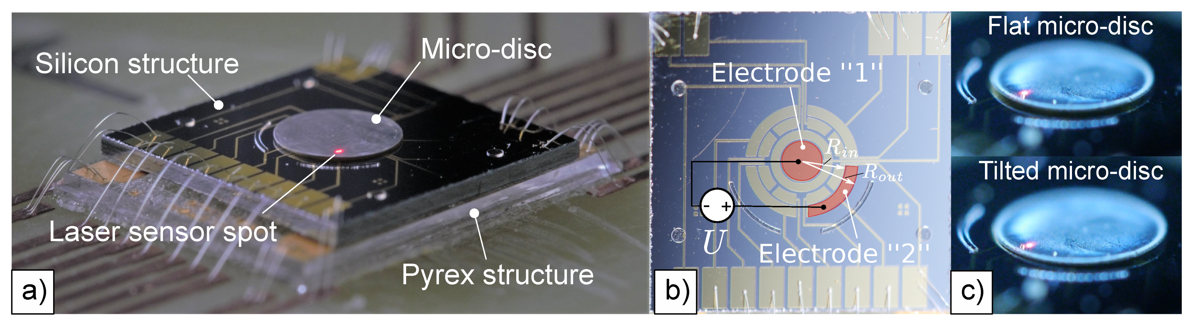
2. Fabrication and Measurements

In order to comprehensively study the static pull-in of tilting actuation executed by the HLMA, we fabricated a microprototype, as shown in Figure 1a, by using a similar fabrication process as the one reported in work [17]. Namely, the hybrid actuator consists of two structures fabricated independently, namely, the Pyrex structure and the silicon structure, which were aligned and assembled by flip-chip bonding into one device with the dimensions: 9.4 mm × 7.4 mm × 1.1 mm, as shown in Figure 1a.
The Pyrex structure includes two coaxial 3D wire-bonded microcoils similar to those reported in our previous work [6], namely, the stabilization and the levitation coils, fabricated on Pyrex substrate using SU-8 2150. The function of this structure is to stably levitate an aluminum disc-shaped proof mass (PM). For this particular device, the height of the coils is 500 μ m and the number of windings is 20 and 12 for levitation and stabilization coils, respectively. This coil structure is able to levitate PMs with diameters ranging from 2.7 to 3.3 m m [6].
The silicon structure was fabricated on a SOI wafer with a device layer of 40 μ m , the buried oxide of 2 μ m , a handle layer of 600 μ m and the resistivity of silicon in a range of 1.30 Ω c m , as it was reported in work [29]. Additionally, the device layer has a 500 nm oxide layer for passivation, on top of which electrodes are patterned by UV lithography on evaporated Cr/Au layers (20/150 nm). The fabricated electrode set, which is hidden by the levitated micro-disc in Figure 1a, is shown in Figure 1b. After etching the handle layer up to the buried oxide by DRIE, the silicon structure was aligned and bonded onto the Pyrex structure. Note that the internal structure of the fabricated device is similar to one shown and discussed in our works [17,29]. Finally, the fabricated device was glued and wire-bonded on a PCB board as shown in Figure 1a.
The actuator coils were fed by AC current at the frequency of 10 MHz, with an RMS value ranging from 100 mA to 130 mA. This range of changing of AC current allowed us to levitate a disc with a diameter of 2.8 m m within a height from 35 to 190 μ m measured from the surface of the electrodes patterned on the silicon substrate. Pull-in of tilting actuation was performed by applying pull-in voltage to electrodes “1” and “2”, as shown in Figure 1b,c. The circular electrode “1” has a diameter of 1 m m corresponding to an area A 1 of around ∼0.8 m m 2 . Whereas, the geometry of the sectorial electrode “2” is characterized by the following parameters: an inner radius R i n of 1.1 m m , an outer radius R o u t of 1.4 m m and the center angle of π / 2 rad , which corresponds to an area A 2 of around ∼0.43 m m 2 . The electrode set was able to generate the tilting torque within a range of 0.7 × 10 10   N m . The linear displacement of a disc edge was measured by a laser distance sensor (LK-G32) directly (see Figure 1a,c). The measurements were performed at two levitation heights. Namely, the disc was levitated at 130 and 150 μ m . The measured results at these two heights are referred to further in the article as measurement I and II, respectively. The pull-in actuation occurred for the applied voltages of 27 and 33 V and the measured pull-in displacements were 34 and 45 μ m , respectively. The results of measurements accompanying the results of modeling are summarized in Table 1 below.

3. Simulation and Modeling

The mechanism of stable levitation of the disc-shaped proof mass in the framework of two coil design is as follows. The induced eddy currents are distributed along the levitated proof mass in such a way that two circuits with maximum values of eddy current density can be identified. The first circuit corresponds to the eddy current distributed along the edge of disc-shaped PM and the second circuit is defined by the levitation coil. The latter one has a circular path with radius equal to the radius of the levitation coil. Hence, this mechanism can be split into two force interactions. The force interaction occurs between the current in the stabilization coil and induced eddy current corresponding to the first circuit, which contributes mainly to the lateral stability of the levitated PM. Whereas, the force interaction between the current in the levitation coil and induced eddy current related to the second circuit contributes mainly to the vertical and angular stability of the levitated PM [26].
Upon tilting the PM, the eddy current circuit generated by the levitation coil is transformed form a circular shape into an elliptical one. In the section below, this transformation of the shape of eddy current circuit is analyzed by quasi-finite element approach recently developed in [27,30,31]. As a result of the analysis, formulas for calculation of the mutual inductance and corresponding electromagnetic torque and force acting on the PM are derived by employing Kalantarov–Zeitlin’s method [28]. Then the derived formulas are applied to the modeling of the pull-in actuation in the HLMA.

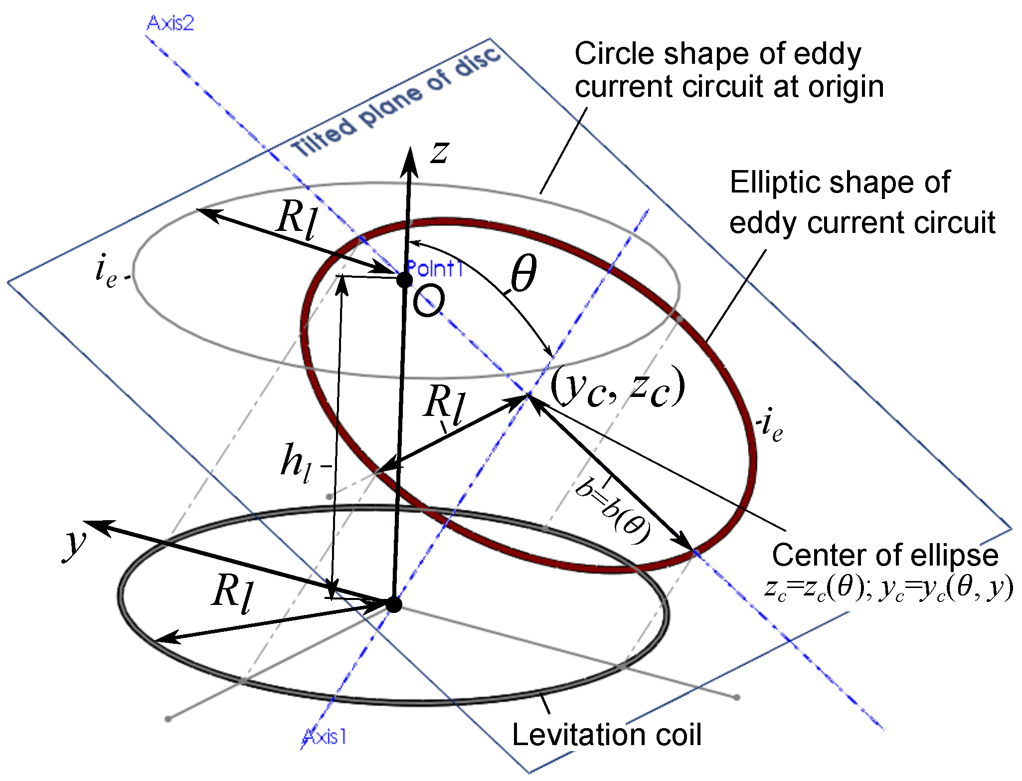
3.1. Simulation of Induced Eddy Current within the Tilting Proof Mass

According to the procedure proposed in our previous work [27], the disc is meshed by circular elements, as shown in Figure 2a. For the particular case, the levitated micro-disc is meshed by circular elements, each of them having the same radius of R e =   2.4814 × 10 5   m . For the disc with a diameter of 2.8 m m , a number of elements is n = 2496 . 3D scheme of two micro-coils is approximated by a series of circular filaments. The levitation coil is replaced by 20 circular filaments with a diameter of 2.0   m m , while the stabilization coil—by 12 circular filaments with a diameter of 3.8   m m . Thus, the total number of circular filaments, N, is 32. Assigning the origin of the fixed frame { X k } ( k = 1 , 2 , 3 ) to the centre of the circular filament corresponding to the first top winding of the levitation coil, the linear position of the circular filaments of levitation coil can be defined as ( j ) r c = [ 0 0 ( j 1 ) · p ] T , ( j = 1 , , 20 ) , where p is the pitch equaling to 25 μ m . The same is applicable for stabilization coil, ( j ) r c = [ 0 0 ( j 21 ) · p ] T , with the difference that the index j varies from 21 to 32. For both coils, the Bryan angle of each circular filament is ( j ) ϕ ̲ c = [ 0 0 0 ] T , ( j = 1 , , 32 ) . Note that all notations and introduced math variables used in the main text are listed in the nomenclature shown in Appendix A.
The result of meshing becomes a list of elements { ( s ) C ̲ = [ ( s ) ρ ( s ) ϕ ] T } ( s = 1 , , n ) containing information about a radius vector and an angular orientation for each element with respect to the coordinate frame { x k } ( k = 1 , 2 , 3 ). Now a matrix L ̲ of self-inductances of circular elements and mutual inductances between them can be formed as follows
L ̲ = L o E ̲ + M ̲ o ,
where E ̲ is the ( 2496 × 2496 ) unit matrix, M ̲ o is the ( 2496 × 2496 ) — symmetric hollow matrix whose elements are L k s o ( k s ). The self-inductance of the circular element is calculated by the known formula for a circular ring of circular cross-section
L o = μ 0 R e ln 8 / ε t 7 / 4 + ε t 2 / 8 ln 8 / ε t + 1 / 3 ,
where μ 0 is the magnetic permeability of free space, ε t = t h / ( 2 R e ) , t h is the thickness of a meshed layer of micro-object (in the particular case, t h = 13 μ m ).
Accounting for the values of diameters of levitation and stabilization coils, 3D geometrical scheme of the actuator for the eddy current simulation can be build as shown in Figure 2b. The position of the coordinate frame { x k } ( k = 1 , 2 , 3 ) with respect to the fixed frame { X k } ( k = 1 , 2 , 3 ) is defined by the radius vector r c m = [ 0 0 h l ] T , where the levitation height, h l is to be 100 μ m . Then, the position of the s-mesh element with respect to the coordinate frame { ( j ) z k } ( k = 1 , 2 , 3 ) assigned to the j-coil filament can be found as ( s , j ) r = r c m + ( s ) ρ ( j ) r c or in matrix form as
( s , j ) r ̲ z = ( j ) A ̲ z X r ̲ c m X + ( j ) A ̲ z x ( s ) ρ ̲ x ( j ) A ̲ z X ( j ) r ̲ c X ,
where ( j ) A ̲ z X = ( j ) A ̲ z X ( j ) ϕ ̲ c = ( j ) e ̲ z · e ̲ X and ( j ) A ̲ z x = ( j ) A ̲ z X ( j ) ϕ ̲ c A ̲ X x ( φ ̲ ) = ( j ) e ̲ z · e ̲ x are the direction cosine matrices, φ ̲ = [ θ 0 0 ] is the vector of the angular generalized coordinates.
All matrices of ( j ) ϕ ̲ c are zeros. Hence, ( j ) A ̲ z X = E ̲ , where E ̲ is the ( 3 × 3 ) unit matrix and ( j ) A ̲ z x = ( j ) A ̲ z X ( j ) ϕ ̲ c A ̲ X x ( φ ̲ ) = E ̲ A ̲ X x ( φ ̲ ) = A ̲ X x ( φ ̲ ) . As an illustrative example, the angle θ is chosen to be 12 , as shown in Figure 2b. Moreover, the coils are represented by the circular filaments and using the radius vector ( s , j ) r , the mutual inductance between the j- coil and s-meshed element can be calculated directly using the formula presented in [28]. Thereby, the ( 2496 × 32 ) matrix M ̲ c of mutual inductance between coils and finite elements can be formed. The induced eddy current in each circular element is a solution of the following matrix equation
I ̲ = L ̲ 1 M ̲ c I ̲ c ,
where I ̲ is the ( 2496 × 1 ) matrix of eddy currents and I ̲ c = [ I c 1 I c 2 I c N ] T is the given ( 32 × 1 ) matrix of currents in coils.
For calculation, dimensionless currents in the levitation coil and stabilization one are introduced by dividing currents on the amplitude of the current in the levitation coil. Note that the amplitude of the current in both coils are the same. Hence, the input current in the levitation coil filaments is to be one, while in the stabilization coil filaments it is minus one (because of the 180° phase shift). Now, the induced eddy current in dimensionless values can be calculated [27]. The result of calculation is shown in Figure 2c as a 3D plot. The intensity of the color shown by the bar characterizes the value of dimensionless magnitude of the eddy current. Figure 2d shows a 2D plot of the distribution of magnitudes of eddy current along the area of the surface of the PM. As it is seen from Figure 2c,d, the maximum of eddy current magnitudes are distributed along the edge of the PM and around its centre. Moreover, the analysis of Figure 2d depicts that a circular shape of maximum magnitude of eddy current induced by the current of the stabilization coil without tilting the PM [27] is transformed into an elliptical shape with shifting its center, as shown in Figure 2d. The center of the ellipse is defined by the following coordinates z c = z c ( θ ) and y c = y c ( θ ) , which are also functions of the tilting angle θ .

3.2. Mutual Inductance between Two Filaments of Circular and Elliptic Shapes

Approximating the elliptical shape of distribution of the eddy current magnitude around the centre of the PM by a filament, a function for calculation of the mutual inductance between the elliptical filament with the shifted center and circular filament is derived by using Kalantarov–Zeitlin’s method. A scheme with detailed particularities of geometry for calculation is shown in Figure 3.
Accounting for Figure 3 and introducing the following dimensionless coordinates,
z = z c R l ; y = z tan ( θ ) tan 2 ( θ ) + 1 ,
the formula for calculation of the mutual inductance can be written as
M = μ 0 R l π 0 2 π r · F · Φ ( k ) d φ ,
where
r = r ( θ ) = cos θ ( tan 2 ( θ ) + 1 ) sin 2 ( φ ) + cos 2 ( θ ) cos 2 ( φ ) ,
F = F ( θ , z ) = R ρ 1.5 = r + t 1 · cos φ + t 2 · sin φ ρ 1.5 ,
ρ 2 = ρ 2 ( θ , z ) = r 2 + 2 r · y sin ( φ ) + y 2 , t 1 = t 1 ( θ , z ) = 0.5 · r 2 tan 2 θ sin ( 2 ( φ ) ) · y , t 2 = t 2 ( θ , z ) = y ,
Φ ( k ) = 1 k 1 k 2 2 K ( k ) E ( k ) ,
and K ( k ) and E ( k ) are the complete elliptic functions of the first and second kind, respectively, and
k 2 = k 2 ( θ , z ) = 4 ρ ( ρ + 1 ) 2 + z λ 2 , z λ = z tan 2 ( θ ) + 1 + r tan θ sin ( φ ) .

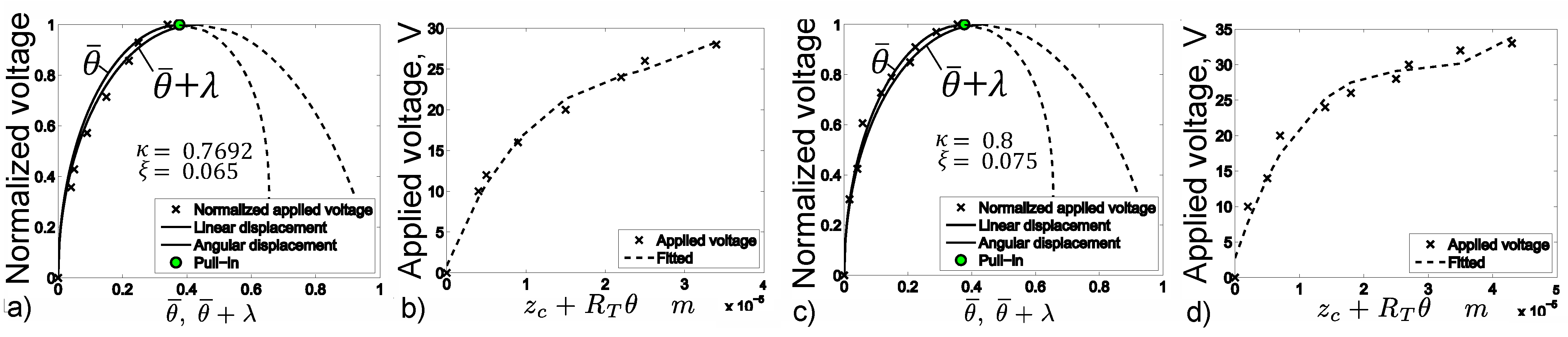
3.3. Model of Static Pull-In of Tilting Actuation

It is assumed that the contribution of the force interaction between the current in the stabilization coil and the eddy current circuit flowing along the edge of the PM to the behavior of the PM in the vertical and angular directions measured by the generalized coordinates z c and θ , respectively, is negligible [27]. Thus, the force interaction between the current in the levitation coil and the eddy current distributed around the PM’s center is dominated and determines the actuation of the PM under applying electrostatic force produced by the energized electrodes “1” and “2”.
Hence, the Lagrangian of the electromagnetic system under consideration can be written as
L = 1 2 m z ˙ c 2 + 1 2 J θ ˙ 2 m g z c + M ( θ , z c ) I i + 1 2 L e ( θ , z c ) i 2 1 2 Q 1 2 C 1 ( θ , z c ) 1 2 Q 2 2 C 2 ( θ , z c ) ,
where m is the mass of PM, J is the moment of inertia of the disc about the axis through center of mass and coinciding with its diameter, g is the gravitational acceleration, M ( θ , z c ) is the mutual inductance defined by Formula (6), I is the given AC current in the levitation coil ( I = I ^ e j ω t , where I ^ is the magnitude, ω is the frequency), i is the induced eddy current, L e is the self inductance of the eddy current circuit, Q 1 and Q 2 are the charges stored by the planar capacitors C 1 and C 2 built on electrodes “1” and “2”, respectively. Accounting for linear and angular displacements of the PM, the capacitances corresponding to circular “1” and sectorial “2” electrode can be described, respectively, by the following equations
C 1 ( θ , z c ) = φ 10 h l + z c tan 2 ( θ ) ln 1 R 1 2 tan 2 ( θ ) ( h l + z c ) 2 ; C 2 ( θ , z c ) = φ 20 tan ( θ ) R o u t R i n + h l + z c tan ( θ ) ln 1 + R i n tan ( θ ) / ( h l + z c ) 1 + R o u t tan ( θ ) / ( h l + z c ) ,
where φ 10 = π ε ε 0 and φ 20 = ε ε 0 π / 2 , ε is the relative permittivity and ε 0 is the permittivity of free space, R 1 is the radius of the center electrode, R o u t and R i n are the outer and inner radii of the sectorial electrode, respectively. Noting that the capacitors are connected in the series, for charges we can write that Q 1 = Q 2 = Q . The dissipation function can be presented as
Ψ = 1 2 R e d d y i 2 ,
where R e d d y is the electrical resistance of the eddy current circuit. Hence, the state of the system can be defined by two coordinates z c and θ , the charge Q and the eddy current i.
Adapting the variables and the assumptions introduced above, the Lagrange–Maxwell equations of the system can be written as follows
d d t L i + Ψ i = 0 ; L Q = U ; d d t L z ˙ c L z c = 0 ; d d t L θ ˙ L θ = 0 .
Substituting (12) and (14) into (15) and accounting for the fact that the static problem is considered, the acceleration and speed of coordinates z c and θ are ignored. Thus, we can finally write the following set of equations describing the static behavior of the PM [26]:
L e d i d t + R e d d y i + M d I d t = 0 ; C 2 + C 1 C 1 C 2 Q = U ; m g M z c I i 1 C 1 + C 2 C 2 2 C 1 z c + C 1 2 C 2 z c U 2 = 0 ; M θ I i 1 C 1 + C 2 C 2 2 C 1 θ + C 1 2 C 2 θ U 2 = 0 .
Since the system operated in the air and the air damping supports the stable levitation of the PM, we can conclude, similar to [26], that i M I / L e . Substituting the relation for currents from the latter conclusion into (16) and averaging ponderomotive force and torque with respect to the time ( 1 / 2 π 0 2 π 1 L e M p ( i ) ( I ) d t = 1 / 2 1 L e M p I ^ 2 , where p = θ , z c ), we can write
m g 1 2 M z c M L e I ^ 2 1 C 1 + C 2 C 2 2 C 1 z c + C 1 2 C 2 z c U 2 = 0 ; 1 2 M θ M L e I ^ 2 1 C 1 + C 2 C 2 2 C 1 θ + C 1 2 C 2 θ U 2 = 0 .

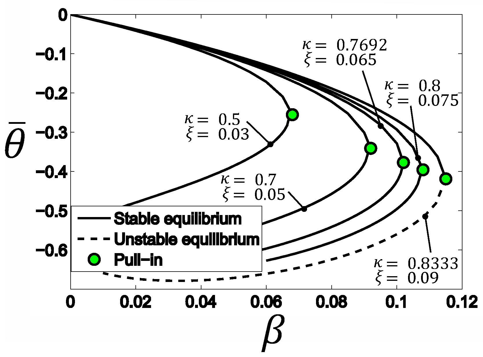
4. Analysis of the Derived Model

In order to describe the static pull-in actuation of the fabricated prototype, the semi-analytical model (17) is developed. The developed model (17) is derived by employing the qualitative technique to analyze inductive contactless suspensions, and a new formula for calculation of mutual inductance between the circular filament and its projection on a tilted plane was obtained in Section 3.2. The obtained new formula for calculation of mutual inductance is the result of simulation of induced eddy current within disc-shaped PM received by means of quasi-FEM approach, which showed that the geometry of the second circuit approximating the eddy current induced within the disc by AC current in the levitation coil is transformed due to the disc tilting.
The mechanical behavior of the disc is described by two generalized coordinates. They can be represented by dimensionless variables, namely, θ ¯ = R T θ / h is the dimensionless angle and λ = z c / h is the dimensionless displacement, where h is the spacing between the surface electrode structure and an equilibrium point O; R T = ( R o u t + R i n ) / 2 is the distance between the center of the disc and applied electrostatic force generated by electrode “2”. The electromagnetic part of this system is reduced to the interaction between the current in the levitation coil and the induced eddy current with circuit corresponding to its maximum density within the disc. As a result of numerical analysis, the behavior of the shape of induced maximum density of eddy current within the disc was represented via an analytical function, which is dependent on the two generalized coordinates introduced above. This circumstance helps us to exactly define the mutual inductance and then to calculate the magnetic force and torque acting on the disc.
A preliminary result of modeling is shown in Figure 4, which provides an evolution of bifurcation diagrams for equilibrium of the titling PM without linear displacement depending on the applied dimensionless voltage β = ε 0 A 1 U 2 / ( 2 m g h 2 ( 1 + a ) ) , where A 1 and A 2 are the areas of electrode 1 and 2, respectively, a = A 1 / A 2 , and depend on dimensionless parameters characterizing geometrical particularities of the prototype design, namely, κ = h / h l , which is in a range from 0.5 to 0.9, and ξ = h l / ( 2 R l ) , which changes in a range from 0.03 to 0.09. These ranges of parameters κ and ξ are typical for all known designs of HLMA studied in the literature. As it is seen from Figure 4, increasing a radius of levitation coil (meaning that ξ is decreased) and decreasing the space h (meaning that the dimensionless parameter κ is also decreased) leads to decreasing pull-in voltage and displacement.
Modeling the experimental measurement discussed in Section 2 requires taking into account the angular as well as linear displacement of the disc due to essential contribution of linear force acting on the disc along the z-axis. Figure 5 presents the results of modeling and measurements of the static pull-in of tilting actuation executed by the micro-actuator for two different levitation heights, namely, 130 and 150 μ m . Data collected during the measurement I and II in absolute values are shown in Figure 5b,d, respectively. Whereas, the results of modeling together with measured data in the normalized values are shown in Figure 5a,c. Analysis of Figure 5 shows that due to the contribution of the linear force, the range of angular displacement is reduced by almost 40% in both measurements.
Furthermore, measured data of pull-in actuation for measurement I and II are shown together with results of modeling in absolute values in Figure 6. Figure 6 provides a conclusive way to estimate the accuracy of the developed model (17) of pull-in actuation in the HLAM by means of direct comparison of results of modeling and measurements. The parameters of the device, particularities of conducted measurements and obtained results are summarized in Table 1. From the analysis of Figure 5 and Figure 6 and Table 1, we can conclude that the results of modeling obtained by means of the developed model are in a good agreement with experimental data.

5. Conclusions

In this article, the static pull-in of tilting actuation in HLMA was studied theoretically, as well as experimentally. The semi-analytical model (17) mimicking the static pull-in behavior of tilting actuation in HLMA is developed by employing the qualitative technique to analyze the dynamics and stability of inductive contactless suspensions, and new formula for calculation of mutual inductance between the circular filament and its projection on a tilted plane. As the result of simulation of induced eddy current within disc-shaped PM carried out using a quasi-FEM approach, which showed the distribution of eddy current around the center of a conducting disc, this new formula was developed and presented in the integral form based on Kalantarov–Zeitlin’s method. The obtained non-linear model, accounting for two degrees of freedom of the actuator, allows us to predict accurately the static pull-in displacement and voltage for the particular prototype of HLMA. The results of modeling were verified experimentally and agree well with measurements. Through this study we verified successfully the given assumptions for modeling and developed the robust analytical tool to describe the static pull-in actuation and to predict pull-in parameters for HLMAs.

Funding

This research was funded by the German Research Foundation grant number KO 1883/37-1 within the priority program SPP2206 “KOMMMA”, project “A 2D array of cooperative hybrid levitation micro-actuators”.

Conflicts of Interest

The author declares no conflict of interest.

Abbreviations

The following abbreviations are used in this manuscript:
ILMAInductive Levitation Micro-Actuator
HLMAHybrid Levitation Micro-Actuator
PMProof Mass
MLMAMagnetic Levitation Micro-Actuator
ELMAElectric Levitation Micro-Actuator

Appendix A. Nomenclature

A 1
area of the electrode “1” ( m 2 )
A 2
area of the electrode “2” ( m 2 )
a 
dimensionless parameter A 1 / A 2
C 1
capacitance of capacitor build on electrode “1” ( F )
C 2
capacitance of capacitor build on electrode “2” ( F )
E 
the complete elliptic function of the second kind
F l
generalized force ( l = 1 , 2 , 3 ) ( N )
g
gravity acceleration vector ( m / s 2 )
h l
height of levitation ( m )
h 
space between the electrode surface and cm of levitated disc ( m )
i 
induced eddy current ( A )
I 
AC current in the levitation coil ( A )
I ^
magnitude of AC current in the levitation coil ( A )
j 
imaginary unit
K 
complete elliptic function of the first kind
N 
number of wire loops
n 
number of finite elements
L 
Lagrange function ( J )
L e
self-inductance of the eddy current circuit ( H )
L j j c
self-inductance of the j-wire loop ( H )
L o
self-inductance of the finite circular element ( H )
L k s c
mutual inductance between k- and s-finite circular elements ( H )
M 
between two filaments of circular and elliptic shapes ( H )
m 
mass of levitated object ( k g )
Q 
electric charges ( C )
R e d d y
electrical resistance of the eddy current circuit ( Ω )
R e
radius of circular element ( m )
R i n
inner radius of sector electrode ( m )
R l
radius of levitation coil ( m )
R o u t
outer radius of sector electrode ( m )
R T
mean distance ( m )
t h
thickness of micro-object ( m )
U 
voltage ( V )
y c
coordinate of the centre of the ellipse along the y-axis ( m )
z c
coordinate of the centre of the ellipse along the z-axis ( m )
  • Matrices
E ̲
unit matrix of size ( n × n )
I ̲
matrix of eddy currents of size ( n × 1 ) ( A )
I ̲ c
matrix of coil currents of size ( N × 1 ) ( A )
M ̲ o
symmetric hollow matrix of size ( n × n ) whose elements are L k s o ( k s ) ( H )
M ̲ c
mutual inductance between coils and finite elements of size ( n × N ) ( H )
  • Greek symbols
β
dimensionless square voltage
θ
angular displacement of the levitated disc ( rad )
θ ¯
dimensionless angle R T θ / h
κ
dimensionless parameter h / h l
λ
dimensionless displacement z c / h
ξ
dimensionless parameter h l / ( 2 R l )
Ψ
dissipation function ( W )
ω
frequency of AC current ( Hz )

References

  1. Jin, J.; Yih, T.C.; Higuchi, T.; Jeon, J.U. Direct electrostatic levitation and propulsion of silicon wafer. IEEE Trans. Ind. Appl. 1998, 34, 975–984. [Google Scholar] [CrossRef]
  2. Murakoshi, T.; Endo, Y.; Fukatsu, K.; Nakamura, S.; Esashi, M. Electrostatically levitated ring-shaped rotational gyro/accelerometer. Jpn. J. Appl. Phys. 2003, 42, 2468–2472. [Google Scholar] [CrossRef]
  3. Han, F.T.; Liu, Y.F.; Wang, L.; Ma, G.Y. Micromachined electrostatically suspended gyroscope with a spinning ring-shaped rotor. J. Micromech. Microeng. 2012, 22, 105032. [Google Scholar] [CrossRef]
  4. Poletkin, K.V.; Asadollahbaik, A.; Kampmann, R.; Korvink, J.G. Levitating Micro-Actuators: A Review. Actuators 2018, 7, 17. [Google Scholar] [CrossRef] [Green Version]
  5. Coombs, T.A.; Samad, I.; Ruiz-Alonso, D.; Tadinada, K. Superconducting micro-bearings. IEEE Trans. Appl. Supercond. 2005, 15, 2312–2315. [Google Scholar] [CrossRef]
  6. Lu, Z.; Poletkin, K.; den Hartogh, B.; Wallrabe, U.; Badilita, V. 3D micro-machined inductive contactless suspension: Testing and modeling. Sens. Actuators A Phys. 2014, 220, 134–143. [Google Scholar] [CrossRef]
  7. Poletkin, K.V.; Lu, Z.; Moazenzadeh, A.; Mariappan, S.G.; Korvink, J.G.; Wallrabe, U.; Badilita, V. Polymer Magnetic Composite Core Boosts Performance of Three-Dimensional Micromachined Inductive Contactless Suspension. IEEE Magn. Lett. 2016, 7. [Google Scholar] [CrossRef]
  8. Shearwood, C.; Williams, C.B.; Mellor, P.H.; Chang, K.Y.; Woodhead, J. Electro-magnetically levitated micro-discs. In Proceedings of the IEE Colloquium on Microengineering Applications in Optoelectronics, London, UK, 27 February 1996; pp. 6/1–6/3. [Google Scholar] [CrossRef]
  9. Xiao, Q.; Wang, Y.; Dricot, S.; Kraft, M. Design and experiment of an electromagnetic levitation system for a micro mirror. Microsyst. Technol. 2019, 25, 3119–3128. [Google Scholar] [CrossRef]
  10. Shearwood, C.; Ho, K.Y.; Williams, C.B.; Gong, H. Development of a levitated micromotor for application as a gyroscope. Sens. Actuators A Phys. 2000, 83, 85–92. [Google Scholar] [CrossRef]
  11. Su, Y.; Xiao, Z.; Ye, Z.; Takahata, K. Micromachined Graphite Rotor Based on Diamagnetic Levitation. IEEE Electron Device Lett. 2015, 36, 393–395. [Google Scholar] [CrossRef]
  12. Garmire, D.; Choo, H.; Kant, R.; Govindjee, S.; Sequin, C.; Muller, R.; Demmel, J. Diamagnetically levitated MEMS accelerometers. In Proceedings of the IEEE International Solid-State Sensors, Actuators and Microsystems Conference (TRANSDUCERS 2007), Lyon, France, 10–14 June 2007; pp. 1203–1206. [Google Scholar]
  13. Dieppedale, C.; Desloges, B.; Rostaing, H.; Delamare, J.; Cugat, O.; Meunier-Carus, J. Magnetic bistable micro-actuator with integrated permanent magnets. In Proceedings of the 2004 IEEE SENSORS, Vienna, Austria, 24–27 October 2004; Volume 1, pp. 493–496. [Google Scholar]
  14. Abadie, J.; Piat, E.; Oster, S.; Boukallel, M. Modeling and experimentation of a passive low frequency nanoforce sensor based on diamagnetic levitation. Sens. Actuators A Phys. 2012, 173, 227–237. [Google Scholar] [CrossRef] [Green Version]
  15. Poletkin, K.V.; Lu, Z.; Wallrabe, U.; Korvink, J.G.; Badilita, V. A qualitative technique to study stability and dynamics of micro-machined inductive contactless suspensions. In Proceedings of the 2017 19th International Conference on Solid-State Sensors, Actuators and Microsystems (TRANSDUCERS), Kaohsiung, Taiwan, 18–22 June 2017; pp. 528–531. [Google Scholar] [CrossRef]
  16. Sari, I.; Kraft, M. A MEMS Linear Accelerator for Levitated Micro-objects. Sens. Actuators A Phys. 2015, 222, 15–23. [Google Scholar] [CrossRef]
  17. Poletkin, K.; Lu, Z.; Wallrabe, U.; Badilita, V. A New Hybrid Micromachined Contactless Suspension With Linear and Angular Positioning and Adjustable Dynamics. J. Microelectromech. Syst. 2015, 24, 1248–1250. [Google Scholar] [CrossRef]
  18. Xu, Y.; Cui, Q.; Kan, R.; Bleuler, H.; Zhou, J. Realization of a Diamagnetically Levitating Rotor Driven by Electrostatic Field. IEEE/ASME Trans. Mechatron. 2017, 22, 2387–2391. [Google Scholar] [CrossRef]
  19. Xu, Y.; Zhou, J.; Bleuler, H.; Kan, R. Passive diamagnetic contactless suspension rotor with electrostatic glass motor. Micro Nano Lett. 2019, 14, 1056–1059. [Google Scholar]
  20. Chen, X.; Keskekler, A.; Alijani, F.; Steeneken, P.G. Rigid body dynamics of diamagnetically levitating graphite resonators. Appl. Phys. Lett. 2020, 116, 243505. [Google Scholar] [CrossRef]
  21. Kratt, K.; Badilita, V.; Burger, T.; Korvink, J.; Wallrabe, U. A fully MEMS-compatible process for 3D high aspect ratio micro coils obtained with an automatic wire bonder. J. Micromech. Microeng. 2010, 20, 015021. [Google Scholar] [CrossRef]
  22. Vlnieska, V.; Voigt, A.; Wadhwa, S.; Korvink, J.; Kohl, M.; Poletkin, K. Development of Control Circuit for Inductive Levitation Micro-Actuators. Proceedings 2020, 64, 39. [Google Scholar] [CrossRef]
  23. Poletkin, K.; Lu, Z.; Wallrabe, U.; Badilita, V. Hybrid electromagnetic and electrostatic micromachined suspension with adjustable dynamics. J. Phys. Conf. Ser. 2015, 660, 012005. [Google Scholar] [CrossRef] [Green Version]
  24. Poletkin, K.V. A novel hybrid Contactless Suspension with adjustable spring constant. In Proceedings of the 2017 19th International Conference on Solid-State Sensors, Actuators and Microsystems (TRANSDUCERS), Kaohsiung, Taiwan, 18–22 June 2017; pp. 934–937. [Google Scholar] [CrossRef]
  25. Poletkin, K.V.; Shalati, R.; Korvink, J.G.; Badilita, V. Pull-in actuation in hybrid micro-machined contactless suspension. J. Phys. Conf. Ser. 2018, 1052, 012035. [Google Scholar] [CrossRef] [Green Version]
  26. Poletkin, K.; Lu, Z.; Wallrabe, U.; Korvink, J.; Badilita, V. Stable dynamics of micro-machined inductive contactless suspensions. Int. J. Mech. Sci. 2017, 131–132, 753–766. [Google Scholar] [CrossRef] [Green Version]
  27. Poletkin, K.V. Static Pull-In Behavior of Hybrid Levitation Microactuators: Simulation, Modeling, and Experimental Study. IEEE/ASME Trans. Mechatron. 2021, 26, 753–764. [Google Scholar] [CrossRef]
  28. Poletkin, K.V.; Korvink, J.G. Efficient calculation of the mutual inductance of arbitrarily oriented circular filaments via a generalisation of the Kalantarov-Zeitlin method. J. Magn. Magn. Mater. 2019, 483, 10–20. [Google Scholar] [CrossRef] [Green Version]
  29. Poletkin, K.V.; Korvink, J.G. Modeling a Pull-In Instability in Micro-Machined Hybrid Contactless Suspension. Actuators 2018, 7, 11. [Google Scholar] [CrossRef] [Green Version]
  30. Poletkin, K. Simulation of Static Pull-in Instability of Hybrid Levitation Microactuators. In Proceedings of the ACTUATOR; International Conference and Exhibition on New Actuator Systems and Applications 2021, Online, 17–19 February 2021; pp. 1–4. [Google Scholar]
  31. Poletkin, K.V. Levitation Micro-Systems: Applications to Sensors and Actuators, 1st ed.; Springer International Publishing: Cham, Switzerland, 2020; p. 145. [Google Scholar] [CrossRef]
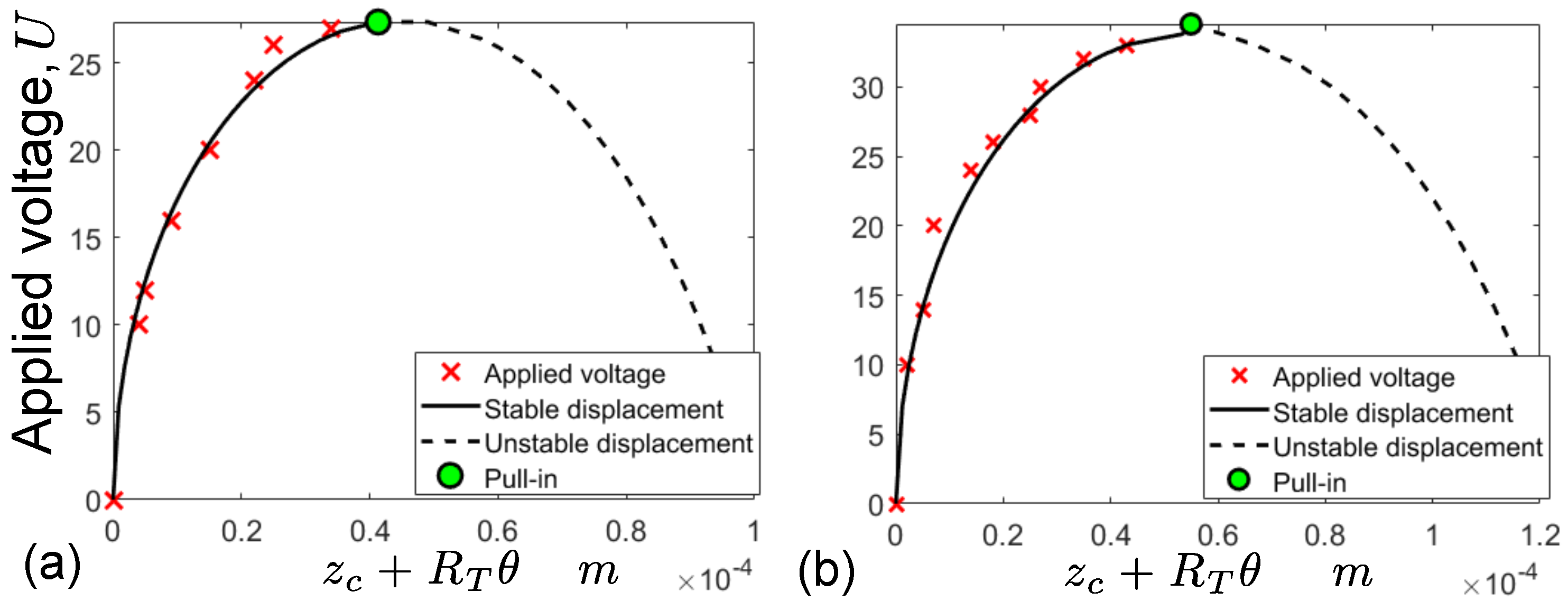
Figure 1. The prototype of micro-actuator-performed tilting pull-in actuation: (a) the fabricated prototype of the micro-actuator glued and wire-bonded on a PCB board and levitated stably micro-disc with a diameter of 2.8 mm; (b) the set of electrodes fabricated on the top of the silicon structure: the energized electrodes generating the electrostatic forces executing the pull-in actuation are highlighted in red, where U is the applied voltage; (c) video frames demonstrating actual tilting pull-in actuation: the top figure shows the original flat state of the micro-disc and the bottom figure shows its tilted state after applying the pull-in voltage.
Actuators 10 00256 g001
Figure 2. Simulation of eddy current: (a) the disc is meshed by circular elements n = 2496 , { x k } ( k = 1 , 2 , 3 ) is the coordinate frame assigned to the center of disc; (b) 3D schematic diagram of the actuator; (c) 3D plot of the distribution of dimensionless magnitude of the eddy current along the surface of the disc; (d) 2D plot of the distribution of magnitudes of eddy current.
Actuators 10 00256 g002
Figure 3. Reduced scheme for modeling electromagnetic interaction between the levitation coil and the tilt-disc: h l is the levitation height between a plane of coils and equilibrium point; θ is the tilting angle; i e is the induced eddy current corresponding to the maximum current density within the disc; R l is the radius of the levitation coil; z c = z c ( θ ) and y c = y c ( θ , z c ) are the coordinates of the center of the ellipse as functions of generalized coordinates; b = b ( θ ) is the length of minor axis of the ellipse.
Actuators 10 00256 g003
Figure 4. Stable and unstable angular equilibrium of the tilt-disc and its evolution depending on the parameters of device such as ξ = h l / 2 R l and κ = h / h l , where h is the space between an electrode plane and equilibrium point of the disc, R l is the radius of levitation coil.
Actuators 10 00256 g004
Figure 5. The results of modeling together with measured data in the normalized values: (a) measurement I; (c) measurement II. Applied voltage vs. the linear displacement of the disc: (b) measurement I; (d) measurement II (other details are shown in Table 1).
Actuators 10 00256 g005
Figure 6. Measured data and results of model=ling in absolute values: (a) for measurement I; (b) for measurement II (other details are shown in Table 1).
Actuators 10 00256 g006
Table 1. Results of measurements and modeling of the static pull-in.
Measurement IMeasurement II
MeasuredLevitation height, h l 130 μ m 150 μ m
parametersSpacing, h100 μ m 120 μ m
Results
of medelling
Pull-in displacement34 μ m 45 μ m
Pull-in voltage,U27 V 33 V
Parameters
of medelling
ξ = h l / d l 0.0650.075
κ = h / h l 0.76920.8
Results
of medelling
Pull-in displacement38 μ m 48 μ m
Pull-in voltage,U28 V 33 V
Device designDiameter of levitation coil, d l 2 m m
Area of electrodes, A 1 and A 2 0.8 and 0.43 m m 2
Publisher’s Note: MDPI stays neutral with regard to jurisdictional claims in published maps and institutional affiliations.

