1. Introduction
E-David is an automatic painting system that uses an industrial robotic arm and a visual feedback system to create paintings. It can easily be adapted to varying painting styles, tools, surfaces and paints. Based on an input photo, the system creates a set of brush strokes and executes them using the robot arm. E-David aims to approximate the human painting process (
Deussen et al. 2012). A variety of painterly rendering algorithms have been developed to work within the feedback-loop, in which the robot periodically takes a photograph of its progress and determines which actions to take based on the difference between the canvas and input image
Lindemeier et al. (
2013). These capabilities make e-David much more than just a printer capable of reproducing flat images, as it creates unique works through the application of paint strokes that are irreproducible in terms of colour blending and materiality of their layering. The possibility of visual feedback opens up many interesting questions within the contemporary discourse on deep learning, artificial intelligence and robotic creativity. One of them is the optimization of the painting process by eliminating unnecessary strokes in order to mimic a human’s efficiency when painting
Lindemeier et al. (
2015).
Currently, the system uses a fairly static approach to painterly rendering. Strokes are painted with a brush held at a constant distance to the canvas throughout the entire process. The application pressure is never changed and the stroke width can only be varied by switching between brushes of different sizes. Furthermore, strokes are fully computer-generated for each image. Artists working with e-David have often expressed the desire to introduce their own strokes, which the system would then replicate. Knowledge about how a certain brush movement produces a stroke is also not retained. These limitations of the robot’s painting technique decreased both the artistic and scientific usefulness of the machine, because much of the finesse required for detailed painting was lacking. The new methods presented in this paper allow for a much more controlled placement of strokes and thus more detailed and varied paintings.
In order to enable e-David to precisely draw strokes, we have developed several new methods designed to mimic the human process of painting. The first method involves measuring the width of a stroke produced by a brush at a certain application pressure. This allows the creation of pressure profiles that map the distance of the brush from the canvas to the width of the stroke. We then generalised this technology to measure the width of non-overlapping strokes of nearly any shape and size, as well as the movement used to paint them. Using knowledge acquired by the these two methods, a reproduction step was developed that recreates a stroke created by a human as closely as possible. Finally, we implemented a process that automatically improves the reproduction result by correcting deviations between the target stroke and the result. Each attempt is stored in a stroke database for later use in machine learning projects or as a repertoire for future painting.
On the artistic side of the project, Liat Grayver has been collaborating with the e-David team during the past three years in order to investigate methods to redefine one of the primitive forms of art—painting—in our current technology-based era. Specifically, this includes investigating new methods for the application of paint on canvas and for using computer-assisted generation of physical images. More broadly, the work aspires to harness computers and machines to establish new and innovative avenues in contemporary artistic practices. Grayver states:
“One of the aspects of artistic practice in general, and painting in particular, is the attempt to manifest one’s own personal or intimate perspective through materials into the public and social discourse. This is not only about the form or the finished object, but also about the process, the perspective and perception of a structure—all of which is defined by our dynamic surroundings and contemplated through the tools, mediums and technology of the present time and local place.”
One could claim that the history of art and culture is aligned with the history of technological innovation. The creation of painting machines is an attempt to explore and create new methods of human expressiveness; making the machine to be, in a way, more compatible to human playfulness and creativity. A painting robot seeks to achieve a result that could be experienced and felt as similar to the human way of painting. In other words, something that is aligned to the duality one can find in a work of art: a level of randomness balanced with precision and expressivity merged with a complex mathematical architecture.
In the following, we provide an overview of painting machines, from the earliest works in the 1760s up to contemporary devices, followed by a brief history of e-David and works produced by the machine. Finally, aspects of brush control and single stroke reproduction are discussed from both a technical and an artistic point of view.
3. E-David
E-David (An acronym for “Electronic Drawing Apparatus for Vivid Image Display”) is the robotic painting system that has been under development at the University of Konstanz since 2008.
It has several features that distinguish it from other painting machines. An optical feedback system integrates information about the current canvas state into the painting process. E-David also has the ability to handle a large number of paints, to switch between brushes and to utilise sophisticated brush-cleaning methods for a cleaner result. Recent results can be seen in
Figure 3. E-David is not a single machine, but rather a complex system consisting of hardware and software components.
3.1. Hardware
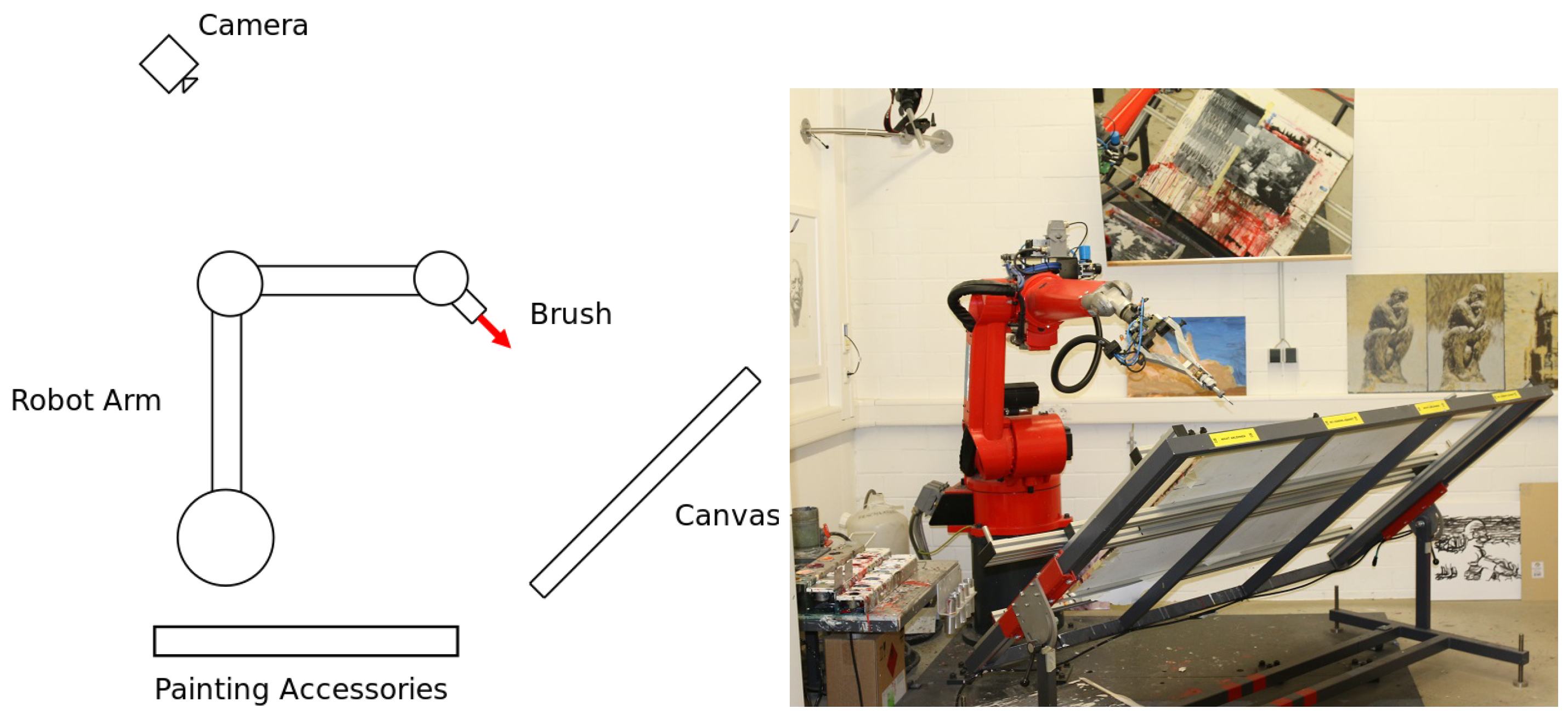
E-David consists of a robotic arm mounted in front of a canvas. A brush is held by the arm and serves as the end effector. An accessory table holds a palette of colours that the robot dips the brush into, as well as mechanisms to clean and dry the brush before switching to another paint. A camera is positioned behind the setup such that it has a full view of the canvas, so feedback photos can be taken. These are used by the painting software described in the next section.
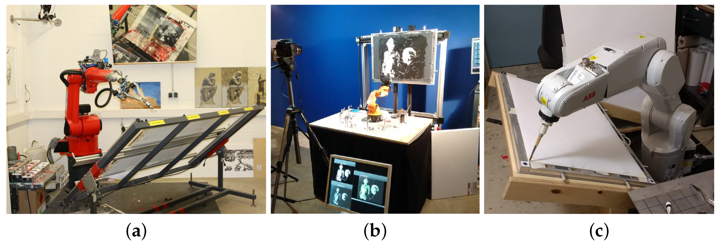
The main robot used by the project is a a Reis RV-20 6, which is intended for welding applications and machine tending. See
Figure 4 for a photo of this device. The robot is also permanently bolted to the laboratory floor due to its weight and thus cannot be transported for events such as exhibitions. A mobile version, called “e-David Mini”, was built using a small KUKA YouBot that was able to demonstrate the painting process in various locations. This setup has been demonstrated in Luzern in 2014 at the Swiss ICT award, and an upgraded version was shown in Leipzig in 2016 at an art exhibition
Halle 14 (
2017). A photo of the setup can be seen in
Figure 4b. The YouBot turned out to be unsuitable for further work, as it lacks one degree of freedom, has no control software and developed mechanical defects after some use. Hence a new robot, the ABB IRB 1200 (see
Figure 4c), has been acquired. A in-depth description of the technical aspects of the robots used can be found in
Section 9.
3.2. Painting Software
After being given a digital image, e-David is capable of reproducing this target picture on a canvas using any paint that can be applied using a brush or a similar tool.
This painting approach is based on a
visual feedback loop. The camera placed behind the robot provides a photograph of the current canvas state. By analysing differences between the current canvas state and the target picture, new strokes are computed and the robot is instructed to perform them. After a batch of strokes has been applied, a new feedback photo is taken and a new round of strokes is computed. This process repeats until the canvas looks similar enough to the input image. In each round, strokes are computed using a method similar to the Hertzmann algorithm
Hertzmann (
1998). The robot starts out with a large brush and performs several iterations. After each one, it switches to the next smaller brush, thus first generating a background followed by details layered on top.
A further benefit of the feedback loop is that it allows for error correction during the painting process. When the robot paints, inaccuracies in the painting occur due to deforming brushes, dripping paint and other hard-to-predict behaviours of the painting implements. Human painters circumvent these issues by avoiding certain behaviours based on experience, such as not keeping the brush too wet to prevent dripping, and by detecting mistakes visually after they have occurred and correcting them. While an effort is made to avoid defects in the painting through appropriate hardware design, some will inevitably occur. For example, the feedback mechanism detects a drop of paint as a colour mismatch and will draw over it using the correct colour.
The system is designed in such a way that any robot capable of applying paint to a canvas and providing feedback pictures can be used as an e-David robot. Only a driver, which translates between the e-David software painting commands and the robot, is required to be implemented for each machine. This is why there were no major redesigns required to accommodate a new robot. Today, the same software (save for the driver) operates both the RV-20 and the IRB 1200.
4. Methods
The general principle behind the current painting approach is to layer many strokes of thin paint upon each other. This allows the process to slowly converge onto the goal image. Strokes are placed according to a Voronoi-based optimization method, described in
Lindemeier et al. (
2015), which allows strokes to be arranged in a natural pattern and to adapt to their neighbouring strokes. The process is further extended through semi-automatic decomposition into layers for sharp corners and back-to-front painting
Lindemeier et al. (
2016).
The current process has several disadvantages. While up to five brushes of different size can be used by switching between them, the application pressure at which they are used is always constant. However, by varying the pressure, it is possible to achieve a continuous range of stroke width and to even vary width within a stroke. This is often used by human artists for detailing. Furthermore, the system does not take brush dynamics into account, so that brush deformation and other effects lead to the actual stroke deviating by several millimetres from the intended location. This effect becomes less visible when multiple layers of paint are applied, but makes detailing difficult.
In order to improve upon these issues, we explored new techniques for the precise placement of single strokes. The goal of the techniques described in the following sections is to develop a better robotic handling of difficult tools like brushes, and to include knowledge about their behaviour in order to achieve more precise results.
4.1. Physical Properties of Brushes and Stroke Width
When a brush is used to apply colour to a canvas, it deforms and changes its shape. This determines how colour is applied to the canvas. A human painter naturally varies the pressure of the brush hairs on the canvas in order to adjust the resulting stroke properties.
The e-David system has so far used a constant pressure for most created paintings, i.e., the brush is always kept at a constant distance from the canvas. Hence, stroke width is only dependent on the brush type and there is no variation within a stroke. A preprogrammed pressure ramp is used at the beginning and end of a stroke in order to make it look more natural, but the width remains constant for the main body of the stroke.
While brushes of various kinds are essential in many production environments, very little academic research has taken place concerning the exact prediction of brush deformation
Przyklenk (
2013). Many virtual brush models exist, however, with the most prominent being introduced by W. Baxter in 2004
Baxter and Lin (
2004). This model treats a brush as a small set of polygonal strips that are simulated kinematically as several external forces act upon them. The resulting simulation is very useful in a virtual painting environment, but the simulated brush does not correspond to a real brush in a way that would allow predictions about the behaviour of the real brush. A realistic simulation of a brush that predicts its behaviour precisely enough for use with the robot would need to account for many parameters, for example bristle material, previous deformation, paint viscosity and so on.
Using a brush with today’s industrial robots is problematic. The kinematic models used to coordinate the movement of robotic arms all require that the robot’s tool has a so-called
tool centre point (TCP). The TCP is assumed to be a static point solidly attached to the robot’s end effector, which holds true for common devices like welding guns, drills or grippers—but not for brushes. Due to deformable bristles, the tip of a brush may vary in position after every stroke and the entire body of the bristles can be employed for transferring paint. Because brushes violate the assumptions of solid TCP of industrial robots, we have developed several compensation methods for e-David that account for variations in tool location. The first method accounts for stroke width as a function of pressure, while the second corrects for brush hairs dragging along the paper. The second method is described in
Section 4.5.
4.2. Visual Feedback and Stroke Processing
The feedback camera is calibrated before use in order to obtain usable images for stroke analysis. The calibration process accounts for lens distortion, external lights and colour variations between cameras.
Lens distortion is corrected through a separate calibration process, during which a calibration panel of known size is placed in several locations. Using 25 or more calibration pictures a reprojection matrix is computed and the image can be rectified. This is necessary in order to obtain a canvas image in which distances between points are consistent, independent of their location in the frame.
Afterwards the canvas is calibrated for lighting, by placing a blank paper of uniform colour onto it. Differences in brightness are measured and a light map is generated, which is used to brighten dark areas in feedback images. This does not correct for glare, which can occur on wet paint and in general a soft, consistent light is still required for the feedback process to work.
The final calibration step is a colour correction. A calibration target of known colour is placed upon the canvas and a picture is taken. The resulting image is then compared to the known values and a colour transformation matrix is computed which can be used for subseqent feedback images.
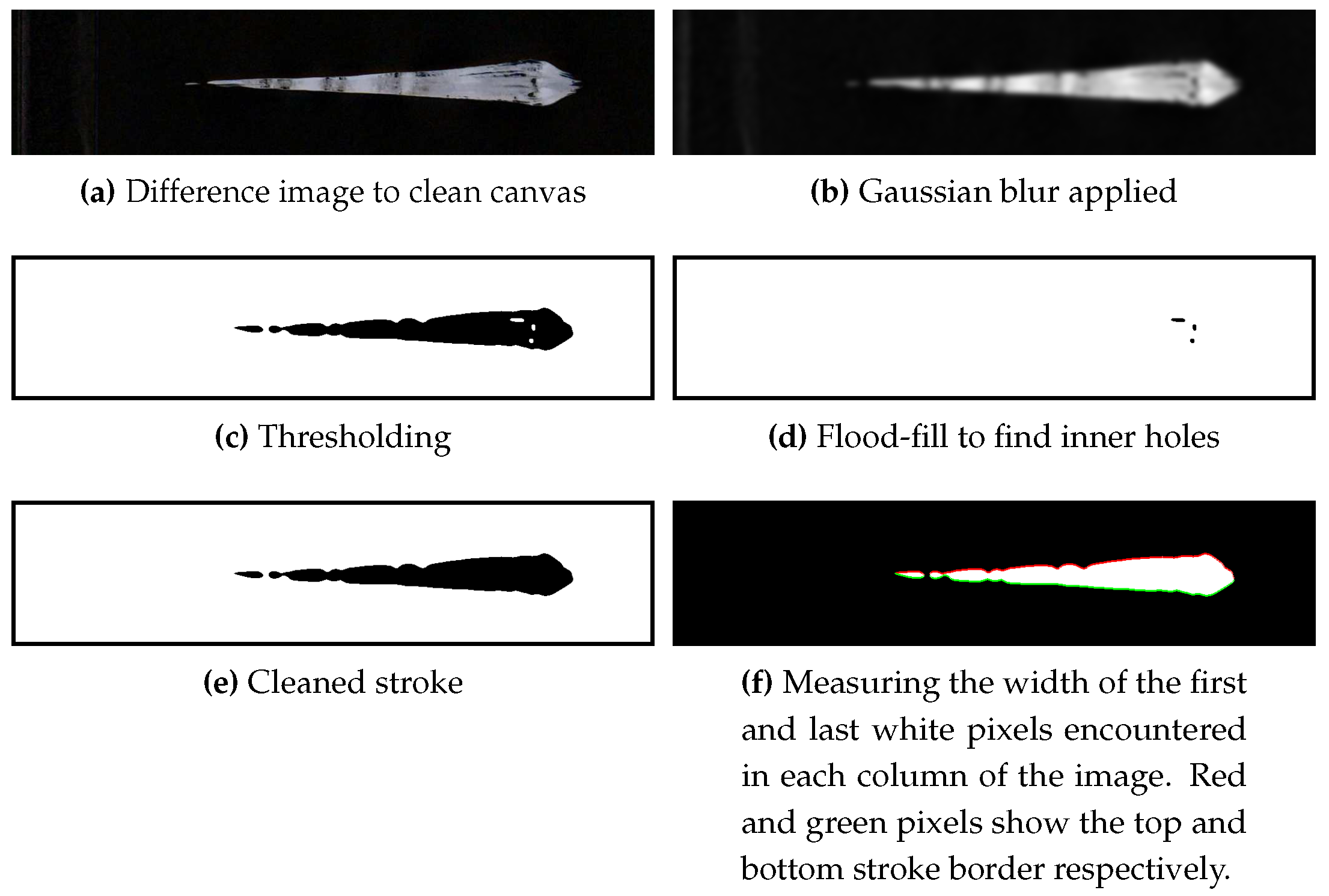
Given the enhanced canvas feedback photo, a certain canvas region is specified as the input area. This subimage is thresholded in order to separate the stroke from the background. Otsu’s method is used for thresholding. It automatically finds an adaptive threshold value by searching for an optimal partition of pixels in the image, based on the intensity distribution in the histogram
Otsu (
1979). While Otsu’s method does have a certain bias and may not produce the optimum threshold
Xu et al. (
2011), it is sufficient for the black-on-white brushstrokes used here and even works with coloured strokes. The method has proven to be much more robust than a fixed thresholding value.
Afterwards, internal holes of the stroke are filled, as these are assumed to be defects caused by the brush running out of paint locally or even splitting.
Gaussian blurring is then applied in order to reduce the influence of certain stroke features on the result. These are small gaps within the stroke or frays caused by some brush hairs separating from the main brush body. However, the blurring may not be too strong, as this can remove thin parts of a stroke, which should be preserved. Hence the kernel size of the blurring algorithm is chosen to be 0.025 times the maximum dimension of the image. This value has been determined experimentally
2 and works well for many kinds of strokes.
Using the thinning algorithm described in
Zhang and Suen (
1984), the strokes are reduced to single-pixel lines. Thinning a pixel image removes outer layers of an area until it is reduced to a topologically equivalent skeleton with a width of one pixel
Baruch (
1988);
Hilitch (
1969). The implementation of this technique has been taken from
Nash (
2013).
After having obtained the thinned image (see
Figure 5), it is much easier to identify the beginning and endpoints of a stroke. These are simply white pixels with only one neighbour. While some cases exist where the start or end pixel can have two neighbours, for a first decomposition method it is robust enough. Beginning from the starting pixel, the line is followed by going from the current pixel to the next neighbouring one which hasn’t been visited yet. This avoids getting stuck in a loop. The walk terminates if an end pixel is reached. If a pixel without unvisited neighbours is encountered but unvisited pixels exist, the algorithm backtracks, until it finds a pixel with unvisited neighbours. This corresponds to a depth-first search
Tarjan (
1972) and ensures that the full stroke is always explored. By doing this for every starting pixel, all possible ways to paint a stroke are found.
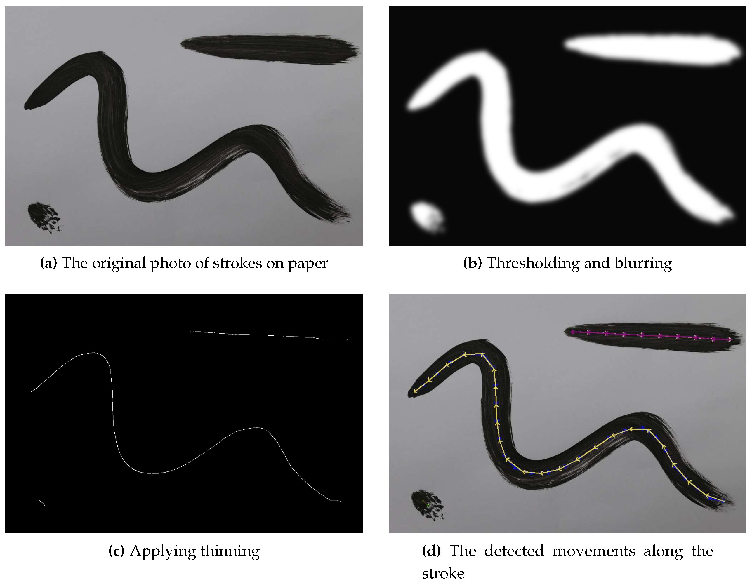
An example trajectory extraction can be seen in
Figure 5. The original
Figure 5a contains several strokes of varying shape and size. The lighting is not perfect and the centre stroke contains several defects. The hole filling and blurring (
Figure 5b) removes most of them. The thinned
Figure 5c exactly matches the strokes in the image, even the very noisy dot in the bottom left. Finally,
Figure 5d shows the detected trajectories as a sequence of small arrows, which represent the calculated robot movements. Note that both possible directions are drawn, as the original direction cannot be reliably inferred from a stroke. Even humans cannot reliably guess whether the top right stroke was drawn from left to right or right to left without prior knowledge. In this case it was drawn starting from the right.
For use by the robot these 2D stroke trajectories in pixel space are transformed into 3D vectors in millimetres. Since both the canvas size in millimetres and the image size in pixels are known, a pixel coordinate can be transformed to its corresponding X/Y location in millimetres with a simple linear transformation.
4.3. Stroke Width Calibration
In order to calibrate stroke width, we first devised a technique for measuring how a brush behaves when it is applied to a canvas with varying pressure. In this case, the stroke width generated at certain pressures is of greatest interest. In the following, the term “brush pressure” is used to describe how firmly a brush is applied to the canvas by the robot rather than the physical pressure exerted on the bristles. The application is characterised by how far the robot TCP moves behind the canvas plane in millimetres. For example, at 0 mm, the tip is just barely touching the canvas and the brush is not deformed. At 2 mm the robot moves the TCP behind the canvas plane, i.e., the brush is held even closer to the canvas. Due to this collision, the brush hair deforms and the deformation increases as the TCP is moved forwards. For brevity, this is described as the “brush pressure in millimetres”.
In order to control the variation of thickness within a stroke, the relationship between applied pressure and delivered thickness must be known for the current brush. Since commonly used paint brushes aren’t manufactured to high precision standards
3, each brush must be measured individually. To this end a fully automatic process has been developed that determines the breadth of a stroke at a certain brush pressure.
The brush starts out 5 mm away from the canvas surface and is held perpendicular to it. The distance is reduced at a known rate while the brush is moved along a straight line at constant velocity, using the robot’s linear path motion functionality. This yields a stroke on the canvas of increasing width. Within this stroke, the distance between brush and canvas is known at every point, which creates a map between pressure and resulting stroke width. By repeating this process several times, errors caused by external factors, such as clumping paint or a deformed painting surface can be minimised. The result of this procedure can be see in
Figure 6.
After painting the calibration strokes, a photo of the canvas is taken. Note that the calibration is robust against any background features, as only the calibration area is considered. Hence even a “noisy” canvas can be used, e.g., by placing a blank sheet of paper over it. A difference image is created by subtracting the resulting image from a photo of the canvas before painting the calibration strokes. This isolates the new strokes and makes it possible to use any colour for the calibration process, as long as it is sufficiently distinct from the background colour.
After some additional processing of the strokes, as seen in
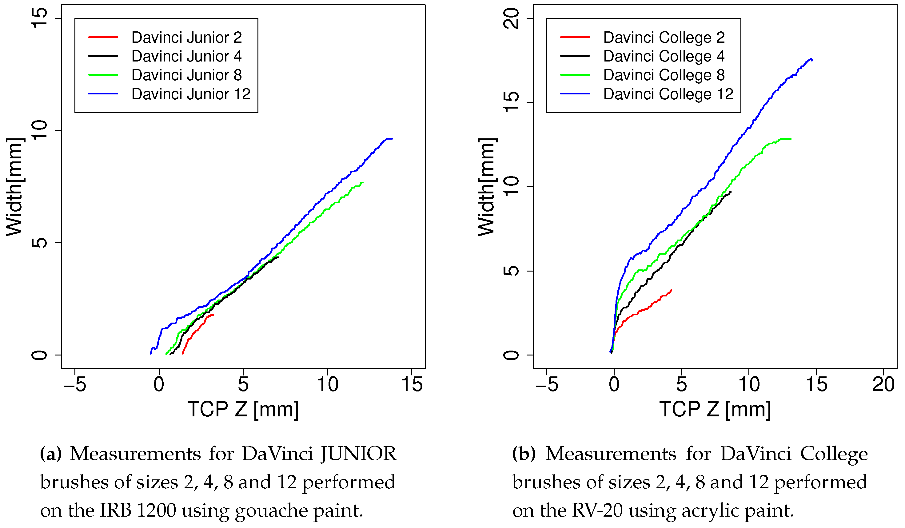
Figure 6, their width in pixels is measured in each available pixel column. The actual width in millimetres can be calculated, as the scale of camera pixels to millimetres on the canvas is already known. By collecting all these values, a table mapping pressure to width is created and stored for later use to determine the necessary Z for a desired width. A plot of measured values can be seen in
Figure 7a,b.
In general, this methods yields good results: the detected widths were verified by measuring the calibration strokes with a calliper and no deviation was detected within a precision of mm. This is in line with the camera’s resolution of about pixels per millimetre.
After a calibration run, the robot was able to draw strokes of a selected width with a precision of
mm to
mm, depending on the brush. Each brush has a range in which it performs best. For example, the DaVinci Junior 12 works well for strokes around 1 cm in width and becomes less precise for smaller widths around 5 mm, where the Junior 8 performs much better. Extremely fine strokes down to a width of
mm can be painted. The error introduced by the robot is negligible in this, as it has a positioning repeatability of ±0.03 mm at its maximum speed of
m s
−1 ABB (
2017b). Since the calibration is done at a TCP velocity of 100 mm s
−1 the robot can be expected to be more precise than the specified maximum error.
Accurate results were also obtained by using a linear model obtained from a regression on the data: the largest observed error between predicted and measured width was mm with the largest brush. Smaller brushes, which are used to paint smaller features, show significantly lower errors. Stroke calibration is now done routinely for each new brush and stroke precision is highly repeatable, as so far no errors beyong the stated bounds have been observed.
A limitation of this method is the assumption that the painting surface starts out and remains flat throughout the painting process. However, materials such as paper are prone to warping, especially when water is applied to the surface along with paint. Another issue is the unpredictable flowing of paints such as ink, which quickly follows moisture in a paper canvas. For now, acrylic and gouache paint have been used for their predictable behaviour and limited warping of the canvas.
The data obtained here provides the basic information about brush behaviour that is required for stroke reproduction and self-improvement methods. For future work in robotic painting, this approach can be used to enable the machine to use a much more human-like approach to brush control.
4.4. Stroke Reproduction
The goal of the reproduction step is for the robot to recreate a stroke as precisely as possible when given only a photograph of the target stroke. This enables users to paint a stroke they would like to use in an image and have the robot store it for later use. Each reproduction also yields data about the difference between the target stroke and the reproduction result, which can later be used as a dataset for machine learning algorithms.
Through this feature, the robot gains the ability to produce a known stroke anywhere on the canvas. This is useful to create both patterns and details: repetition of a stroke can yield a surface with a certain structure. Placing a specific stroke in a precise location can be used by a painting algorithm to deliberately introduce detail or to speed up the painting process. This is in contrast to the current state of the art of placing strokes in a less directed way, which sometimes causes paintings to lack detail and sharp lines.
The reproduction of a stroke happens in four steps:
The user paints a stroke on the canvas in a given region on the canvas. This should be a non-overlapping stroke, as the method cannot handle self-intersections.
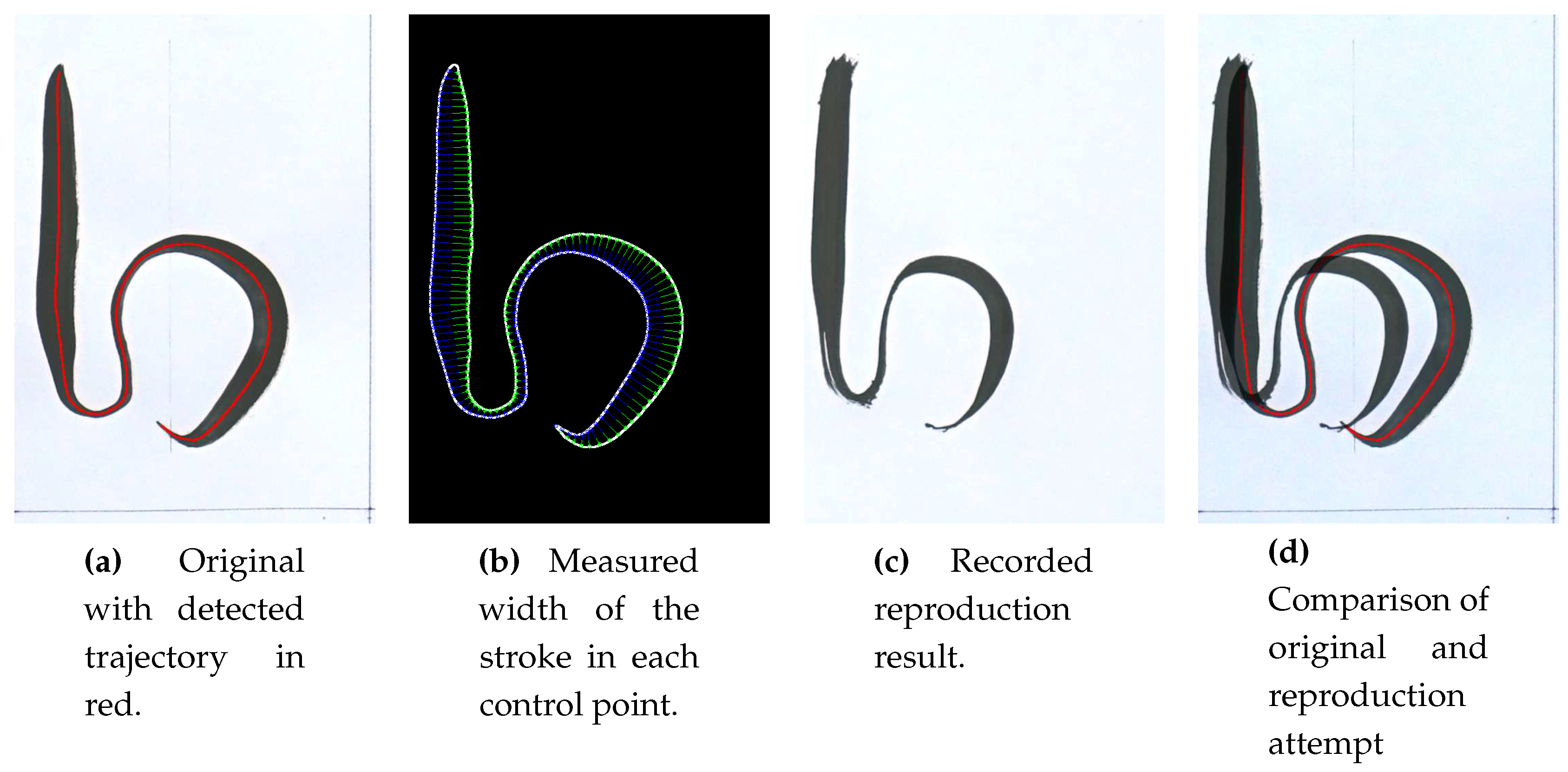
The robot takes a photo of the canvas and analyses the stroke by detecting its centreline. The stroke width profile is determined by using a version of the previously described width measurement, generalised for curved strokes.
The width profile is used to determine the Z-coordinates of the TCP along the trajectory. Since the width calibration described in
Section 4.3 provides the stroke width achieved by a brush at a certain Z-coordinate, a simple lookup can be performed to determine the required brush pressure at each point in the stroke.
The stroke trajectory and required pressure at each point are combined into a 3D trajectory, which is then passed to the robot. It paints the stroke and takes a picture of the result for later evaluation. This yields information about the discrepancy between brush movement and resulting stroke.
Figure 8 shows an example reproduction. The chosen example is a fairly complex stroke that was painted using a brush with 12 mm long bristles, which deform significantly. Despite these obstacles, the achieved result is quite close to the original. In
Section 4.5 a method is discussed that minimises these divergences. Stroke reproduction is highly repeatable, as long as the input stroke is of high enough quality. For example a “hollow” brush stroke, where the brush has run out of paint, cannot be be used or will cause the robot to attempt a reproduction of several strokes.
4.5. Experimental Stroke Improvement
Despite working well in simple strokes, the reproduction process still suffers from inaccuracies in more complex strokes due to unknown brush dynamics. While the reproduced strokes can already be used for writing, the present deviations are an issue for other tasks. For example, if a specific detail like an eyebrow is to be painted in a portrait, even small errors can alter the overall impression. For this reason, we considered several possible solutions for e-David to increase precision.
One of these attempted to measure brush behaviour along curves in a similar fashion to the pressure-to-width calibration. The acquired data could be used to create a brush model that predicts the cornering behaviour of measured brushes. The measurement, however, would have to be made for a number of curve radii and pressure levels, which would have required an impractically large number of samples. Hence we decided not to use this approach of simulation.
Instead of virtual simulation we investigated a method for physical experimentation directly on paper. Physical experimentation has been used before in autonomous robot experimentation for biochemical research: for example, the ADAM robot, built by Sparkens et al. is a “robot scientist” that can autonomously formulate hypotheses about gene expression in yeast and then check these in a robotic laboratory, without human intervention
Sparkes et al. (
2010).
In our case physical experimentation is achieved by painting directly on paper and checking the result using the visual feedback system. The robot is given a
stroke prototype, which has been painted onto the canvas by a human. The robot records this stroke using its feedback camera. Using the method described in
Section 4.4, an initial
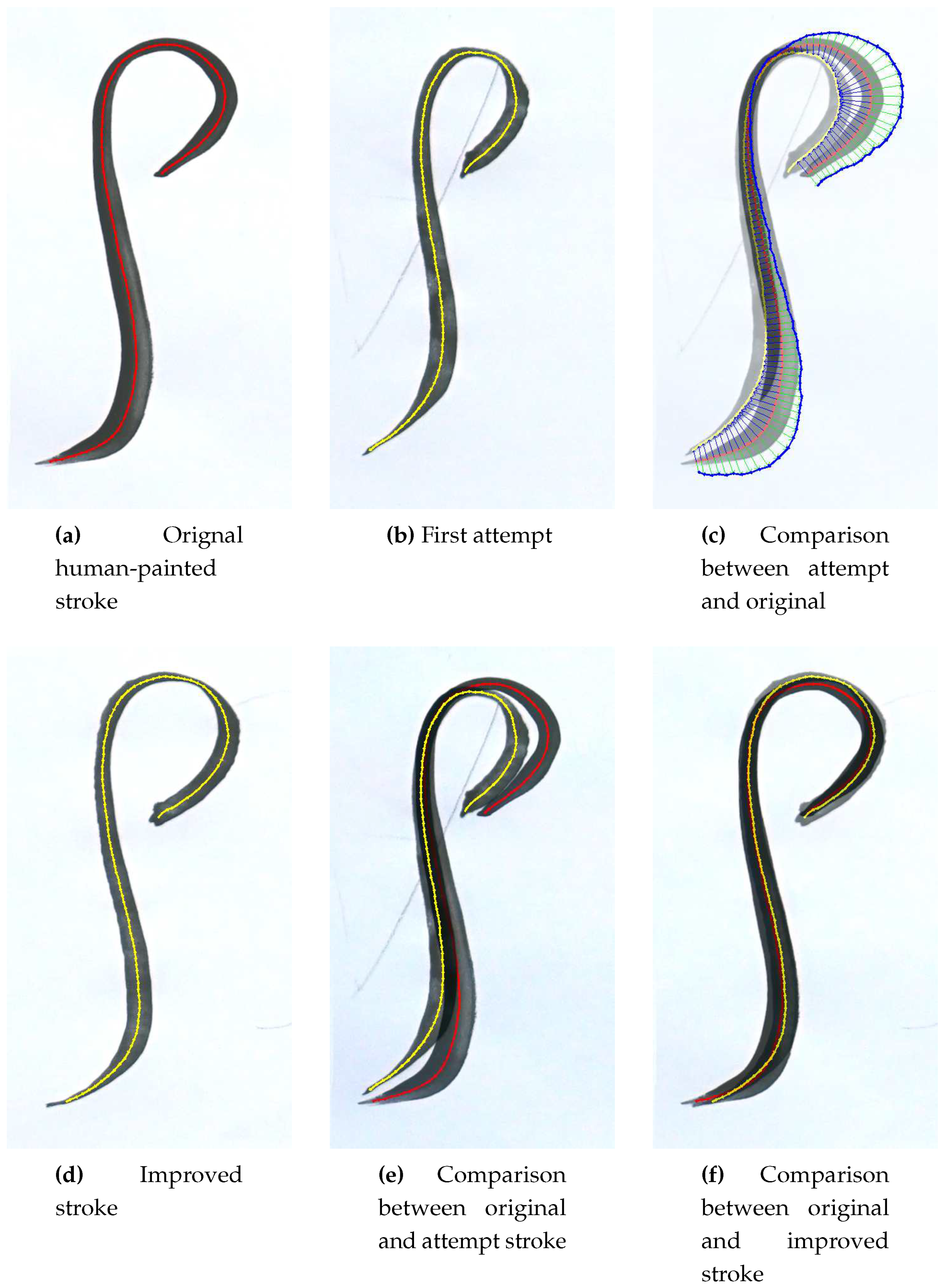
attempt stroke is painted. Through observation of the difference between prototype and attempt, a new trajectory is computed. The experiment consists of painting this improved trajectory and recording the result. By repeating this process several times, the similarity of the attempt to the prototype stroke should increase.
Two strokes are compared by overlaying them. Their trajectories are computed and the deviation of the attempt from the prototype is determined in each point of the prototype. This is done by scanning along a line orthogonal to the prototype trajectory until the attempt trajectory is hit. Some special cases, like finding a correspondence to an unrelated part of the other stroke, must be considered. After discarding erroneous measurements, a new point is created for each control point in the original stroke. The new points are offset in the opposite direction of the measured deviation, which corrects for the deformed brush lagging behind the intended trajectory. For example, in areas of high curvature in the prototype stroke, the first attempt will commonly undershoot and be quite flat. In this case, the correction algorithm creates a more sweeping movement, bringing the brush to the correct location on the canvas.
5. Results
The work presented thus far is a step towards improving the brush handling capabilities of e-David. Fine-tuning the painting technique on a single-stroke level is an important part of producing results that is more similar to human works. The contribution here is threefold:
First, through the measurement of brush behaviour w.r.t. pressure, a primary characteristic of the utilized tool is included in the painting process. This allows adaptation to the complex dynamics of a paint brush and thus greater variation of stroke geometry. Second, stroke reproduction from visual examples is a new method for providing stroke data to the robot. It allows extending the robots capabilities via a demonstration instead of actual programming. Third, the experimental improvement of strokes as demonstrated here is the first step towards a self-teaching painting robot that can learn craftsmanship from own experimentation based on human guidance through example strokes.
5.1. Stroke Reproduction Results
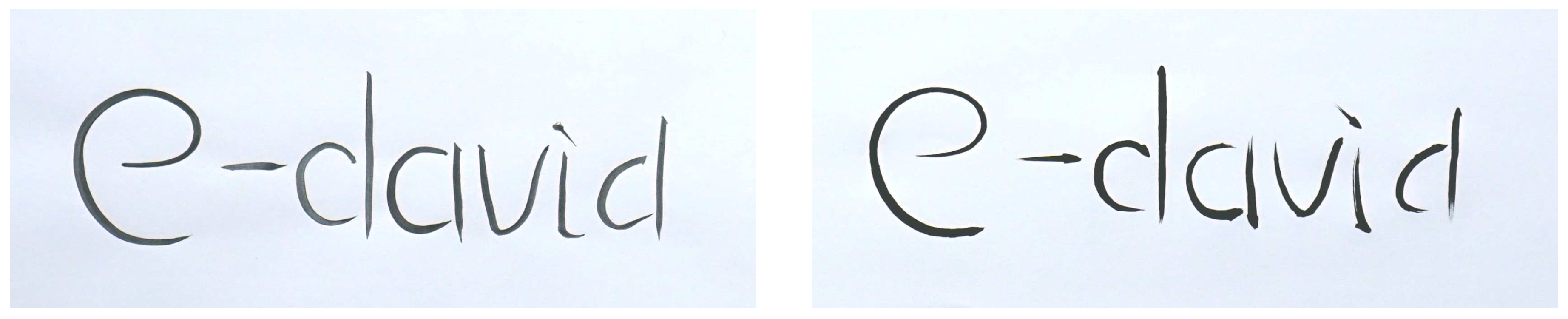
An application of stroke reproduction is copying human writing, as shown in
Figure 9. The example presented here was performed by the robot using only its optical systems. The prototype writing was photographed, each individual stroke was extracted and analyzed with the method described in
Section 4.4. Additionally, the distance between strokes was preserved. Then the robot was able to write the presented text on a separate sheet of paper. In principle every type of writing or sketch can be reproduced with this method, as long as no self-overlapping strokes are used.
5.2. Stroke Improvement Results
Figure 10 shows an example of this approach producing an improved stroke.
The improvement method has approximated the stroke almost perfectly after one improvement iteration:
Figure 10f is a difference image of the original stroke and the second attempt. Both strokes match very well in shape and size: the length is exactly the same and start and end points are located in the same position. The overall shape is also identical: the top loop, the long straight section and the bend at the bottom correspond precisely. Deviation can only be seen because of slight variations in stroke width. These occur since the width is not adapted between attempts, as this has proven to disturb trajectory approximation significantly. The general width profile is nevertheless still similar, as the middle part is thicker and width is smallest at the top loop. When comparing the original stroke and the improvement result without the difference image, both strokes are strikingly similar. Hence the method does successfully self-improve its painting technique.
All experiments have led to convergence between stroke prototype and the robot’s attempt: while this is not always guaranteed, as random defects in the brush or paint could cause disruption of previously achieved progress, significant errors have not been observed during experiments so far. In general, the robot manages to reduce the average distance between prototype and attempt control points by approximately 14 mm each iteration, which has been achieved consistently in ten different experiments with varying stroke prototypes. The stroke in
Figure 10a is about 110 mm tall for reference.
The main advantage of this approach is that no brush model is required to determine how to improve a stroke. The physical experiment is run with the real brush and the resulting stroke is used directly to infer an improved motion plan. As a consequence, the robot can adapt to any kind of disturbance, like a bent brush, unexpected paint behaviour, or other influencing factors. This saves a lot of effort in figuring out what parameters are relevant for the result and how they can be quantified.
The presented method has proven to work with all tested strokes: in every case improvement was observed over the initial reproduction attempt. Convergence was quickly achieved after a few attempts, because once a part of a stroke attempt matches the prototype well, that segment remains unchanged. Due to its simplicity, this model also provides a good baseline for future stroke improvement approaches.
Furthermore, as multiple experiments are run for every stroke, a lot of new strokes are gained for the stroke database. These are variations of the target stroke and can be used to analyse how a slight variation in motion changes the resulting stroke.
The main disadvantage of the experimental approach is that optimizing a stroke costs both time and material: as the robot moves slowly to avoid spilling paint, one optimization run takes at least one minute to complete and can take up to twenty. Hence time is still a major limiting factor for acquiring data about strokes. Furthermore, paper and paint are consumed and must be replenished, which as yet cannot be done automatically.
Another drawback is that only brush movement in the XY plane and pressure are considered as optimization parameters. Brush angle and twist are currently not accounted for. While most strokes can be approximated well enough using a brush being held perpendicular to the canvas, it could be necessary to include angle variation later on.
6. Discussion: Technical Implications
The feature we have developed that allows the robot to self-improve its strokes is a first step towards a painting process that can accumulate knowledge about the tools and materials being used. The inclusion of such mechanisms will allow the system to move away from the current static painting method and paves the way for more sophisticated paintings. The automatic improvement of a manufacturing process through observation of the results, as we have developed for e-David, might be transferable to industrial applications and make robots more suitable for new tasks. Current robots are able to detect internal failures
Visinsky et al. (
1994) or wear and tear
Trendafilova and Van Brussel (
2001) and some metal manufacturing machines can detect tool failure
Tansel et al. (
1995). These approaches all rely on motor sensor data, but in the case of tools which do not require much force to use, such a method might not be applicable. Hence visual checks of work progress can be useful.
Now that a simple method to improve strokes has been implemented, the generated data can be used in machine learning approaches. This can allow a learning system to predict brush dynamics by learning from past behaviour. Furthermore, a generalization to more complex brush movements or sequences of these can be developed in order to move from single-stroke painting to surface based approaches. Current learning approaches for style transfer
Gatys et al. (
2015) or artwork generation
Elgammal et al. (
2017) are pixel based. Moving from the pixel level to applying known discrete stroke or surface features could lead to improved results and mimic human works more closely. A prerequisite for this is to find a way to introduce the stored stroke data into such learning systems.
As a final note, because strokes were only handled as “solid” objects, methods that also consider how to develop a certain internal structure can be highly relevant as well. In conclusion, improving upon these details and including the techniques that create them into the painting process should make e-David paintings more detailed in the future.
7. Discussion of Artistic Implications: Human-Machine Interaction as a Neutral Base for a New Artistic and Creative Practice
In collaboration with computer engineers, neuroscientists and machine engineers, Grayver has been exploring new methods for the application of paint on canvas, as well as for computer-assisted generation of physical images, and has been using computers and machines in the service of exploring new aesthetic avenues in painting. This work aspires to constitute a novel venue for the establishment of new and innovative ground in contemporary artistic practices.
7.1. Artistic Motivation: The Importance of the Individual Brushstroke
The whole of artistic activity can be described as an instance of self-regulation. Order in painting is traditionally achieved through the self-regulation of the painter and by external intervention. It is necessary to distinguish between—and balance—those characteristics relevant to the realm of individual artistic perception and those that are external to the artist’s motives, intentions and preferences.
Generated data and robotic technologies are tools used in Grayver’s artistic practice to explore, retain and express visual information in relation to the digital and machine-based world we live in today. Her work with the e-David painting robot explores the different ways the body and mind perceive not only the visual objects themselves (such as painting), but also the process through which they are created—what is seen as a whole (form) and what is felt as energy (vector). Grayver states:
“During the working process, passive materials (canvas, paper, wood surfaces, etc.) react to my active manipulation of materials upon them; both the passive and active elements are equally and reciprocally important to the process as well as to the finished work. Using and mixing different media in one work creates a rich context in which I explore the tension between marks that are made with bodily gestures and those made with different degrees of technological intervention.”
Since 2015 Grayver has been exploring the general contemporary situation of painting and, more specifically, her own practice as a trained painter from a European art academy. She has dedicated herself to the exploration of the technological aspects of painting, returning to the elementary questions of painting, seeking to reflect on the relationship between image and objectness of the medium within the context of our technological era. Grayver states:
“My engagement with the technical conditions of creating images—digital as much as traditional print- and paint-based—has greatly influenced my conceptual understanding of the painterly process in historical and contemporary practices, and has ‘left a mark’ on the evolution of my own artistic activities. Stimulated by the experience and by the exchange between informatics and the robotic world, I found myself to some degree compelled to challenge and reconceptualise the foundations of my painterly practice, starting with the bodily movement of the single brushstroke all the way to questions concerning control and loss of control in the creative process.”
The practice of digital image-making represents a new manner by which images can be created whose sources are not derived from painting or photography, but rather arise through the writing of computer code, and are therefore not based on existing images of things. Such an approach makes it possible to deal with the cultural and psychological implications of our environment through symbols. This particular manner of creating images can of course encapsulate a huge amount of information, emanating from the most diverse sources—for example, fractal models from nature, physical phenomena and mathematical laws—that can then be translated into the visual domain. However, despite the widespread prevalence of digital image-making today, hardly any research has been conducted into the practice of translating images created via a computer simulation into the physical world using brushstrokes.
7.2. Artistic Collaboration
Since February 2016, Grayver has been collaborating with the e-David Project on the use of robotics as a painterly tool that can assist in the exploration and development of new creative and aesthetic approaches, and even in shaping our understanding of painting. The following describes her use of the robot in her private practice and interpretation of robotic arts. In this collaboration, the robot is used as a painting tool due to its nonhuman capabilities, such as very precise repetition of movements.
The focus of the collaboration has grown from more deterministic approaches of machine-based painting to dealing with contemporary questions regarding artificial intelligence (AI) and machine deep learning, and their use in the artistic domain. The interdisciplinary working platform between computer scientists and an artist can provoke a large range of questions regarding the use of robotics in the creative process of painting: How does one incorporate the use of computers and machines in the very intuitive and gestural practice of making a painting? How would we decompose the act of making a mark to a body movement (machine), taking logical decisions (computer) and emotional intentions (the artist)? Subsequently, Grayver established with the e-David team an official plan of collaboration in order to investigate human creativity through the interactive methods of computer-to-machine (simulated to real) and man-to-machine (artist working together with the machine) methodologies.
7.2.1. Composing a Painting from Individual Strokes
When Grayver first witnessed the e-David at work during a preliminary visit in January–February 2016, she was fascinated by the paths the robot chose to distribute strokes on the sheet once it began to structure a painting. To a trained painter like Greyver, the robot’s stroke placement initially seemed to be illogical, strange, even arbitrary. But, it sparked a curiosity to understand the logic behind it, and illuminated an idea that the nonhuman attributes of robotic painting could cause us to rethink the practice of painting. In other words, to paint in a way that no painter would ever consider; to engage with decisions about forming and deconstructing an image; and to instigate and explore new approaches to structuring task order in the working process.
Through the collaboration, Grayver and the e-David team explored further possibilities to exploit the painting robot creatively and reflected on ideas about the ways in which these could be implemented in the form of software and hardware. A number of questions of wider impact arose as the result of the collaboration: When and why would a semantic method of defining the object in the image be used? Is it an advantage or a disadvantage to paint semantic objects without having a pre-existing cognitive understanding of them? How could we use abstract forms, grammatical structures or mathematical models to achieve more complex surfaces? How would computer language be used to express the intentions of a composition? When and why would different painting styles be used? Further, on a technical level, we had to take into consideration how different materials would react to one another. For example, how could different colours be mixed on the canvas or on the palette? How should the size of the brush be set, and when is it necessary to add glaze? We would have to develop a range of distinct, individual brushstrokes (controlling the velocity and the z-axis) whose characteristics are analogous to those made by human painters in the “real world”, in order to be able to pre-define when, in which order and for which tasks each stroke is to be used. In doing so, we are basically defining and categorising singular parameters within a library of painterly “acts” and “perceptions”, in order to create a grammatical structure for the “language” of robotic painting.
All of these questions—qualitative technical aspects, creative and aesthetic value, etc.—would need to be defined by the team and saved in the visual feedback of the robot as parameters or as rules. This led us to questions of control: To what degree should the robot’s actions be controllable by humans? Should the robot make autonomous decisions? If so, at what stage? How would we evaluate the output of the robot (with such binary values as good/bad, or yes/no?). And how would these evaluations be saved to its memory such that the e-David would be capable of using this information “correctly”, in turn enabling it to make new decisions about its actions in the next run?
7.2.2. Making Abstract Painting: Thinking in Vectors Instead of Pixels
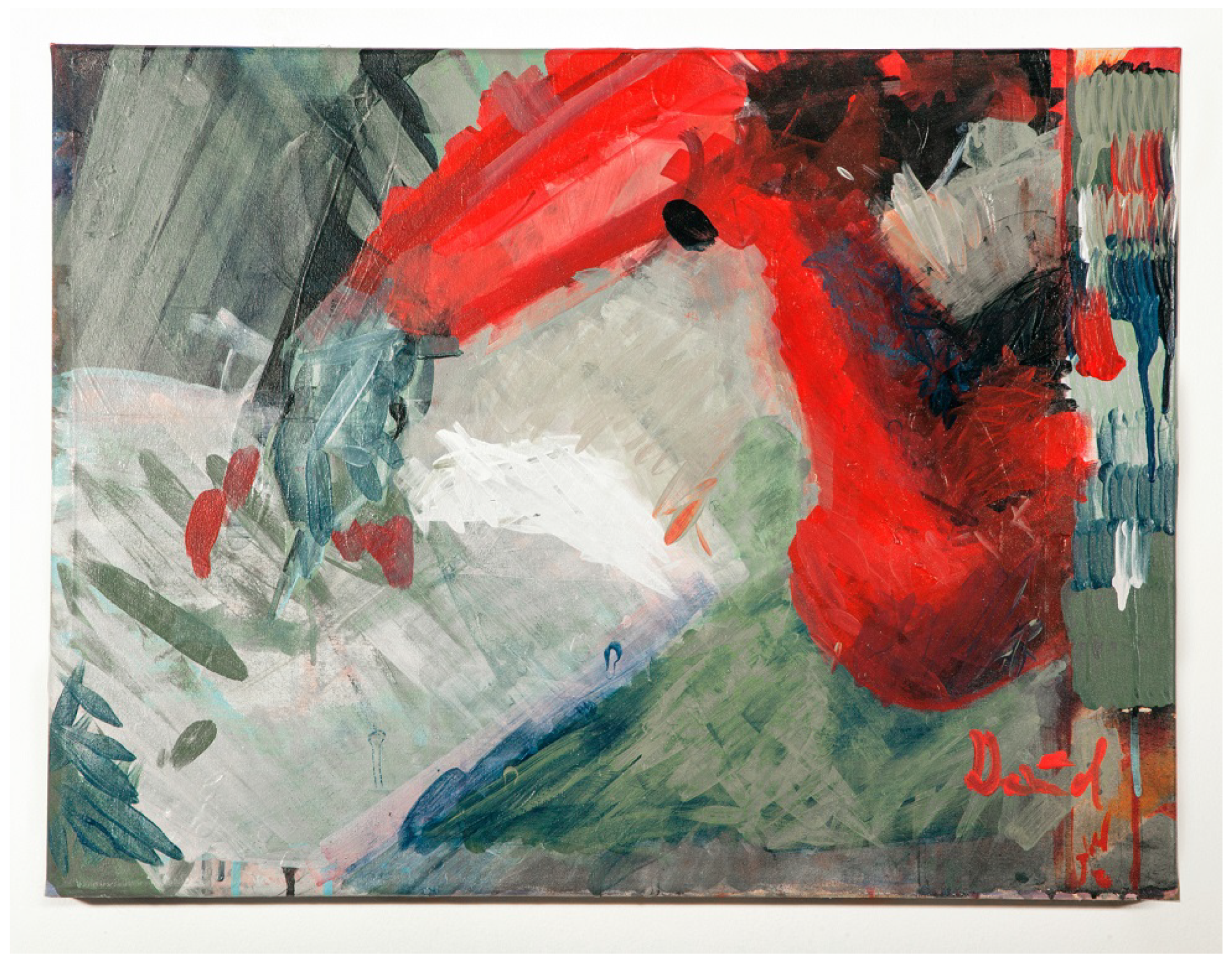
The paintings series “Just Before it Snaps” (Liat Grayver and the e-David) is an investigation into abstract thought and experimentation with composition as energy fields that were configurations of vectors (Rudolph Arnheim’s study on composition in the visual arts). Grayver was looking for the places or “border areas” in which the balance between coincidental and intentional brushstrokes created harmony on the visual surface.
From another point of view, these images were a stage for experimenting with the different painting materials used in the robot lab. Typically in human painting, the materials are controlled by the painter in a sort of interactive “ping-pong” situation. With the e-David robot, however, this is not the case as all of its actions must be predetermined and given as commands. The robot does not, for example, notice if the paint is dripping or has dried. It is exactly these limitations that are fascinating from an artistic point of view, as it stands in opposition to “normal” thinking and allows for the emergence of new, uncontrolled and surprising brushstrokes.
7.2.3. Grouping Singular Lines into Forms Using Nodes and Centre Points
In the early abstract works done with the e-David in June 2016 (“Just Before it Snaps”, see
Appendix A,
Figure A1) individual painting operations were programmed such that the entire surface of the painting was treated equally (overall composition). Singular lines were used to construct the paintings, with each new line created according to given (programmed) variables. The first line was positioned according to a pre-determined starting point, and the location of each subsequent generated line was calculated in relation to the line painted before it. We had introduced into the system a strategy of dividing the painting into masks of colour areas using brushstroke patterns—sets of individual brushstrokes—in contrast to an approach using singular strokes. Masks were applied to fill in a section one colour at a time, according to pre-defined light and shade characteristics. In this series of paintings, the computer generates a set of strokes that are connected or related to each other due to their proximity of action, corresponding to the painter’s bodily movement when performing similar tasks.
For the next step, we created a new set of paintings “Resisting Gravity” (Liat Grayver and e-David,
Figure A2), using limited sets of zigzag and straight lines, as well as a grid pattern formed by intersecting brushstrokes. In order to give the patterns an organic and complex surface feel, and to break the precision and mechanical appearance of the repetitions, we defined the specific character for each set according to the following parameters: orientation of the set, curvature of individual lines within the set, centre point of the painted masks, angle of the meeting point of the two lines, number of strokes, and proximity between lines—all of which are subject to a degree of randomness.
This grouping of lines into blocks of paint enabled Grayver to incorporate the concept of a centre point as a parameter for the computer when generating a painting. This way, the brushstroke patterns are generated to be located either around or emanating from a pre-defined position.
In order to avoid the creation of a closed composition with poor visual tension, Grayver defined several centre points in a single painting. By experimenting with different colours and brushstroke characteristics (settings), the centre points can be made to support each other as visual nodes in the painting composition.
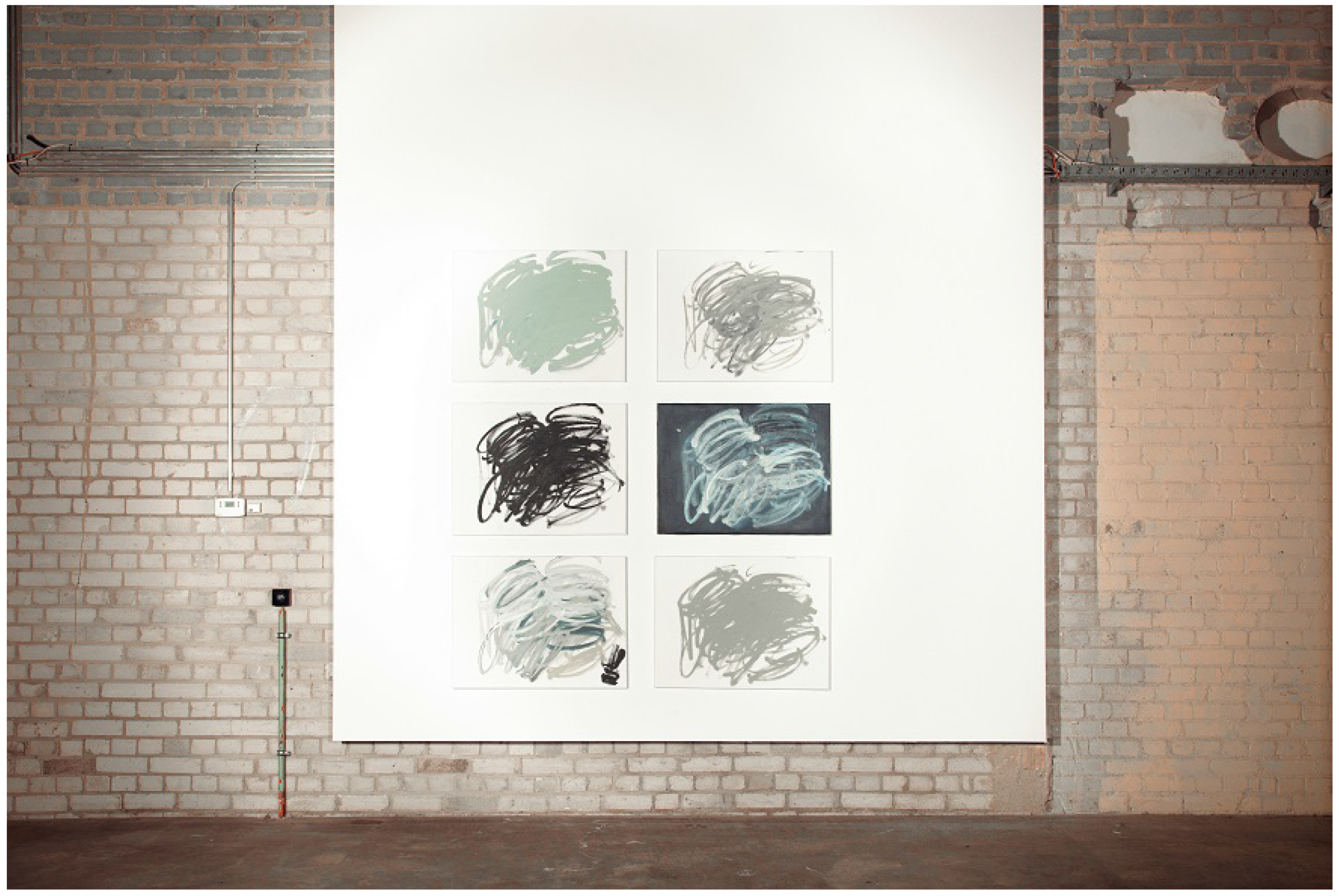
“Six Variations on Gestural Computer-Generated Brushstrokes” (Liat Grayver and the e-David,
Figure A4), done in October–November 2016, is a series of computer-generated sets of brushstrokes that reflect the quality of spontaneous hand movement inspired by the practice of Japanese calligraphy. Using the e-David, Grayver repainted the same generated path again and again, each time on a new canvas, knowing that this kind of exact repetition of movement could never be achieved by a human hand. Each of the variations is an execution of the same path with an identical velocity. Nevertheless, the works are varied and can be distinguished from one other due to the use of different brushes and changes in the value of the colour, as well as variations in the viscosity of the paint and the number of times the robot was instructed to load the brush with new paint. Some of the variation applied the repetition using a layering method. Sometimes the paint didn’t have enough time to dry, and so instead of the brush applying a new layer of paint, it actually scraped some of the paint off the canvas, creating some surprising and pleasing surface effects. To distinguish the layers from each other and to give the painting some visual depth, Grayver applied different painting techniques (glaze, colour variation, viscosity variation) and juggled with the information saved on the computer—for example, stopping the robot and restarting it at different points in the process or breaking and reassembling the loop action into fragments.
7.2.4. Perception of Brushstrokes Made by an Unconscious Body
Painting is a practice in which a complex architecture is constructed of separate sections that interact with each other as a whole in the form of a unified composition. While working on the e-David “Self-Portrait” (
Figure A3), Grayver became aware of the need to divide the painterly process into different categories, looking into the different paths of the physical act (characteristics of individual brushstrokes) and cognitive decisions (semantic vs. abstract recognition of geometric forms) that the painter uses in the process of decomposing and reassembling visual information and material elements into a painting. More than that, the ability to save each step in the painting process and to compartmentalise and conglomerate information and action in different constellations, opens up a new field in the painting domain that explores the space between abstract and figurative painting. Grayver states:
“Saving information in the painting process and creating, when needed, a distance between the painter and the painting (the painter is simultaneously the viewer and the executer) are two features that computer- and robotic-based painting offers the artist. As a painter and a consumer of art I wondered if I would be able to recognise brushstrokes done by a robot in a more complex, generated work. I wanted to play with this idea by generating strokes that appear gestural but are executed in a way that only a machine is capable of doing, namely, with exact repetition.”
7.2.5. Traversing the Threshold of Materiality
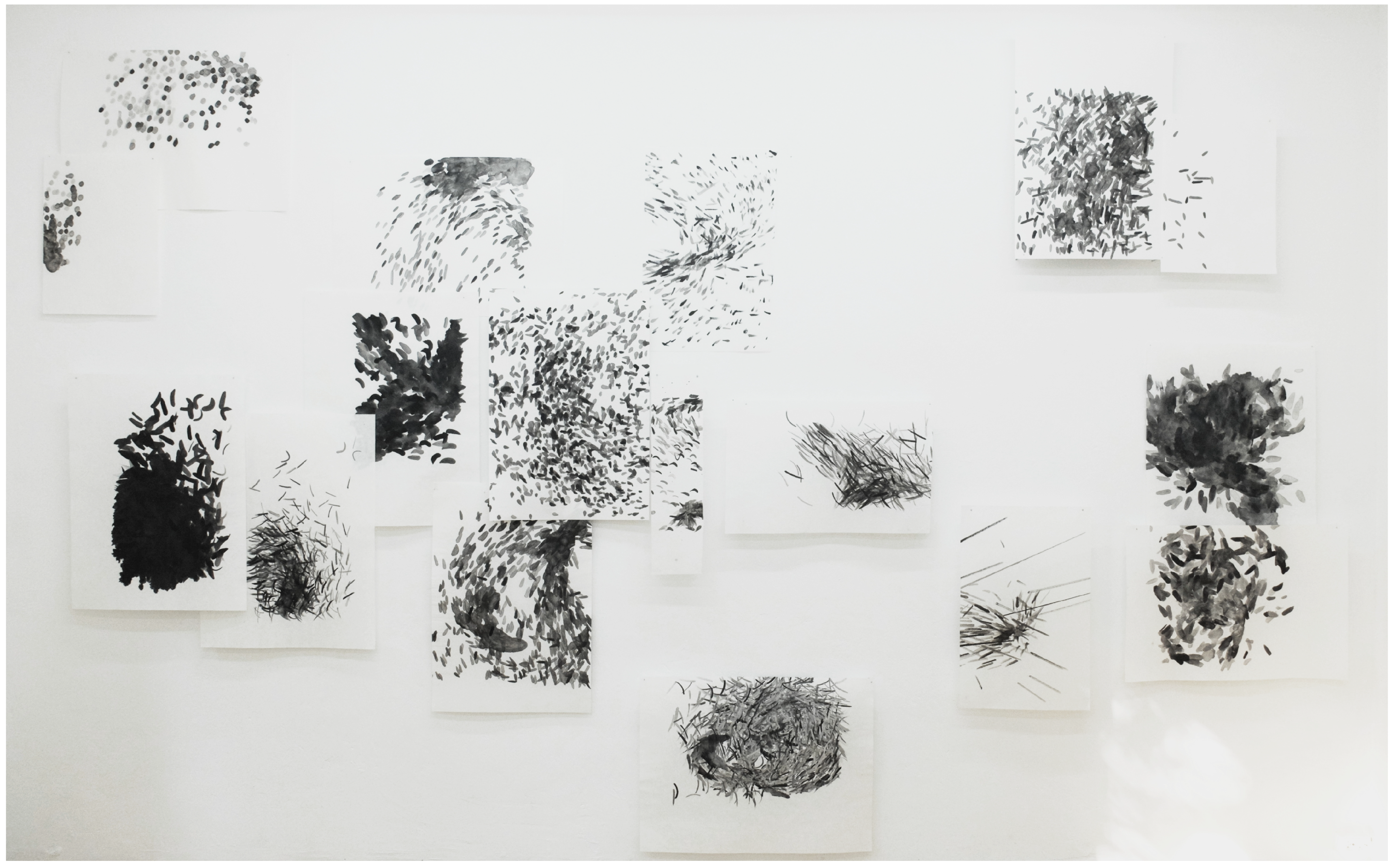
The work “Traversing the Threshold” (see
Figure A5) features a room installation of robotics-assisted calligraphic works that stretch into and expose the temporal and physical space of the artist’s creative process through the mediums of robotic painting. What could have been executed as one painting constructed of thousands of brushstrokes has instead been decomposed and distributed over numerous sheets of rice paper.
The individual paper works are extracted from a complex of computer-generated particles (Simulation of a World Overview) according to Newton’s Law of Gravitation. Scaled to different sizes, each can be viewed not only as an individual work but also as part of the modular wall installation. In the creation process, Grayver cropped different sections of the master particle generator and translated the individual particles into single brushstrokes (assigning parameters such as, for example, the size, length, pressure and speed variation of the strokes), before sending it to the e-David robot for the final execution.
The fragility of the ink-infused rice paper work in particular stands in sharp contrast to the industrial robot used to create them. As with Japanese calligraphy, the brush trajectories and the ink’s behaviour as it penetrates the surface are of far greater importance than the perception of the object itself.
8. Conclusions
The e-David project is currently a rare fusion of technology and art. The original design goal of robots, namely to perform repetitive tasks at high speed, present limitations which we seek to circumvent through the new methods developed for e-David. Our novel techniques of brush calibration and self-improvement integrate tools that are imprecise by their nature into the framework of robotic precision. This allows e-David to be used as more than just a remote controlled brush and provides a base from which painting technique can be understood and automised.
A focus on single brushstrokes, or the painting of small features in general, allow the artists working with e-David to operate on a much higher level, and to forgo very low-level programming of the machine. The brushstroke, in its various manifestations, is the singular tool of communication that is encountered in paintings and drawings throughout all epochs. Our driving motivation in this cross-disciplinary artistic research is to study painting from the perspective of its most essential act, i.e., the process of making of a line as opposed to the study of the painting itself (the artistic object). Hence we have placed a special focus on single brushstrokes in our research.
E-David’s new capabilities in the domain of painting technique and the collaboration with artists are moving the entire project closer towards producing both a robotic painter and a mechanised assistant for the human artist.
Future Work
For the future development of the project we envison three main areas of research:
We have established single strokes as primitves for the painting process so far. In next iterations of the software we will recombine these in certain patterns to fill surfaces with different structures. This will transfer yet more control of the painting process to the robot, thereby impacting the artwork created and how artists can use the machine.
The stroke experimentation creates a dataset of robot movements and the associated stroke. We will extend this dataset by enriching it with more information and by letting the robot collect new strokes for long periods of time. We will also explore how the robot can more efficiently perform its own experiments to streamline data acquisition.
The collected stroke data will form a basis for using machine learning (ML) techniques in the future. While the usefulness of ML for e-David must be evaluated closely, some promising and applicable approaches exist: Gordon et al. have developed a method that allows a learning agent to explore those aspects of a task it has very little knowledge about
Gordon and Ahissar (
2011,
2012). This is a natural extension of the experimentation with strokes conducted in this study, and will allow the robot to make more directed trials.
9. Additional Information: Detailed Technical Description of the Painting Setup
The current painting setup and operating principle of all e-David machines was originally designed and built by Deussen and Lindemeier, who initiated the project in 2008
Deussen et al. (
2012),
Lindemeier et al. (
2013). The description given here contains both their previous development efforts and recent additions to it.
9.1. Painting Setup
The schematic layout of an e-David painting machine is shown in
Figure 11. We place a robotic arm in front of a canvas, which acts as the workpiece. The canvas is angled such that singularities are avoided and that the working envelope of the machine is used optimally. The tool used by the robot is a brush of known length. The TCP of the robot is calibrated to lie exactly at the tip of the brush. The feedback camera is placed such that it has a full view of the canvas. Due to the placement of the robot between camera and canvas, it is necessary for the arm to move aside when a feedback photo is taken. We also set up a table for painting accessories next to the arm, where paints, exchangeable tools and a brush washing device are located. The washing device provides a water jet in which the robot holds the brush hairs to clean them before picking up a new paint which avoids cross-contamination.
Paints are held in small steel containers, which also provide an edge for the robot to wipe off excess paint. Currently there are no sensors to supervise the amount of paint remaining, but the 30 mL containers are usually sufficient for painting overnight. Paints are premixed by the operators and refreshed regularly.
The painting surface is mounted on a steel frame, which in turn is bolted to the robot’s base plate. This ensures rigidity and avoids the need for frequent recalibration of the workpiece location. While the machine never applies significant force to the surface, humans tend lean on it while inspecting progress or cleaning. Previous wooden frames would move too much and even slight deviations would cause inconsistent stroke widths to appear.
9.2. Robots
We use six-axis industrial robots for e-David, as these provide a large degree flexibility in their use. XY-plotters have also been considered, but much more hardware effort is required to implement all necessary motions with such a machine. For example, the robotic arm is able to wipe its brush on the paint container after dipping the brush in it, in order to avoid dripping paint. This is a complex motion which has the brush follow a trajectory through dozens of points at varying tool orientations and velocities. An equivalent XY-plotter would require at least five axes to be able to perform such a motion. Furthermore, the robotic arms are a mature technology, widely used in the industry, allowing us to use common design patterns in our setup. The machines provide very good accuracy (±0.01 mm) and are very reliable.
Two robots are currently in use: The Reis RV-20 6 is a welding robot, with a range of 2800 mm and weight of 875 kg
Reis (
2012). It is a traditional manufacturing robot, being suitable for the production of cars or similarly sized objects. This allows the machine to work on large paintings, but makes the device unsuitable for being transported to exhibitions.
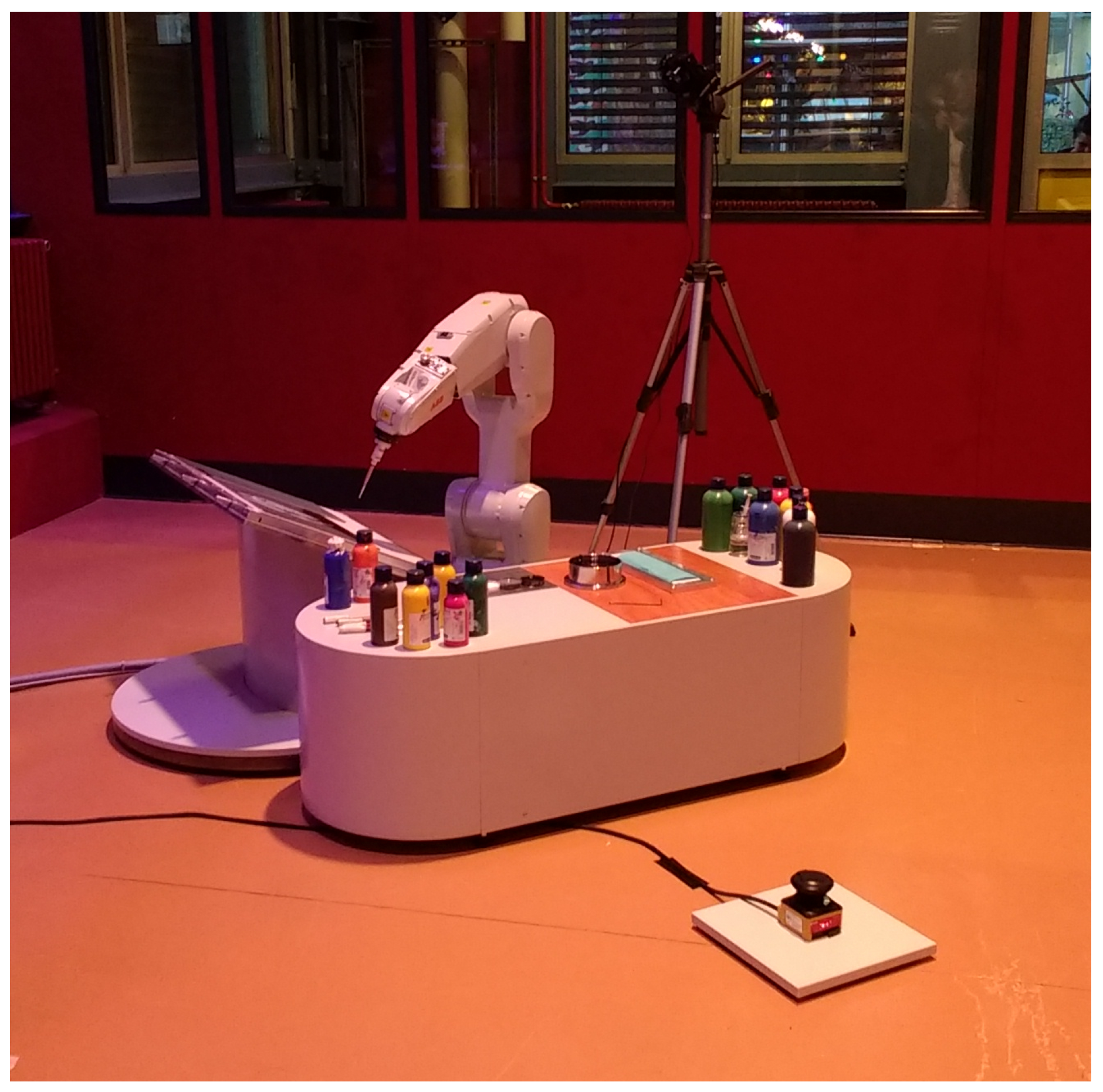
The ABB IRB 1200 is a general-purpose robot with an emphasis on a small form-factor and high speed operation. Unlike classical industrial robots, it is also suitable for medical applications or food processing. We bought this device due to its comparatively low weight of only 54 kg, as this makes moving it easy, given the right equipment
ABB (
2017b). The robot is attached to a 200 kg steel plate, which can be split into four pieces for transport.
Figure 12 shows the robot being exhibited in Zürich.
Both machines need to be programmed in a manufacturer-specific programming language, which is RobotSTAR for the RV-20 and RAPID for the IRB 1200. We implement a network communication interface, which allows both machines to receive commands from a control computer.
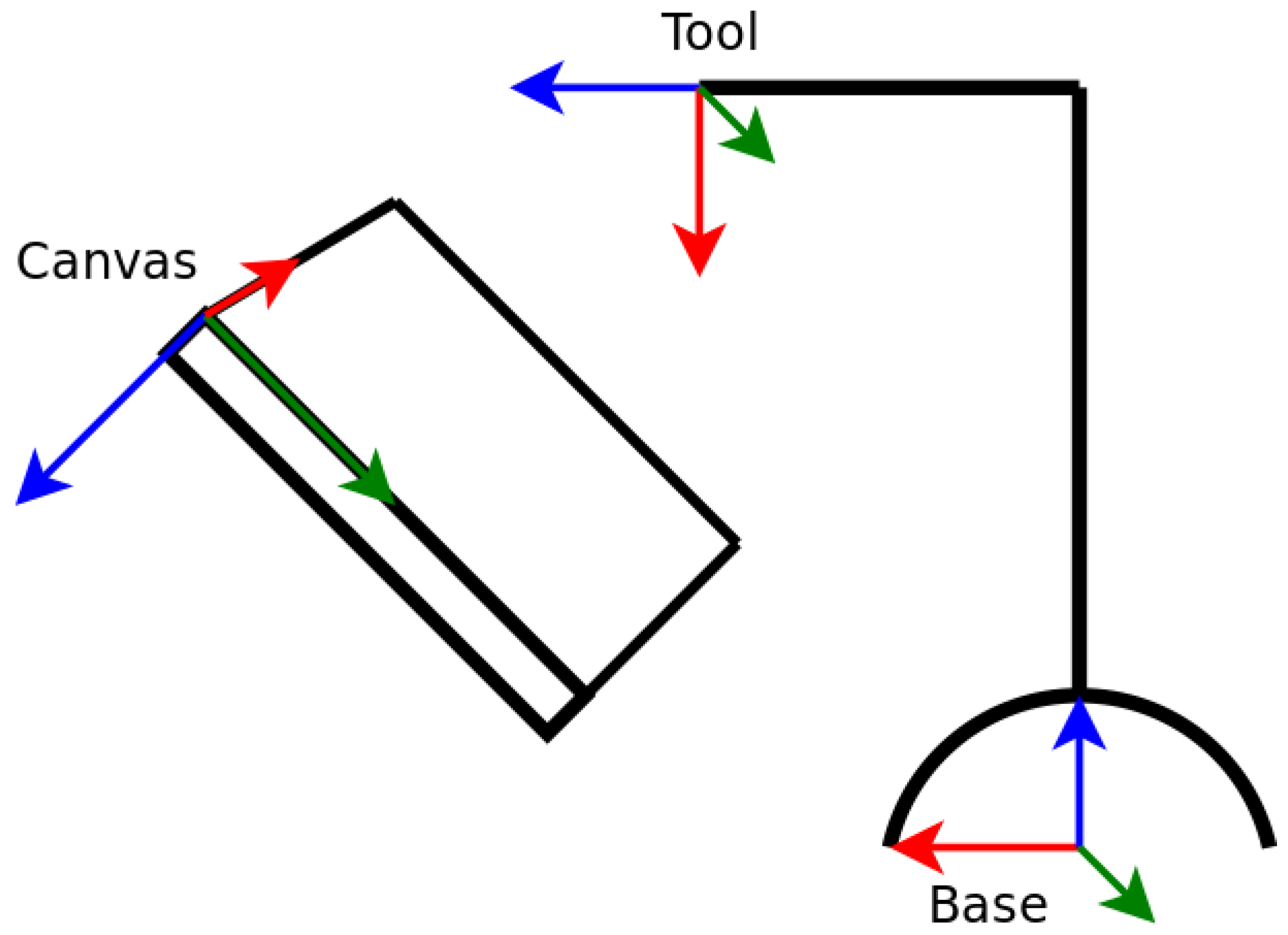
The robot uses four coordinate systems internally: The
base coordinate system has an origin located at the lowest point in the centre of the robots base. The
world coordinate system serves as the basic reference point for all other coordinate systems. It can be used to define a robot working cell but in this case its origin point is set to coincide with the base coordinate system. The
tool coordinate system has its origin point in the current tool centre point, or TCP. It defines the tool’s orientation and can be used for moving a tool with constant orientation. The
work object coordinate system defines the location and orientation of a work object onto which the tool is being applied. In the case of a painting robot, this is the canvas. Hence if the work object coordinate system is defined to be in a corner of the canvas, it is possible to reference points on the canvas by their XY-coordinate in the corresponding work object coordinate system
ABB (
2017a). Thanks to this mechanism, the painting software can use canvas coordinates which are easily transferable to the robot. An overview of all systems can be seen in
Figure 13.
The canvas coordinate system originates in the top left corner of the canvas. The X and Y axes lie in the image plane, with the X axis being the horizontal axis. The Z axis is perpendicular to the image plane. Z is zero on the canvas surface and is positive behind the canvas. The Z axis points away from the robot and is used to control the brush application pressure. A Z value of zero causes the brush tip to barely touch the canvas and increasing Z increases the application pressure. We limit Z for each brush to a known maximum pressure to avoid inadvertently breaking the tool.
A note must be made that neither the Reis nor the ABB robot can be used collaboratively with humans. Both machines can operate at high velocities and can produce a dangerous amount of force. They cannot detect a collision with a human and are thus unable to limit forces upon a body part which is in their path. Hence the robots are kept behind light barriers which exclude humans from their working range while they operate in automatic mode. In manual mode, their speed is limited and the operator must use a dead man’s switch when moving them. New collaborative robots are not planned to be included in the project, as they are expensive and there are no safety certifications for pointy tools such as brushes as of now.
9.3. Optical Feedback System
High quality DSLRs are used by the e-David system in order to acquire information about the canvas. Currently a Canon EOS 70D with a 20 Megapixel sensor and a Sony Alpha 6300 with a 24 Megapixel sensor are included in the setup. We use gphoto2 to transfer the images via an USB connection to the control computer. Transfer and analysis of a photo for feedback purposes can take up to a minute. However, since this time period allows the paint to dry, there is currently no need to optimize in this area.


