1. Introduction
Facades have always played significant roles in buildings, such as protector (as a barrier, filter, insulation) and/or regulator (by controlling, responding, changing) between outside and inside conditions [
1]. In recent years, in parallel with technological developments and rising awareness, the importance and attention given to building facade performance have increased. Facade performance is a general expression that involves various aspects such as functional, ecological, and economical. Even the functional performance of a facade has different aspects. Some of the functional requirements attributed to a facade are related to safety such as structural stability and fire protection, while some are related to health such as weather protection (protection against wind-driven rainwater, moisture, and air penetration), and others are related to the well-being of the users such as thermal, visual, and acoustic comfort.
Performance is contextual rather than an inherent property of a product or system [
2]. A decision maker has the ability to enhance the performance of a facade by making proper decisions on the design parameters in line with the conditions. Nevertheless, since facade performance has various aspects (sometimes conflicting) to be considered at once, it is hard to predict the impacts of decisions on the performance. A single design decision may increase the performance in one aspect while decreasing it in other aspects.
All aspects of facade performance must be taken into account holistically since the facade functions and is experienced as a whole. However, in the literature, there is a lack of a holistic point of view regarding facade performance. A considerable number of research studies and publications address a single performance aspect individually, or a few aspects separately from the entire facade performance.
Şentop et al. [
3] propose a catalogue to be used for noise control of exterior walls, while Şener Yılmaz [
4] has a proposal for a facade design approach which considers daylighting performance. Erdemir Kocagil and Koçlar Oral [
5] examine the effect of building envelope and form on cooling performance in a hot-dry climate zone. Şahinoğlu [
6] evaluates the effect of shading elements on the thermal and visual performances of the window. Another study deals with the impact of a glazing area on visual and acoustic comfort [
7]. Koçlar Oral et al. [
8] focus on ensuring thermal, visual, and acoustic comfort, while Sözer [
9] concentrates on energy efficiency in building envelope design.
On the other hand, some studies propose decision support models to be used in the design process. Ramachandran [
10] develops an integrated computational tool to support the building envelope design process. It is one of the studies in the literature that has a relatively holistic approach, although it excludes some relevant issues and leaves them to further studies. Arroyo [
11] explores and compares multi-criteria decision-making methods for sustainable design in commercial buildings. Güzelçoban Mayuk [
12] proposes a fuzzy method to be used in the facade design process. A relatively older study has an approach to building envelope design with a knowledge-based system [
13]. Most of these decision support models are developed and proposed to be used in the early design stages. Donato et al. [
14] develops an innovative app, Arup Solar, for a parametric, holistic, and multidisciplinary approach to early design stages. The app aims at investigating the relationships between envelope features and cooling strategies. Schmid and Marinitsch [
15] address design methods and facade technologies for advanced building skin design.
Moreover, there are a substantial number of research studies focusing on optimization in facade design. Gagne and Andersen [
16] use a genetic algorithm to optimize the facade design for daylighting performance. Zemella and Faraguna [
17] also use genetic algorithms in order to optimize the energy and space performances of facades. In that study, they search for the optimum facade design considering both the engineering and architectural issues. However, it is also based on some assumptions, and the proposed methodology is validated and implemented with a limited number of design variables. Another study [
18] tries to optimize the configuration of a facade module for office buildings from an energy perspective (thermal and lighting). Bilow [
19] deals with the optimization of facades from a climatic point of view. Glassman and Reinhart [
20] optimize facade using parametric design and future climate scenarios. Jin [
21] develops an optimization model to identify facades achieving optimal indoor environmental quality with the lowest cost and the shortest carbon payback periods.
Today’s technological developments enable facade performance evaluation via simulation tools or field studies in real conditions. Energy Plus, Comfen, Radiance, Window, and Therm are a few of the simulation software. However, there is not a single tool that is able to simulate all performance aspects, and it is not feasible and economically logical to test all design alternatives in real conditions. Besides, design is a process with several variables that need to be counted simultaneously.
From this point, we discuss a tool developed to function as a guide to decision makers by indicating the impacts of design decisions on separate functional aspects of facade performance from a holistic point of view. Thus, the decision maker is aware of the consequences of the decisions and has the opportunity to make proper trade-offs in facade design.
In the early stages of building and facade design, where many design alternatives must be considered in a limited time period, a tool that enables decision makers to gain a holistic perspective of facade design results in roughly correct design alternatives to be evaluated in further design stages.
All the above-mentioned examples of research papers are valuable for the discussions they initiate and their findings. We believed that a tool could be structured by organizing the existing information and knowledge in the literature. It could provide holistic support in the early stages of facade design by using the outcomes of various research studies conducted by different disciplines with different points of view and by establishing the relationships between aspects to constitute a meaningful whole.
Instead of testing and evaluating a large number of alternatives via simulation tools or field studies in real conditions, we believed that a process that followed a model with a holistic point of view and that reduced the number of design alternatives in the early stages of design process to a lesser amount and near-ideal options, thereafter allowing an evaluation to be carried out accordingly, could have a significant contribution to the facade design process.
This paper presents a holistic decision support tool developed for use during the early stages of facade design. The tool bases itself on the interdependent relationships between facade performance, facade parameters, and conditions (environmental and spatial).
2. Methodology
Basically, the research is presented in two parts—formation of the tool and testing of the tool. First, the literature was reviewed to understand the nature and dynamics of facade design and the aspects of facade performance. Then, after an in-depth analysis of the literature, relationships were established between facade design and facade performance, facade performance and conditions, and conditions and facade design. Existing research results were compiled to make generalizations for the interrelations between design decisions (facade parameters) and facade performance aspects in conjunction with outdoor and indoor conditions. After specifying affecting agents and performance indicators and metrics for each performance aspect, we used these to analyze, filter, and resolve the information and knowledge available in the literature. Then, since the ultimate aim was to develop a tool with a holistic approach, a framework was drawn to gather all separate aspects into one platform. The designated relationships are presented in matrices.
Decision-making is, in one sense, a selection process where decision makers must decide on an option (select an option) among several others. They must make comparisons while considering various aspects. This is the inherent nature of decision-making. Therefore, a comparison-based assessment methodology was preferred for the tool. Moreover, a simple rating scale (+, −, 0) was adopted to be able to evaluate all aspects in one equation. This method allows for the assessment of design in terms of separate performance aspects regardless of their specific metrics.
The tool is designed to rate the options based on “if-then” and “unless-then” relationships (conditions–functions) derived from the literature. For example, a research study in the literature indicates that acoustic performance of a facade glazing (sound insulation against outdoor noise) can be improved by one of the following design strategies: increasing the mass (number and/or thickness of glass layers), increasing the gap between the glass layers, filling the gap with heavy gases, and undertaking the asymmetric assembly of glass layers. Assuming what precedes, one can conclude that the more the layers, or the greater the thickness, or the thicker the gap, or the heavier the gas, or the more the difference in layer thickness, the better the acoustic performance. Options are rated gradually in line with this design–performance relationship. Advantageous and disadvantageous options are given (+) and (−), respectively, whereas mediocre ones obtain (0). To run the rating function, the first condition of the tool is the availability of traffic noise. If there is traffic noise, then the tool gives some options (+), some (−), and some (0).
In some cases, the difference among the options has more critical effects on the performance, as follows: if the transparency ratio is higher (≥50%) or if the facade is in the direction of the noise source or if the space is highly noise-sensitive such as in patient rooms, then the previous ratings for the glazing options are multiplied by (2) as to become (+ +), (− −), and (0). These are the assumptions of the tool in order to provide a rough but holistic impression about facade performance in the early stages of facade design. Conversely, if there is no traffic noise, options are not rated by the tool and are given NA (Not Assessed). Other types of noise sources such as construction, entertainment, people, etc., are not considered within the scope of the tool.
In the meantime, the relationship between each facade parameter and each performance aspect is weighted for a holistic evaluation, because not every parameter affects the performance with the same strength. Weighting the relationships is considered as one of the systematic design approaches [
22]. The tool considers three types of relationships, namely, strong, medium-strength, and weak, and 5, 3, and 1 are the numbers assigned to weight these relationships. Again, a simple scale is adopted to keep the calculations relatively simple, and the results comprehensible.
The strength of relationships is determined in two ways. First, assumptions are made based on the literature. Second, the assumptions are crosschecked with experts and refined. At least one expert for each performance aspect was interviewed.
Finally, the tool gives a score to each option (of each decision subject) for each performance aspect. The score is the product of rating and weighting. Then, the scores given for all decision subjects are accumulated for each performance aspect individually (see the equation below). It is assumed that the sum total of the design decisions composes the facade design.
Final score of individual performance aspect =∑ design decision scores (rating × weighting).
Since it is a comparison-based decision support tool, it is preferred to present the final evaluation graphically. The overall facade performance is illustrated by a spiderweb graphic which has separate sections for each performance. The graphic helps to make comparisons in a holistic way. Neither the tool nor the graphic gives the real performance values, but rather (which we conclude is better) gives the impression for the overall facade performance, which is believed to be more comprehensible for decision makers regarding facade design.
3. Research
3.1. Formation of the Tool
Performance aspects included in the tool are structural, fire, water-related, air permeability-related, thermal, moisture-related, daylighting, and acoustic performances. These correspond to functional performance aspects [
1,
21,
23,
24,
25,
26]. Facade parameters defined as the main decision subjects within the tool are orientation, transparency ratio, facade type, window type, glazing, wall configuration, and shading.
3.2. Generation of Design Options
First, for each facade parameter (decision subject), design options are generated in accordance with the existing facade industry and knowledge. The options are not for limiting the flexibility in design; they are for keeping the tool relatively simple and comprehensible, and for guiding the tool users (decision makers) to make deductions for their specific options. The options are chosen among the systems, components, and materials widely used in today’s construction industry, which cover the performance-improving strategies within the tool.
Options for orientation are the cardinal and the intercardinal directions: north, south, east, west, northeast, northwest, southeast, and southwest. Side-lit spaces having a facade on one side are included in the tool, so the orientation indicates the direction of that facade. Transparency ratio options are 0%, 25%, 50%, 75%, and 100%. Facade type options are generated considering the categories of reference books [
1,
25,
27,
28,
29,
30,
31,
32,
33,
34] for facade systems. Non-self-supporting facades are considered within the scope since they constitute a great majority of today’s designs. The options are combinations of the number of skin types (single-skin, double-skin) and construction types (infill, cladding). The second-skin type of double-skin facades is included in the tool. Box-window, corridor, or shaft-box types are kept out of the scope. Masonry, frame, monolithic, and window are adopted as types of infill construction. Light-weight curtain walls (here considered as curtain walls) and heavy-weight curtain walls (concrete claddings) are taken as types of cladding construction. Options for window type are combinations of window position in height (vision level, upper level, full-height) and depth (flush, recessed) and window operability (operable, fixed). Number and thickness of glass panes (single, double, triple in various thicknesses), gap thickness and type of infill gas (air, krypton), color/coating of glass panes (clear, green-tinted, low-e coated), and assembly of glass panes (symmetric or asymmetric) are the variables in glazing options. Wall configuration options are generated by considering the permeability of the cladding (impermeable, semi-permeable) and the presence of an air cavity (available, none), position (outer, middle, inner), and type of thermal insulation (rockwool, extruded polystyrene, expanded polystyrene). Shading options are generated in consideration of the following parameters: availability (available, none), direction (horizontal, vertical, both), and type (overhang, light shelf, louver). The tool also provides written and visual information describing the options for the users. Since the tool is aimed to be used in the early stages of the facade design process, it is not preferred to define the possible options with numerical values.
The tool is composed of five major sections: input page, tool process pages, output and decision-making pages, and evaluation page. The working principle of the tool is given below (
Figure 1).
3.3. Input Page
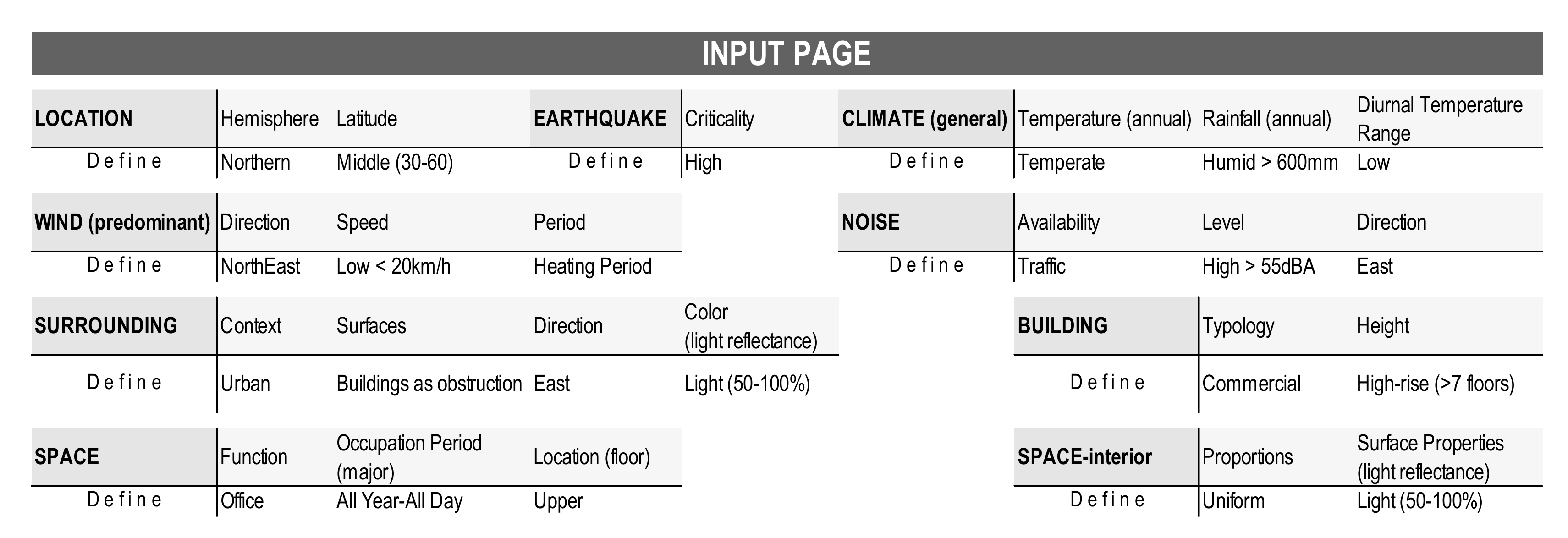
Use of the tool starts with an input page where the tool user is asked to define environmental and spatial conditions from the drop-down list. Location (hemisphere, latitude), earthquake (criticality), climate (annual temperature, annual rainfall, diurnal temperature variations), predominant wind (availability, direction, speed, period), noise (availability, type, direction, level), surrounding (context, availability and direction of obstructions, surface light reflectance), building (typology, height), space (function, occupation period, floor location), and space interior (proportions, surface light reflectance) are the issues to be defined. Northern and Southern Hemispheres have completely different criteria in terms of daylighting and thermal performances. It is preferred to keep the first version of the tool simpler, so the rating algorithms are designed just for the Northern Hemisphere. Similarly, road traffic noise, being a very common noise source, is taken as the only type of noise source within the tool. The input page is given in
Figure 2.
3.4. Tool Process
As the tool user defines the conditions in the input page, the tool process starts to run, and first gives the rating results for the orientation in the output page. The options are rated by the tool based on the conditional functions defined in the tool process. They are based on the references and can be accessed by the user if required. For instance, for rating the orientation options according to water-related performance, the tool’s objective function is to be exposed to lower wind loads to prevent water penetration through the facade and to resist wind-driven rain forces. The first condition is the dominance among winds and higher annual rainfall intensity. If there is a predominant wind, and if the climate is not arid, the tool gives (−) for the options in the predominant wind directions, (+) for the most protected ones (the opposite side of the predominant wind direction), and (0) for the remaining orientation options. The second condition is the height of the building or the level of wind speed. If it is a high-rise building or if the wind speed is high, the tool multiplies the ratings given for the first condition. These condition and function relations are supported by and structured upon relevant references (
Figure 3). As an example, if a south orientation is presumed to be the predominant wind direction in a humid climate, then the south option is given (−), the north option is given (+), and the other options (northeast, northwest, southeast, southwest, east, and west) are given (0). Moreover, if it is a high-rise building, then south is given (−2), north is given (2), and the rest are given (0). The complete version of the rating chart for orientation is provided in
Appendix A.
The tool’s function is not about fulfilling the water resistance. In any case (orientation, wind direction, etc.), water resistance must be fulfilled by the facade. The tool aims at minimizing the wind-driven rain loads, and thus the level of measures necessary to respect water-related performance criteria. Reducing the required water resistance level in the early stages of facade design can compensate for probable defects that may occur due to detailing or workmanship in later stages.
In the background, there are assumptions for design options which the tool takes into account in its evaluation process. For instance, clear, low-e coated, and green-tinted glasses are assumed to have a visible transmittance of 80%, 60%, and 40%, respectively. There are design options of 25%, 50%, 75%, and 100% transparency ratios in the tool. Then, the tool rates (evaluates) the options according to the optimum effective aperture (0.30, ±5), which is another assumption. There are some numerical values and simple calculations behind the descriptions.
Similarly, there are assumptions for required illumination levels or noise sensitivity levels for space typologies. For example, laboratories are assumed to require lighting levels of more than 500 lux and have low noise sensitivity. There are acceptance limits for fire safety requirements and the fire class of materials, as well. All these were taken from the literature, existing standards, and regulations.
The tool user can access the prescriptions and corresponding references available in the tool process pages. These pages are not visible at first hand, but if required, they can be accessed.
3.5. Output and Decision-Making Process
Output and decision-making pages consist of matrices having design options in rows and performance aspects in columns. Each intersecting cell in the matrices has a score (tool’s rating multiplied by relationship coefficient). An example of the output and decision-making page is given in
Figure 4a,b, where the tool rates the options according to how superior or inferior a design option is (for that decision subject) when compared to the other options in terms of that specific performance aspect. If the option has a direct advantage for that performance when compared to the other options, it is given (+) by the tool. The “direct advantage” means if the option is chosen instead of the other ones, the performance of the facade will be affected positively. On the other hand, if it has a direct disadvantage for that performance, it is given (−). If it has no direct effect, or there is a negligible difference, in other words, there is no superiority among options, it is given (0). The degree of superiority or inferiority may increase in some cases; then, the values are multiplied by (2) and become (+ +), (− −), and (0). Ratings are done in accordance with the conditions specified by the tool user on the input page. The tool process pages prescribe these ratings. The prescriptions take shape around the predefined environmental and spatial conditions. The tool has the ability to adapt itself to different conditions.
Moreover, an individual performance aspect is affected by more than one design decision. However, each design decision may have different weighted impacts on that performance. Relationships between decision subjects and performance aspects are assigned numbers or weighted (
Table 1). If there is no relationship between the facade parameter and performance aspect, then it is given (0) and is not taken into consideration. Thus, the final scores are the product of these ratings and the relationship coefficients. As soon as the options are rated, empty cells are updated, and the tool highlights the most advantageous and disadvantageous options from a holistic point of view (see
Figure 4a,b).
Orientation is not only the parameter that defines the wind loads to which the facade is exposed, but also one of the first decisions given in the early design stages that affects subsequent decisions in terms of structural performance. Facade orientation, according to wind directions, defines the facade structural performance criteria. It is possible to lower the wind loads on facades with orientation, so its weight is given (5). Likewise, shading elements (if they are of fire-resistant materials) have the potential to prevent fire spread risk by contributing to compartmentalization, which is significant in fire performance. On the other hand, fire performance is not a determinative factor in glazing decisions since glass is a fire-retardant material. Thus, the weight of the relationship is given (0).
Decisions are assumed to be made in an order starting from orientation and ending with shading. The tool has separate but interlinked output and decision-making pages. A decision made in a previous decision subject can affect the ratings of the further decision subjects. Additionally, it can limit the options to be selected in other decision subjects. These are defined within the tool as well.
3.6. Evaluation Page
After the last design decision (shading) is given, the tool directs the user to the evaluation page. In the evaluation page, the overall scores are presented in a spiderweb graphic in which each corner corresponds to a performance aspect. The graphic is designed to adapt itself to different minimum and maximum scores. A representative graphic is given in
Figure 5. The blue line represents the tool’s ideal, which means if holistically evaluated it is the best design (having the highest scores) for the defined conditions. The orange one is the graphic of the facade design, which is the aggregation of the design decisions made by the tool user. In the figure below, one sees that design decisions can be checked to improve fire and structural performance of the facade.
Within the scope of the tool, optimum means to achieve the maximum performance (for all functional aspects included in the tool) with minimum effort or energy (passive design strategy). The tool performance evaluation is based upon multi-objective decision-making.
The tool highlights the most advantageous option(s) for each facade parameter. The most advantageous option corresponds to the optimum option (in terms of all performance aspects) among the options within the tool. The ideal facade design is the one that is composed of the optimum decisions given in an order (it is crucial since the previous decisions change the optimum in subsequent decisions). The tool gives a rough holistic impression and a comparison basis to support decision-making.
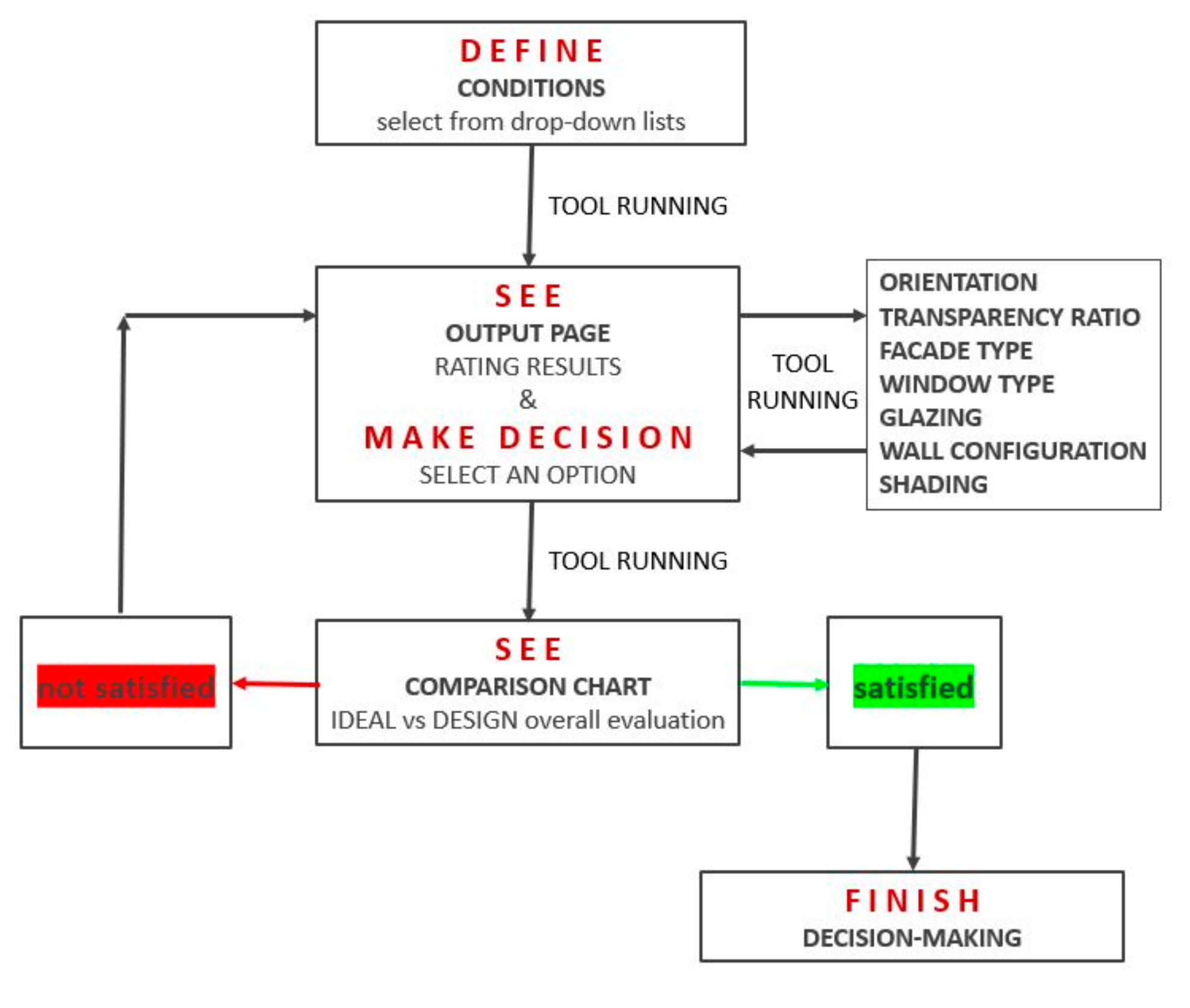
The tool user proceeds from the input page to the output and decision-making pages, and finally to the evaluation page. If required, the tool process pages can be accessed to see the logic behind the ratings. Step by step, the tool user defines the conditions by selecting from drop-down lists, then sees rating results for decision subjects, and selects an option for each, respectively. Afterward, the tool user checks the comparison chart for the overall performance evaluation. Finally, if the results are satisfying, the user finishes the decision-making; if not, the user goes back and rechecks the decisions. The flowchart for tool usage is shown in
Figure 6.
3.7. Testing of the Tool
The developed tool was tested for five different scenarios having various environmental and spatial conditions. Istanbul, Ankara, Antalya, Gaziantep, and Erzurum were chosen as the cities for the scenarios. These cities represent different climate types of Turkey: temperate-humid, temperate-arid, hot-humid, hot-arid, and cold climates. Details of the scenarios are given in
Table 2. Scenarios were defined in order to constitute a variety within the tool’s capacity. Furthermore, among the tool’s design decision options, random selections were made for each scenario.
4. Results
Based on the input data, the tool gave the ideal decisions for each scenario. Comparisons of the tool’s ideal decisions and the decisions of the facade design (the options selected by the user, here the author) are presented in
Table 3,
Table 4,
Table 5,
Table 6 and
Table 7. The aggregation of design decisions constitutes a total score for each performance aspect. Comparison charts that provide an overall performance evaluation for the facade designs together with their total scores are given in
Table 8. The total score of a facade for a performance aspect was calculated by accumulating the scores coming from design decisions having an impact on that performance aspect. The sum of (+) and (−) is (0). One advantage scored due to a decision plus one disadvantage scored due to another decision make the facade design neutral (having no superiority) for that performance aspect. (0) has no effect in the graphic (
Figure 7).
As seen in
Figure 7, a single decision may increase the score in one aspect while decreasing it in another aspect or vice versa. As an example, to select southeast instead of east decreases the structural performance while increasing the performance for all other aspects.
5. Validation
To evaluate the practicability of the tool and to come to a better conclusion, we conducted a series of interviews with the stakeholders of seven different projects from the same institution (educational) after allowing them to use the tool or see the tool’s outcomes. A classroom facade from each project was tested by the tool. The evaluation results are presented in
Table 9.
The classrooms are on the second floor of the schools except for the classroom in the Istanbul Dragos College. It is on the first floor. Three of them are in Istanbul in different locations, whereas the remaining ones are in different cities in Turkey. All the cases have specific environmental conditions in terms of climate, wind, and noise. On the other hand, the spatial conditions of the cases are similar. Classrooms have uniform room proportions, having light-colored interior surfaces. All the cases have a single-skin, infill-type facade with aerated concrete masonry units and a window. All of them have 50% transparency ratio and operable windows. The facades differ from each other with respect to orientation, window position (flush or recessed), glazing type, and shading. However, none of them demonstrates the same performance as the tool’s ideal.
The interviews were conducted with the institution’s main project team. Prior to the interviews, the tool was used by architects for some projects, while the tool’s outcomes (comparison of design decisions and performance evaluation charts) were provided to the remaining stakeholders for the other projects. Client-owners, architects, and engineers (structural and mechanical) were the professionals asked for their opinions through semi-structured, open-ended questions.
The interviews demonstrate that the tool is generally approved by the stakeholders. The general opinion of the stakeholders is itemized below.
The tool outcomes are easily comprehensible.
The tool is mainly for architects.
It is good to know the reasoning process behind the design decisions.
It is good to see the compromises in design in the early stages.
It is good to see the potential gains in performance by changing decisions.
The tool can contribute to the communication between architect and stakeholders in technical aspects.
It is new to see/evaluate the different facade performance aspects altogether.
The tool is preferred to be used.
The tool is found beneficial for providing a transparent decision-making process.
6. Discussion
The results of the tool do not give real performance values or mean that a facade design fails or passes. Considering the tool’s objective functions, it indicates that more proper design options may exist that can balance the relationships between the performance aspects in line with the conditions. The common ground of the objective functions embedded in the tool is to achieve maximum performance with minimum effort.
Even though some significant factors such as budget, feasibility, etc., were kept out of the scope, the tool gives users the opportunity to compare options for their price/performance ratios by providing their performance footprints. Moreover, decisions regarding aesthetics (which is not a technical function) are left to the users to be made according to the project context, architectural intentions, etc.
The tool tries to gather the variables and their consequences in one equation and aims to particularly support the inexperienced decision makers by indicating the performance tendency of the facade after each decision made. It is a kind of advice tool for use during the early stages of facade design. The tool does not aim to take the place of simulation or testing tools. On the contrary, it aims at decreasing the design alternatives in order to contribute to the simulation and testing processes.
On the other hand, a sensitivity analysis is necessary to check the degree of changes in the results (performance scores) by changing each decision individually and keeping the remaining ones constant at least in one scenario. Although the sensitivity analysis was kept out of the scope of this paper, we find it beneficial to briefly present the remarkable results of the analysis. The results demonstrate that all the aspects of facade performance are highly sensitive to the orientation parameter. The facade performance shows the least sensitivity to facade type, except for the structural and acoustic aspects. Furthermore, daylighting and acoustic performances of the facade are highly sensitive to the glazing parameter. The sensitivity analysis shows how important the orientation is on the overall design and performance.
As the testing results are examined, it can be seen that the tool’s ideal design decisions change with varying conditions. As soon as the most advantageous option is chosen for the first decision subject (orientation), that is, ratings, the most advantageous and disadvantageous options change for the consecutive decision subjects. The decision-making is defined as a dynamic and highly interactive process. Moreover, the results indicate that the tool’s ideal can have lower scores for some performance aspects. That is because the tool considers the decision-making in a holistic way, taking all the aspects into account for each design decision (facade parameter).
It can be seen in
Figure 8 from the first decision (facade parameter) that all decisions are linked to each other. The tool’s ideal orientation for the İzmir Bornova case is south, so the remaining decisions are proposed by the tool correspondingly. If this final design decision comparison does not work for the tool user, it is better to check the rating charts that give the advantageous and disadvantageous options for each facade parameter. As an example, as is seen in
Figure 8, the tool’s ideal shading is an overhang, which is in accordance with the south orientation and is not an ideal option for the east orientation. The tool’s ideal facade design that is composed of the most advantageous facade parameter options must be considered as a package of decisions; in other words, they must be evaluated holistically.
Similarly, decision makers can use the tool by selecting the options which are not under their control and allowing the tool to present them with the most proper (ideal) options for the remaining design decisions which are under their control. For example, in the Izmir Bornova case, if the decision makers must orientate the facade towards the east, and in order to have a highly transparent facade such as 75%, then the tool recommends an infill masonry facade type which used to be an infill frame facade type (offering a lighter structure for the wall) to compensate for the potential heat loss, or loss in sound insulation with the wall part. Furthermore, the tool proposes heavier infill gases with low-e coating for the glazing and a vertical louver for the shading, which are totally different from the ones proposed for the south-oriented facade with 25% transparency ratio. Therefore, with the tool’s recommendations, it is possible to get closer to the performance scores of the ideal design proposed by the tool, no matter what the initial decisions are (orientation and transparency ratio in this case).
The tool assumptions can evolve as the tool is used by the stakeholders. The relationships between conditions and functions and the coefficients of the relationships can be refined. Moreover, orientation can be defined as a condition rather than a decision, since the final results or the subsequent decisions totally change with this parameter.
It is believed that the tool will guide the decision makers of facade design, providing a special emphasis on the interactions of performance aspects among each other and with facade parameters. This will lead to holistic design.
7. Conclusions
Facade design, which has always been a complex task, is getting more complicated with today’s increasing requirements. The constraints are getting harsher, such as the shortage of energy and material sources, while the comfort expectations are rising. Facades may need to respond to today’s trends such as a sustainable or ecological design. Moreover, design options are increasing in number, becoming almost limitless, and consequently making decision-making harder than ever. The present age of speed is forcing the design of facades within a very limited time. In addition to these points, decision makers of facade design may be technically incapable, and there can be conflicting aspects in design.
A holistic decision support tool for use during the early stages of facade design is presented in this paper. The tool draws a framework to maintain the holism through the entire decision-making process in facade design. It provides the notion of interrelations among performance aspects, design decisions, and conditions.
As the outcome of this research, we believe the tool has a significant contribution to make to the early stages of facade design by saving time, labor, and cost accordingly. Using the proposed design decision support tool, stakeholders of the facade design process may give faster and more proper decisions and maintain more efficient collaborations. Because these stakeholders operate within different disciplines’ areas of interest, it is essential to design this building sub-system in a systematic way. In one sense, design is a process of limiting possible alternatives, and in this context, the tool may function as supportive guidance.
Use of the tool may prevent negative iterations in design and reduce the time reserved for the simulations of numerous alternatives. Each stakeholder may benefit from a different aspect of the tool while perceiving the whole facade design. With these attributes, the tool may make the process easier.
However, project conditions may vary, as can the importance factors (relationship coefficients) of the performance aspects. In that case, design decisions can be given accordingly, which makes the tool flexible with respect to changing priorities and conditions. All relevant adjustments can be made as long as they are based on the developed tool.
It is believed that the tool provides a holistic perspective to the scientific knowledge regarding facade performance and design. Its use was validated by the main decision makers of the building design process. In addition to this, it can upgrade itself in terms of assumptions, weights, etc., while being used by the design stakeholders.
In future studies, design options within the scope of the tool can be expanded and rated by following a similar logic. Furthermore, the tool can be customized for specific climatic conditions or building or facade types. It may evolve in the future, as new knowledge is incorporated into the tool.


