High-Strength Concrete Circular Columns with TRC-TSR Dual Internal Confinement

Abstract
1. Introduction
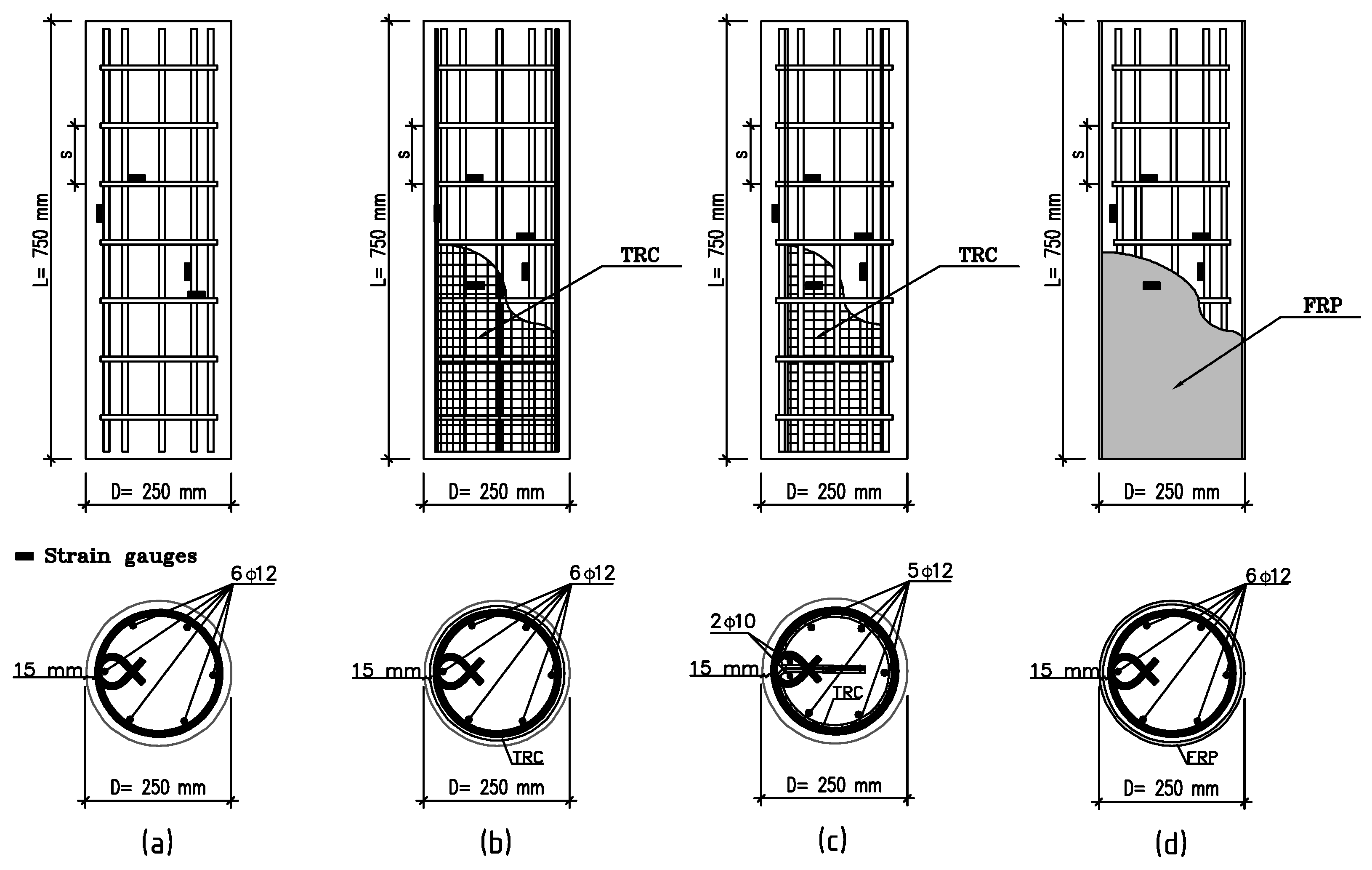
2. Experimental Program
2.1. Material Properties
2.1.1. Concrete
2.1.2. Textile Fiber-Reinforced Concrete—TRC
2.1.3. Steel Reinforcement
2.1.4. Fiber-Reinforced Polymer—FRP
2.2. Instrumentation and Test Setup
3. Discussion
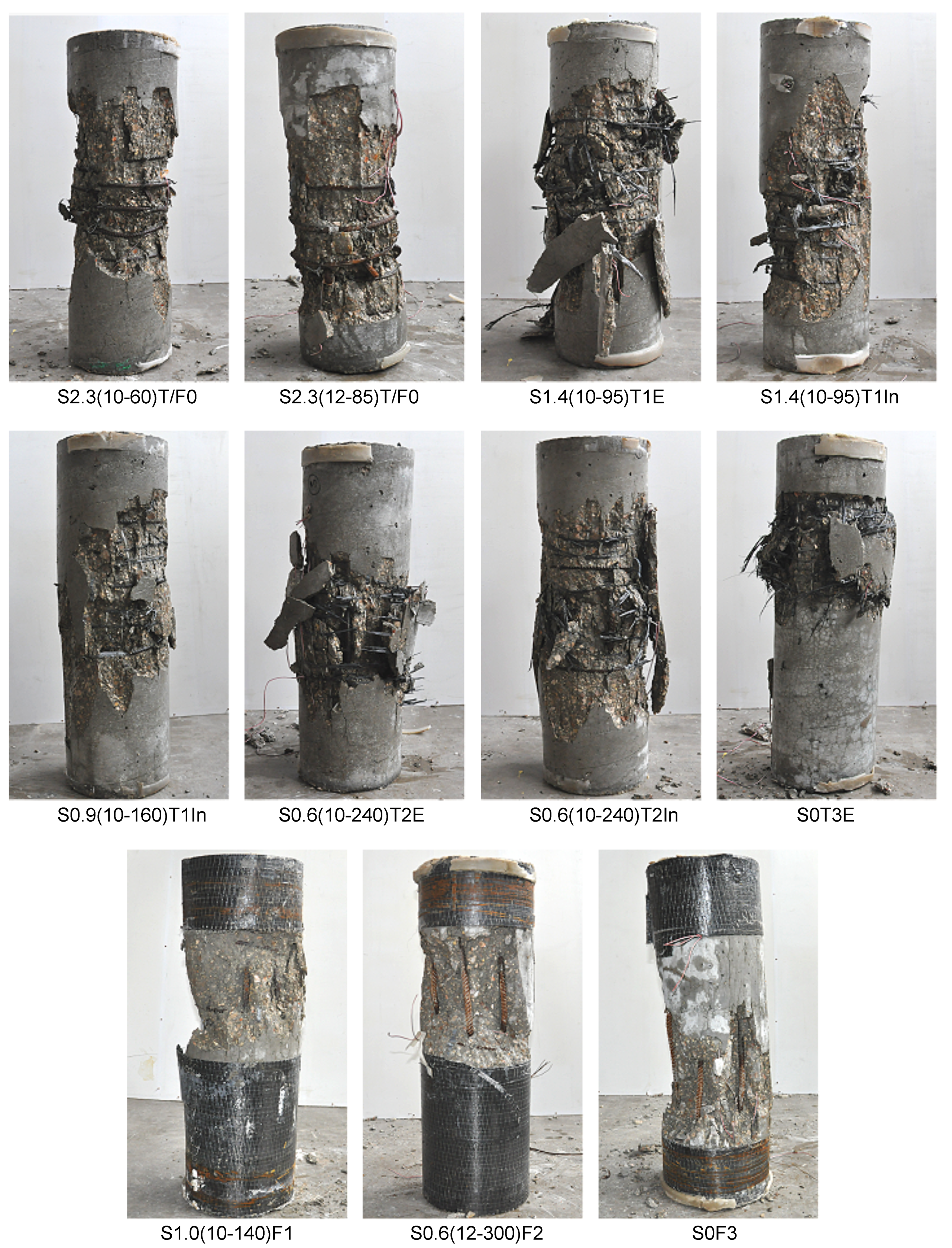
3.1. General
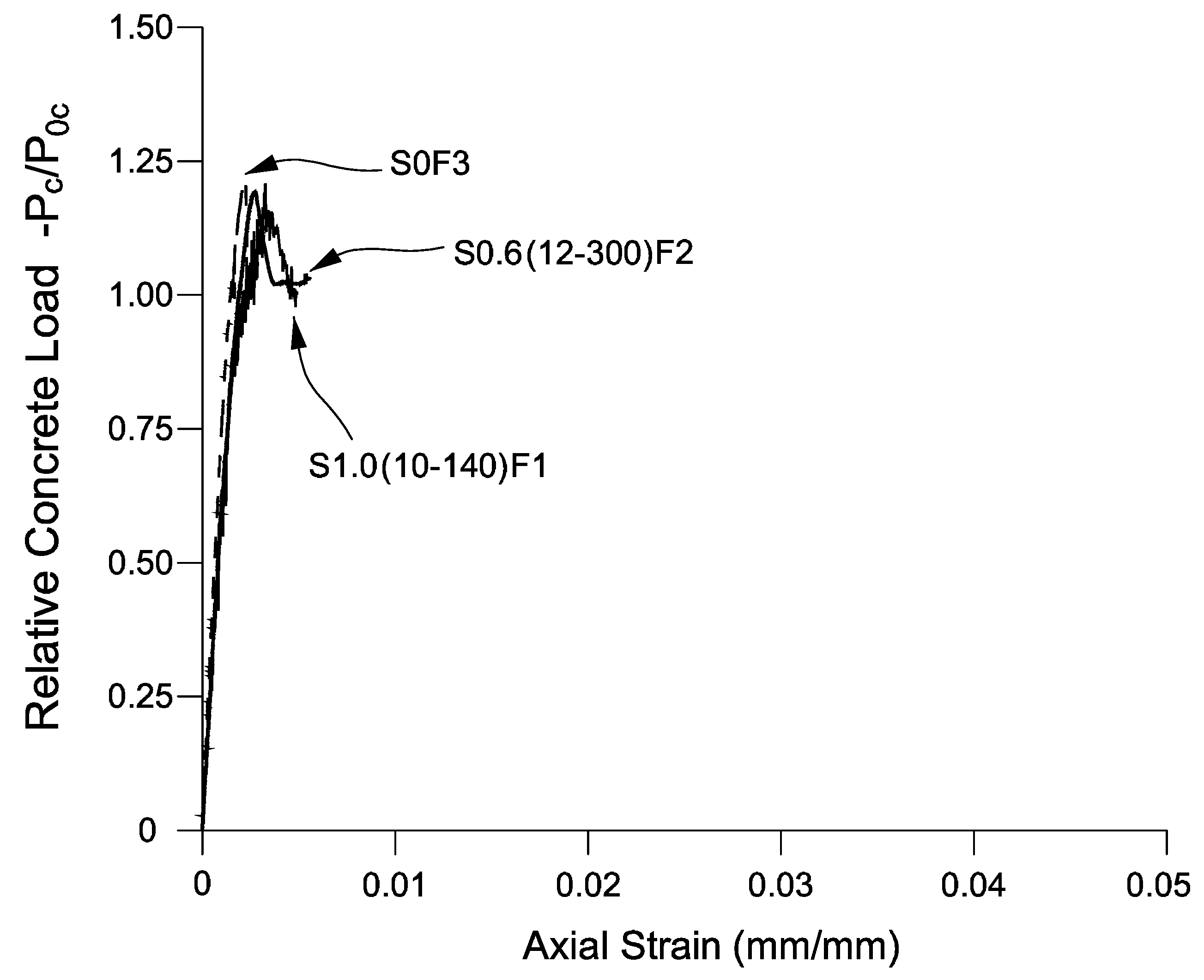
3.2. Analysis of Test Results
4. Conclusions
Author Contributions
Funding
Acknowledgments
Conflicts of Interest
Abbreviations
| TRC | Textile reinforced concrete |
| TSR | Transverse steel reinforcement |
| FRP | Fiber-reinforced polymer |
| NSC | Normal-strength concrete |
| HSC | High-strength concrete |
| RC | Reinforced-concrete |
| SFRS | Seismic-force-resisting system |
References
- Eid, R.; Kovler, K.; David, I.; Khoury, W.; Miller, S. Behavior and design of high-strength circular reinforced concrete columns subjected to axial compression. Eng. Struct. 2018, 173, 472–480. [Google Scholar] [CrossRef]
- Légeron, F.; Paultre, P. Behavior of High-Strength Concrete Columns under Cyclic Flexure and Constant Axial Load. ACI Struct. J. 2000, 97, 591–601. [Google Scholar]
- Paultre, P.; Eid, R.; Robles, H.I.; Bouaanani, N. Seismic Performance of Circular High-Strength Concrete Columns. ACI Struct. J. 2009, 106, 395–404. [Google Scholar]
- Aslani, F.; Nejadi, S. Cyclic Constitutive Model for High-Strength Concrete Confined by Ultra-High-Strength and Normal-Strength Transverse Reinforcements. Aust. J. Struct. Eng. 2012, 12, 159–172. [Google Scholar]
- American Concrete Institute ACI 318. Building Code Requirements for Structural Concrete; ACI: Farmington Hills, MI, USA, 2014. [Google Scholar]
- New Zealand Standard 3101. Concrete Structures Standard, Part 1—The Design of Concrete Structures; Standards New Zealand: Wellington, New Zealand, 2006. [Google Scholar]
- Canadian Standard Association (CSA) A23.3. Design of Concrete Structures; CSA: Mississauga, ON, Canada, 2014. [Google Scholar]
- European Standard EN 1998-1. Eurocode 8: Design of Structures for Earthquake Resistance. Part 1: General Rules, Seismic Actions and Rules for Buildings; European Committee For Standardization: Brussels, Belgium, 2004. [Google Scholar]
- Ozbakkaloglu, T.; Oehlers, D.J. Concrete-Filled Square and Rectangular FRP Tubes under Axial Compression. ASCE J. Compos. Constr. 2008, 12, 469–477. [Google Scholar] [CrossRef]
- Ozbakkaloglu, T. Axial Compressive Behavior of Square and Rectangular High-Strength Concrete-Filled FRP Tubes. ASCE J. Compos. Constr. 2013, 17, 151–161. [Google Scholar] [CrossRef]
- Han, L.H.; Zheng, Y.Q.; Teng, J.G. Fire resistance of RC and FRP-confined RC columns. Mag. Concr. Res. 2006, 58, 533–546. [Google Scholar] [CrossRef]
- Echevarria, A.; Zaghi, A.E.; Christenson, R.; Plank, R. Residual Axial Capacity Comparison of CFFT and RC Bridge Columns after Fire. Polymers 2015, 7, 876–895. [Google Scholar] [CrossRef]
- Firmo, J.P.; Correia, J.R.; Bisby, L.A. Fire behaviour of FRP-strengthened reinforced concrete structural elements: A state-of-the-art review. Compos. Part 2015, 80, 198–216. [Google Scholar] [CrossRef]
- Triantafillou, T.C.; Papanicolaou, C.G.; Zissimopoulos, P.; Laourdekis, T. Concrete confinement with textile-reinforced mortar jackets. ACI Struct. J. 2006, 103, 28–37. [Google Scholar]
- Bournas, D.A.; Lontou, P.V.; Papanicolaou, C.G.; Triantafillou, T.C. Textile-reinforced mortar versus fiber-reinforced polymer confinement in reinforced concrete columns. ACI Struct. J. 2007, 104, 740–748. [Google Scholar]
- Ortlepp, R.; Ortlepp, S. Textile reinforced concrete for strengthening of RC columns: A contribution to resource conservation through the preservation of structures. Constr. Build. Mater. 2017, 132, 150–160. [Google Scholar] [CrossRef]
- Liu, M.; Yin, S.-P.; Cong, X. Seismic behavior of textile-reinforced concrete-strengthened RC columns under different axial compression ratios. J. Eng. Fibers Fabr. 2019, 14, 1–11. [Google Scholar]
- Al-Gemeel, A.N.; Zhugea, Y. Using textile reinforced engineered cementitious composite for concrete columns confinement. Compos. Struct. 2019, 210, 695–706. [Google Scholar] [CrossRef]
- Cerniauskas, G.; Tetta, Z.; Bournas, D.; Bisby, L.A. Textile reinforced mortar versus FRP for confined concrete: Behaviour at elevated temperatures. In Proceedings of the 8th International Conference on Fibre-Reinforced Polymer (FRP) Composites in Civil Engineering (CICE 2016), Hong Kong, China, 14–16 December 2016. [Google Scholar]
- Eid, R.; Cohen, A.; Guma, R.; Ifrach, E.; Levi, N.; Zvi, A. Multi-layer TRC-TSR internal confinement for high-strength circular reinforced-concrete columns. In Proceedings of the 9th International Conference on Fibre-Reinforced Polymer (FRP) Composites in Civil Engineering (CICE 2018), Paris, France, 17–19 July 2018. [Google Scholar]
- Eid, R.; Roy, N.; Paultre, P. Normal- and high-strength concrete circular elements wrapped with FRP composites. ASCE J. Compos. Constr. 2009, 13, 113–124. [Google Scholar] [CrossRef]
- Cusson, D.; Paultre, P. High-Strength Concrete Columns Confined by Rectangular Ties. ASCE J. Struct. Eng. 1994, 120, 783–804. [Google Scholar] [CrossRef]


| Specimen | TSR | TRC | FRP | ||||||||||
|---|---|---|---|---|---|---|---|---|---|---|---|---|---|
| D | L | s | |||||||||||
| (MPa) | (mm) | (mm) | (MPa) | (mm) | (mm) | (%) | (GPa) | (mm) | (GPa) | (mm) | |||
| S2.3(10-60)T/F0 | 548 | 10 | 60 | 2.27 | – | – | – | – | |||||
| S2.3(12-85)T/F0 | 580 | 12 | 85 | 2.29 | – | – | – | – | |||||
| S1.4(10-95)T1E | 548 | 10 | 95 | 1.43 | 1 (ext.) | 0.0785 | – | – | |||||
| S1.4(10-95)T1In | 548 | 10 | 95 | 1.43 | 1 (int.) | 0.0785 | – | – | |||||
| S0.9(10-160)T1In | 548 | 10 | 160 | 0.85 | 1 (int.) | 0.0785 | – | – | |||||
| S0.6(10-240)T2E | 74.2 | 250 | 750 | 548 | 10 | 240 | 0.57 | 240 | 2 (ext.) | 0.1570 | – | – | |
| S0.6(10-240)T2In | 548 | 10 | 240 | 0.57 | 2 (int.) | 0.1570 | – | – | |||||
| S0T3E | – | – | – | – | 3 (ext.) | 0.2355 | – | – | |||||
| S1.0(10-140)F1 | 548 | 10 | 140 | 0.97 | – | – | 1 | 0.113 | |||||
| S0.6(12-300)F2 | 580 | 12 | 300 | 0.65 | – | – | 240 | 2 | 0.226 | ||||
| S0F3 | – | – | – | – | – | – | 3 | 0.339 | |||||
| Variable | (kg/m) |
|---|---|
| Cement | 460 |
| Water | 150 |
| Coarse aggregate— | 550 |
| Intermediate aggregate— mm | 900 |
| Fine aggregate—quartz sand | 220 |
| High-Range Water Reducer | 9 |
| Polypropylene Fibers | 1 |
| Fly Ash | 100 |
| Slump (mm) | 175 |
| Water to cementitious materials (w/cm) | 0.27 |
| Axial Loads | Axial Strains | |||||||||||
|---|---|---|---|---|---|---|---|---|---|---|---|---|
| Specimen | (kN) | (kN) | (kN) | () | () | |||||||
| S2.3(10-60)T/F0 | 3996 | 1.16 | 3677 | 1.20 | 3142 | 1.47 | 0.0024 | 0.87 | 0.0040 | 1.47 | 0.0191 | 7.04 |
| S2.3(12-85)T/F0 | 3407 | 0.99 | 3023 | 0.99 | 2867 | 1.34 | 0.0030 | 1.09 | 0.0040 | 1.47 | 0.0208 | 7.66 |
| S1.4(10-95)T1E | 3813 | 1.11 | 3515 | 1.15 | 3155 | 1.47 | 0.0022 | 0.81 | 0.0033 | 1.21 | 0.0104 | 3.82 |
| S1.4(10-95)T1In | 3362 | 0.97 | 3029 | 0.99 | 2728 | 1.28 | 0.0023 | 0.85 | 0.0032 | 1.19 | 0.0074 | 2.71 |
| S0.9(10-160)T1In | 3075 | 0.89 | 2778 | 0.91 | 2461 | 1.15 | 0.0021 | 0.76 | 0.0035 | 1.29 | 0.0070 | 2.60 |
| S0.6(10-240)T2E | 3444 | 1.00 | 3167 | 1.04 | 2835 | 1.32 | 0.0020 | 0.75 | 0.0029 | 1.08 | 0.0059 | 2.19 |
| S0.6(10-240)T2In | 3300 | 0.95 | 2925 | 0.96 | 2720 | 1.27 | 0.0026 | 0.96 | 0.0032 | 1.17 | 0.0055 | 2.03 |
| S0T3E | 3338 | 0.97 | 3058 | 1.00 | 2917 | 1.36 | 0.0021 | 0.76 | 0.0030 | 1.11 | 0.0052 | 1.93 |
| S1.0(10-140)F1 | 3979 | 1.15 | 3688 | 1.21 | – | – | 0.0033 | 1.21 | – | – | 0.0049 | 1.82 |
| S0.6(12-300)F2 | 3894 | 1.13 | 3638 | 1.19 | 3129 | 1.49 | 0.0027 | 1.01 | 0.0042 | 1.53 | 0.0056 | 2.06 |
| S0F3 | 3996 | 1.16 | 3713 | 1.22 | 3547 | 1.66 | 0.0022 | 0.82 | 0.0033 | 1.22 | 0.0033 | 1.22 |
© 2019 by the authors. Licensee MDPI, Basel, Switzerland. This article is an open access article distributed under the terms and conditions of the Creative Commons Attribution (CC BY) license (http://creativecommons.org/licenses/by/4.0/).
Share and Cite
Eid, R.; Cohen, A.; Guma, R.; Ifrach, E.; Levi, N.; Zvi, A. High-Strength Concrete Circular Columns with TRC-TSR Dual Internal Confinement. Buildings 2019, 9, 218. https://doi.org/10.3390/buildings9100218
Eid R, Cohen A, Guma R, Ifrach E, Levi N, Zvi A. High-Strength Concrete Circular Columns with TRC-TSR Dual Internal Confinement. Buildings. 2019; 9(10):218. https://doi.org/10.3390/buildings9100218
Chicago/Turabian StyleEid, Rami, Avi Cohen, Reuven Guma, Eliav Ifrach, Netanel Levi, and Avidor Zvi. 2019. "High-Strength Concrete Circular Columns with TRC-TSR Dual Internal Confinement" Buildings 9, no. 10: 218. https://doi.org/10.3390/buildings9100218
APA StyleEid, R., Cohen, A., Guma, R., Ifrach, E., Levi, N., & Zvi, A. (2019). High-Strength Concrete Circular Columns with TRC-TSR Dual Internal Confinement. Buildings, 9(10), 218. https://doi.org/10.3390/buildings9100218