1. Introduction
Industrialisation of the construction industry through prefabrication has been noted as an effective method to achieve higher performance levels through moving more and more processes into a controlled manufacturing environment [
1]. This results in improvements in quality and efficiency as lean manufacturing principles and automation are introduced [
2]. Thus great potential lies in including as many construction processes in which we can practically complete in such ways.
Prefabrication in the modern construction industry generally comes closed/complete such as in some panelised or modular systems or open/incomplete such as pods and stick and frame assembly, however there are also open panelised systems or un-cladded and hence incomplete modular systems, to fully prefabricate a building it must be complete be it in pieces which require assembling but complete nonetheless [
3]. The most complete systems for walls would be those which include internal finish to external façade and likewise for floors those which includes from ceiling to flooring and everything in-between or at least with built in provision for electrical, water, gas and heating, ventilation and air condition (HVAC) systems.
There are many intrinsic challenges to fully prefabricate a building such as flexibility of design and method of connections, currently parts of industry have adapted to prefabrication by picking and choosing which processes are most valuable to them to incorporate in prefabrication [
4]. These have generally been either major labour and skill intensive processes such as sawing and cutting which can be replaced with computer numerical control (CNC) machines or simple tasks which are easy to automate such as nailing or gluing.
This research study expands on the processes which are currently greatly prefabricated to also include the façade, specifically the weatherproofing between façade panels, wall panels and modules. Currently the convention means of onsite weatherproofing of gaps entails setting up scaffolding to reach work height, manually pushing in a flexible foam backing rod and then manually applying a caulking/sealant generally silicone then manually tooling to achieve the correct profile are adopted for prefabricated panelised and modular constructions in filling the gaps between each wall or module [
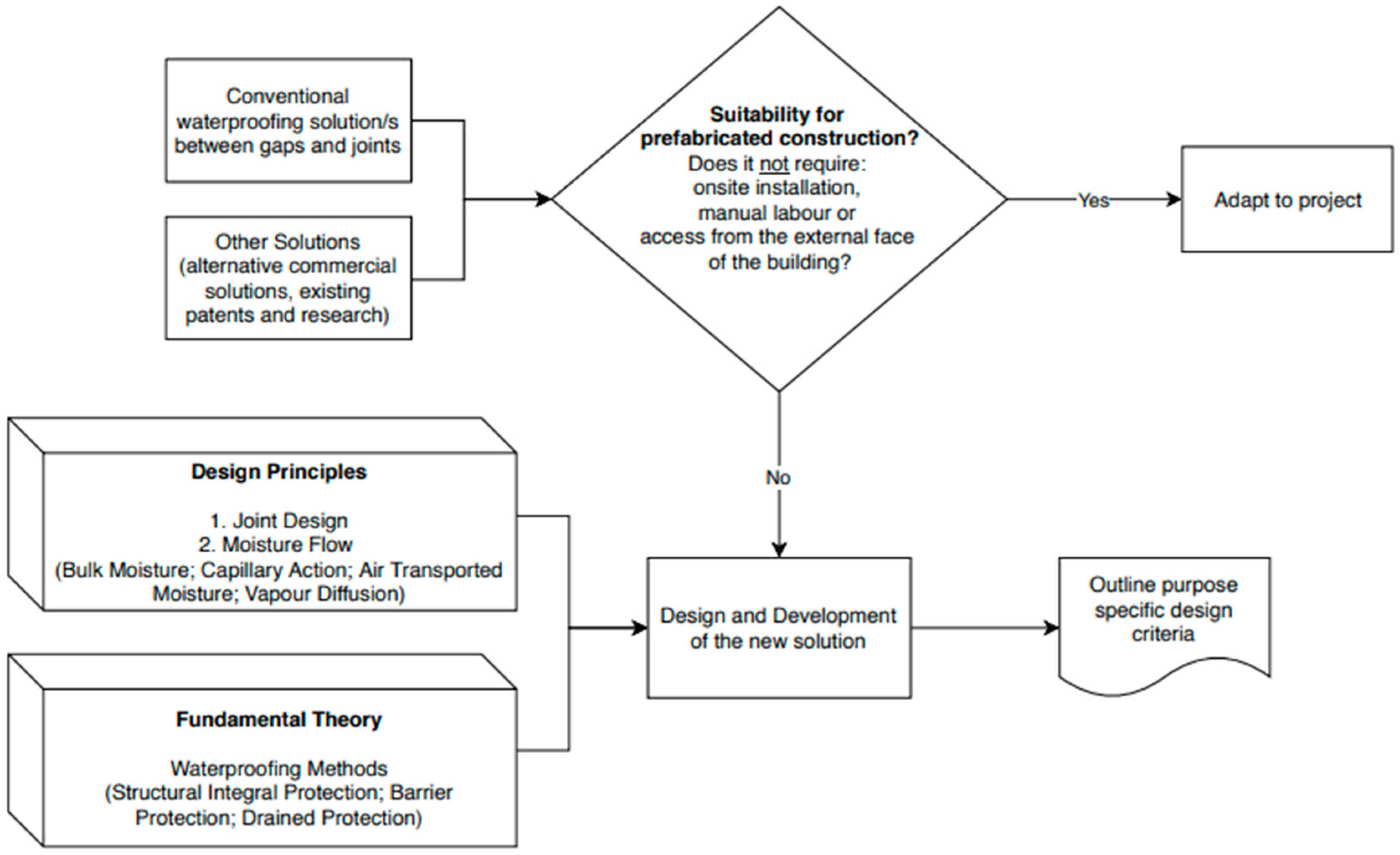
5]. This labour intensive primitive means of weatherproofing does not align directly with the values of efficiency in prefabrication. Quicker means of weatherproofing specifically designed for prefabricated panelised and modular type of construction and assembly is in order. Design and development of new solutions for purpose sake is only done when conventional or other solutions cannot suffice. To fuel design and development an understanding of the design principles and fundamental theory is required along with a purpose specific set of design criteria which are encompassing of the entire design, manufacturing and assembly processes [
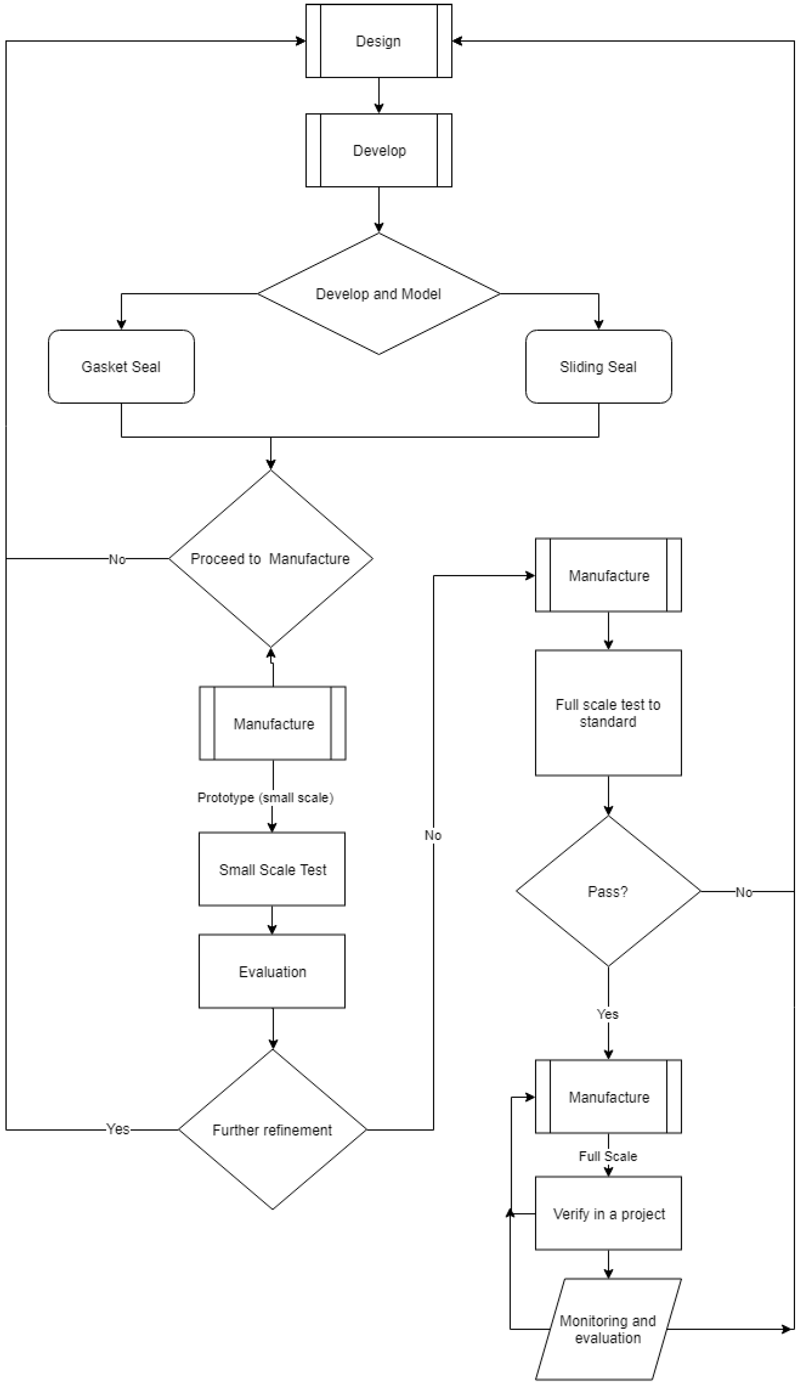
6]. To evaluate this need for design and development the flow chart in
Figure 1 below is used and demonstrated in the following sections.
2. Conventional Solution
Current practice which is considerably widespread for the filing and sealing of joints is grouting and another is the backer rod and caulking/sealant solution. Grouting involves using a cementitious material to fully seal and join the gap between two other cementitious materials [
7]. This wet trade is much easier done on horizontal joins such as those in bridge decks [
8] where the gaps are manually filled onsite with a viscous cementitious grout. In this process pre-moistening the surface is recommended to enhance the performance of the bond [
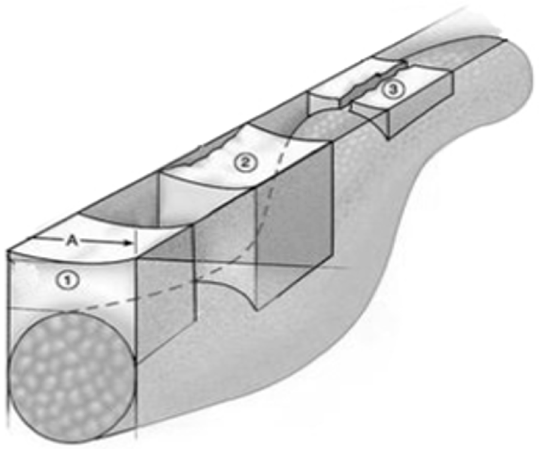
9]. The limiting factors of grouting is that it is constrained to joining between cementitious surfaces, better suited for horizontal and not vertical gaps and joins and requires onsite manual labor all of which do not lend to an efficient and versatile prefabrication sealing solution for vertical joins in prefabricated walls and or modules. As for the backer rod and caulking/sealant solution the procedure begins with a worker who is at the working height for the entire height of a wall which makes it considerably unpractical and dangerous for taller buildings. The worker must clean both surfaces properly then manually push in a flexible foam backing rod to a specified distance along the entire length of the wall and then manually apply a caulking/sealant (generally silicone) along this length then manually tool it to achieve the correct hourglass profile as shown in the foreground on
Figure 2.
Since there are so many labour intensive steps workers often take shortcuts to which have consequences later in the buildings life. For example pushing the backing rod too far in may result in adhesion failure as the layer of caulking/sealing must not be too thick as not to be able to accommodate for the tolerances required when the building/panels move be it due to thermal expansion or for dynamic reasons [
10]. The adhesion fails and separation occurs as the caulking/sealant is not in the narrow hourglass figure and hence the increase pulling force acting against the adhesion.
If the rod is too close to the surface there may not be enough cohesive force in the caulking/sealant for such a narrow section. Additionally if the walls are not cleaned properly and free from dust prior to installation of the backer rod and caulking/sealant then separation will occur. Lastly if the width of the gap varies that is the tolerances are not all the same then an appropriately sized backing rod and appropriately profiled section must be done otherwise splitting will occur. Using sealant as the primary means of weatherproofing without further protection such as a drained joint is fundamentally not a rigorous solution especially considering that the joint can only be inspected from the outside. The time where the use of sealant that can be best relied upon in this manner is when used between glass to glass joint’s where both sides can be easily inspected and the design requires openness [
11].
Poor workmanship along with sealant distress are amongst the leading reasons for why a building will leak [
11]. Therefore there is a need to develop new seals which do not rely as heavily on workmanship and are able to be completed offsite are required for prefabricated forms of construction.
3. Other Solutions
There may be non-conventional means which could be adapted (or at least learnt from) to solve the limiting requirements of sealing fully finished prefabricated walls and modules.
The first of which will be discussed is Shopfront framing systems. These systems are used in podium level/ground level façade, they may be external and exposed to weather elements such as in a standalone retail outlet or internal such as in shopping centre. There are many varieties of such systems which vary the frame depth, glazing position (such as flush to outside or centre of frame) which integrates with fixed, sliding, bi-fold, automatic doors and louvres. They often have simpler design then curtain wall systems as their as less design requirements for a single level as compared to multi-level construction.
The next solution discussed is the curtain wall system. Curtain walls differ to shopfront framing systems in that curtain walls can span many floor levels and take into many more design considerations such as thermal expansion, building swap, water drainage, thermal performance and lighting. “Curtain” in the sense of curtain wall refers to the fact that it is hanging off the building, it does not carry any vertical load except its own and transfers the wind load to the structure. Its fundamental nature of being affixed externally to the principle building structure holds a strong advantage in that it does not rely critically on the structural tolerances for it to be installed successfully and work to its designed performance criteria. For this reason curtain walling is a popular method of façade construction and is often used in commercial and residential high-rise towers.
Curtain walls are made and assembled primarily in two ways, stick built curtain walls and unitized curtain walls.
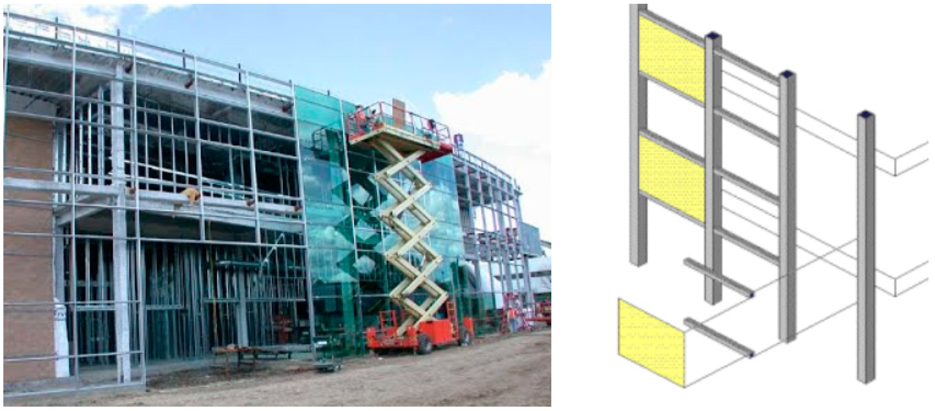
With stick built systems as shown in
Figure 3, the vertical (mullion) and horizontal (transom) members are installed on site often with elements spanning multiple floors and widths, the glazing is then installed on site afterwards. It requires installation by highly skilled workers however the onsite work allows for greater tolerances, this type of curtain wall is generally used on small scale or low rise buildings.
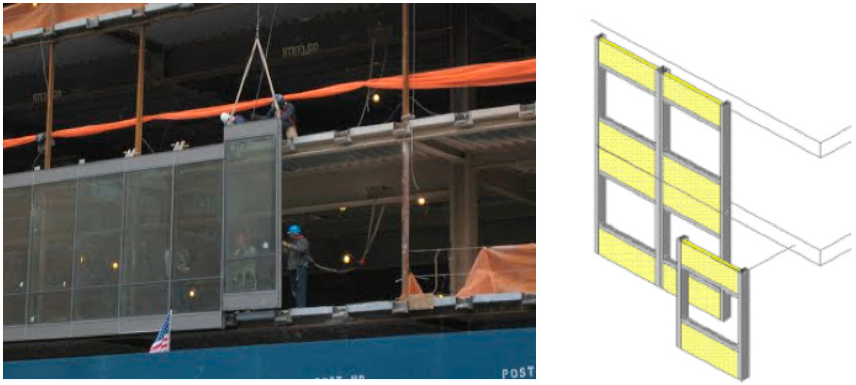
Unitized curtain walls come in panelised form with the glazing and framing complete, thus they are sometimes referred to as modular system or panel system, an example is shown in
Figure 4. The panels are prefabricated offsite and lifted into place and secured and weather proofed onsite and thus reduce the installation time onsite along with the number of labourer’s onsite, this system is most used in mid to high rise structures due to economy of scale. The curtain wall system can be ‘unitized’ in that large sections can be made in a manufacturing facility and stacked onto a truck and carefully brought to site and craned into positon. This means that there is less work to be done on site which is beneficial to rapid multi story constructions however between each unitized section a water and weather proof seal is needed to be made. This is usually done with a gasket, foam backing road and sealant or with its own pressure plate and cover [
5]. The most convenient of these is that gasket as it does not require installation to be done from the external face which is key advantage for multi-level construction.
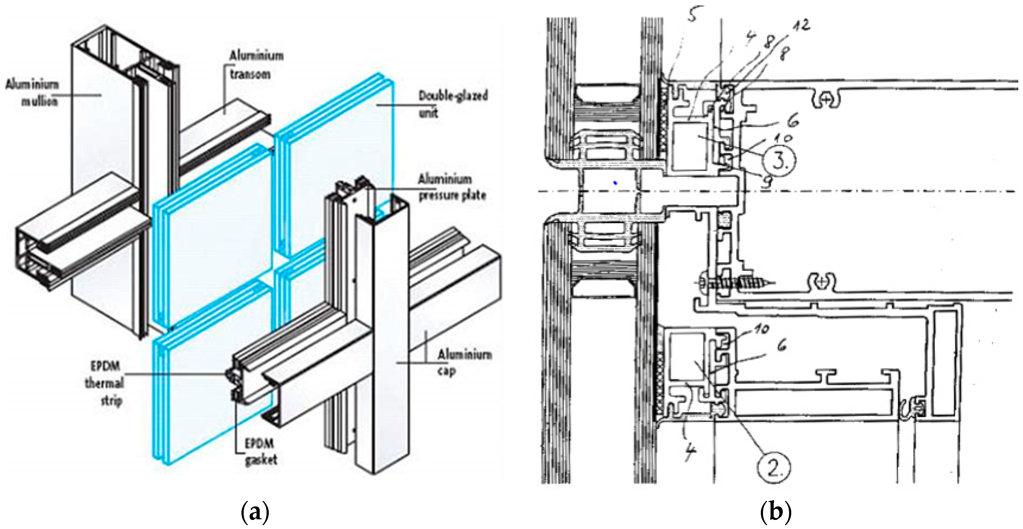
The gaskets used in these kind of facades are often referred to as ‘pressure plates’ or ‘pressure bars’ and are fastened to the mullion in order to hold the glass and elsewhere to create waterproof joints. There are some additional positive carry on effects such as acoustic isolation and thermal breaks. The region in which the horizontal and vertical sections meet needs special consideration in terms of design especially given that with age and exposure to ultraviolet radiation shrinkage will occur [
13].
The method of affixing and geometry of section may vary however
Figure 5a displays the main components to most systems. The mullion and transoms are the vertical and horizontal framing elements respectively, they house the glazing, which is sandwiched with a pressure plate contains a rubber strip and gasket and compressed by screwing from the outside of the building through the centre of the pressure plate and into the mullion and transom, then finally a cover or cap is clipped on the outside of the pressure plates to hide the screws and give the system a finished clean look. A detailed schematic of a variant of this setup is shown in
Figure 5b.
Other than seeing what is currently practiced in industry and identifying a need which would then be planned out and a project conducted, one which has a major component of invention and product development a thorough review of patents office may be been carried out first to ensure this is indeed new work, that there isn’t anything else out there which can be used for this application and that the developed system doesn’t infringe on prior work. Starting with the US patent office and branching off from there searching for waterproof/weatherproof seals specifically designed for prefabrication construction has yielded no results and thus no potential conflicts. In this stage, the industry partner also verified this and the project advancement in this area was established. In this early stage understanding of concepts and deeper thought on the issue was provided by this thorough patent review of areas next closest, the more notable finds are outlined in
Table 1: Findings of Patent Review. These provided a means to generate an idea on how others have tackled relatable problems in the past however it was found that since the requirements are different so to the design of the seal and so the only notable finding was the assurance that the design developed did not overlap with any existing patents. This is important as one of the expected outcomes of this project is the commercialization of the seal solution developed for the waterproofing between panels in prefabricated construction.
A strong effort has been made to pair the prominent developments filed to patents offices with literature published after the time of filing to get an academic research perspective on the area, particularly on what is of interest to academia at large. In this way it was possible to verify that this was indeed a practicable and well justified project to undertake for industry—university collaboration along with how much emphasis shall be placed on either patents or literature.
Table A1 shows the prominent literature in this area, it was easily concluded that literature did not match the patent submission and that the content and focus of them are fundamentally different. In short, with the patents focus was in the design whereas with the literature focus was on a very narrow highly specific field mainly to do with material behaviour. It was found that there is a gap in literature to address the design of seals, the development of them let alone specific solutions for prefabricated purposes.
Table A1 below displays the most closest pieces of literature on this topic however it was found that the knowledge gap was clearly evident and that for the design and development of seals for timber based prefabricated panelised construction attention had to be focused from the basic principles behind the theory of weatherproofing and work on from there.
4. Fundamental Theory
In designing new waterproof seals looking at previous and conventional solutions only enables incremental changes and improvements. Since the very nature of prefabrication construction is fundamentally different than that of conventional means it begs us to look into the fundamental theory. In understanding the fundamental theory vast comprehensive lists of possible designs such as that in can be simplified to a much more tangible amount of working principles.
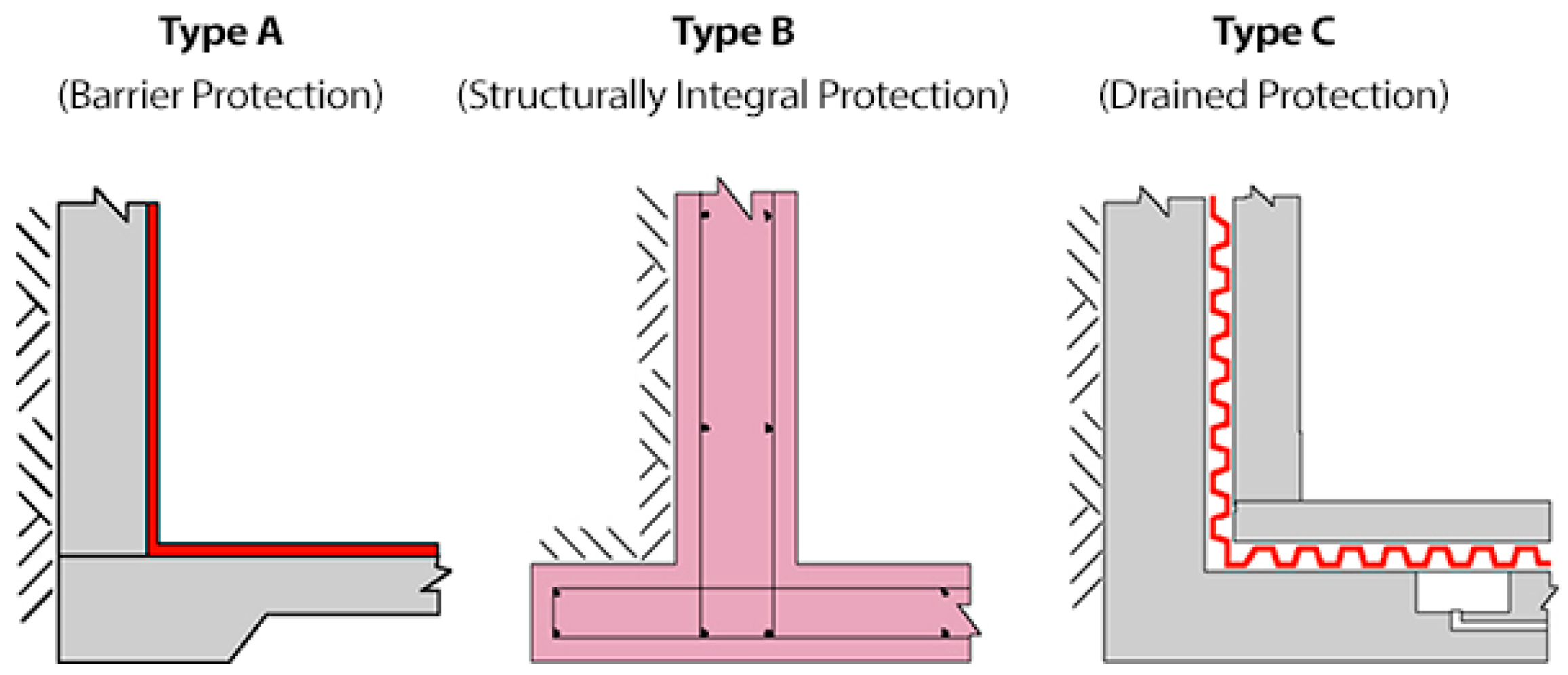
Waterproofing can be accomplished in many forms but can be categorized as shown in
Figure 6 they work on at least one of three fundamental levels:
The first fundamental method of waterproofing is that of Structural integral protection. The basis of structural integral protection is such that if the structure has no gaps of voids water cannot seep through. In façades or roofing the simplest form of structural integral protection would be overlapping of panels, this aims to create a continuous structure which prevents water ingress.
The next fundamental method of waterproofing is barrier protection. Barrier protection is the application of an impermeable material to fill a void/gap or cover an exposed or at risk area. In building construction a typical example of this would be membranes commonly known as building wraps. Another example of barrier protection is the conventional foam backing road and caulking/sealant method for filling gaps between panels such as concrete precast panels.
The final fundamental method of waterproofing is via drained protection. Drained protection encompasses a cavity for any ingressed water to channel its way down and out without it making its way inside a building, simply put water takes the path of least resistance and drained protection is giving it this path. This form of waterproofing can be found in many double skin/walled structures as it ensures that in worse case scenarios that water will not build up between skins/walls.
5. Design Principles
5.1. Moisture Flow
Reducing the flow of moisture is a key component in sealing joints and thus understanding the theory behind the types is important to design. There are four primary methods for moisture to flow through a building, they are: Bulk moisture, capillary action, air transported moisture and vapour diffusion.
Bulk moisture transfer is the first major form of moisture flow. Bulk moisture refers to the flow of liquid, this has the greatest immediate capacity to cause damage and failure of performance. Generally three factors must all be in play in order for bulk moisture transport to occur, they are: (1) Source of water, (2) a void/penetration in the buildings envelop and (3) an acting force such as gravity or air pressure in which to drive the movement of moisture. In general practice the key is to seal the building envelop and to direct the water away from the building [
30]. In designing of a sealing solution it would require addressing at least one of the formally mentioned requirements for bulk moisture to occur.
The next form of moisture flow is that of capillary action. Water has the ability to travel against gravity in in porous materials or in small gaps between non porous materials through surface tension effects, this behaviour is called capillary action. Methods in which to counter the effects of capillary action are: incorporating a plastic or other impermeable material to form a capillary break or to add an air space or void that is large enough for capillary action not to occur [
30]. In designing and developing a sealing solution one should consider capillary action and note that in testing it may take some time to occur as the process can be slow.
Another form of transfer of moisture is that via the means of air movement. The importance of a building envelop to be airtight is important not just for energy efficiency but also for waterproofing as small amounts of water often known as humidity, the higher the humidity the more moisture there is in the air, thus the infiltration of air leads to the infiltration of water. This occurs through a process called condensation which is the name of the process that turns humid air into droplets of water upon contact with a cold surface. Therefore the rate of condensation is dependent on how humid the air is, how cold the contacting surface is with respect to the humid air, the area of exposure and the time of exposure [
30]. Seals are ideally made of an insulating material and can work to prevent air transported moisture by keeping moist air on the external of the building envelop.
The final form of moisture transfer is that of vapour diffusion. Vapour pressure differential and the permeability of a material leads to small amounts of moisture to pass through a building envelop even if there are no holes or leaks. To slow this process and thus to help prevent this transfer of moisture to the building elements, vapour diffusion retarders are installed within the walls. In colder climate where heating of the building occurs, pressure differential drives vapour from the inside to the outside and thus vapour retarders are often installed on the interior face walls. The opposite is true for warmer climates when cooling of the building occurs, the pressure differential drives vapour from the outside to the inside and thus vapour retarders are often installed on the exterior face walls [
30]. In designing and developing a seal it is important to note the geographical location in which the seal will be used in along with the permeability of the material in question to provide the best sealing solution.
5.2. Joint Design
Design principles for waterproof seals is fundamentally linked with joint design simply for the fact that common issues of filling, connecting or eliminating gaps are water proofing measures.
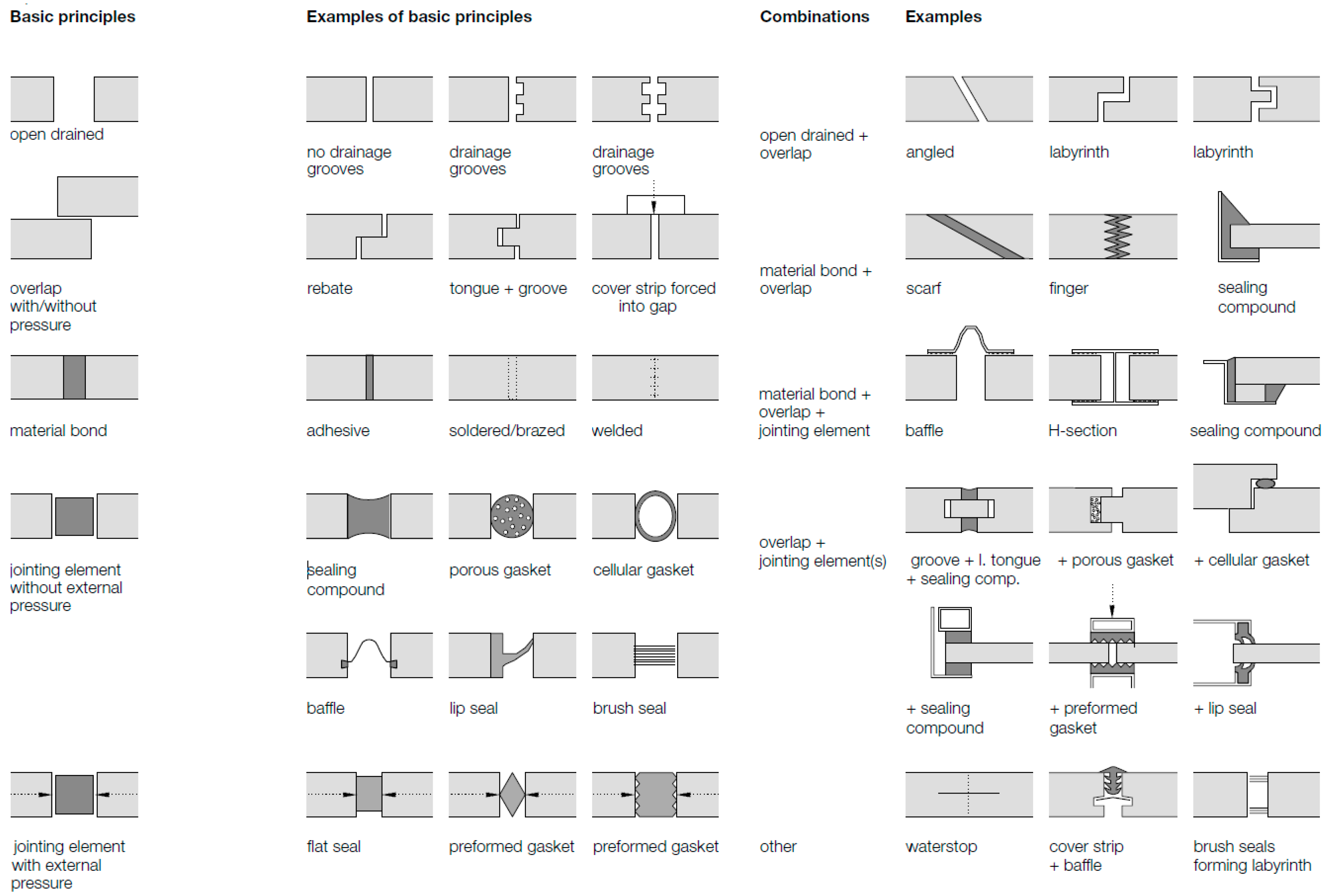
A complete and comprehensive collection of joint design is found in the ‘Façade Construction Manual’ by Herzog [
31].
Figure 7 displays the collection of possible joint design, such material offers great inspiration for design and development of waterproof seals.
It may be interesting to note that
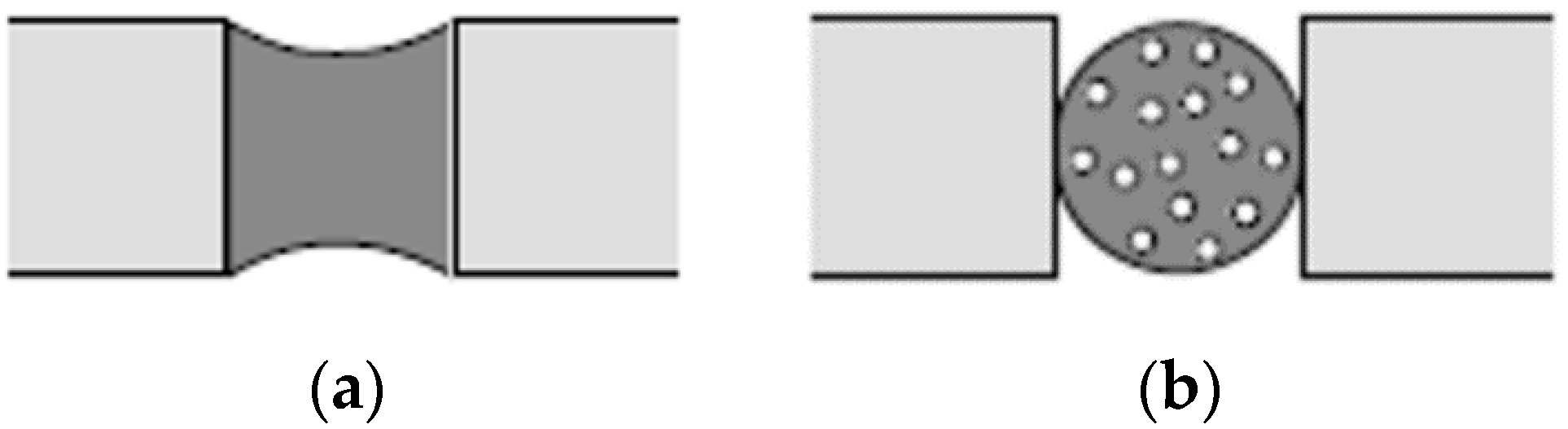
Figure 7 has a vastly comprehensive assortment of sealing principles yet on first appearance conventional solution is not present however on closer analysis the conventional solution of foam backing rod and caulking makes perfect use of two principles outlines in the ‘Façade Construction Manuals’ overview of sealing joints. These are shown enlarged below in
Figure 8, the sealing compound which is the caulking and porous gasket which is the foam backing rod of the conventional solution respectively. The analysis of this has drawn understanding and learning which will be applied in the conceptualisation stages of the design and development of a new seal, specifically it has shown that one does not need to limit their design to make use of just one joint sealing principle, in fact advanced solutions may work on the principles of two or more principles in tandem.
6. Design Objective
In designing a new solution it is recommended that even at the conceptual stage thought should be placed upon how the final outcome must perform. Defining all the certainties and restraints early on narrows the scope and helps provide a boundary in which to build a solution. One such certainty that can be made to practically all projects is that the new design must meet the relevant codes and standards. For Australia the relevant standard is called ‘AS4284: Testing of Building Facades’, it primarily compromises of three tests on a representative sample section of a façade.
The first of which is the Air Infiltration test. This involves testing of the façade with both negative and positive pressure of −150 Pa and +150 Pa respectfully, the air leakage rate for all air-conditioned buildings should not exceed 1.6 L/m
2·s and 8.0 L/m
2·s for all non-air-conditioned building [
31].
The second test is the static pressure test where a static pressure of magnitude 300 Pa and 0.3 Ws (where Ws is the designed wind pressure) whichever the greater will be used with water sprayed to the external face of not less than 0.05 L/m2·s. The first 5 min will be water sprayed with zero applied pressure, then 15 min of water sprayed with the applied pressure then a final 5 min of water sprayed without the applied pressure, during this time observations are to be made from the internal face and any water ingress and damage is to be recorded.
The final test is the dynamic pressure test which is to be performed after successful completion of the static pressure test. In each stage the pressure cycles between the designated pressures as described in
Table 2, the full details are outline in the standard.
7. Lessons Learnt from Past Solutions
In designing new waterproof seals much can be learnt from the challenges encountered in creating past solutions. Tackling the weak areas that is the points and methods of failure right at the early design stage many problems can be avoided down the track.
Experts with considerable experience in facades note that there are a number of weak areas and conditions which should be kept in mind when designing a solution [
32]. Some of the most prominent points of interests to consider have found to be as follows: The joints between the walls and floor, deformation of the building because of applied and dead loads, manufacturing, production and assembly related tolerances, dynamic, horizontal floor displacements caused by wind pressure/suction or seismic actions, changes of length due to differing materials and temperatures and finally water penetration through wind driven rain causing pressure on the surface where surface tension and capillary effected water seeps through narrow joints [
33]. These areas will be particularly considered in the design and development of new sealing solutions.
8. Define Development Need, Objective, Scope and Industry Motivation
In developing a new product a clear and verified need is required to justify one such development.
The need in the case of mid-rise prefabricated construction lies in the fact that conventional means of water proofing are being used in a method of construction which nature is profoundly different. Quicker and less labour intensive solutions which ideally do not require the use of scaffolding for installation or even access from the external face at all would greatly benefit this form of construction. This need has been verified with industry partners who are working in collaboration on this project. Modern prefabricated construction systems do not require scaffolding for assembly of the structure and the erection time is so fast that the time spent waterproofing on site is similar to the time spent to install the entire structure on site.
Systems of weatherproofing which allow the seals to be constructed in a factory instead of onsite generally perform better due to the increased quality control, surface preparation and cleaning and closer supervisions of the sealing process [
33].
Clear and measurable objectives are required not just for evaluation purposes but also aid in creating a solution driven design.
The objectives placed for this design and development are as follows:
To be installed without the use of scaffolding, cranes, overhanging harnesses. Simply put the seal is not installed from the external face by any means
To consume less time than the convention means of foam backing rod and caulking
To be less dependent on skilled labour and human workmanship then conventional means
To be made versatile so as to work with many different structural forms of façades
To meet AS4284: Testing of Building Facades requirements
The overall goal of this research is to deliver a verified sealing solution specific for waterproofing between prefabricated panels/modules. This solution is to be surpass the conventional means in a number of ways such as: Ease of assembly/installation, required access for installation, time and labour required. The focus of this project is to develop such a solution, understand, model and verify its performance in waterproofing in conditions as outlined in AS4284 (2006), specifically against the ingress of water under static pressure conditions and the ingress of water under dynamic pressure conditions. Thus the scope of this project is limited to the development of a novel seal which is better suited for panelised prefabricated construction which meets the aforementioned performance aspects of waterproofing.
Mid-Rise Prefabricated timber construction has had a major increase of support with the Australian new deem to satisfy (DTS) regulations allowing for timber based structures as outlined in the National Construction Code (NCC) to go up to 25 m through a DTS approach. This has caused timber based prefabrication companies to look at higher levels of construction and in this a need for more appropriate sealing solutions.
The developer of any project above 2 or 3 levels constructed in complete panelised or modular form with the whole façade already affixed has a great opportunity to save on cost and time if a new method of weatherproofing is developed. This is because with these complete prefabricated systems where the façade is also preassembled and fixed to the structure prior to lifting, the need for scaffolding and hence external access can be removed entirely if they have a novel connection system which can be operated from within the buildings floor area and if waterproofing the façade and joints between panel to panel or module to module at the exterior face can be done in an unconventional manner from within the building envelope.
The former point (connections) has been developed by industry members in their own manner which have resulted in a number of tightly held patents and papers such as ‘Connections for steel–timber hybrid prefabricated buildings. Part II: Innovative modular structures’ [
34], the latter point (weatherproofing) is still widely done by conventional means and is not yet outlined or studied in literature.
Thus the primary requirement for an ideal solution to waterproofing in these types of mid-rise prefabricated construction is if the waterproofing can be done without the need to be outside the building envelop, that is to have a midrise project without the need for any scaffolding at all.
This first of all is the most major cost advantage and will also directly save time, apart from this restriction on installation other notable desirable requirements are ease and speed of installation so as not to delay lifting and robustness to perform in a satisfactory manner over a range of possible tolerance stacks which timber based panelised prefabricated construction systems have from manufacturing to installation.
9. Outline Design Criteria
The full possible design criteria for waterproof and weatherproof seals and their influencing factors are needed to be identified and be inclusive of specific requirements for use in panelized and modular forms of construction in order to have a feel for the domain of consideration. These will now be outlined.
External conditions; UV radiation—leading to potential change in colour over time and potential change of stiffness over time, Temperature and temperature change—not to degrade under heat and not to change shape under heat, Humidity and humidity change, Rainfall, Wind pressure, Combined action of wind and rain (wind driven rain), Potential dust, dirt and grime, Chemical resistance—Air pollution and cleaning products.
Internal conditions; Suction pressure, Temperature (condensation risk), Air tightness (not permeable to air), Water tightness (not permeable to water), Ability to relieve vapour pressure, Sound transmission—Airborne sound and Structure-borne sounds.
Interaction between External and Internal conditions; Pressure and suction pressure combination, Tolerances—Production, Erection/Assembly, Deflection of components, Bowing, Creep, Tolerance stack up (the sum of tolerances), Allow air to enter/escape (ventilation), Prevent the condensation of water, Capillary water movement, Allow for differential movements—Deflections before, during and after installation, Long term creep, Dynamic movements, Expansion and shrinkage movements, Horizontal and vertical joints and their movements externally with their relation internally and vice-versa, Force transfer—element by element and supporting construction element, Allow drainage of runoff and infiltrated water, Allow/block passage of light and protection against frost damage (non-absorbing material).
Other; Mass customization and versatility, in order to be a viable solution for many projects and not a one off solution, Allow relative movements—Tolerance, wall displacement further apart (gap larger and smaller), Tolerance, wall displacement out of plane (walls not lining up exactly, one slightly forward and one slightly backwards), compensation for tolerances: Manufacturing tolerances, erection tolerances, movement tolerances, Transportation to site—Damage resistance to abrasion, Damage resistance to impacts (rocks), Assembly—handling not to cause damage and ease of installation, Service life of the building—Design life, Maintenance required and ease of maintenance and susceptibility to insect and bird attack.
10. Method Overview
Once the design and development can be justified as per the process previously displayed in
Figure 1 an explored thereafter the design and development can take place. A high level overview from the justified position of required design and development is displayed in
Figure 9. This starts with design and ending with a continuous loop of monitoring and evaluation, verification and tailored manufacturing. From the design stage (expanded upon in
Figure 10) comes the development stage (expanded upon in
Figure 11), after the development stage a model (may be physical or digital) of the generated proposed solution is created, evaluation is next conducted and iteratively cycled back to the design stage until the decision is made to proceed to sample manufacturing, form here small scale and large scale testing can be conducted on a representative manufactured prototype, further refinement may be made to the design, once refined further manufacturing can take place, full scale testing which may not of been possible with sample manufacturing may now take place, a successful result leads to full scale manufacturing and adoption to projects to which are monitored and evaluated with learnings continuously incorporated back to the design and the development processes.
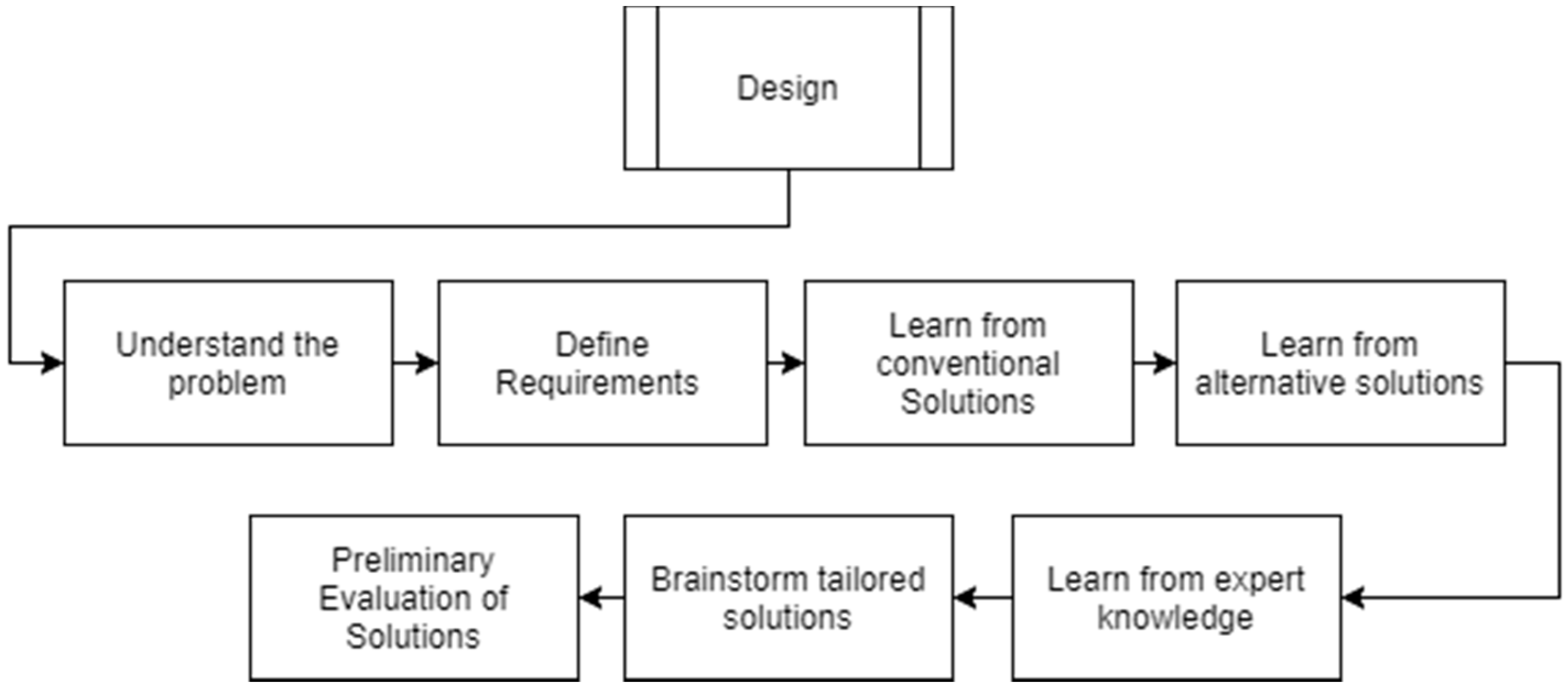
11. Design Process
The design process used in this project is a 7 step method as illustrated in
Figure 10 below.
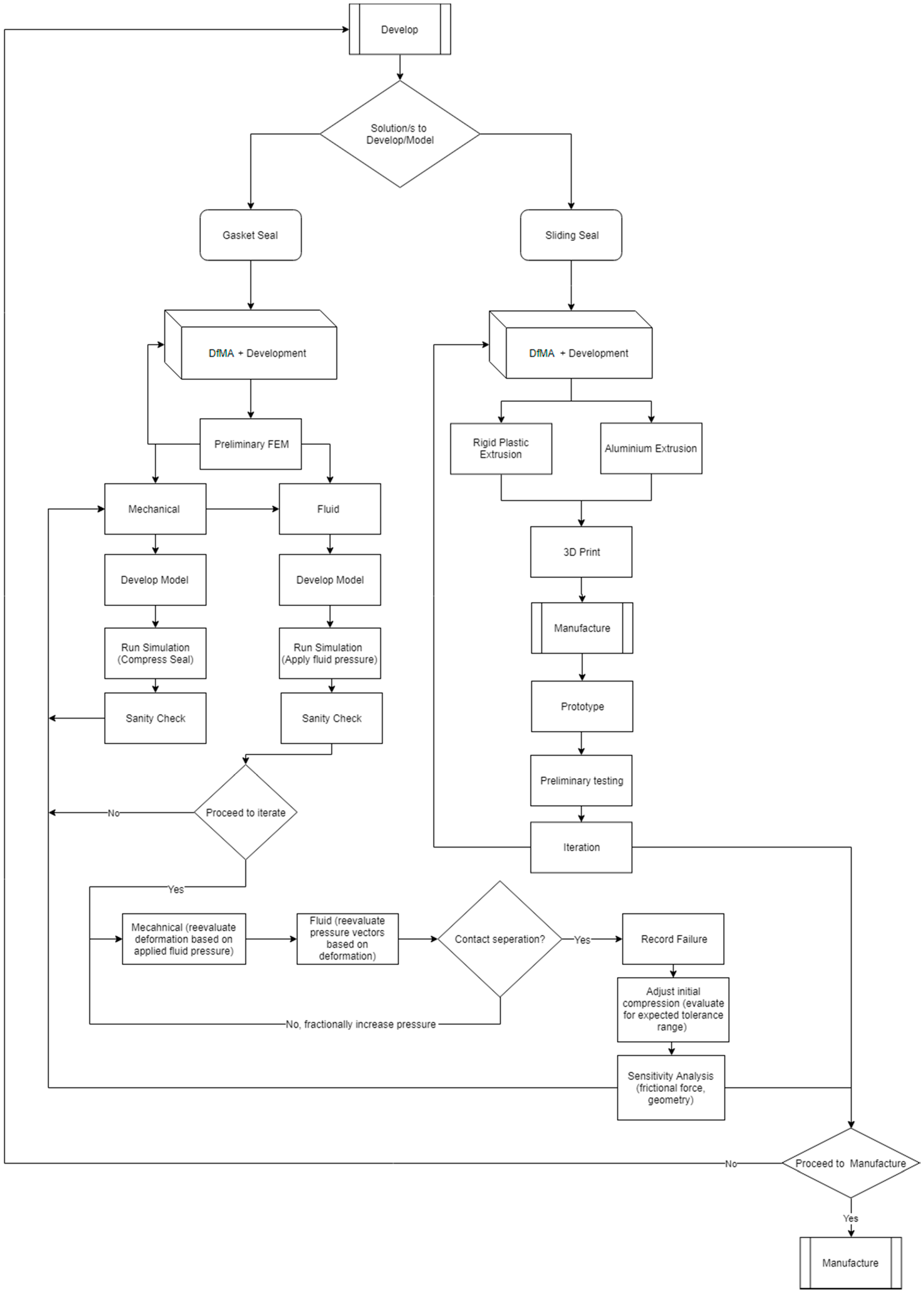
12. Development Process
The development process is the most crucial and intricate part of the project,
Figure 11 outlines this in detail. As a foundation to the development process a robust design process must first be completed which resulted in the preliminary evaluation of potential solutions. To move to the Development stage selection of one or two of these potential solutions must be made to develop upon. In this case a solution which is in the form of a gasket seal which installed prior to the wall being sent out to the factory and inherently compressed during installation of the wall through appropriate connection and the sheer weight of the wall as it is craned into place has been chosen as a potential solution to develop. Another potential solution is of a multi-component nature in which a carefully design rigid plastic extrusion is slid down from above into a railing of an aluminium extrusion. Both potential solutions will be discussed later in further detail.
After choosing the potential solutions DfMA and development principles and processes as per
Figure 12 are then adopted, these form the fundamental key in the overall development of a successful practical solution which can be implemented whilst minimizing the unexpected difficulties.
From here tailored solution specific steps follow, the examples given of the rubber gasket seal and the rigid plastic sliding seal have entirely different strategies of development which have purposefully chosen to best meet the practicalities of their respective solutions and to offer a comparison of approaches. The two processes for development proposed is a rapid prototyping and iterative testing and refinement strategy for the sliding seal and a computational design strategy for the rubber gasket seal. Both these strategies are valid and serve their purpose well when paired with the correct proposed solution. The computational design strategy as shown in
Figure 11 after the DfMA block for the gasket seal was chosen due to the range of compressibility that the material undergoes to form a water proof seal. This means that once the properties of the rubber material are established a variety of geometries and levels of compression can be modeled via mechanical finite element software for the deformation shape and reactionary forces. The strategy the gasket employs in resisting water pressure is that of a physical barrier which is complete by the desired expansion of the compressed rubber. This expansion is in the range of approximately 5 mm for the gasket developed thus manufacturing tolerances is not a primary concern. A fluid dynamic model can then be prepared on the basis of the deformed shape and hence a water pressure applied, this pressure can be increased until such a stage in the model where the fluid causes the reactionary force of the rubber gasket to the opposite side of the wall to drop to zero, so a clear strategy in this model can be executed. Furthermore, the gasket seal comes in the form which is rolled up and has an adhered adhesive tape on the back which can be peeled off and then applied to the end of the wall in the factory thus negating much of the concerns about installation and fitment. Therefore, since the primary concern and interest is the desired stiffness and geometry a computational approach was most appropriate as it satisfies these concerns and provides an efficient means to confident manufacturing. As for the rigid plastic sliding seal, rapid prototyping, testing and iteration is by far the more appropriate development method as not only an accurate computational method difficult to achieve for waterproofing with such small levels of deformation the very principle of the design is that it allows for water to pass its point of contact and drain down the joint as the sealing principle is entire different, with the gasket solution it was a physical barrier and with the sliding seal it is a drained protection. After eliminating a computational strategy for this proposed solution a rapid prototyping one is chosen. This is not just because of ruling out a computational solution but also because of concerns over the design and functionality of the potential solution in from concept to installation. For example one concern is the manufacturing capabilities of plastic extruders to form complex dies and tight extrusions which are uniform and with minimal variation, another concern is the flexural rigidity and shape of the extrusion profile together with the material selection and finally another major concern is the installation, although it can be done from within the footprint of the building and not require scaffolding there may be the potential issue of the extrusion developing a kink if it gets snagged on a damage aluminium railing and or due to an excesses of applied force potentially due to the level of friction is may experience as it gets installed. These concerns lend to the rapid prototyping development as outlined under the DfMA block for the sliding seal in
Figure 12. The early involvement of manufacturers along with getting a hands-on feel with a variety of samples of their extrusion from past and current runs results in a much more realistic appreciation for the task at hand and firmer position on the eventual solution which would conform with the tolerances and capabilities. With this understanding along with the fact that the material in question is rigid-plastics 3D-printing work can be done on proposed geometries which can be evaluated. This strategy can lead to confidence in making the financial commitment to tooling a custom die and running extrusions noting that a geometry should be selected such that the rigidity of the plastic may be used as the mechanism for softening or stiffening the fingers of the sliding seal or at the least further refinement of the existing die by cutting away more material but not visa-versa. The goal of development is manufacture and it is been shown that for this application not one specific set of process is to be taken but rather a general set which is then tailored to best satisfy the inherit properties of the proposed solution and the concerns and unknowns behind it.
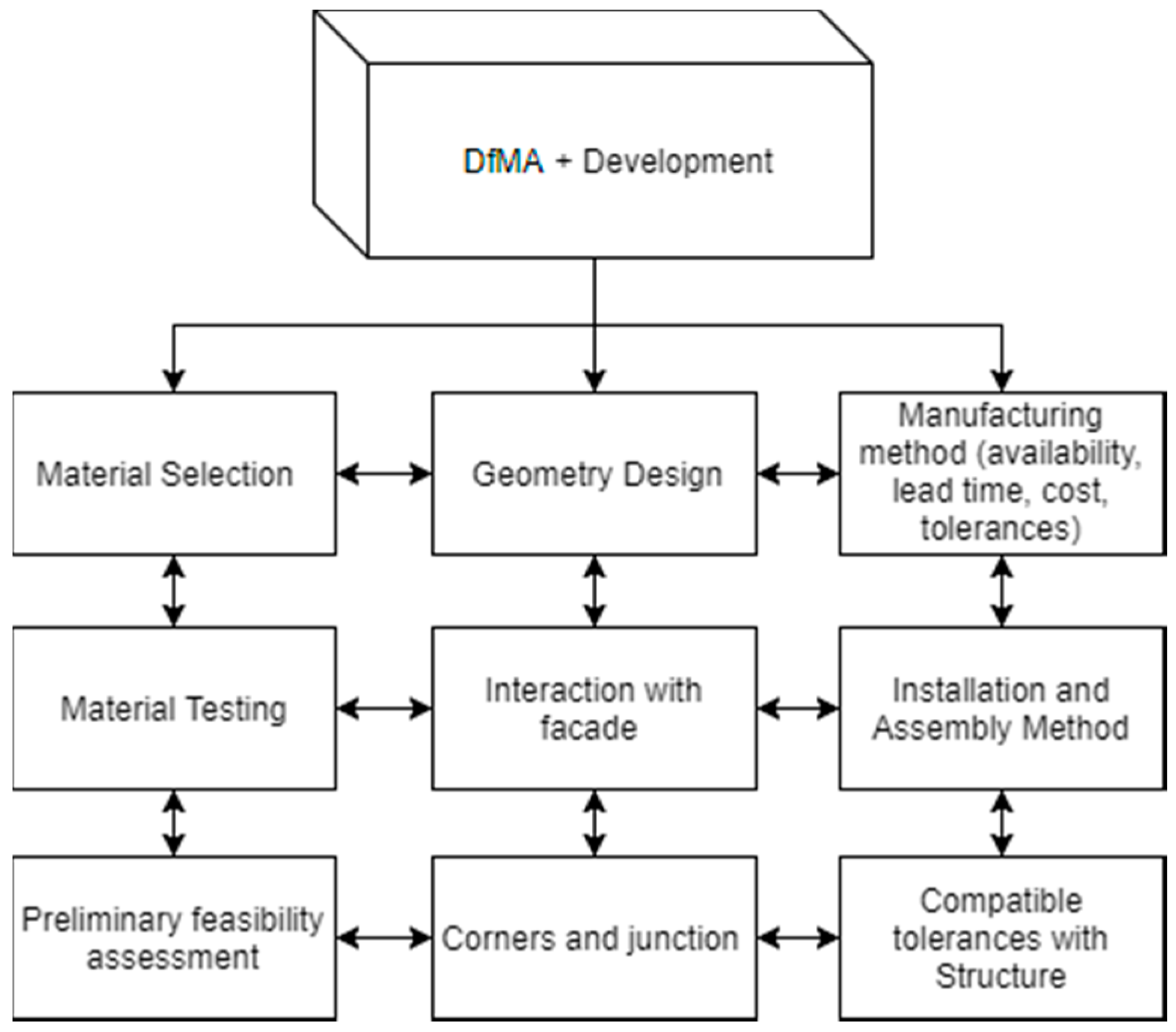
13. DfMA and Development Process
The Design for Manufacture and Assembly (DfMA) and Development process for this project lies wholly within the development process and additionally incorporates some notions of development, hence the pairing as outlined in
Figure 12.
14. Proposed Design Solutions
Two prominent methods of sealing have been devised to firstly meet the most optimal criteria of working solely within the building envelope, the sealing solutions for between panels/modules are a compressed rubber gasket and a rigid plastic extrusion sliding seal solution.
14.1. Gasket Solution
The schematic of joint sealing principles as shown previously in
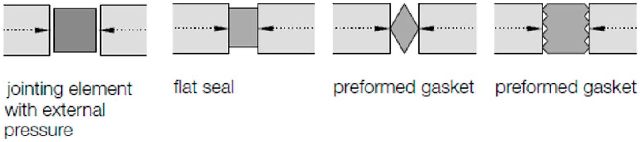
Figure 7 provides an excellent comprehensive assortment of examples of all the principles which have or can be used in sealing of joints. One type of which caught great interest for the purposes of panelised construction was that of gasket seals or ‘jointing element’ which will compress under in plane loading as the resultant pressure to act as a physical barrier to water penetration as shown in
Figure 13 below.
The reasons which these types of seals principles drew fascination was due to their potential suitability to for a specifically designed seal in between panels in prefabricated panelised construction was firstly that the compressive force can be naturally applied through the pFilacement of the wall panels during placement onto the supporting connections. Secondly if compressed enough to which is not an issue as the mass of a timber based panels of truck length can easily be over 1 tonne then the seal would be able to absorb the range of in plane tolerances which is typically experienced. Thirdly and finally the gasket solution was envisioned to be able to be pre-installed onto the wall panel making for an extremely efficient on-site installation to which is of great importance to this form of construction and is also the primary identified objective and differentiating factor with the conventional solution.
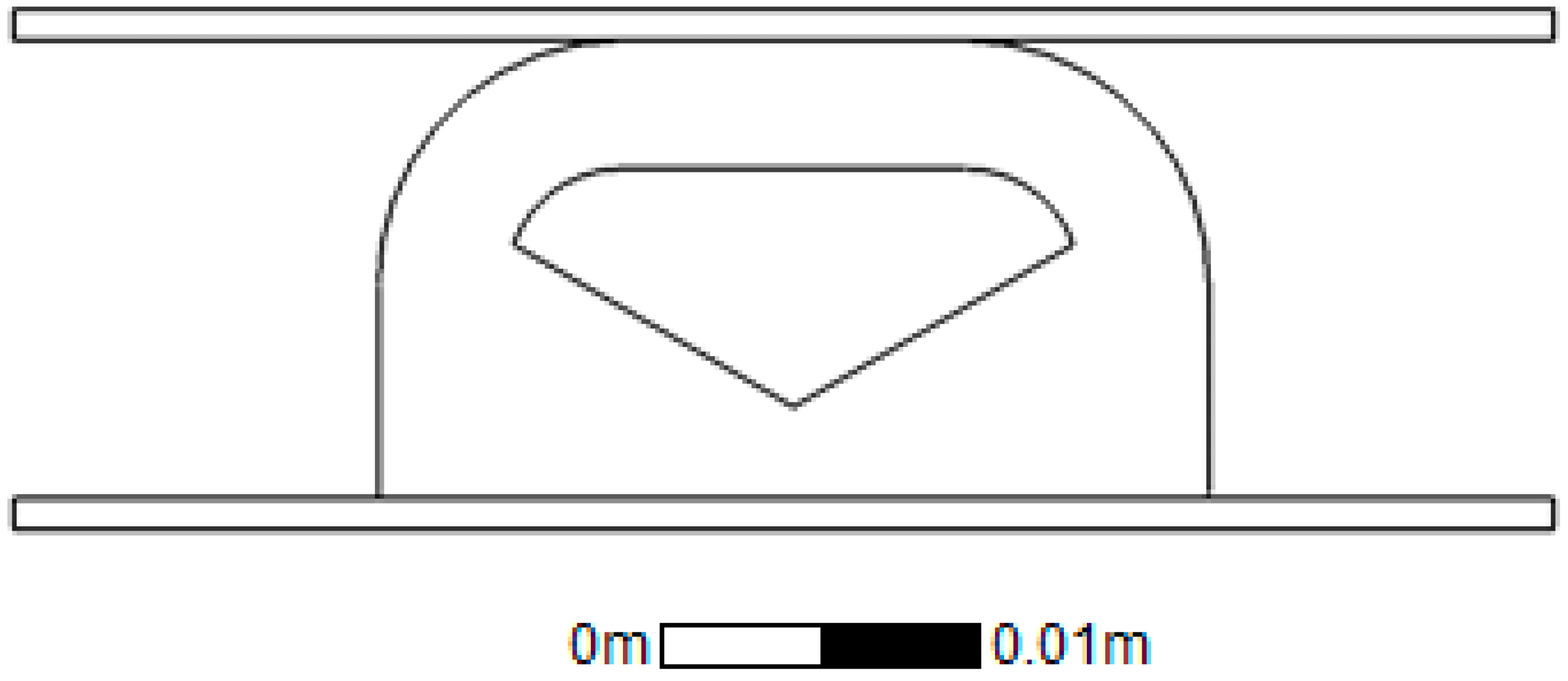
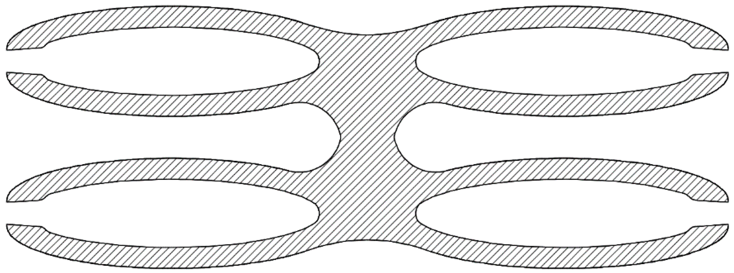
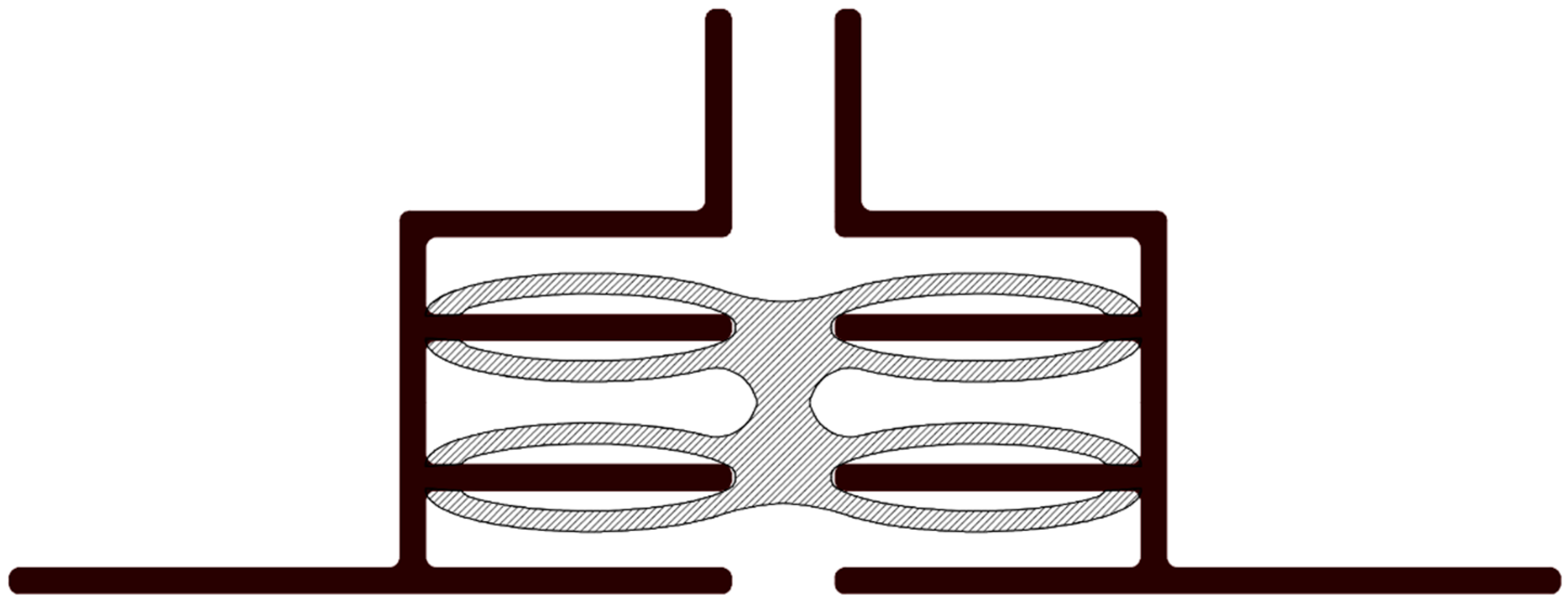
The gasket solution developed as shown above in
Figure 14 compromises of a specially designed rubber extrusion profile whole one side is flat allowing for a dual face adhesive tape to be applied during the manufacture of the extrusion and an aluminium extrusion which houses the façade panel and frames the end of the timber panelised element. The opposite face is curved to allow for out of plane movements and to help the gasket not to get caught and ripped during handling or installation, with in between a carefully designed void. The void is such that that the centre has more material cut out allowing for dual high pressure zone on the exterior and interior face respectively once compressed. Apart from providing a double barrier effect this also increases the stability of the seal when placed under shear loads which are highly expected when the panel is lowered into place from the adjacent panel.
The extruded rubber is made from ethylene propylene diene monomer (EPDM) and has the double-sided tape applied to the flat face and then coiled up into long lengths before delivery to the prefabrication factory.
Once delivered at the panel/module prefabrication factory the seal can be affixed to the end of the panel by simply peeling off the backing tape and sticking the seal to the clean outer flat face of the aluminium extrusion and then applied all the way up or down and then cutting to length, alternatively the seal can be cut to length prior to adhesion onto the aluminium extrusion which may make handling easier however it introduces an extra step of measurement.
If handling and transport damage is a concern, particularly with tying panels together for either of these tasks then the seal can simply be applied on site when the truck arrives however the aluminium surface will need to be checked for damage and cleaned before affixing the seal. Another matter to recognise is the introduction of another task on site which may or not be on the critical path dependent on the logistics and delivery although the risk of unwarranted damage of the seal is mitigated. The gasket is to be installed on the outside edge of the panel and thus act as a waterproof barrier which is installed prior to wall placement and thus requires no on site work and most importantly no on site work which would require access from the external face however from the internal side the design gap can be filled with an expandable foam, rock wool insulation or any other insulating materials to minimize the effects of thermal conductivity of the building components in heat transfer which allows the solution and the building to be versatile in a variety of climate conditions [
35]. Lastly the EPDM D-Seal gasket can absorb a wide range of tolerances comfortably due to its highly flexible nature thus a physical assumption is the prefabricated elements stay within these range of design tolerances however if the gap notably larger than expected then there may not be adequate compression of the seal and a larger dimensioned gasket must be used.
14.2. Sliding Seal Solution
The schematic of joint sealing principles uncovered in the literature review as shown previously in
Figure 7 which provides an excellent comprehensive assortment of examples of all the principles which have or can be used in sealing of joints has again been used in the conceptualisation phase of designing and development new waterproof seals specifically suited for panelised prefabricated construction.
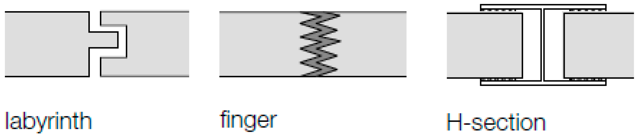
The labyrinth seal principle acts as a method to aid in waterproofing as it creates a difficult path for the water to travel due to the sharp right angles. This principle coupled with the finger principle in which greatly lengthens the water ingress path was figured as an interesting design option especially when coupled with the theory of drained protection as presented prior in 6 water proofing theory as it is easier to slow the path of water and drain it than to stop it entirely, this would additionally be suitable for timber based systems as it provides a level of breathability. The H-section principles as depicted in
Figure 15 works through the merging of two planer elements typically glass however it was figured that perhaps instead of glass and instead of merging it was a smooth aluminium extrusion profile which provided the guide for a rigid plastic extrusion to slide down.
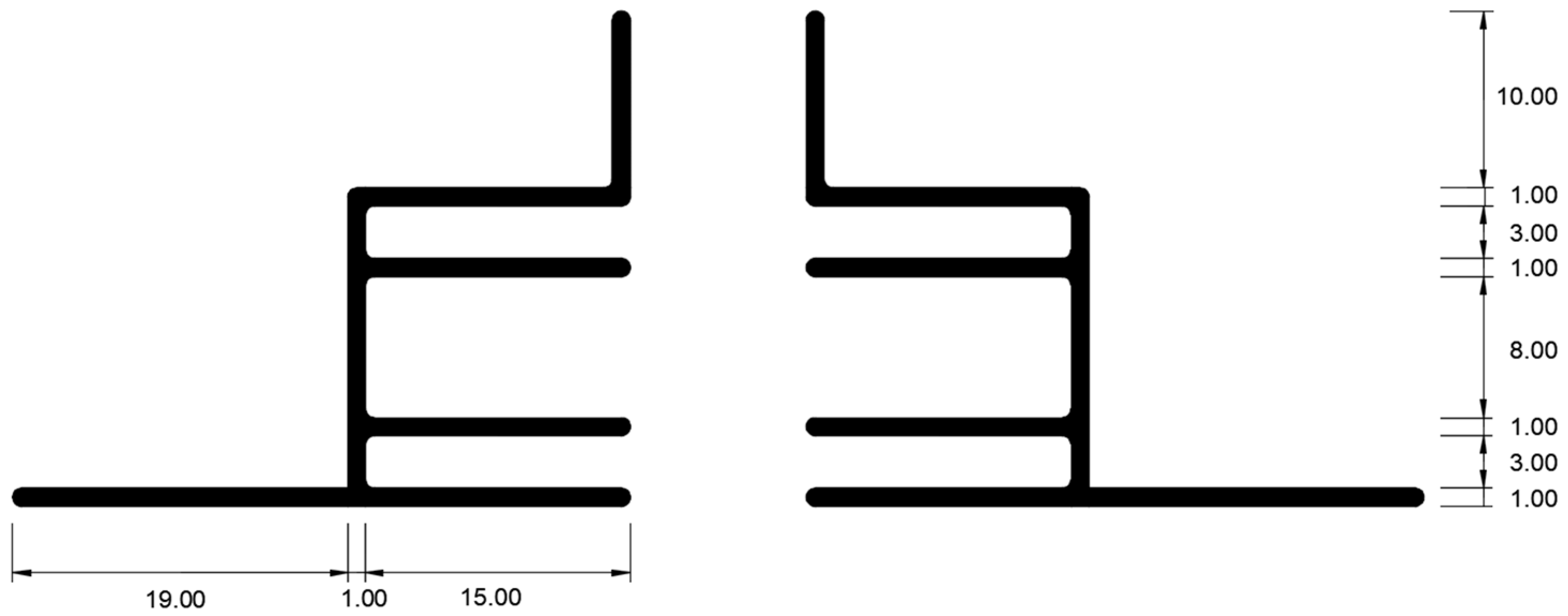
An intricate aluminium extrusion (as shown in
Figure 16) has been designed such that the aluminium extrusion will house the façade panel, frame the outside edge of the wall, aligned the facade baton, nailed into the timber stud behind and when faced back to back with an adjacent wall panel at a nominal gap of 10 mm provide a smooth track for the rigid plastic extrusion to slide down. A specially designed sliding seal made from a rigid extruded plastic (as shown in
Figure 17) is such that it applies an appropriate amount of pressure to the aluminium extrusion. Enough so that firm contact is made throughout the length but not too much which makes the seal too hard to slide down by an individual worker or apply too much pressure so that it would be so hard to slide down such that the worker must exert a force capable of buckling the section at a distance comfortable for repeated movements from a stationary bent position. The sliding of the seal can be done simultaneously and out of the way while another wall if being lifted into place so as long that all the walls in each level have been completed prior to moving to the next level, this along with the fact that the installation process can be purely done from within the buildings envelop offers great advantages in terms of speed of construction and cost as compared to the conventional solution.
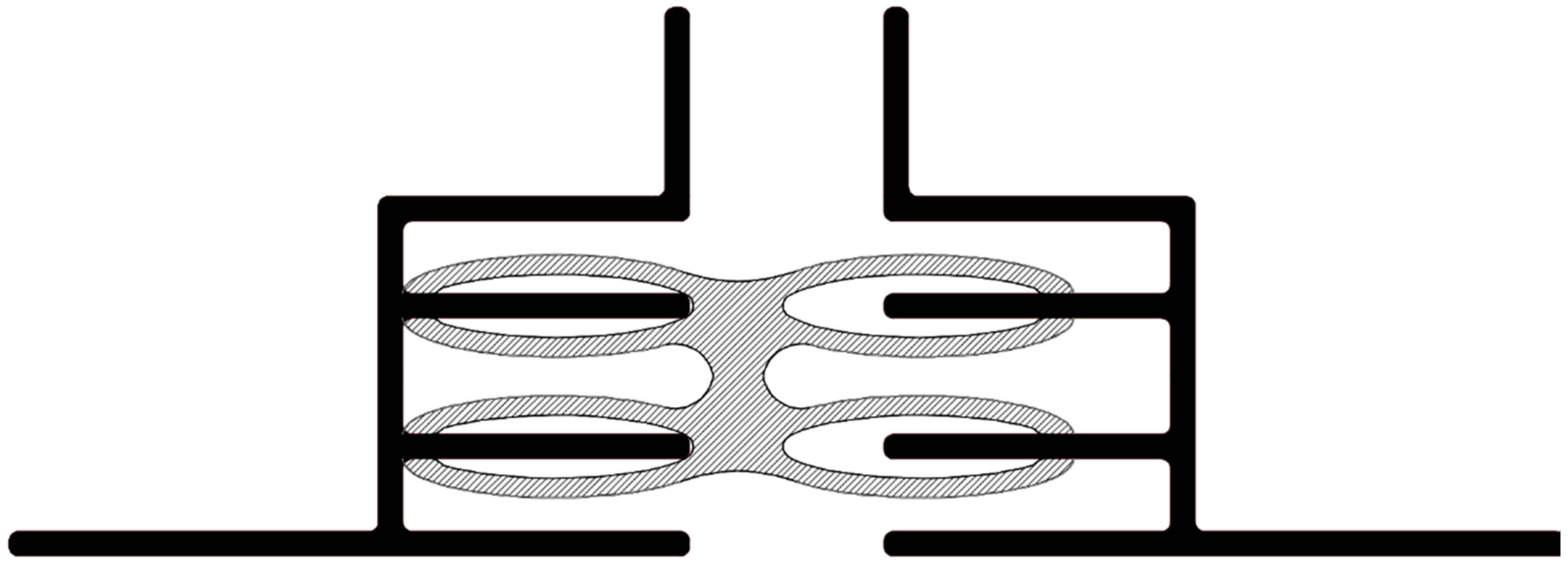
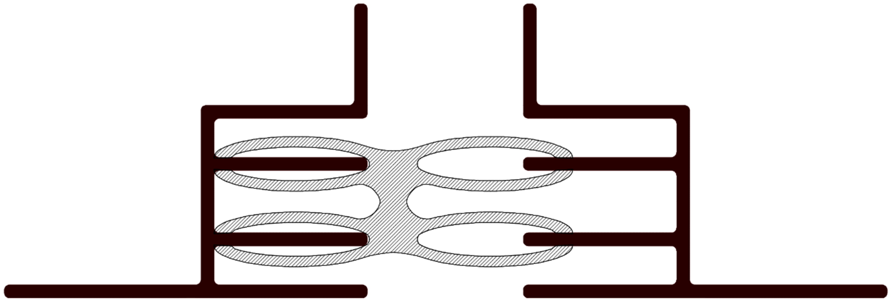
Figure 18,
Figure 19 and
Figure 20 show the flexibility of the seal to handle wide range of worst case in plane tolerances, in addition to this there is also flexibility in handling of out of plane tolerances too as indicated by the gap between the top and bottom external faces of the seal with the aluminium extrusion. This gap can be filled from the internal face with insulating materials to minimize the effects of thermal conductivity of the building components in heat transfer which allows the solution and the building to be versatile in a variety of climate conditions.
A key physical assumption which relates to the performance of the seal is that the geometry of the extrusions is to be accurate to that of the design, this is especially important for this solution for both the aluminum extrusion and the rigid plastic extrusion due to the complex geometry and hence complex manufacturing. Furthermore if the walls are outside the design tolerances of plus and minus 5 mm the prefabricated elements will simply be too close together or too far apart for this solution will not work in its current configuration. To address the circumstance of experiencing tolerances outside that which have been designed for the regular backing rod and caulking still can be applied as a failsafe otherwise extrusions of a larger and smaller dimension can be made for use if the construction ever exceeds the design tolerances.
Other than the direct pressure between elements the manner in which the waterproofing is made comes down to the path in which the water must take to reach the interior of the wall. It is with a labyrinth design that the rigid plastic and aluminium extrusions hinder the capability for wind driving rain to penetrate whist also allowing for a drainage path for any water which does happen to past the outer layer of protection.
Additionally, the principle of pressure equalization also aids in preventing water ingress. The pressure equalization works by utilization of an air barrier which is formed between the interior backing wall and the external cladding and having this region of space ventilated. As long as the interior backing wall is impermeable to air flow and the cavity region is free to ventilate and normalise air pressure to that of the external face then the pressure differential through the cladding is minimised. This means that the pull force or suction force onto the water is mitigated, although having the correct amount and shape of gaps to ensure ventilation (including weep holes) but not to allow significant direct water penetration is a key balance which needs to be made.
15. Conclusions
Waterproofing sealing methods of joints commonly practiced have served well in conventional construction however with many prefabricated systems emerging in the building industry new and novel means of weatherproofing between panels and modules need to be developed purpose specific to this application. The methodological approach proposed for the design and development of the waterproof sealing of joints in prefabricated construction has been thoroughly explored and has resulted in identifying, understanding overcoming the technical challenges of an ideal solution such as installation without access from the exterior face of the building and satisfying building tolerances. Flow charts have been used to convey the overview and the processes within which include DfMA principle being incorporated into understanding and developing seals specifically for panelized and modular forms of prefabricated construction, particularly the vertical joints between fully completed assemblies. Two purpose developed weatherproof sealing solutions has been proposed specific for prefabricated panelised and modular systems which have incorporated design criteria which are encompassing of the entire design, manufacturing and assembly processes. These strategies have enabled the development a resourceful and holistic set of processes which are tailored for the proposed solutions and can be adapted and used for similar forms of product research particularly in the design and development of waterproof seals for joints between panels and modules in prefabricated construction.


