Article

Nonlinear Modelling of Curved Masonry Structures after Seismic Retrofit through FRP Reinforcing

1
Department of Civil Engineering and Architecture, University of Catania, 95125 Catania, Italy
2
Department of Civil Engineering, Institute for Sustainability and Innovation in Structural Engineering (ISISE), University of Minho, Azurem, 4800-058 Guimarães, Portugal
*
Author to whom correspondence should be addressed.
Buildings 2017, 7(3), 79; https://doi.org/10.3390/buildings7030079
Submission received: 24 April 2017 / Revised: 19 August 2017 / Accepted: 21 August 2017 / Published: 29 August 2017
(This article belongs to the Special Issue Traditional and Innovative Approaches in Seismic Design)

Abstract

:
A reliable numerical evaluation of the nonlinear behaviour of historical masonry structures, before and after a seismic retrofitting, is a fundamental issue in the design of the structural retrofitting. Many strengthening techniques have been introduced aimed at improving the structural performance of existing structures that, if properly designed and applied, provide an effective contribution to the preservation of their cultural value. Among these strategies, the use of fabric-reinforced polymeric (FRP) materials on masonry surface is being widely adopted for practical engineering purposes. The application of strips or 2D grid composite layers is a low invasive and easy to apply retrofitting strategy, that is able to improve both the in-plane and the out of plane behaviour of masonry elements also in the presence of complex geometries thanks to their flexibility. For this reason, these techniques are frequently employed for reinforcing masonry curved elements, such as arches and vaults. In this paper, taking advantage of an existing general framework based on a discrete element approach previously introduced by the authors, a discrete element conceived for modelling the interaction between masonry and FRP reinforcement is applied to different curved masonry vaults typologies. This model, already used for evaluating the nonlinear behaviour of masonry arches, is here employed for the first time to evaluate the effectiveness of FRP reinforcements on double curvature elements. After a theoretical description of the proposed strategy, two applications relative to an arch and a dome, subjected to seismic loads, with different reinforced conditions, are presented. The benefit provided by the application of FRP strips is also compared with that associated to traditional retrofitting techniques. A sensitivity study is performed with respect to the structure scale factor.

1. Introduction

The numerical simulation of the seismic response of historical masonry structures (HMS) is a key aspect of the cultural heritage preservation, and represents a challenging issue within the structural and earthquake engineering. Historical masonry structures represent a high percentage of existing buildings in several regions of the world, and their value is relevant both from the economic and social-cultural points of view. On the contrary, they suffer from scattered structural degradation, due to static loads, chemical and physic degradation of the materials, previous earthquakes, and wrong alterations of the original structural conception. Normally, they are not able to resist to earthquakes even if characterized by a low intensity. Recent seismic events occurred in Italy, such as the Central Italy Eartkquakes (2016), the Emilia (2012), and L’Aquila (2009); they produced severe damage patterns or the complete destruction of several historical sites. Such events, well documented in terms of post earthquake technical survey, demonstrated many critical aspects, which make vulnerable the historical structures to the horizontal and vertical seismic actions. One of the most important aspects is the presence of elements with a curved geometry such as arches and vaults, which interact with the vertical elements (walls or columns) during the earthquake motion, producing a significant effect on the seismic response of the entire structure.
Curved structures have been widely adopted in the past for building purposes, since their shape allows an effective transfer of the static vertical action to the walls, and induces compression along their span; for the latter reason curved shapes are still adopted and proposed for modern structures [1,2]. When it comes to single and double curvature masonry structures, their study is still an open problem debated in the literature [3]. Aimed at the reduction of the seismic vulnerability of HMS in presence of curved masonry elements, several retrofitting techniques based on reinforced composite materials, applied by means of polymeric (FRP) or cementitious (FRCM) matrix, have been introduced, and widely investigated by means of experimental tests and numerical simulations during the last years. The use of these techniques is getting more and more frequent in the retrofitting of historical and monumental masonry buildings since they consist of reversible and low invasive interventions; with regard to the design of FRP reinforcements, several proposals have been made [4,5]. On the other hand, there is a lack of fast and reliable numerical tools to assess the effectiveness of such techniques.
In fact, even considering unreinforced masonry structures, the numerical simulation of their actual behaviour is still a very complex task within the computational structural mechanics field. The main issue is related to the difficulty in providing reliable simulations of the high nonlinear degrading cyclic response of masonry. To this regard, a great variability of the mechanical characteristics is encountered, thus making difficult the definition of a general constitutive law that is suitable for all masonry typologies. When it comes to retrofitting techniques, and in particular to fibre-composite strengthened structures, a crucial aspect is related to the correct simulation of the tangential stress transferred from the reinforcement to the masonry substrate, and the relative failure collapse for tensile rupture of the textile or delamination of the reinforcement from the support. On this task, several contributions have been given by different authors and now are available in the literature [6,7,8,9], also in presence of curved support [10,11].
Recently, a 3D macro-model has been proposed for the non-linear seismic simulations of masonry structures aiming at a reduced computational effort when compared to the traditional finite element approaches. The main idea of the model was to use a 2D mechanical scheme, governed by unidirectional non-linear links, which, according to different typologies, have to reproduce the main masonry failure modes [12]. Such a model has been successfully employed in the simulation of laboratory tests [13] and in the seismic assessment of ordinary and mixed masonry buildings [14,15,16]. Subsequently, the model has been extended to catch the out-of-plane behaviour of masonry walls [17,18] and the behaviour of structures with a curved geometry [19,20,21].
In this paper this discrete macro-modelling approach is used to assess the seismic capacity of some typologies of masonry vaults commonly present in historical structures, before and after a reinforcing retrofit through composite materials. With this aim, a new non-linear model recently proposed in the literature [22], able to simulate the presence of FRP strips or 2D-webs and to grasp the interaction with the masonry support, also in presence of a curved substrate, is here employed. The model is able to simulate the debonding of the reinforcement from the masonry support due to tangential delamination or to normal tensile detachment, which represent the most probable collapse mechanisms of FRP reinforced structures.
Different strips arrangements applied either to the intrados or to the extrados surfaces are considered in the paper. The efficiency of the FRP retrofitting is compared to the traditional technique of adding steel tie-rods in order to investigate the optimal solutions with respect to the retrofit design and to the use of composite material. The results of the numerical simulations relative to the arches, have been compared with those obtained through limit analysis approach, and applied to simpler models. The analytical results are used to validate the numerical results and are duly discussed providing a contribution towards the understanding of reinforced curved structures subjected to seismic actions. The results show that the composite reinforcements can produce a significant increment of the seismic capacity in terms of both strength and ductility, without increasing the stiffness of the structure. The employed macro-model is able to effectively grasp the behaviour of unreinforced and reinforced (both with traditional and innovative techniques) curved masonry structures, as well as providing reliable results which contribute to the relevant literature towards the optimal design of historical masonry structures retrofit.

2. The Modelling of Historical Masonry Structures

In this work a numerical strategy based on a discrete macro-model, already available in the literature, is employed for the nonlinear numerical simulations of both unreinforced and FRP reinforced masonry structures. According to this approach, the masonry is modelled by an equivalent mechanical scheme, constituted by a hinged quadrilateral endowed with one or two diagonal links to rule the diagonal shear cracking, and interacting with contiguous elements along its four edges by means of nonlinear discrete interfaces which govern the flexional and the sliding behaviour. Each discrete interface is made of a single or multiple (according to the model) rows of transversal links for the flexional behaviour and single or multiple (according to the model) sliding links. The different stages of this discrete element are reported in Figure 1. This approach was originally introduced for modelling the in-plane behaviour of Unreinforced Masonry Structures [12], Figure 1a. This plane element possesses four degrees of freedom, a single row of transversal links and a single in-plane sliding link, and is able to model the main failure mechanisms of the masonry in its own plane, as long as a proper calibration procedure of the links is adopted. Two subsequent upgrades were achieved to expand the potentialities of the approach. First, the out of plane (spatial) behaviour, typical of historical constructions, was added [17,18] by considering additional rows of transversal links, and two additional out-of-plane sliding links (able to govern the out of plane shear behaviour and the torsion), thus enabling the out of plane degrees of freedom, as shown in Figure 1b. Subsequently, a further upgrade was introduced considering a shell macro-element characterized by an irregular geometry, variable thickness along the element, and skew interfaces [19,21] in order to deal with structures with a curved geometry, such as vaults and domes, Figure 1c. The calibration procedures, concerning the mechanical properties of the links, were properly extended in order to account for the more complicated geometry of the element, but keeping the same general philosophy.
Numerical and experimental validations of the proposed approach, with reference to full-scale structures can be found in [23,24]. More recently this approach was also extended to the dynamic context [25].

3. The Modeling of FRP Reinforcing

The extension of the macro-element approach to account for the presence of FRP-reinforcements was proposed in [22], and is here briefly recalled. The presence of the fibre-reinforced elements is modelled by means of zero thickness rigid flat elements, partially or totally lying on one of the surfaces of the masonry element, as shown in Figure 2. A special zero-thickness non-linear interface, whose kinematics is related to the relative displacements between the masonry and reinforcement macro-elements, was introduced to simulate a proper interaction between the FRP element and the masonry support. In particular, the FRP-masonry interface discretization is here performed according to a discrete distribution of nonlinear links whose nonlinear laws account for the presence of the adhesive, organic, or cementitious, matrix by allowing the mutual reinforcement-masonry normal and tangential stresses. In particular, a layer of transversal links is introduced to model a flexural detachment of the textile, while two longitudinal orthogonal links model the crucial aspect of the delamination phenomenon. The calibration of the transversal links is performed according to a bilinear constitutive law (with different compressive and tensile strengths) with a post-elastic branch calibrated according to the relevant compressive and tensile fracture energies. On the other hand, the sliding links are calibrated with a symmetric bilinear law whose post-elastic branch is associated to proper fracture energy, with a dependency of the current strength on the normal action on the interface.
Discrete interfaces made of a single row of links (calibrated according to a fiber discretization approach) rule the constitutive behaviour of the textile itself. This latter aspect, together with the sliding links of the FRP-masonry interface, leads to a progressive transfer of the tangential forces between masonry and FRP reinforcement; thus, implying a numerical definition of the so called anchorage length. In the applications reported in the following, the mechanical properties for the FRP laminates have been assumed according to a simple elasto-fragile law attributed to a homogenous material, with an equivalent thickness (tf), characterized by a Young’s modulus (Ef) and tensile strength (ft), incapable to resist to compression loads. A schematic layout of the modelling approach of a masonry element reinforced with a FRP strip is reported in Figure 2.
Despite its simplicity, the model is able to predict the main collapse mechanisms associated to the reinforcement: the rupture in tensile of the fiber, the shear debonding, and/or the peeling of the reinforcement. Furthermore, mixed failure mechanisms in which the masonry is involved, can be predicted.

4. Retrofitting and Restoration of Curved Masonry Structures by FRP Materials

In this section, the ultimate seismic strength of two typologies of curved structures is numerically simulated before and after a consolidation retrofit. Namely, a circular arch and a spherical dome are considered. A standard technique, that is the application of a tie rod, and an innovative technique, that is the application of FRP strips, are here considered and compared.

4.1. Circular Arch

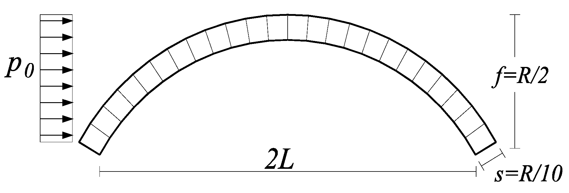
A simple circular arch with radius R is considered in this section; the other significant geometric parameters are inferred as functions of the radius, that is the half bay ( L = R 3 / 2 ), the rise (f = R/2), the thickness (s = R/10) which is kept constant, and the width (b = s). The basic geometry of the arch is characterized by the value R1 = 866 mm, which corresponds to a prototype tested in the laboratory, subjected to an unsymmetrical vertical static load [26]; then, two additional values of the radius (R2 = 1500 mm and R3 = 2500 mm) are considered in order to investigate the effect of the scale factor on the response of the unreinforced and reinforced systems.
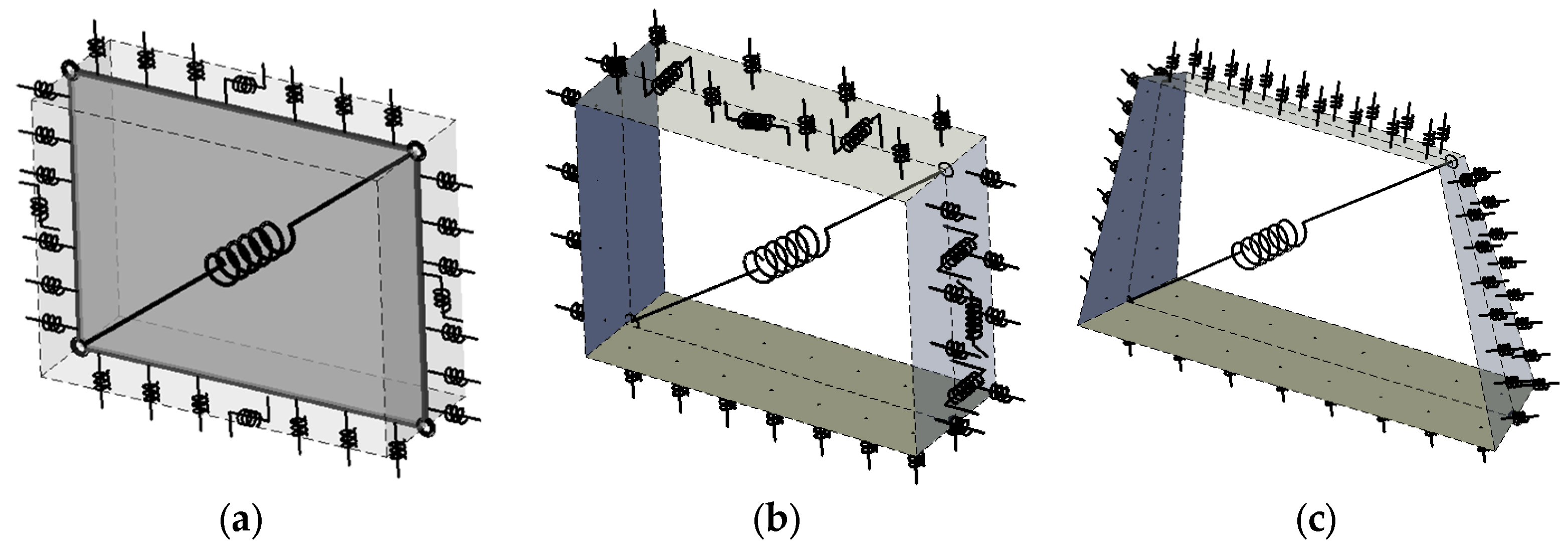
The arch is subjected to the self-weight and to a horizontal mass proportional load distribution (p0), as represented in Figure 3, increased until the complete collapse of the structure. The results of the push-over analyses are presented both in terms of capacity curves, and collapse mechanisms. The capacity curves report the maximum lateral displacement of the arch vs. the base shear coefficient (base shear normalized by the own weight).
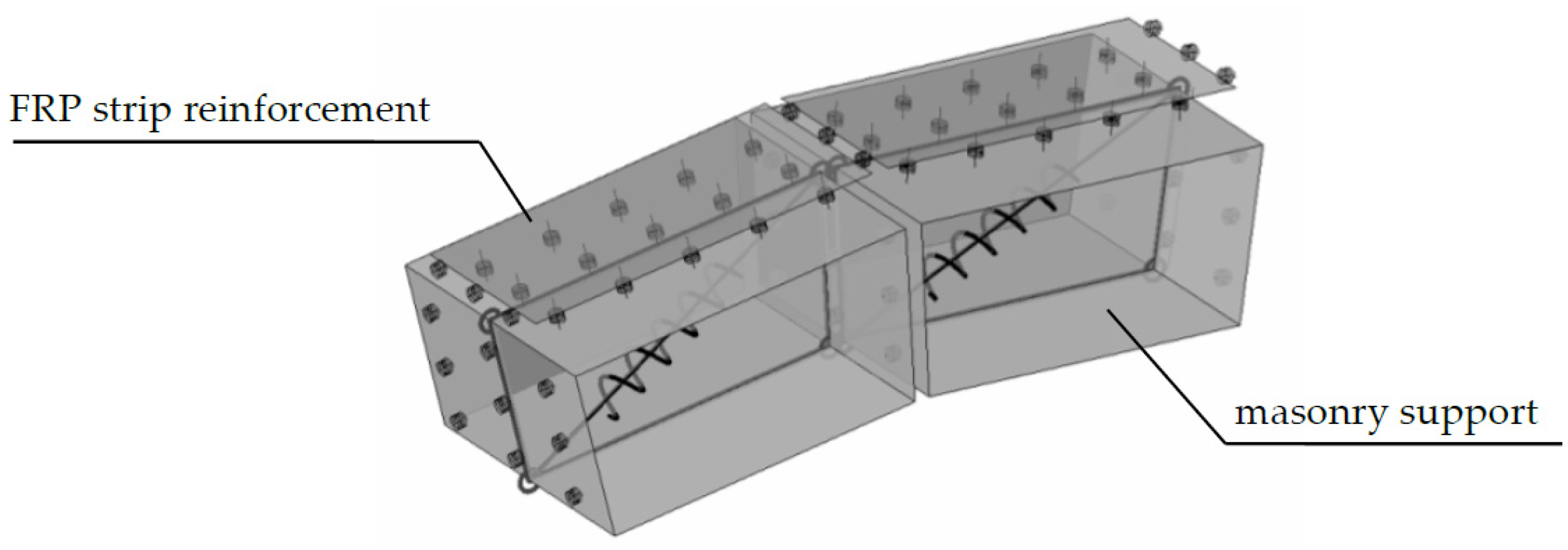
In order to calibrate the numerical model, an initial comparison was performed with the results of the experimental campaign reported in [26]. In the mentioned paper two identical arches were subjected to a vertical concentrated load according to the experimental layout reported in Figure 4. The mechanical parameters of the masonry have been estimated by means of experimental tests [26], and are here reported in Table 1. E and G represent the normal and the tangential deformation moduli of masonry, σt and σc the tensile and compressive strengths, Gt and Gc the corresponding values of fracture energy, c the cohesion, μ the friction factor, and w the specific self-weight of masonry.
The results of the macro-element model are reported in terms of capacity curve (applied force vs. vertical displacement at the loaded section) with the black line, and are compared with the experimental capacity curves or the two specimens (grey lines). In terms of collapse mechanism, the location and the opening sequence of the plastic hinges are in agreement with the experimental evidence as well.
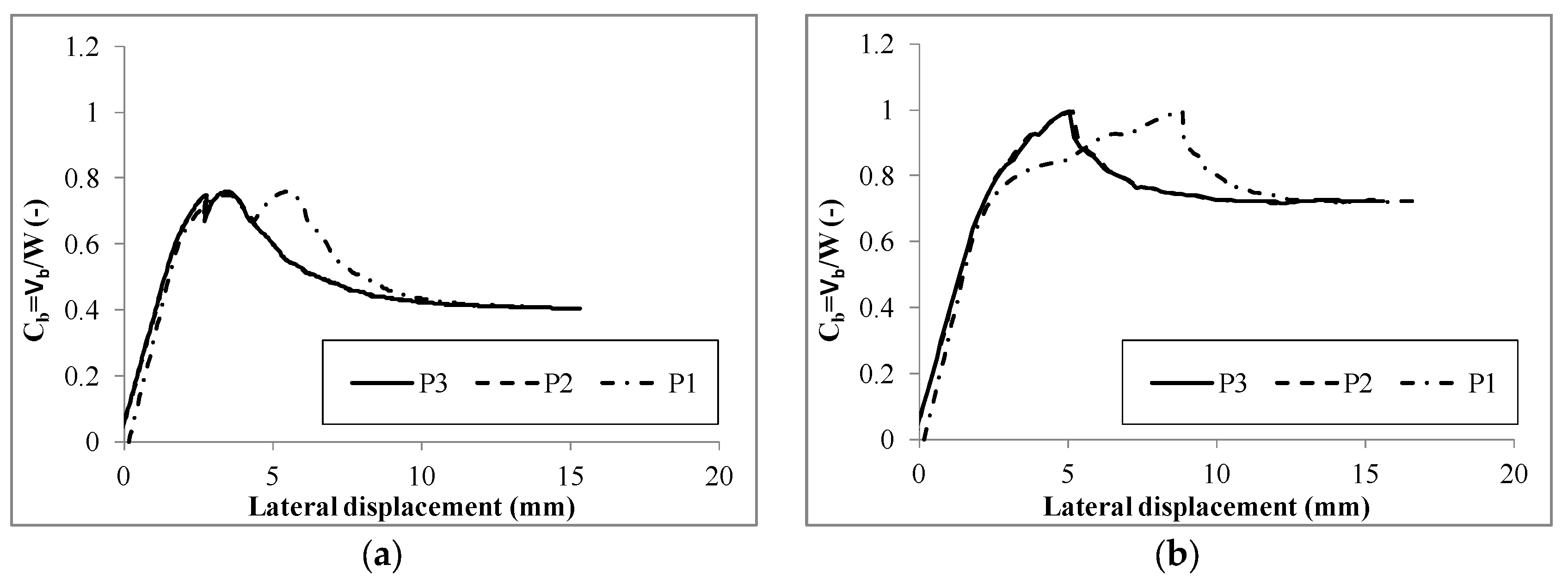
Once the proposed model has been validated considering the masonry arch, as described in Figure 3, and subjected to a concentrated vertical load as reported in Figure 4, the load scenario corresponding to a uniform horizontal load is considered in the following (Figure 3). In particular, Figure 5 reports the capacity curves relative to the different geometries in terms of global base shear Vb (Figure 5a) and in terms of base shear coefficient Cb = Vb/W (Figure 5b), being W the total weight of the arch. It can be observed that, as the radius of the arch increases, the global resistance of the arch increases as well (Figure 5a). On the contrary, in terms of the base shear coefficient, as the radius increases, the peak strength reduces, and all the models tend to the same residual strength (Figure 5b).
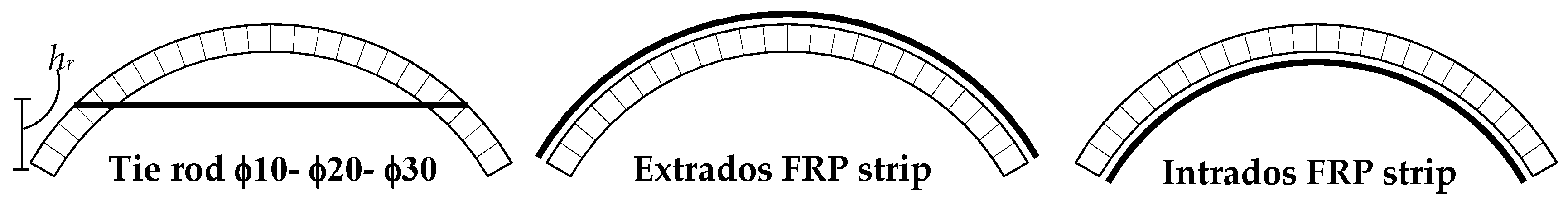
With regard to the assessment of the effectiveness of the structural retrofitting of the arch, three different typologies of reinforcing are considered. The first one consists of the introduction of a tie rod, whose diameter varies proportionally to the radius of the arch, from ф10 mm in the case of R = 866 mm, to ф30 mm in the case of R = 2500 mm, with Young’s modulus E = 200 GPa, and an ultimate tensile strength equal to fy = 200 Mpa. The diameters of the tie-rods are empirically chosen among commercial diameters, keeping constant the ratio between the radius of the arch and the diameter of the tie-rod. In the considered models the tie-rods’ heights hr with respect to the base of the arch is about R/4 (Figure 6). The yielding stress of the steel has been chosen among widely adopted steel typologies, and large enough to keep the tie-rods in the elastic field. The other two strategies consist of the introduction of FRP strips, at the intrados and at the extrados surfaces respectively (Figure 6). The reinforcement is constituted by strips arranged over the entire width and length of the arch made of glass fiber composite material (GFRP) and organic matrix. The adopted mechanical properties have been set according to [27], and reported in Table 2, in which Ef and ft are the tensile module and the ultimate tensile strength of the reinforcement, and tf is the equivalent thickness. The bond-slip behaviour is described by the initial shear stiffness of the matrix ks, the ultimate debonding stress tf, the fracture energy Gs, and the friction factor μs.
Figure 7 shows the failure mechanisms of the reinforced arches, respectively with R = 2500 mm and R = 866 mm. The collapse mechanism observed for the model reinforced with the tie rod is very similar to the failure mechanism of the unreinforced arch, which is not here reported for the sake of conciseness. The latter aspect seems to demonstrate that the presence of the tie rod does not increase the strength of the arch, at least in seismic conditions and neglecting the interaction with the underlying walls. On the contrary, the failure mechanisms of the arches reinforced by means of FRP strips are characterized by a wide spread of the damage. It is worth to note that, due to the transfer of tangential stress between the FRP strip and the arch, the presence of FRP strips delays or prevents the opening of plastic hinges on the surface to which the strips are applied. For all of the investigated cases, the failure mechanism is concentrated in the masonry and in the FRP strips due to the tensile rupture; whereas, no shear no delamination of the reinforcement is encountered. In both cases of strips applied to the intrados and to the extrados, the failure is associated to the activation of an intermediate plastic hinge. The latter is located on the extrados surface of the arch in the case of the intrados reinforcing (point A1 in Figure 7a and point A2 in Figure 7b) or at the intrados surface, closer the support of the arch, in the case of the extrados reinforcing (point B1 in Figure 7a and point B2 in Figure 7b). It is worth to note that, although the arches reported in Figure 7 are not scaled according to the relevant radius, they refer to different size of the arch, as better specified in the caption.
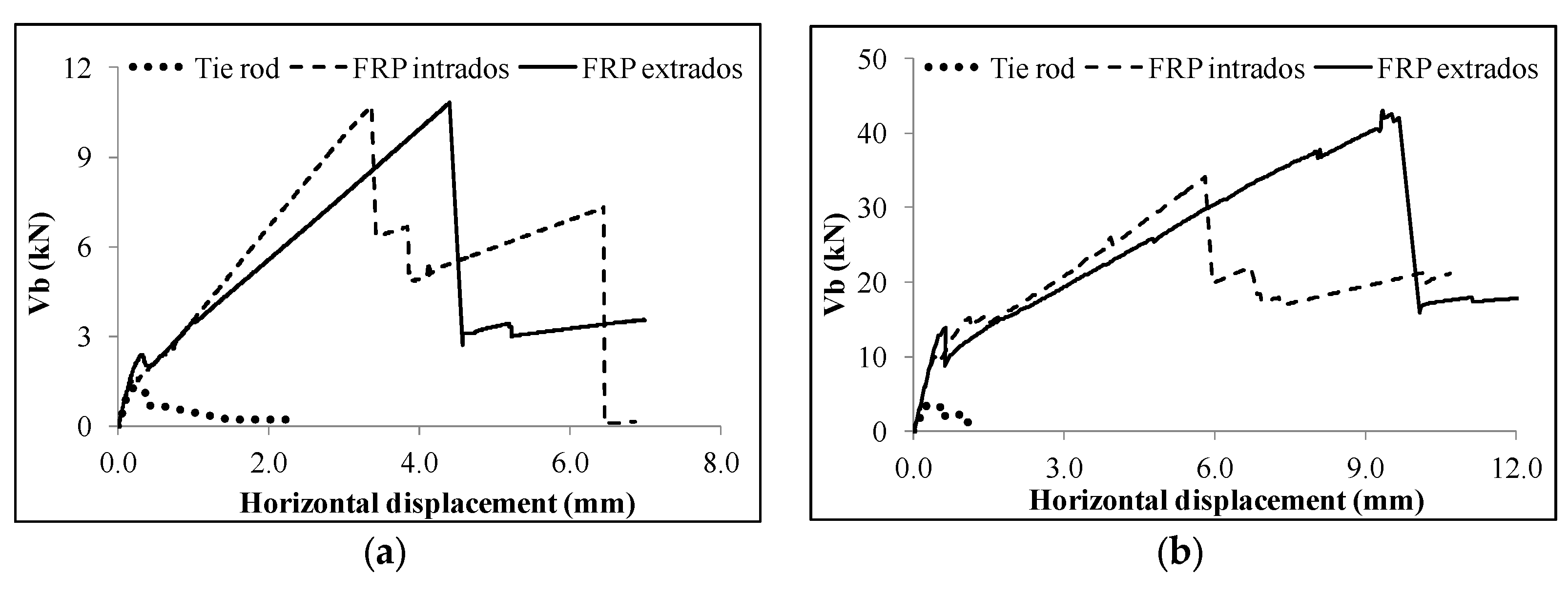
Figure 8 shows the comparison of the considered reinforcing techniques in terms of capacity curves for two of the three radiuses investigated: the smallest (866 mm) and the largest (2500 mm). The capacity curves and the failure mechanisms of the models reinforced with tie rods are very close to the findings relative to the unreinforced model, whereas the capacity curves of the arches reinforced by means of the FRP strips show significant increments, both in terms of strength and ductility. For those models, after the achievement of the peak load a sudden drop in the global strength is encountered; such a drop is associated to the opening of a cylindrical hinge in the arch, associated to the FRP strip tensile rupture. Then, for larger displacements, the FRP strips-masonry interface tends to mobilize the tangential force, progressively transferring stresses to the fibres. The latter aspect implies a higher residual force of the strengthened models with respect to the unstrengthened model. The influence of the arrangement of the FRP reinforcement (at the extrados or at the intrados) on the global resistance is negligible in the case of R = 866 mm (Figure 8a), while this effect is important in the case of R = 2500 mm (Figure 8b).
The presence of the FRP composite strips produces an increment of the ultimate bending moment of the cross section of the arch. In order to highlight the contribution of the reinforcement on the structural response, the eccentricity of the normal action (e = M/N), normalized with respect to the height H of the section, along the curvilinear abscissa (s) of the arch, normalized with respect to the arch length Φ, is reported in Figure 9. In particular, the arches with R = 866 mm are considered, both in the configurations with FRP at the extrados (Figure 9a) and at the intrados (Figure 9b). The tensile axial force (N) is considered positive, and the bending moment (M) is considered positive if it stretches the FRP reinforcement fibres. The zero of the abscissa is set at the left abutment, while the unit value corresponds to the right abutment of the arch. The reported eccentricities are associated to the peak-load conditions, which are characterised by the opening of three hinges in both of the considered cases. In the model reinforced at the extrados (Figure 9a), two hinges are located at the intrados (at the normalized abscissa 0.29 and at the right end of the arch) and one hinge corresponding to the tensile rupture of the textile, is opened at the extrados at the left end of the arch. In the model reinforced at the intrados, two hinges are located at the extrados (left end of the arch and at the normalized abscissa 0.67), and one hinge at the intrados, located at the right end of the arch.
It is important to notice that the distribution of the plastic hinges in correspondence of the peak-load does not correspond to the locations at collapse (Figure 7), since the rupture of the textile, corresponding to the third plastic hinge, implies an internal force redistribution which induces the opening of hinges in masonry at different locations.
In Figure 9 the theoretical limit values of the eccentricity, as evaluated through the limit analysis approach [26], are reported. The masonry is considered as a no-tension material and linear-elastic in compression, whereas the FRP strips are not capable of transferring compressive force and elastic-brittle in tension. The limit conditions, reported with dashed lines, are associated to the rupture in traction of the FRP strip (curved lines), and to the tensile action on the masonry (straight lines at the dimensionless eccentricity 0.5). The grey areas in the graphs represent the field of the admissible eccentricities. It is worth noting that the left parts of the arches are in tension while the right parts are in compression. This is due to the particular load scenario here considered (i.e., horizontal force distribution proportional to the self-mass of the arch). In proximity of the abscissa associated to the change of sign of the normal force, the eccentricities tend to diverge (see Figure 9a,b). In order to clarify the equilibrium of the reinforced arch cross section, simple schemes are reported in Figure 9c,d, for the case of extrados and intrados reinforcing, respectively. In each figure the two possible scenarios are reported: tensile (N > 0) and compressive axial force (N < 0). The grey areas (whose height is equal to x) and the white ones (whose height is equal to H − x) represent the areas in compression and tension, respectively. The internal forces are represented by the tensile action of the FRP strip (Fs) and the global compression on the masonry (Rc). The ultimate equilibrium of the section is imposed by considering the ultimate value of Fs and evaluating the corresponding value of x under the hypothesis of linear elastic behaviour of the masonry (confirmed by the numerical simulations). Once the internal forces are computed, the ultimate moment (Mu) and the ultimate eccentricity e lim ( N ) = M u / N can be easily inferred.
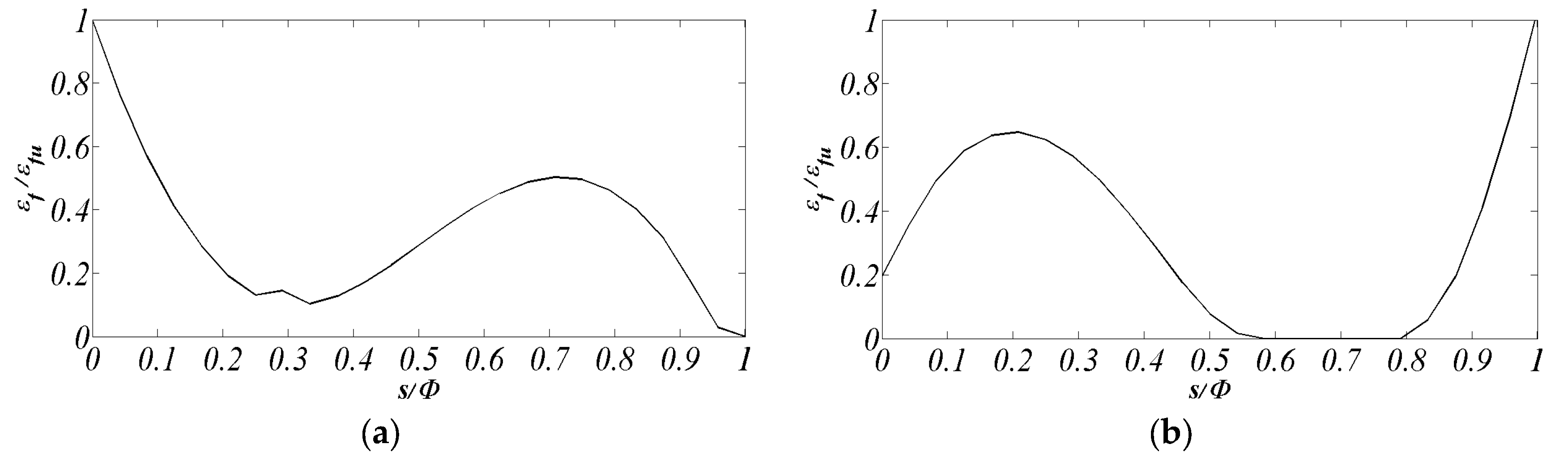
Figure 10 shows the working rates of the reinforcement at the peak load of the arches with R = 866 mm reinforced at the extrados (Figure 10a) and at the intrados (Figure 10b). The working rates are expressed in terms of εf/εfu, being εf and εfu the current and the ultimate tensile strains of the textile, respectively. These rates are useful to identify the achievement of the tensile rupture of the reinforcement, which is here identified at the left end of the arch for the model reinforced at the extrados, and at the right end of the arch for the model reinforced at the intrados. These ruptures produce the sudden drops of the global resistance, as observed in the global capacity curves.
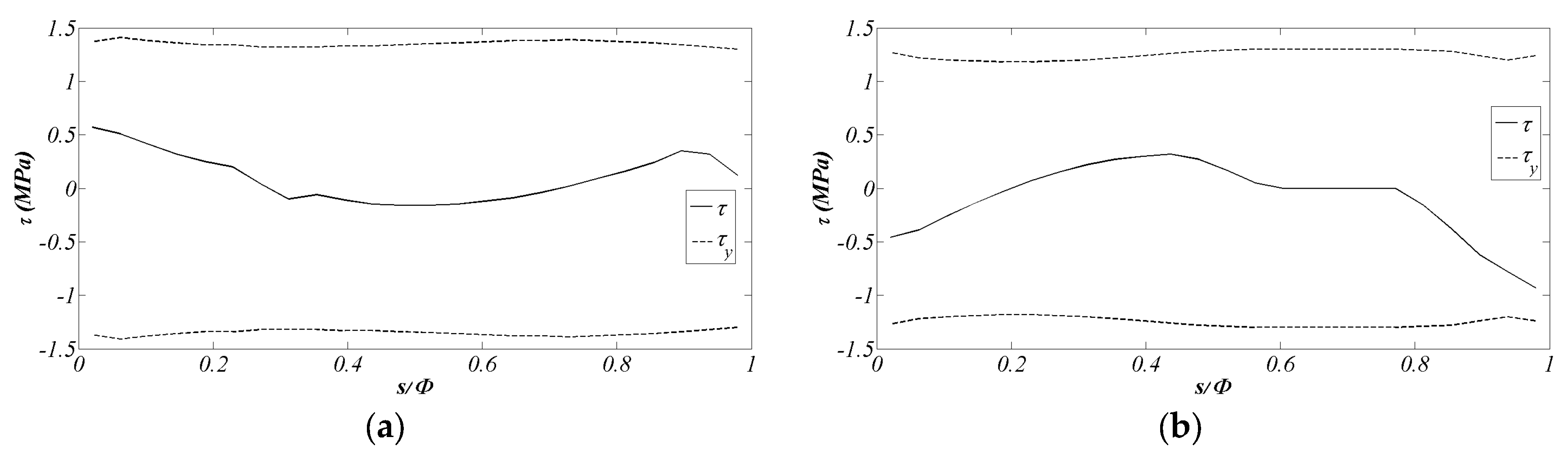
Aiming at highlighting the shear bond behaviour of the FRP reinforcement, in Figure 11 shows the tangential stress τ at the interface between masonry and FRP reinforcement in correspondence of the peak load (continuous lines), as well as the yielding tangential stress τy(N) at the same step (dashed lines), depending on the current compression force on the interface (N). The figures refer to the arches with R = 866 mm reinforced at the extrados (Figure 11a) and at the intrados (Figure 11b). In both cases, the tangential stress is lower than the corresponding yielding value confirming that the debonding mechanism does not occur. The latter results are apparently in contrast with other experimental and numerical results available in the literature, obtained considering similar FRP reinforced prototypes subjected to a vertical eccentric force [27]. The fact that no delamination phenomenon occurs for the treated cases might be due, in part, to the geometry and in part to the horizontal mass-proportional load distribution considered.
A comparison among all the reinforced and unreinforced models, in terms of ultimate load capacity (Vb,max) and increment of resistance (ΔVb), is reported in Table 3. The benefits in terms of strength resistance are higher in the models with the lowest radius (R = 866 mm) and the beneficial effects decrease as the radius increases. Furthermore, the comparison of the effects of the extrados and intrados arrangements of the FRP strips demonstrates that the scale effect observed in Figure 8 is confirmed for all of the cases investigated: in addition, for small radius models the application of FRP strips to the intrados and to the extrados provides similar effects (see the first column of Table 3), while in the case of large radius models the benefit associated to the extrados FRP reinforcement is significantly higher if compared to the intrados reinforcing.
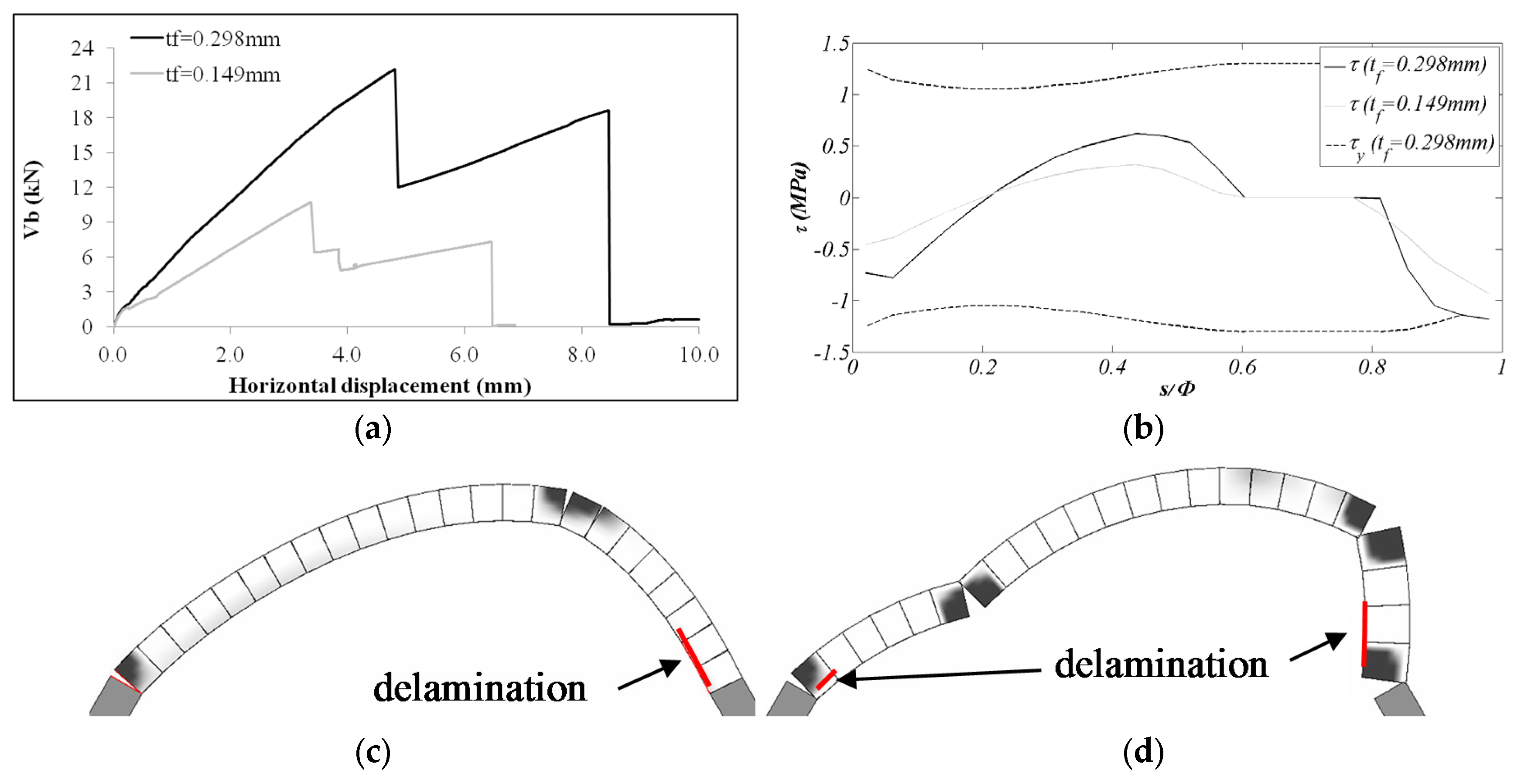
Finally, in order to investigate the influence of the fibre content on the lateral strength of the structure, a further parametric investigation on the arch with R = 866 mm reinforced at the intrados is performed. In particular, a model considering a double equivalent thickness of reinforcement (tf = 0.298 mm) is investigated.
In Figure 12, the corresponding capacity curve is reported (Figure 12a) together with the trend of the tangential stress at the interface between masonry and FRP reinforcement (Figure 12b), and the damage pattern in correspondence of the peak load and the collapse of the arch (Figure 12c,d). In Figure 12a,b, the pushover curve and the corresponding tangential stresses of the previously investigated model (tf = 0.149 mm) are reported for comparison. An increment of strength and ductility is associated to the model with tf = 0.298 mm if compared to the standard thickness model. However in this case the ultimate lateral capacity is limited by the activation of the delamination as demonstrated by tangential stress distribution, which overlaps the yielding stress close to the right end of the arch (Figure 12b). At the peak load, the opening of the cylindrical hinges at the intrados is significantly delayed by the presence of FRP reinforcement (Figure 12c), causing a significant delamination in the post-peak branch (Figure 12d).

4.2. Hemisperical Dome

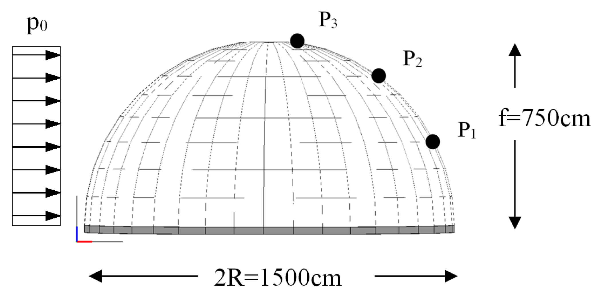
A further example relative to a double curvature vault is considered in this section. In particular, a masonry hemi-spherical dome, already studied in the elastic field in [28], with a thickness t = 20 cm, and whose geometric layout is reported in Figure 13 is here studied with reference to the nonlinear field. The masonry dome is initially subjected to its own self-weight, and subsequently, a horizontal force distribution proportional to the masses (p0) is applied until collapse in order to investigate a typical load scenario in seismic conditions.
The displacements of three different nodes has been monitored according to the layout showed in Figure 13. The adopted mechanical properties for the numerical simulations are reported in 
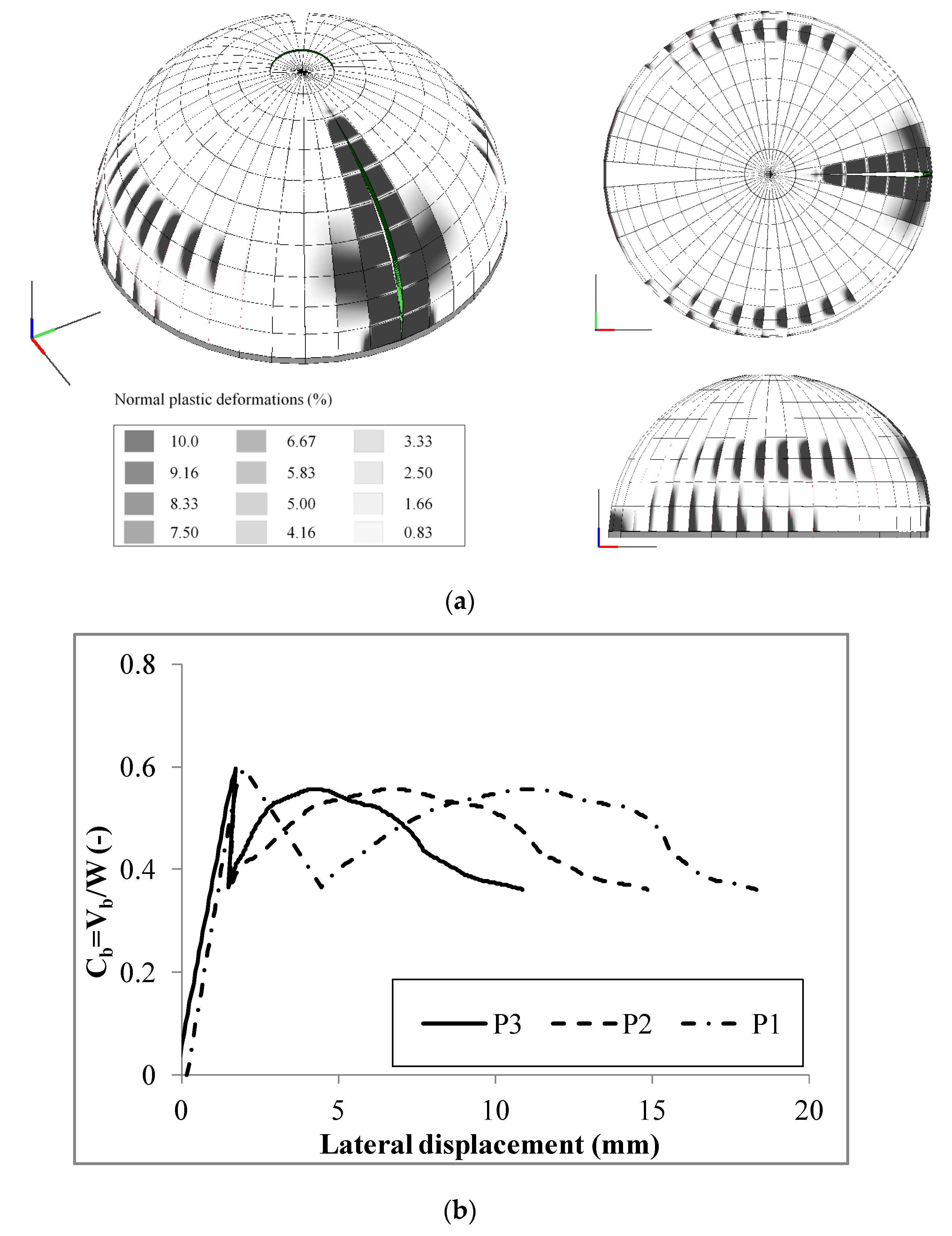
Table 4. The results are reported in Figure 14 in terms of collapse mechanisms, damage patterns (Figure 14a), and capacity curves with respect to the three monitored nodes (Figure 14b).
The collapse mechanism is characterized by a large damaged area along the meridians in the positive direction of the load and two smaller damaged areas at about a latitude of 30° at the two symmetric upper and lower sides orthogonal to the direction of the load distribution. In terms of capacity curves, the structure is characterized by a significant peak load (Cb = 0.6) and by a significant residual resistance as well. It is worth to note that the horizontal displacements of the monitored points decrease as the height of the control point increases.
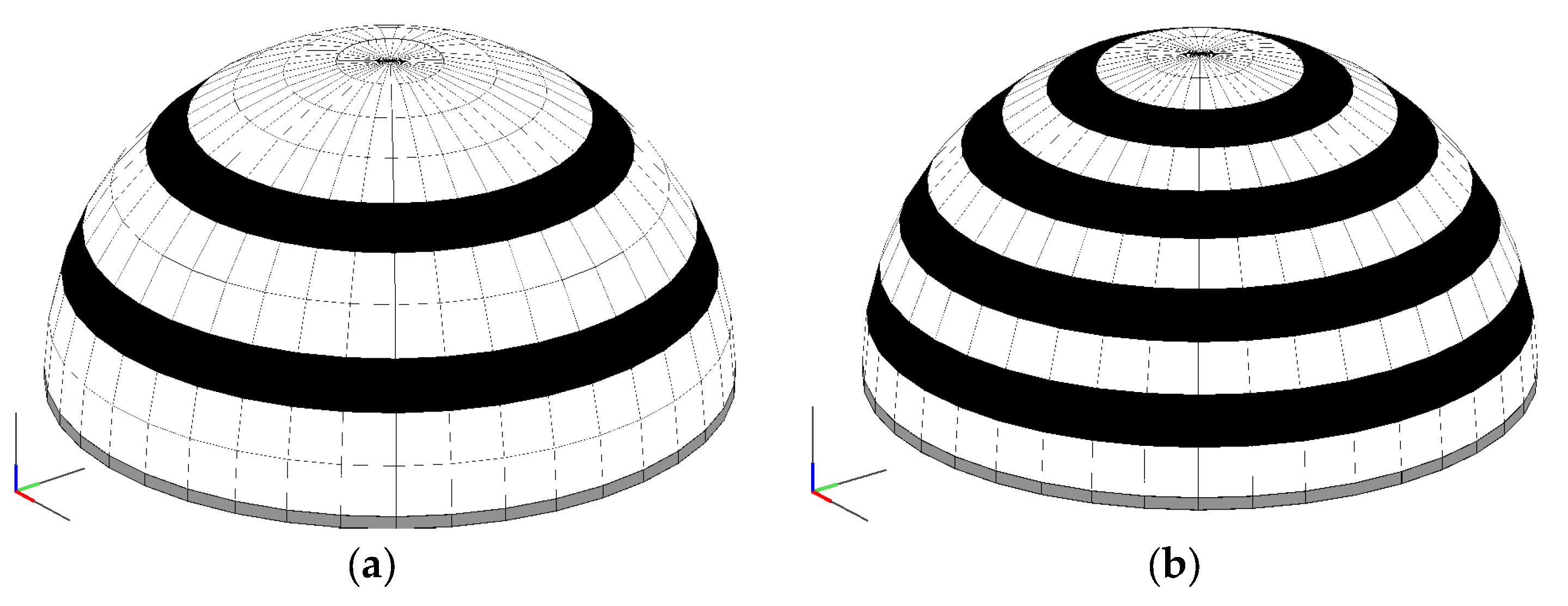
Regarding the structural retrofitting strategies, the application of FRP strips has been adopted. The strips (which have a width equal to 120 cm) have been arranged along the parallels to prevent the occurrence of damage along the meridians. Two different levels of retrofitting have been considered: a soft one with two strips centred at the latitudes of 22.5° and 49.5° (Figure 15a), and a strong retrofitting with four strips centred, respectively, at the latitudes of 13.5°, 31.5°, 49.5°, and 67.5° (Figure 15b). The same mechanical properties of the reinforcement considered for the circular arches, are adopted (see Table 2).
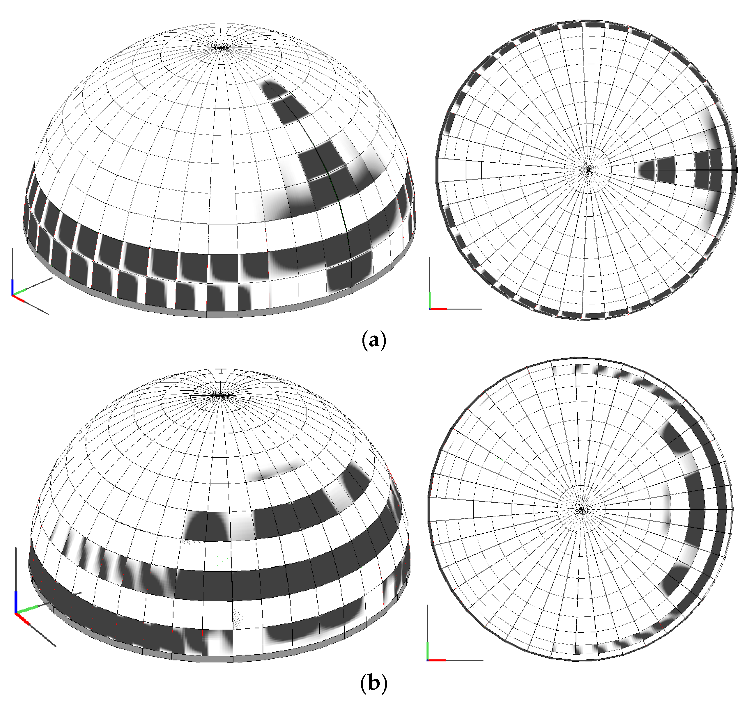
Again, the results are reported in terms of collapse mechanisms (Figure 16), and pushover curves, considering the same three monitored displacements of the unreinforced configuration (Figure 17). As expected, increasing resistances are obtained with both the softly and strongly reinforced models with respect to the unreinforced configuration. In both cases the three monitored nodes show closer displacements to each other. Nevertheless, only in the post peak branches the lowest of the monitored nodes have larger displacements than the other two. The latter aspect is due to the confinement effect of the FRP strips, as demonstrated also by the damage distribution at the collapse, which show how plastic strains develop only along the unreinforced parts of the meridians. The failure mechanism of both reinforced models are characterized by a spread damage at the base section of the dome, below the first FRP strip. In the model reinforced by two strips (soft reinforcing), the damage propagates along the entire height of the dome involving a limited radial portion (Figure 16a). A different failure mode is observed for the model reinforced by four FRP strips (strong reinforcing): in this case the damage propagates above the lowest strip involving a large portion of the dome, the damage doesn’t propagate at the top of the dome (Figure 16b).
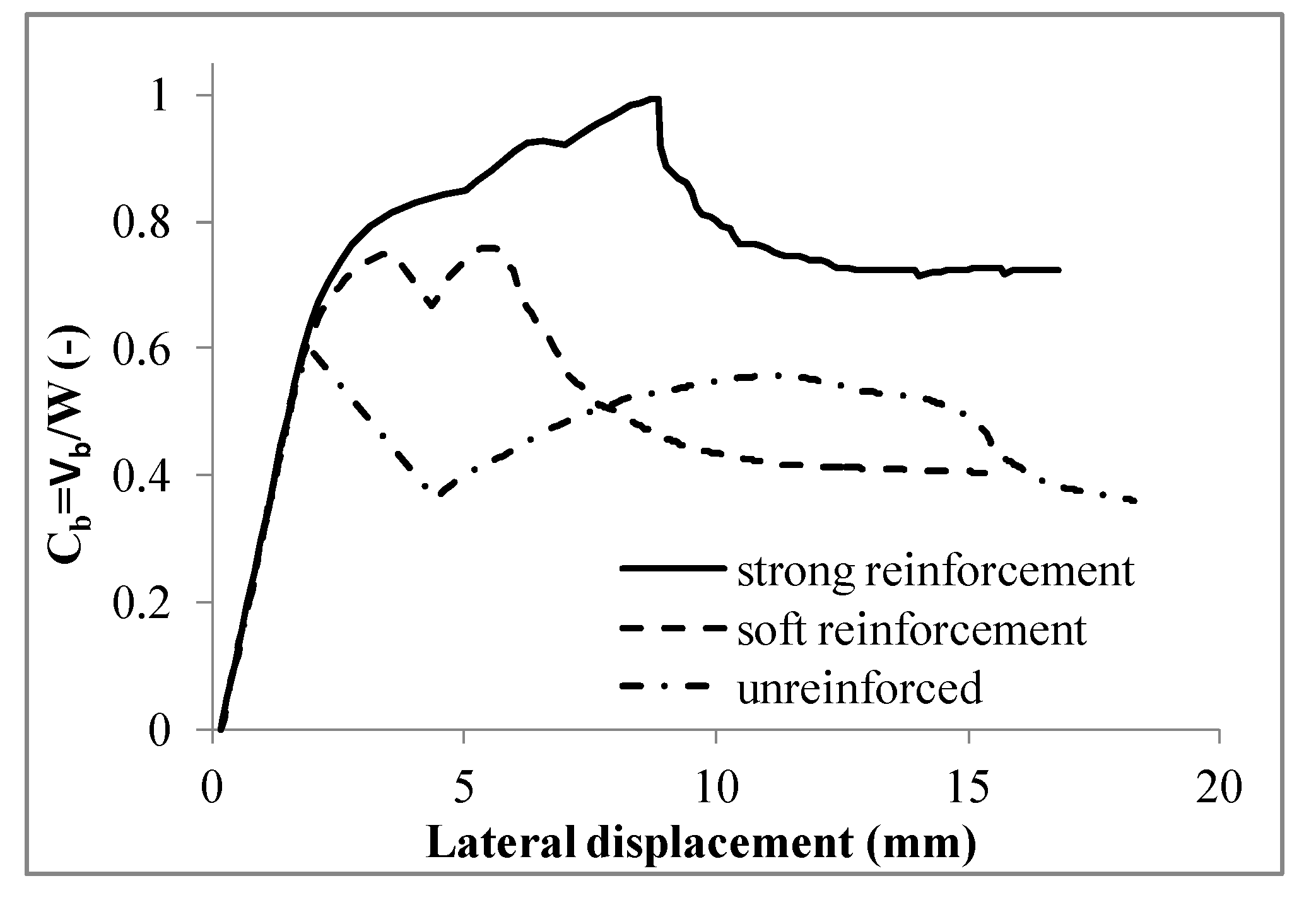
The comparison in terms of pushover curves between the unreinforced configuration and the two retrofitted domes, as reported in Figure 18, considering as monitored displacement P1, shows the effectiveness of the FRP retrofitting technique, which leads to a significant improvement in terms of resistance without implying any global stiffness alteration, thus guaranteeing that no significant change of the seismic demand for the structure occurs. On the other hand, the presence of FRP strips, not only increases the peak load of the arch, but significantly delays the loss of resistance in the post-peak branch (from around 2.5 mm for the unreinforced dome, to around 10 mm for the case of the strongly retrofitted dome), thus guaranteeing to the dome a larger ductility as well. In Table 5 the ultimate lateral resistance (Cb,max) and the percentages of strength increment (ΔCb) are reported, highlighting the enhancement associated to the FRP reinforcement application. The softly retrofitted model presents a residual lateral strength close to that relative to the unreinforced model, whereas the strongly retrofitted model presents a higher value of residual resistance due to a larger spreading of the damage at the ultimate condition, as shown in Figure 18.
It is worth to point out that the numerical investigation reported in this section considers only the load scenario corresponding to a horizontal force distribution proportional to the masses, representative of seismic condition. Nevertheless, structures can be subjected to very different load scenarios (e.g., static conditions, concentrated loads). Further investigations to assess the effectiveness of FRP strengthening technique, under different seismic loads distributions (e.g., proportional to the eigenmodes) or static loads should be investigated in further studies.

5. Conclusions

A comprehensive discrete element strategy to simulate the nonlinear behaviour of existing masonry structures is employed here. The adopted model, based on a simple but effective mechanical scheme, was initially conceived for the nonlinear simulation of the in-plane behaviour of the masonry panels, and then upgraded to account for the out-of-plane behaviour and for the presence of curved elements (such as arches and vaults). More recently, the same modelling strategy has been extended with a new discrete element to model FRP strips, able to interact with a masonry support. In this paper, the numerical results obtained with this strategy are shown, aiming at demonstrating its capability to grasp the pre- and post-retrofitting capacities in seismic conditions. The approach has been first validated with a comparison with the results obtained in the nonlinear static context on a unreinforced masonry arch; then, the benefits provided by traditional and innovative retrofitting techniques (namely insertion of tie rods and application of FRP strips) are assessed and discussed. Significant vault typologies with a scheme of both single and double curvature masonry structures are considered. The results relative to the arches are validated by the comparison with analytical results, as obtained through the limit analysis approach in order to demonstrate the effectiveness of the proposed approach to grasp the ultimate behaviour of the reinforced masonry cross sections (activation of the plastic hinges), and the changing of the global collapse of the structure. The proposed approach, being based on a model in which masonry and FRP strips are modelled with separate elements interacting with each other by means of discrete interfaces, is able to clearly identify the actual failure mode of the structure. The seismic load scenario, which, in spite of its high risk is not very debated in the academic literature, is here investigated, and the effectiveness of widely adopted FRP reinforcement arrangements are assessed and discussed. In spite of the relevance of the achieved results, in the future further investigations will be needed to assess different retrofitting techniques, also considering other load scenarios and structural typologies. In addition, with regard to the application of FRP reinforcements, different disposals of the strips have to be investigated with the aim of providing useful guidelines for the optimal retrofitting design.

Author Contributions

B.P. and F.C. conceived the investigation strategy; B.P., C.C. and F.C. developed and calibrated the numerical models, analysed the results and wrote the paper; I.C., S.C and P.B.L. supervised the research, approved the outcome of the numerical investigations and revised the paper.

Conflicts of Interest

The authors declare no conflict of interest.

References

  1. Huerta, S. Structural Design in the Work of Gaudi. J. Archit. Sci. Rev. 2006, 49, 324–339. [Google Scholar] [CrossRef]
  2. Foti, D.; De Tommasi, D. An Innovative Modular System for the Building of Timber Cylindrical Roofs. Int. J. Mech. 2013, 7, 226–233. [Google Scholar]
  3. Fabbrocino, F.; Farina, I.; Berardi, V.P.; Ferreira, A.J.M.; Fraternali, F. On the thrust surface of unreinforced and FRP-/FRCM-reinforced masonry domes. Compos. Part B Eng. 2013, 83, 297–305. [Google Scholar] [CrossRef]
  4. Carpentieri, G.; Modano, M.; Fabbrocino, F.; Feo, L.; Fraternali, F. On the minimal mass reinforcement of masonry structures with arbitrary shapes. Meccanica 2017, 1, 1561–1576. [Google Scholar] [CrossRef]
  5. Fraternali, F.; Carpentieri, G.; Modano, M.; Fabbrocino, F.; Skelton, R.E. A tensegrity approach to the optimal reinforcement of masonry domes and vaults through fiber-reinforced composite materials. Compos. Struct. 2015, 134, 247–254. [Google Scholar] [CrossRef]
  6. Foti, D. On the numerical and experimental strengthening assessment of tufa masonry with FRP. Mech. Adv. Mater. Struct. 2013, 20, 163–175. [Google Scholar] [CrossRef]
  7. Capozucca, R. Experimental FRP/SRP-historic masonry delamination. Compos. Struct. 2010, 92, 891–903. [Google Scholar] [CrossRef]
  8. Valluzzi, M.R.; Oliveira, D.V.; Caratelli, A.; Castori, G.; Corradi, M.; De Felice, G.; Garbin, E.; Garcia, D.; Garmendia, L.; Grande, E.; et al. Round Robin Test for composite-to-brick shear bond characterization. Mater. Struct. 2012, 45, 1761–1791. [Google Scholar] [CrossRef] [Green Version]
  9. Napoli, A.; de Felice, G.; De Santis, S.; Realfonzo, R. Bond behaviour of Steel Reinforced Polymer strengthening systems. Compos. Struct. 2016, 152, 499–515. [Google Scholar] [CrossRef]
  10. Bertolesi, E.; Fabbrocino, F.; Formisano, A.; Grande, E.; Milani, G. FRP-Strengthening of Curved Masonry Structures: Local Bond Behavior and Global Response. In Proceedings of the Mechanics of Masonry Structures Strengthened with Composite Materials (MURICO5), Bologna, Italy, 28–30 June 2017. [Google Scholar]
  11. Malena, M.; de Felice, G. Debonding of composites on a curved masonry substrate: Experimental results and analytical formulation. Compos. Struct. 2014, 112, 194–206. [Google Scholar] [CrossRef]
  12. Caliò, I.; Marletta, M.; Pantò, B. A new discrete element model for the evaluation of the seismic behaviour of unreinforced masonry buildings. Eng. Struct. 2012, 40, 327–338. [Google Scholar] [CrossRef]
  13. Marques, R.; Lourenço, P.B. Possibilities and comparison of structural component models for the seismic assessment of modern unreinforced masonry buildings. Comput. Struct. 2011, 89, 2079–2091. [Google Scholar] [CrossRef] [Green Version]
  14. Caliò, I.; Pantò, B. A macro-element modelling approach of Infilled Frame Structures. Comput. Struct. 2014, 143, 91–107. [Google Scholar] [CrossRef]
  15. Caliò, I.; Cannizzaro, F.; D’Amore, E.; Marletta, M.; Pantò, B. A new discrete-element approach for the assessment of the seismic resistance of composite reinforced concrete-masonry buildings. Proc. AIP Am. Inst. Phys. 2008, 1020, 832–839. [Google Scholar]
  16. Caddemi, S.; Caliò, I.; Cannizzaro, F.; Pantò, B. A new computational strategy for the seismic assessment of infilled frame structures. In Proceedings of the 2013 Civil-Comp Proceedings, Sardinia, Italy, 3–6 September 2013. [Google Scholar]
  17. Pantò, B.; Cannizzaro, F.; Caliò, I.; Lourenço, P.B. Numerical and experimental validation of a 3D macro-model for the in-plane and out-of-plane behaviour of unreinforced masonry walls. Int. J. Archit. Herit. 2017, 1–19. [Google Scholar] [CrossRef]
  18. Pantò, B. La Modellazione Sismica Degli Edifici in Muratura. Un Approccio Innovativo Basato su un Macro-Elemento spaziale. Ph.D. Thesis, University of Catania, Catania, Italy, April 2007. [Google Scholar]
  19. Caliò, I.; Cannizzaro, F.; Marletta, M. A discrete element for modeling masonry vaults. Adv. Mater. Res. 2010, 133–134, 447–452. [Google Scholar] [CrossRef]
  20. Caddemi, S.; Caliò, I.; Cannizzaro, F.; Pantò, B. The Seismic Assessment of Historical Masonry Structures. In Proceedings of the 12th International Conference on Computational Structures Technology, Naples, Italy, 2–5 September 2014. [Google Scholar]
  21. Cannizzaro, F. Un Nuovo Approccio di Modellazione Della Risposta Sismica di Edifici Storici. Ph.D. Thesis, University of Catania, Catania, Italy, April 2011. [Google Scholar]
  22. Caddemi, S.; Caliò, I.; Cannizzaro, F.; Lourenço, P.B.; Pantò, B. FRP-reinforced masonry structures: Numerical modelling by means of a new discrete element approach. In Proceedings of the 6th International Conference on Computational Methods in Structural Dynamics and Earthquake Engineering, Rhodes Island, Greece, 15–17 June 2017. [Google Scholar]
  23. Cannizzaro, F.; Lourenço, P.B. Simulation of Shake Table Tests on Out-of-Plane Masonry Buildings. Part (VI): Discrete Element Approach. Int. J. Archit. Herit. 2017, 11, 125–142. [Google Scholar] [CrossRef]
  24. Pantò, B.; Cannizzaro, F.; Caddemi, S.; Caliò, I. 3D macro-element modelling approach for seismic assessment of historical masonry churches. Adv. Eng. Softw. 2016, 97, 40–59. [Google Scholar] [CrossRef]
  25. Chácara, C.; Lourenço, P.B.; Pantò, B.; Cannizzaro, F.; Caliò, I. Parametric numerical studies on the dynamic response of unreinforced masonry structures. In 2016 Structural Analysis of Historical Constructions: Anamnesis, Diagnosis, Therapy, Controls: Proceedings of the 10th International Conference on Structural Analysis of Historical Constructions (SAHC, Leuven, Belgium, 13–15 September 2016); CRC Press: Boca Raton, FL, USA, 2016; pp. 239–245. [Google Scholar]
  26. Alecci, V.; Focacci, F.; Rovero, L.; Stipo, G.; De Stefano, M. Extrados strengthening of brick masonry arches with PBO–FRCM composites: Experimental and analytical investigations. Compos. Struct. 2016, 149, 184–196. [Google Scholar] [CrossRef]
  27. Basilio, I. Strenghtening of Arched Masonry Structures with Composite Materials. Ph.D. Thesis, University of Minho, Guimares, Portugal, July 2007. [Google Scholar]
  28. Caddemi, S.; Caliò, I.; Cannizzaro, F.; Occhipinti, G.; Pantò, B. A parsimonious discrete model for the seismic assessment of monumental structures. In 2015 Civil-Comp Proceedings; Civil-Comp Press: Stirlingshire, UK, 2015. [Google Scholar]
Figure 1. Layout of the macro-element adopted for masonry at its three stages: (a) plane element, (b) spatial regular element and (c) three-dimensional element for curved structures.
Buildings 07 00079 g001
Figure 2. Schematic layout of the interaction between masonry elements and discrete fabric-reinforced polymeric (FRP) reinforcement elements.
Buildings 07 00079 g002
Figure 3. Geometry of the arch with the indication of the seismic load condition (p0).
Buildings 07 00079 g003
Figure 4. Validation of the numerical model.
Buildings 07 00079 g004
Figure 5. Capacity curves of the unreinforced arches, expressed in terms of (a) global base shear, and (b) base shear coefficient.
Buildings 07 00079 g005
Figure 6. Different reinforcing interventions considered for the arch.
Buildings 07 00079 g006
Figure 7. Failure mechanisms of the reinforced (a) R = 2500 mm and (b) R = 866 mm arches.
Buildings 07 00079 g007
Figure 8. Capacity curves of the reinforced arch: (a) R = 866 mm; (b) R = 2500 mm.
Buildings 07 00079 g008
Figure 9. Contribution of the FRP reinforcement at the peak load: normalized abscissa versus eccentricity of the acting force of the models with R = 866 reinforced at the (a) extrados and (b) intrados. Cross section internal equilibrium for extrados (c) and intrados (d) reinforcing.
Buildings 07 00079 g009
Figure 10. Contribution of the FRP reinforcement at the peak load: normalized abscissa versus working rates of the reinforcement for the models reinforced at the (a) extrados and (b) intrados.
Buildings 07 00079 g010
Figure 11. Tangential stress at the interface between masonry and FRP reinforcement in correspondence of the peak load for the models reinforced at the (a) extrados; and (b) intrados.
Buildings 07 00079 g011
Figure 12. Arch with R = 866 mm reinforced at the intrados with a double thickness of the textile (tf = 0.298 mm): (a) capacity curve; (b) tangential stress at the interface between masonry and FRP reinforcement in correspondence of the peak load, damage pattern at (c) the peak load; and (d) collapse.
Buildings 07 00079 g012
Figure 13. Geometry of the dome and control points.
Buildings 07 00079 g013
Figure 14. Response of the unreinforced dome in terms of (a) failure mechanism; and (b) capacity curves.
Buildings 07 00079 g014
Figure 15. Typologies of reinforcing: (a) soft and (b) strong retrofitting.
Buildings 07 00079 g015
Figure 16. Failure mechanisms of the reinforced models: dome with (a) soft; and (b) strong reinforcement.
Buildings 07 00079 g016
Figure 17. Capacity curves of the reinforced models: (a) soft and (b) strong retrofitting.
Buildings 07 00079 g017
Figure 18. Comparison of the capacity curves of the unreinforced and reinforced models.
Buildings 07 00079 g018
Table 1. Mechanical property of the masonry.
E (Mpa)G (Mpa)σt (Mpa)σc (Mpa)Gt (N/mm)Gc (N/mm)c (Mpa)μ (-)W (kN/m3)
270010800.308.530.010.300.260.618
Table 2. Tensile and bond-slip parameters of the FRP reinforcement.
Tensile Bond-Slip
Ef (GPa)ft (MPa) tf (mm)ks (N/mm3)τf (MPa)Gs (N/mm)μs (-)
45014730.149201.32.50.75
Table 3. Ultimate strength of the arches and increment of the ultimate load with respect to the unreinforced configuration.
ModelR = 866 mmR = 1500 mmR = 2500 mm
Vb,max (kN)ΔVb (%)Vb,max (kN)ΔVb (%)Vb,max (kN)ΔVb (%)
Unreinforced 1.23-3.43-9.26-
Tie rod1.2303.4309.260
Intrados FRP 10.8378019.1445834.10268
Extrados FRP 10.7277221.9353943.00364
Table 4. Mechanical characteristics of the masonry.
E (Mpa)G (Mpa)σt (Mpa)σc (Mpa)Gt (N/mm)Gc (N/mm)c (Mpa)μ (-)w (kN/m3)
12004800.152.500.100.50.150.725
Table 5. Ultimate strength of the domes.
ModelCb,max (-)ΔCb (%)
Unreinforced 0.60-
Softly retrofitted0.7525
Strongly retrofitted1.0067

