1. Introduction
Buildings are evolving from containers that provide a safe and comfortable environment for the tenant into active participants of a smart infrastructure, where they pursue multi-objective goals in controlling their internal processes. Such a flexible operation of building resources requires seamless integration of the building systems into a building management system (BMS). Integrated building management has, therefore, become significant. Demand side management, optimization of costs and energy efficiency, remote maintenance of building portfolios, migration of intelligence from in-house hardware to external data centers and the role of smart buildings in a smart city are all upcoming developments in building automation. It is, therefore, necessary to prepare building automation systems by taking a look at the organization of deployment and operation of the BMS and improving these processes to make buildings ready for the next step.
The task of introducing a structured description and process into the interdisciplinary field of building commissioning is challenging in different regards: first, building construction and especially commissioning of the building automation system is subject to volatile goals that may change at various stages throughout the process. It is, therefore, necessary to design a deployment process that has the necessary flexibility. Second, the process, as we know it today, strongly depends on experts that operate on their experience and execute processes that are neither well documented nor externalized or accessible in a structured way. Today it is a well-known fact that buildings require time to be operated optimally. Interviews with experts in the field of commissioning and optimizing building automation revealed that it may take one, or even two, full years before a building can reach its energy efficiency optimum, a fact which, unfortunately, is widely accepted. Reasons are found to be changes of systems during the building phase, time constraints during commissioning, and the lack of communication between the building appliance domain and the measuring and control experts. Introducing a structured commissioning process together with tools that support automation of tasks, as well as building simulation has the potential to speed up the optimization process, thus, saving significant amounts of energy and personnel costs. Introducing software support and, especially, simulation support as means to improve the quality of deployment is a step that has significant impact as it paves the way to automate quality control on large parts of the deployment. Once the data acquired in the different steps is accessible (e.g., status on design brief acquisition, commissioning data, heating, ventilation and air conditioning (HVAC) system information, comparison of thermal simulation opposed to real monitoring data, etc.) it is a strong support for a human integrator to make checks of completeness, consistency, and correctness, and implement proper change management (e.g., to ensure that changes in an HVAC component are also reflected in the control strategy).
In this paper we describe the integration of models and data from domains that still do not cooperate well. By addressing the problem of controls deployment in building systems, and by identifying, understanding and describing the underlying processes, the problem becomes accessible and enables the aforementioned tool support and task automation. The definition of work flows and the supporting workbench framework lays the foundation of structured, automated, and optimized deployment. We especially focus on a part of the workbench implementation, the Model Manager, which is the core module for handling e.g., thermal simulations needed for the evaluation of the thermal performance of a building.
As stated earlier, building automation has the objectives to ensure thermal and visual comfort, indoor air quality and, more recently, efficient operation with respect to energy and costs. To achieve this, it is important to have continuous energy management complemented by the implementation of energy and cost saving strategies. This can be provided by a Simulation-assisted Building Control (SaBC) service. SaBC is a dynamic system whose main purpose is to support simulation assisted indoor environmental control operations in buildings. In an SaBC, future control steps are projected from available model and building data through simulation. Then, computed values of pertinent performance indicators, are predicted, compared, and ranked [
1].
The advantage of such a control system is that it can harmonize efficiency goals with comfort goals, while having the parameters and operating points of individual system components (e.g., heat exchangers, ventilation, etc.) in its focus which leads to an unprecedented level of operational efficiency. Due to the amount of information gathered by the model, it can also support other building tasks, such as those concerned with building logistics and management.
This paper describes the architecture of an SaBC, and shows how it can be deployed. The deployment is particularly challenging when compared to conventional automation systems, because there is a huge fragmentation among system manufacturers with regard to system architectures, data models, and data communication protocols. The proposed architecture has been derived from a process that is the result of previous projects [
1] and additional field tests [
2]. The architecture’s outstanding property is that the deployment of Simulation-assisted Building Control system can be achieved completely technology independent to a degree where the different modules can be fully automated, semi-automated or even done under manual control. In the preceding projects, the architectural design has been reiterated and improved, yielding the architecture available today. It is certainly not the only solution, but it has proven its feasibility. We give detailed descriptions of the Model Manager module, since it is vital for the operation of an SaBC and allows some deep insights on the intended operation and mode of use.
The rest of the paper is organized as follows:
Section 2 gives an overview of the related work in the field,
Section 3 describes the simulation assisted architecture,
Section 4 goes into detail on the Model Manager Module, while
Section 5 presents the results that have been achieved. The paper closes with a conclusion in
Section 6.
2. Related Work
The cross-domain nature of both systems and integration requires to define building automation tasks and communication infrastructure as described in [
3]: the authors discuss the most common open systems, namely BACnet, LonWorks, and KNX and they analyze application models, requirements and services for defining building automation tasks.
An extensive discussion on real-time simulation-based building control with the focus on building performance can be found in [
4] and is further extended by validated implementations in lighting and shading domains [
1]. A framework that allows a real-time comparison of actual and simulation-based building performance has been developed in [
5]. The framework has a modular architecture composed of an Energy Management and Control System (EMCS) and a Real-time Simulation Environment. The EMCS offers a BACnet gateway to interface existing sensors and control devices. The Real-time Simulation Environment utilizes the Building Controls Virtual Test Bed (BCVTB) [
6] as a link between the simulation tool, the control systems and EnergyPlus [
7] as a simulation tool. Brunner [
8] presented a Building Model Service where the current building state is reflected in an object tree that is continuously updated by sensor data. A building model based on a Shared Object Model (SOM) was used in [
9]. SOM is a fairly straight-forward object hierarchy and served well as a simple building model representation. Brunner argues in [
10] that this simplification is an advantage over, e.g., Industry Foundation Classes due to the resource saving creation of a simplified model. A building monitoring, control, and interface system architecture and functionality have been introduced [
11]. Model-based approaches in building management have been applied in different projects: the OptiControl project [
12] has used model-based control to optimize HVAC and sublind control in prototype installations. Use cases for model-assisted building HVAC system control parameters fine-tuning are examined in [
13], and the Pebble project [
14] examines the improvement of control decisions in order to achieve positive energy buildings. An approach for reducing the efforts for thermal modeling of buildings by decreasing the accuracy and the complexity of the building model is described in [
15]. Similar research on model simplification to reduce the modeling effort and easing the development of dependent technologies is shown in [
16,
17]. A dynamic adaptation of the model resolution depending on the state of planning is discussed in [
18], while [
16] presents a methodology for automated building model generation, based on the Energy Performance Certificate (EPC)—an implementation of Directive 2010/31/EU, 2010 [
19]. Advanced automation and control for buildings and their components promotes energy consumption reduction [
20] and grid-friendly buildings have the potential to meliorate grid management. In this context demand response can be supported by electro-thermal processes in buildings [
21]. Building energy simulators require a certain level of technical expertise to be used [
22]. Consequently, trained professionals are necessary to perform building energy analysis, which result in additional costs [
22]. Even though that trained auditors, in general, produce more customized and accurate building energy analysis, the additional costs involved may deter many building owners from adopting building energy simulation for the assessment of the building performance [
22].
A new dynamic simulation model for the building energy performance analysis, called DETECt 2.1, has been recently proposed in [
23], focusing on reliable thermal loads and energy demands simulation as well as accurate dynamic temperature profiles, allowing modeling and simulation in a modular and scalable way. DETECt 2.1 has been implemented in MATLAB and validated by a standard code-to-code comparison (BESTEST procedure).
3. Simulation Assisted Building Controls
In this chapter we describe the properties of an SaBC together with the system architecture in which it is embedded. The following chapter will detail the Model Manager, which is a central part of the SaBC.
3.1. System Architecture
A building automation system has two relevant levels of management and control functionality that play a role in the architecture described in this paper. On process level the controllers—mainly linear PID controllers—are responsible to follow set-point trajectories, or attain a given set-points. On management level there are state-machine-like logics that set the schedules for machine operation and provides the set-points for the underlying controllers. Note that we intentionally leave out higher layers like Enterprise Resource Planning (ERP) and we also do not separate process level into sensor/actuator, field and control level, since the two levels of management and control provide the necessary logical granularity relevant for the system architecture.
Building automation operates in a mixed hardware and software environment. Hardware is distributed in the building, on the building envelope, the roof or nearby the building. Software (e.g., controller logic and automation logic) can be bundled in several substations, in which one substation controls a set of components. It can also be located in a device like a heat pump, where the manufacturer has placed an embedded system responsible for the control of and communication with the heat pump. Such components are integrated into the system on management level by changing set-points and schedules.
Supervisory control and all higher management levels like Enterprise Resource Planning (ERP) are loosely coupled to the building automation system and commonly connected over regular office networks. When supervisory control is not connected to the automation system, the building operator cannot change operation states and has no information on the system state. Still, the automation system remains fully functional and is capable of running autonomously, since all control and automation logic remains in operation. This is also an indicator for the required robustness—building automation systems on process level need to be highly reliable and run unattended, while supervisory control has the common robustness requirements of consumer software that tolerates occasional failures or maintenance intervals.
The SaBC process model interacts with supervisory control, augmenting it with functions and services for modeling and simulation. This has an impact on the controllers, but does not directly influence controllers. Instead it uses the regular interface between supervisory control and controller logic (e.g., by changing set-points and schedules). Furthermore, the SaBC extends the view of classical building automation by allowing controllers and sensors to be human operators, that is, data is gathered by humans and control actions are performed manually.
3.2. Process Model
The deployment of an SaBC service is a complex task, involving different professionals, each of them possibly assuming multiple roles. A role may be concerned with the physical building (for example architects, structural engineers, electrical engineers, mechanical engineers, builders, and field integrators) or the building automation system (for example, control engineers, software engineers, software architects, software developers, test engineers, and deployment engineers). In building systems engineering, there is a role of master integrator [
24]. It is a role that encompasses understanding buildings as a system, perceiving critical needs of all stakeholders, discerning the functional core of the system and being able to communicate it to others. This role is also assumed to have the main responsibility for SaBC deployment. The master integrator is likely to combine several roles related to the building automation system. He leads all tasks of the deployment process, managing the coordination between building designers and building automation system designers, along with the communication and feedback to building owners, facility managers, and building tenants.
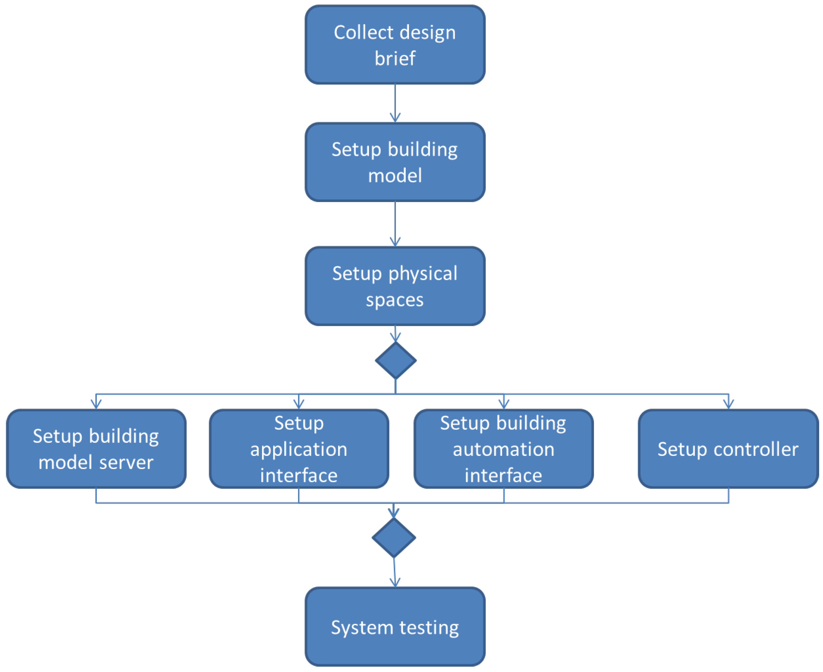
We propose a work-flow model for SaBC deployment. Potential benefits of such a model include improved deployment planning, coordination and collaboration, more efficient deployment and higher quality on an SaBC system. Additionally, it allows a functional and non-functional assessment of the deployment tasks. The SaBC deployment process is divided into several main tasks. These tasks are: collect design brief, setup building model, setup physical spaces, setup building model server, setup application interface, setup building automation interface, setup controller, and system testing (
Figure 1).
Figure 1.
Top level view of the deployment process.
Figure 1.
Top level view of the deployment process.
At first an understanding about the deployment project has to be developed. The master integrator gathers data concerning the building, building systems and SaBC goals in this deployment context. During the building model setup task, data concerning the building systems models are collected. This facilitates the building model generation and maintenance. A BIM may be used to support this task. The setup physical spaces task is done for each space in the building. A space in this context is a continuous area or room. For example physical spaces are rooms in the built environment. Consequently this task is a highly iterative and time consuming. In case of a large building, or when many identical rooms are present, it may be possible to reduce the number of spaces which need to be commissioned by selecting a smaller amount of representative rooms, though the setup physical spaces task remains unaltered. The building model server, the application interface, the building automation interface and the controller may be configured and tested independently of each other. During building model server setup, the building model and simulation module are readied for operation. Again a BIM may be used to store and maintain the building model. The application interface connects client applications to the SaBC system. For example, the Siemens Desigo building management system offers an application interface for building related information visualization. The building automation interface facilitates the collection and processing of data supplied by sensors. For example, Siemens Desigo using BACnet may be selected as building automation interface [
25]. The controller is responsible for control decisions. It may for example be a physical controller, a rule-based software or even a person, such as a facility manager or a building tenant. In special deployment cases, due to security and safety reasons, a building interface or a controller may be inaccessible, still, a partial deployment process may be performed in those cases. The last task involves a series of functional and non-functional tests on the whole system. In this context, performance, scalability, security and recovery tests have been defined as the most relevant tests. Other tests are also important (for example stress tests, load tests, scalability tests,
etc.), but the former are considered as more important from the SaBC deployment process point of view. To maintain simplicity the deployment process is represented as sequential, but in fact it is iterative. Changes in one task may affect the performance of previous tasks. Thus, in some cases the entire deployment process may have to be restarted.
3.3. Data Exchange and Interoperability
An SaBC has two main external interfaces: a simulation interface that connects external simulation programs and a sensor data interface that exchanges data with the building. The simulation interface is used for tools that handle, e.g., thermal simulation of building physics and energy systems. In this work we have used EnergyPlus, but other tools like TRNSYS or MATLAB are just as feasible. The tools are provided with a building model, start conditions and internal states and are then automatically started to simulate the behavior of the building. After a simulation run, the results are fetched and automatically processed for visualization, but may also be used for further input. EnergyPlus has proven to be sufficiently interoperable, as it operates on textual representation of models, thus, being feasible for machine-to-machine communication, enabling the automatic generation of building models. This unfortunately does not allow fully automated data exchange yet. Although it would be possible to receive a 3D model straight out of the planning process, the available tools and workflows show that an architect has different requirements than thermal simulation has. A Building Information Model (BIM) represented as Green Building XML (gbXML) [
26] or Industry Foundation Class (IFC) [
10] is as such a perfect container to transfer all relevant information from the planning process to a simulation based operation of a building. However, it has proven many times that interoperability cannot be achieved only by defining data container formats. (An example from building automation on the “fieldbus war” can be found in [
27]).
The sensor data interface has two levels. On process level, the connection is established by interfacing with one of the standardized bus systems (LonWorks, BACnet or KNX). This allows using open protocol stack implementations and directly requesting data from the networked building components. It is however necessary to have the necessary metadata available, which identifies the function of a datapoint and helps locating it in the system (e.g., return temperature of heat pump).
The second level is supervisory control. If access to the building automation network is prohibited (e.g., due to robustness concerns), data has to be acquired using the vendor specific supervisory control software. Traditionally, supervisory control is not a platform with open access or standardized interfaces. Unless the vendor supplies the necessary specification or even a tool on how to access the operation data, the data acquisition is tedious, e.g., by exporting unstandardized and undocumented plain text files. A little more convenient is the access of a database that stores operation data. If supervisory control stores historic data in a database system, it is often possible to use standard database queries (e.g., one of various SQL dialects) to access the data.
Both levels—process control and supervisory control—are not limited to machine-to-machine communication. In an SaBC the role of entering data can also be taken over by a human, most likely the building operator.
3.4. Automation of Consistency Check and Validation
Each task in the SaBC deployment process can be assessed regarding its potential for automation. A task may be classified as a data processing or data consistency checking task. Regarding the potential for automation, these may be fully automated, semi-automated or manual.
Data processing in the SaBC deployment process involves recording, analyzing, sorting, summarizing, calculating, disseminating, storing or converting building elements, technical elements geometry or sensor data. In the SaBC deployment process, a data processing task may be a simple and short format conversion, but can also involve long-running simulations. Because these tasks can be data intensive, repetitive, and prone to error, it is important to support them computationally.
Data consistency checking in the SaBC deployment process involves determining the validity, accuracy and integrity of building elements, technical elements geometry or sensor data. It refers to the quality exhibited by the data in relation to the actual scenario. One important component of data consistency checking is data visualization. Data visualization involves displaying building parameters in a way that it supports the analytical process. This is accomplished by data already processed and stored in a previous step.
In order to get reliable data from simulation the underlying models as well as the simulation process need to be validated and consistent. For the thermal simulation of the building performance it is good practice to use validated models. This validation can, for example, be done against ASHRAE Test Cases [
28], which define test scenarios and the expected output. When the simulation software meets these requirements (
i.e., the simulation results match the expected outputs) it is considered to be validated; this implies that it can be used to create validated thermal building models.
Thermal system models have to be validated using real-world data that are collected in a test rig setup. Models that show the same behavior as the one that has been measured at the test rig are considered validated.
4. Workbench Implementation: Model Manager Module
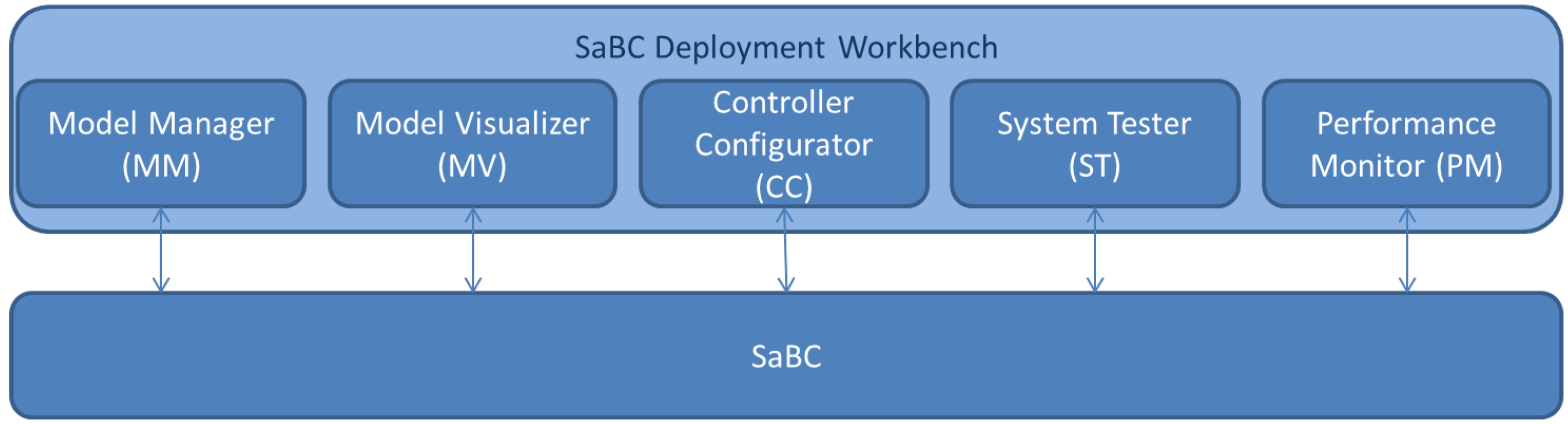
A workbench framework for the SaBC deployment process is proposed. It consists of modules which support data processing and data consistency checking tasks. An overview of the workbench design is shown in
Figure 2.
Figure 2.
Workbench modular view.
Figure 2.
Workbench modular view.
The Model Manager (MM) module handles all building model operations, such as creation, update, duplication, and deletion of building model objects. The Model Visualizer (MV) module is used for building model visualization. The MV module enables a graphical representation of the building model instances, allowing for example the manual validation of building model data. To administer the simulation assisted approach to building control, a Controller Configurator (CC) module is used. Comfort utility functions may be imported, edited and updated. The System Tester (ST) module enables the interaction with devices available in a building environment. For example, by changing device states, it is possible to set the initial device states of an experiment. This is valuable for testing device installations along with performing unit and system tests. The Performance Monitor (PM) module is used to ease performance analysis of an SaBC deployment. This module allows the graphical representation of sensor data, along with simulation results data and other performance indicators. These modules are extensively used during the SaBC deployment process. MM and CC modules support data processing tasks. Whereas ST, MV, and PM modules support data consistency checking tasks. In real world deployments, there are existing systems and infrastructures, which may sometimes be reused for increased cost-effectiveness. But sometimes there may be a need to integrate new tools.
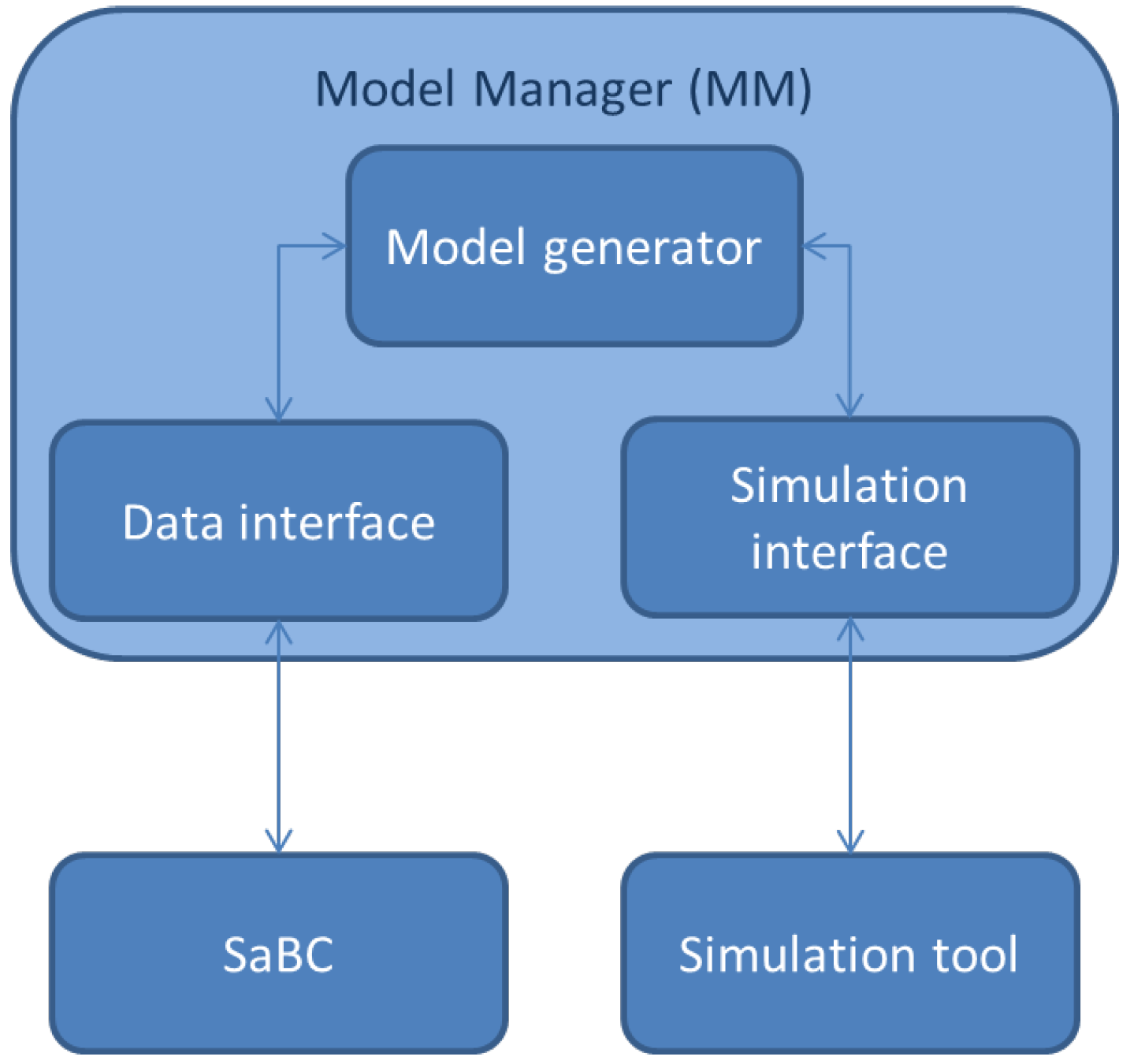
An MM tool, which supports the automatic model creation and calibration process was implemented. A modular system that implements the MM is shown in
Figure 3.
Figure 3.
Model Manager module architecture.
Figure 3.
Model Manager module architecture.
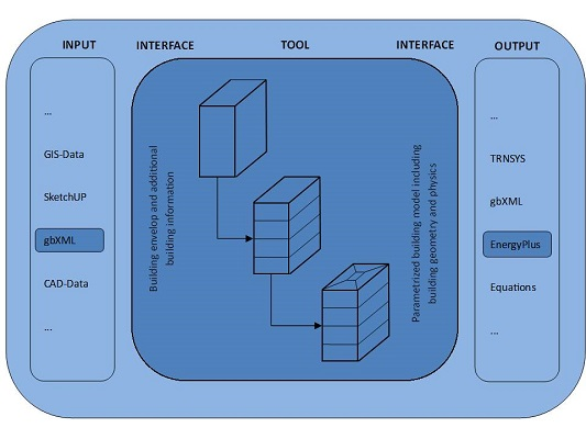
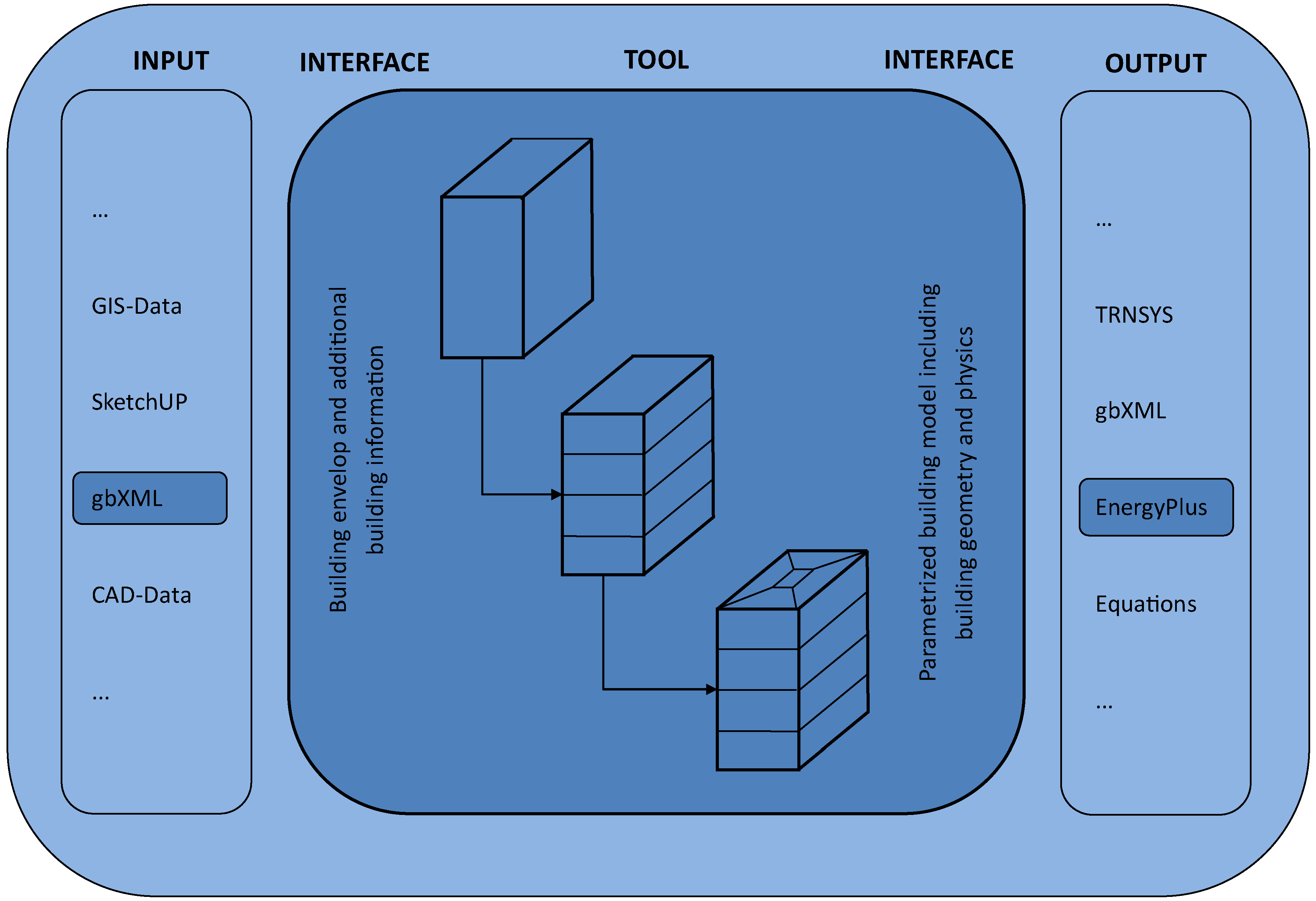
The data interface establishes the communication between the SaBC and the MM. The exchanged data include a 3D building model based on a simplified geometry (building area, height, type, construction year, and percentage of glazing area), the geographic location of the object, physical parameters deducted from the construction type of the building and further internal loads estimated from the usage of the object. The model generator is responsible to automatically generate thermal models based on the building model data. The simulation interface communicates the generated model to the simulation service. Physical parameters such as U-values from walls and windows, wall type, fenestration, location, infiltration rate, ventilation and internal gains may be obtained from the Energy Performance Certificate (EPC). These data are fed into an automated tool, which creates a complete 3D model representing an approximation of the real building geometry and physics, a so-called simplified building model. This enables to perform a thermal building simulation for the measurement period and an appropriate time horizon, using EnergyPlus. To simplify the modeling process, only indoor temperatures set-points for the HVAC system are considered.
5. Evaluation and Results
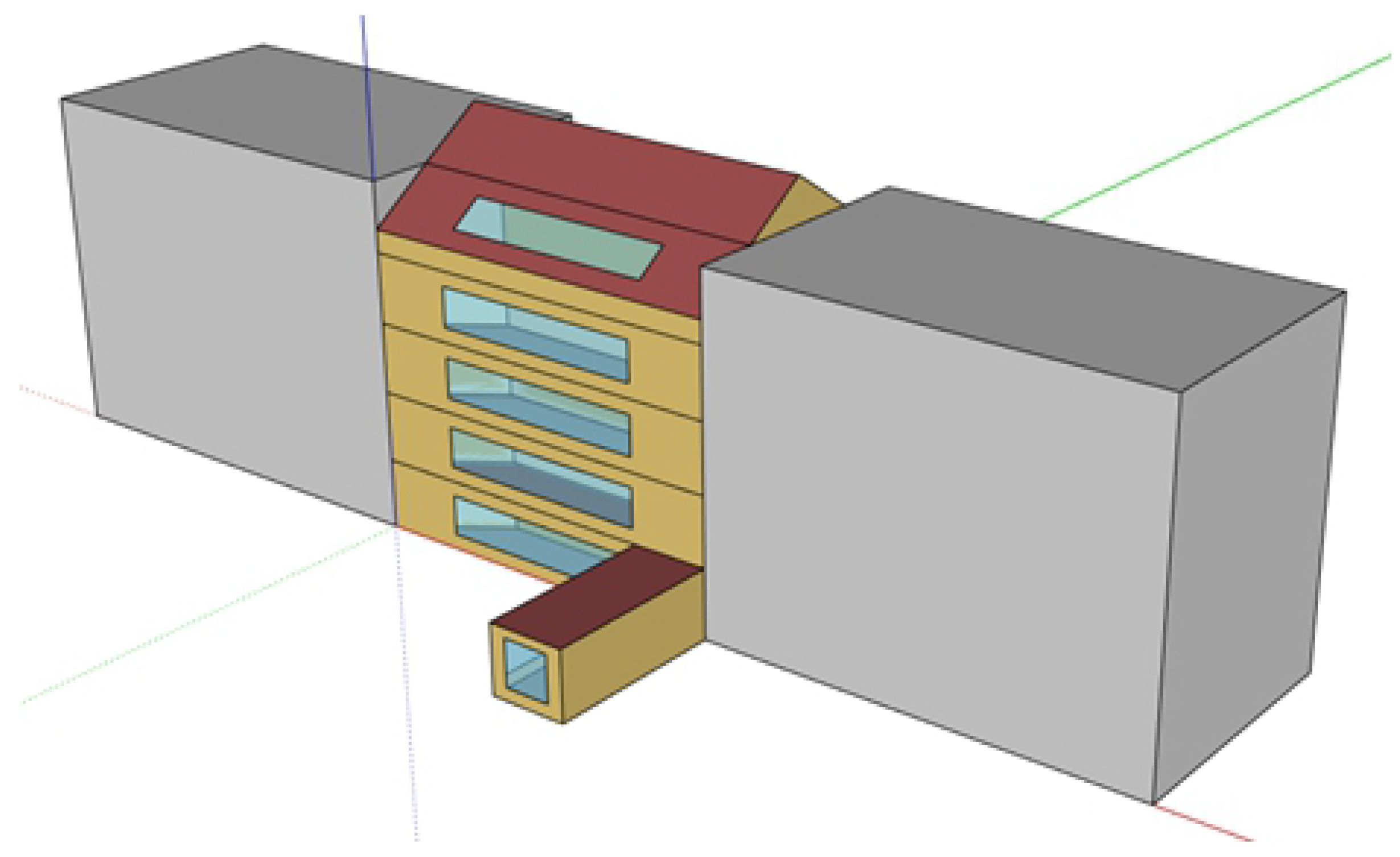
An office building located in Vienna, Austria was selected to validate SaBC deployment and the model manager tool implementation from the workbench framework. The testbed (
Figure 4) is an office building, built in 2006, located in Vienna’s 17th district featuring a gross building area of 1079 m
2 and a gross floor area of 277 m
2. The testbed hosts office units along a production unit. The testbed obtains its thermal energy from district heating and electrical energy from the grid.
Figure 4.
Testbed building model.
Figure 4.
Testbed building model.
An embedded Loytec LINX-120 Automation Server CEA-709 has been installed on-site to measure energy data of the building (total electrical consumption, heating, A/C, air flow) [
29]. It is capable of integrating metering equipment of different technologies, from attaching direct I/O modules (such as pulse counters) to collecting meter data from fieldbus systems such as M-Bus and Modbus. The automation server is also a multi-protocol device that can integrate into existing fieldbus networks that are predominantly used in modern BAS such as LonMark systems (CEA-709), BACnet, or KNX [
30]. For refurbishment sites, sensor equipment for temperature, occupancy and more can be brought into the automation server via the ZigBee wireless protocol [
31].
SaBC is used to predict electrical energy consumption of office appliances and ceiling lights. Users get live feedback regarding energy use via wall-mounted displays. The facility manager gets a periodic report concerning current and forecast electrical consumption. This aims to improve energy consumption awareness, reducing electrical energy consumption by quantifying the predicted consumption. Occupants should become aware of the current consumption and motivated to turn off unnecessary appliances thereby reducing consumption.
A proof-of-concept (PoC) implementation of the MM has been developed.
Figure 5 shows the general overview of this tool for the automated building model creation. As input file a description of the building geometry in Green Building XML (gbXML) format was chosen. In addition to the building information, a simplified building model can be generated. This building model is fed into EnergyPlus for performing thermal simulation. The output is an estimate, based on a thermal simulation, of the energy consumption for heating and cooling. Along these lines, other combinations of input and output tools are also possible, for example supplying equations for custom simulation in MATLAB.
Figure 5.
Schematic overview of the developed tool for building model creation.
Figure 5.
Schematic overview of the developed tool for building model creation.
Building data mandatory for quantitative results e.g., set-points for heating and cooling, time schedules for the HVAC system and internal gains, were identified. This information, together with estimates of not essential data, is representing the inputs for the model creation to support the auto-calibration process. Furthermore the generated models support the ISO 50001 process [
32], by forecasting the yearly or monthly energy consumption of a building. The models allow individual thermal zoning floor by floor with respect to different load profiles and geometry. These two features improve the quality of the energy consumption forecast significantly, and allow for taking into account the increased flexibility in building use.
The model was validated by requesting a thermal simulation and comparing the simulation results with the sensed data. Results, for the heating period, suggest that there is high level of agreement between model and sensed data as shown in
Table 1.
Table 1.
Simulation and measured comparison [
17].
Table 1.
Simulation and measured comparison [17].
| Building System | Simulated (kWh) | Measured (kWh) | Delta (%) |
|---|
| Electrical | 12,917.04 | 11,005.74 | −17.4 |
| Heating | 6,458.6 | 6,781.83 | +5 |
| Cooling | - | - | - |
The results obtained from the preliminary analysis of the simulated and measured data suggest that there is a high concordance between them. Comparing the two results of the electrical consumption it may be seen that there is a variation of 17.4%. Comparing the heating consumption it can be seen that the variation is about 5%. Cooling consumption could not be measured, since results are from a heating time period. Unit tests were performed for the simulation performance analysis.
Table 2 shows the measured performance.
Table 2.
System performance for modeling, simulation and simulation cycle.
Table 2.
System performance for modeling, simulation and simulation cycle.
| Task | Minimum (Seconds) | Maximum (Seconds) | Max−Min (Seconds) |
|---|
| Model generation | 1.06 | 1.13 | 0.07 |
| Simulation | 200.63 | 210.37 | 9.71 |
| Communication | 87.35 | 90.4 | 3.05 |
| Simulation | 289.04 | 301.91 | 12.87 |
A PC equipped with a dual core 2.50 GHz processor and 4 GB RAM was used as simulation hardware. Model generation step needs about 1 s to be accomplished, while the simulation step needs about 200 s to be accomplished. The simulation cycle in total, including model generation, simulation and communication, needs between 289 and 302 s to be completed. It may be noticed that communication and system latency took between 87.4 and 90.4 s. The biggest time consumer is the simulation step, which is performed in approximately 5 min.
In the testbed scenarios are automatically generated and simulated.
Table 3 shows the recorded effort to deploy SaBC, measured in person hours. When measuring the total effort, it may be noticed that the automatic building model generation performed by the Model Manager module from the workbench framework, allowed semi-automated, portable process.
Table 3.
Deployment effort for the testbed, measured in person hours.
Table 3.
Deployment effort for the testbed, measured in person hours.
| Task | Effort (Person Hour) |
|---|
| Collect design brief | 4 |
| Building model setup | 1.5 |
| Physical spaces setup | 8 |
| Building model server setup | 1.5 |
| Application interface setup | 2 |
| Building automation interface setup | 3 |
| Controller setup | 1.5 |
| System testing | 5 |
| Total | 26.5 |
Building modeling, which is traditionally a resource intensive task, has been by these means improved and fasten, to the point where it is no longer the task with higher costs. The building model has been automatically generated using an approximation of the building geometry and building elements. This results in a smaller, simplified model which is suitable for thermal simulation purposes, but lacks accuracy for other purposes, for example light simulation.
6. Conclusions
We have shown a structured process how simulation assisted building control systems can be designed and deployed, followed by a field test on a building that allowed validating the approach. The field test has shown that a structured process saves time and increases the quality of the installation.
An SaBC system is a viable next step in the development of building automation. It can be applied already in the planning phase to support decisions with simulation data, especially when systems have to be changed (e.g., due to cost reasons). In this case the SaBC simulation support allows to assess e.g., the impact on energy efficiency in operation. SaBC provides the container for control decisions, but use cases as described in [
11] have not been implemented. Instead, a regular interface between supervisory control and controller logic has been implemented to cover different control decision scenarios [
2,
17]. In [
33], it has been discussed that the advanced SaBC feedback is desired; however, due to constraints in contracting, safety and security considerations it was not possible to implement it in a real building under operation. The goal of the deployment process is to reduce the deployment effort rather than saving energy.
In order for an SaBC to work it is only necessary to have a definition of the building geometry and the energy systems (mainly HVAC). Early performance assessment using an SaBC system also reduces the “burn-in” phase of building automation, i.e., the time when a building is not optimally configured, because the control strategies still have to be adapted. Finally, an SaBC can also be used to support certification, especially when certificates not only for planning, but also for efficient operation will have to be concerned.


