An Introduction to the Methodology of Earthquake Resistant Structures of Uniform Response

Abstract
:Notation

| f | magnification factor | H | total building height | T | period of vibration |
| i, j | integer coordinates | I | beam moment of inertia | U | internal energy |
| h | story height | J | column moment of inertia | V | shear force |
 | height from base | K | sub frame stiffness | W | sub frame weight |
| m | number of stories | L | span length | Q | total weight |
| n | number of bays | M | beam moment |  | local displacement |
| s | order of occurrence | N | column moment |  | total displacement |
| C | numerical constant | P | joint load |  | drift ratio |
| E | modulus of elasticity |  | beam plastic moment |  | joint rotation |
| F | external force |  | column plastic moment |
1. Introduction
- • A prescribed drift ratio at any given loading or performance stage.
- • A prescribed carrying capacity corresponding to any drift ratio or performance stage, including maximum allowable lateral displacement at incipient collapse.
- • Predetermined sequences of formations of plastic hinges before collapse.
- • Damage control in terms of the number of plastic hinges at any loading or response stage compared with number of plastic hinges at zero loading, at first yield or at incipient collapse.
- • Reduction of the total weight of the structure to a theoretical minimum.
- • The possibility to further enhance or the performance of the structure using moment control technologies such as brackets, haunches, end flange plates and/or proprietary devices.
1.1. Basic Design Objectives
- 1. The ideal inter-story drift ratio remains constant along the height of the structure, and that lateral displacements remain a linear function of the height during all phases of loading.
- 2. The plastic hinges are prevented from forming within columns, except at base line. Whenever possible, base line plastic hinges should form within the grade beams. Global mechanism is reached if the concept of strong-column weak-beam is considered.
- 3. For minimum weight MFUR, the demand-capacity ratios of all members are as close to unity as possible.
1.2. Basic Design Assumptions
- 1. Axial, shear and panel zone deformations are not coupled with flexural displacements and can be temporarily ignored for the purposes of this study.
- 2. Groups of similar members simultaneously resist similar types of loading or combinations of loading, e.g., flexural, axial, torsional, etc.
- 3. The shape of code specified distribution of earthquake forces remains constant during all loading phases. The shape could be triangular or determined by any rational analysis.
- 4. Initial design is based on the fundamental period of vibration of the un-degraded structure.
- 5. The effects of plastic hinge offsets from column center lines can be ignored.
- 6. The possible benefits of strain hardening and yield over-strength can be ignored.
- 7. Code level gravity loads have little or no effect on the ultimate carrying capacity of moment frames designed for moderate to severe earthquakes. However the columns should be designed in such a way as to resist gravity forces together with effects induced by plastic hinging of the beams.
- 8. The design earthquake loads act monotonically throughout the history of loading of the structure.
- 9. The frames are two dimensional and are constructed out of ductile materials and connection failure is prevented under all loading conditions.
- 10. The columns remain effectively elastic during all phases of loading.
2. Methodology

 .
.  is the maximum roof or
  level lateral displacement at
  response stage. Symbol
  signifies increment at consecutive iteration.
 . However,
  or
or  offer more practical options for design purposes. Rotation
  may be construed as the initial target drift corresponding to initial target displacement
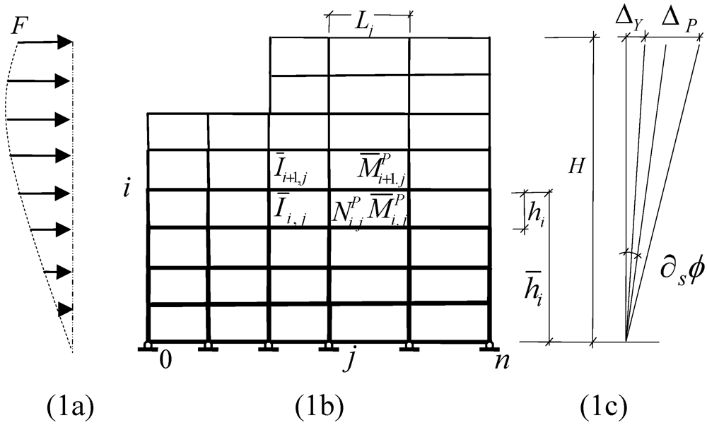
  at first yield. The line diagram of a regular MFUR together with its idealized design displacement profiles, subjected to a generalized distribution of lateral forces, is presented in Figure 1. The design conditions (1a) and (1b) imply equal incremental joint rotations for all members of the frame i.e.,

 at any stage “s” can be expressed as:
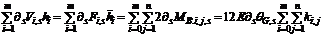
 ,
,  ,
,  and
and  are the story level shear force, relative stiffness, end moments and moment of inertia of beam “i,j” respectively. Equation (2a) directly yields the global rotation of the structure as;
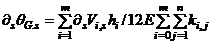
 and
and  are defined as the average and total racking moment acting on
  level beams at response stage respectively.
  , and
, and  correspond to average racking moments of grade and roof level beams respectively.
  is defined as the story raking moment at response stage. Equation (2c) in turn directly yields the floor level rotations as:
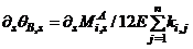
 , then equating the global rotation Equation (2b), and floor level rotation, Equation (2d), gives:
 (3a)
(3a) and expanding the right hand side of Equation (3a), it gives:
 …
…  …
…  (3c)
(3c) ….
….  (3d)
(3d)
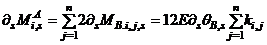
 ,
,  , and
, and  are the relative stiffness, end moments and moment of inertia of column “i,j” respectively. Equation (4b) yields the floor level rotations as:
 is the drift component of the level floor, due to deformations of the columns of the same level. Comparing the two sides of Equations (4a) and (4c) yields the conditions of uniform response or demand-capacity for the columns of the subject frame as:
 ……
……  (4d)
(4d)3. Story Level Elastic-Plastic Displacement Response


 (5b)
(5b)
 to their sequence of formation of plastic hinges or response stage “s”, by means of subscript ”r”, rather than their location “j”. This is achieved by replacing with
  and
and  with
with  and incorporating the symbol
  and
and  in Equation (5c) in order to include the effects of formation or prevention of formation of plastic hinges at the ends of beams “
  ”.i.e.,
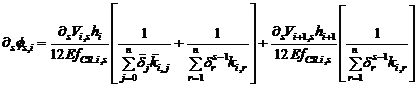
 for
for  and implies structural damage and/or loss of stiffness with respect to beam
 for
for  . In mathematical terms, for
  and for
  Similarly the symbol has
  been introduced to relate column stifnesses
  to effects of formation of plastic hinges in the adjoining beams “i,j” and “i,j-1.
  for
for  and
and  , otherwise
 is the force magnification function.
  and
and  are the total axial load and the critical axial load of level “i” at response stage respectively. In reality, since the drift ratio is constant, it would be sufficient to compute
  for the simplest representative level, i.e., the roof, where,
  . Equation (5d) reduces to:
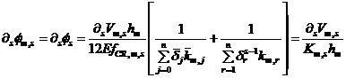
 is the stiffness of the
  level framework at response stage.
3.1. Demonstrative Example I
 and axial joint forces
  for all “i” and
  for all other“i,j”.
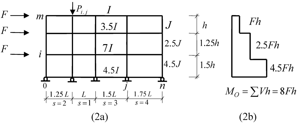
 and
and  for all “j”.
  and
and  for all other “j”. The primary purpose of this exercise is to generate a MFUR by computing the quantities
 and
and  in terms of their corresponding values
  and
and  (at roof level) respectively. The distribution of story level racking moments
  is shown in Figure 2b. The total racking moments can now be computed as 4.5
  , 7.0 , 3.5 and 1.0 for the grade, 1st, 2nd and roof level beams respectively. Since
  is uniform for each level and the quantity
  is constant for the entire frame, then for
 and
and  . And, as a result, Equation (3d) reduces to
  i.e.,
i.e., 

 and
and  By the same token, since
  simplifies Equation (4d) to
  then:
then: 

 The third level (roof) drift of the newly generated MFUR at s = 1 can now be expressed as:

 for all other “j” an
  d satisfy the Strong column-weak beam requirements, then for
  L = h,
  and
and  , Equation (6a) becomes;

 and
and  Finally, if the target drift
  is not to exceed
  where the subscript Y signifies first yield, i.e.,
  then, the design representative moment of inertia becomes
4. Story Level Elastic-Plastic Moment Response
response stage is given by;  , then by substituting for
  from Equation (2d) gives:

 and
and  become
  and
and  respectively.
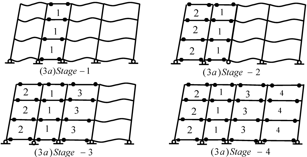
  of the system at incipient collapse, e.g., considering the plastic collapse of the moment frame of Figure 3d, through formation of plastic hinges at beam ends only, and conforming to a uniform virtual side sway of inclination θ = 1, it gives:
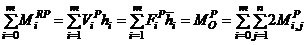
 = 2[1.0 + 3.5 + 7.0 + 4.5]
  or
or  as the ultimate load carrying capacity of the subject moment frame. However in case of MFUR, the racking equilibrium Equation of any story, Equation (2c), can also be used to achieve the same results, i.e.,
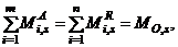
 is the plastic moment of resistance of the stiffest beam of the level framing. Since the pre-assigned uniformity ratios
  are constant for all “i”, then dividing Equations (8a) and (8b) by each other, reaffirms the condition of uniform strength at incipient collapse, i.e.,


 and
and  Substituting
  and
and 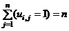 in Equation (8c) yields;
  or
or  a result already established using Equation (8a) above. This result implies that:
 MFUR with moment resisting grade beams under lateral loading of apex value
  is
is 
 ,
,  and
and  in Equation (9a) after some rearrangement, it gives the amount of force needed to produce the first set of plastic hinges in the stiffest beam of the level:
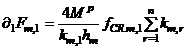
 beam (x > s) of any level can be expressed in terms of the maximum moments of the stiffest beam of that level i.e.,
  and that the sequence of formation of the plastic hinges of any level is the same as the sequence of decreasing values of stiffnesses of the beams of the same floor, then the plastic moment of resistance of the stiffest element s = 1 and moment of resistance of the next stiffest element s = 2 can be computed as
  and
and  respectively. Therefore, the balance of bending moment needed to elevate the moment of resistance of beam s = 2 to
  can be computed as
  whence the amount of additional force required to generate plastic hinges at the ends of the next stiffest beam may be generalized as:
 should add up to the ultimate load
  ,then summing both sides of Equation (9c) over all “n” iterations gives:
 and
and  in Equation (9d) leads to the previously established solution;
  .
. 4.1. Demonstrative Example II
 Given;


 J = 1.2I,
  ,
,  , h = L and
  Hence from Equation (9c):


 , and as expected
  , reconfirms the validity of the failure load formula
 for s = 1 and s = 2. After culmination of stage two, first columns j = 0 and j = 1 together at the beginning of s = 3, next columns j = 2 at the end of s = 3, then columns j = 3 and j = 4 after culmination of s = 4 lose their stiffness, due to formation of plastic hinges at their adjoining beam ends. Equation (5e) for drift increment becomes:
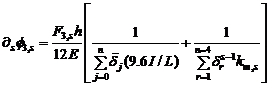
 =
= 
 =
= 
 =
=  (11b)
(11b) =
= 


 and
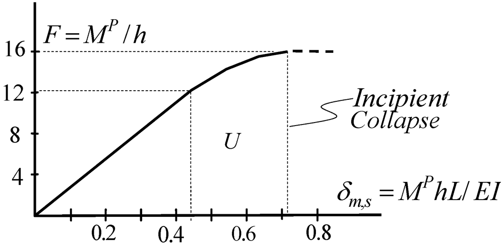
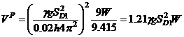
and  The combined numerical results of groups of Equations (10b) and (11b), are presented in Figure 4 as the nonlinear load-displacement relationship of the subject MFUR. Equations (5c) and (9e) together provide useful design information that neither elastic nor plastic methods of analysis can offer on their own, for instance the maximum lateral displacement of the example frame at first yield and incipient collapse can be estimated as:


5. Energy Computations For MFUR

 is constant, it would suffice to compute the internal energy of any representative level, such as that of the level, and then compute the rest by simple proportioning. The energy Equation corresponding to level “m” may be computed as:
 , then the total energy of the system may be expressed as:
 then Equation (12c) reduces to its most practical form:
 for the preceding example can be worked out via Equation (12b) or as the total area under the force-displacement (push-over) curve of Figure 4, i.e.,
  6.9512
  . Equation (12d) can then be used to compute the total internal energy of the entire system as;
 55.6096 , or in terms of ultimate values;
  and
and  at incipient collapse as;
 can also be looked upon as an indication of the capacity of the structure to absorb external energy.
 5.1.1. Stiffness Degradation
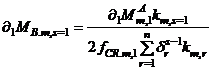
 , is a priori to estimating the momentary periods,
  , of vibrations of the system at any response stage “s”. Progressive plasticity tends to degrade the global stiffness and modify the dynamic characteristics of statically indeterminate structures under monotonically increasing lateral forces. The effects of stiffness degradation are more pronounced in MFUR since many members of similar characteristics either, fail, become inactive or develop plastic hinges simultaneously. The natural period of vibration of each stage of global loss of stiffness increases with advancing stages of loading until the structure ceases to resist external forces. As the rate of degradation of global stiffness is a function of increasing number of plastic hinges, Equations (5d) and (5e) may be rearranged to assess the gradual loss of global stiffness in terms of sequential formation of plastic hinges. may be summarized as;
 ,
, 
 ,
, 
 and
and  , where
  However, since in MFUR the distribution of story level stiffness is also a function of the story level shears, it would be reasonable to seek a simpler method of computing for the story level stiffnesses in terms of shear force ratios at different stages of loading, i.e.,
 ,
,  , etc.
 by simple, numerical proportioning e.g.,


 (13b)
(13b)


5.1.2. Period Analysis
- 1. The normalized displacement function
![Buildings 02 00107 i266]() remains unchanged throughout the loading history of the structure. In other words, loss of stiffness changes only the magnitude of lateral displacements, but not the deformed shape
remains unchanged throughout the loading history of the structure. In other words, loss of stiffness changes only the magnitude of lateral displacements, but not the deformed shape ![Buildings 02 00107 i267]() of the system.
of the system. - 2. The lateral displacement profile of the frame is a function of the single variable
![Buildings 02 00107 i216]() for all stages of loading, i.e., all displacement profiles
for all stages of loading, i.e., all displacement profiles ![Buildings 02 00107 i268]() follow the same linear shape function as their normalized displacement function
follow the same linear shape function as their normalized displacement function ![Buildings 02 00107 i269]()
- 3. Dominant mode shapes remain unchanged during formation of plastic hinges and that the coupling of modes in the inelastic range can be neglected.
- 4. The first mode of the first un-degraded stage is the most dominant mode of all response stages and that the first mode of each stage is the dominant mode of that stage.


 , where, the generalized stiffness and mass of the s
  response stage are defined as:
 and
and  respectively (14a)
 and substituting
  and
and  in Equation (14a) gives;
 and the ratio
  are constant for all “s”, then
  can be expressed in terms of the single variable, , i.e.,
 are independent of “s”, once the fundamental period of vibrations of the un-degraded structure,
  , is determined the corresponding values for each degraded stage can be worked out through simple proportioning,


 and
and  as:
as:


5.1.3. Energy Equivalency
 ), the global stiffness of the structure is in direct proportion with each story level stiffness, and that by definition, Equation (1a), the lateral displacements are a function of the single variable for all “s” then MFUR may be looked upon as SDOF systems for all practical purposes.
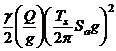
 (15)
(15) and
and  are the spectral acceleration and the energy equivalency factors respectively [10].
  and Rμ are defined as the period dependant ductility and ductility reduction factors respectively. If the quantity
  is interpreted as the seismic capacity of the structure, then the right hand side of Equation (15), may be looked upon as the seismic demand or equivalent total dynamic input energy of the system.
 5.2. Demonstrative Example III
 and
and  radians, total structural self weigh Q = 3W and un-medium degraded range fundamental period of vibrations,
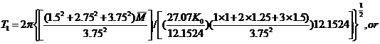
  , where,
  is the site specific design spectral response acceleration parameter. Substituting for the corresponding quantities and the total internal energies
  at first yield and
  at incipient collapse in Equation (15), and bearing in mind that
  , it gives:
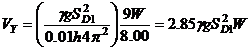
6. Conclusions
- • In MFUR selected groups of beams and columns share the same drift and Demand-capacity ratios.
- • The ultimate load carrying capacity of an (
![Buildings 02 00107 i159]() MFUR with moment resisting grade beams under lateral loading of apex value
MFUR with moment resisting grade beams under lateral loading of apex value ![Buildings 02 00107 i160]() is
is ![Buildings 02 00107 i161]()
- • The ratio of total internal energy of MFUR to that of anyone of its levels, such as the roof, is equal to the ratio of the global overturning moment to the overturning moment of that (roof) level.
- • The ratio of stiffness of any two floors of an MFUR is proportional to the ratio of shear forces of the two levels multiplied by the inverse ratio of their heights.
- • MFUR may be treated as statically determinate, SDOF structures.
References
- Goel, S.C.; Liao, W.; Bayat, M.R.; Chao, S. Performance-based plastic design method for earthquake resistant structures. Struct. Des. Tall Spec. Build. 2010, 19, 115–137. [Google Scholar]
- Mazzolani, F.; Pilosu, V. Theory and Design of Seismic Resisting Moment Frames; Taylor & Francis: Oxford, UK, 1996. [Google Scholar]
- Grigorian, M.; Grigorian, C. Performance control for seismic design of moment frames. J. Construct. Steel Res. 2011, 67, 1106–1114. [Google Scholar] [CrossRef]
- Grigorian, M.; Grigorian, C. Recent developments in plastic design analysis of steel moment frames. J. Construct. Steel Res. 2012, in press. [Google Scholar]
- Grigorian, M. On the lateral response of regular high-rise frames. Struct. Des. Tall Spec. Build. 1993, 2, 233–252. [Google Scholar] [CrossRef]
- Grigorian, M.; Grigorian, C. Preliminary minimum weight design of moment frames under lateral loading. AISC Eng. J. 1988, 25, 129–136. [Google Scholar]
- Beedle, L.S. Plastic Design of Steel Frames; John Wiley & Sons: Hoboken, NJ, USA, 1985. [Google Scholar]
- Neal, B.G. The Plastic Methods of Structural Analysis; Chapman & Hall Ltd.: London, UK, 1963. [Google Scholar]
- Housner, G.W. Limit Design of Structures to Resist Earthquakes. In Proceedings of the 1st World Conference on Earthquake Engineering, Berkeley, CA, USA, 1956; Earthquake Engineering Research Institute (EERI): Berkeley, CA, USA, 1956. [Google Scholar]
- Chopra, A.K.; Goel, R.K. Capacity-demand diagram methods for estimating seismic deformations of inelastic structures. Earthq. Spectra 1999, 15, 637–655. [Google Scholar] [CrossRef]
Appendix I
 , consider the ratio of internal energy of any level “i” to that of the roof level “m”, i.e.,
 , then
  Substituting for
  in Equation (16a), it gives
  The total internal energy of the system may also be computed as the sum of internal energies of the “m” individual levels, i.e.,
Appendix II
 , and for the roof level as
  . Observing that by definition,
  , then the division (
  gives;
© 2012 by the authors; licensee MDPI, Basel, Switzerland. This article is an open-access article distributed under the terms and conditions of the Creative Commons Attribution license (http://creativecommons.org/licenses/by/3.0/).
Share and Cite
Grigorian, M.; Grigorian, C.E. An Introduction to the Methodology of Earthquake Resistant Structures of Uniform Response. Buildings 2012, 2, 107-125. https://doi.org/10.3390/buildings2020107
Grigorian M, Grigorian CE. An Introduction to the Methodology of Earthquake Resistant Structures of Uniform Response. Buildings. 2012; 2(2):107-125. https://doi.org/10.3390/buildings2020107
Chicago/Turabian StyleGrigorian, Mark, and Carl E. Grigorian. 2012. "An Introduction to the Methodology of Earthquake Resistant Structures of Uniform Response" Buildings 2, no. 2: 107-125. https://doi.org/10.3390/buildings2020107
APA StyleGrigorian, M., & Grigorian, C. E. (2012). An Introduction to the Methodology of Earthquake Resistant Structures of Uniform Response. Buildings, 2(2), 107-125. https://doi.org/10.3390/buildings2020107