
Large Concrete Rubble as a New Structural Construction Material: Opportunities and Digital Processes for Load-Bearing Walls


Abstract
1. Introduction
1.1. State of the Art
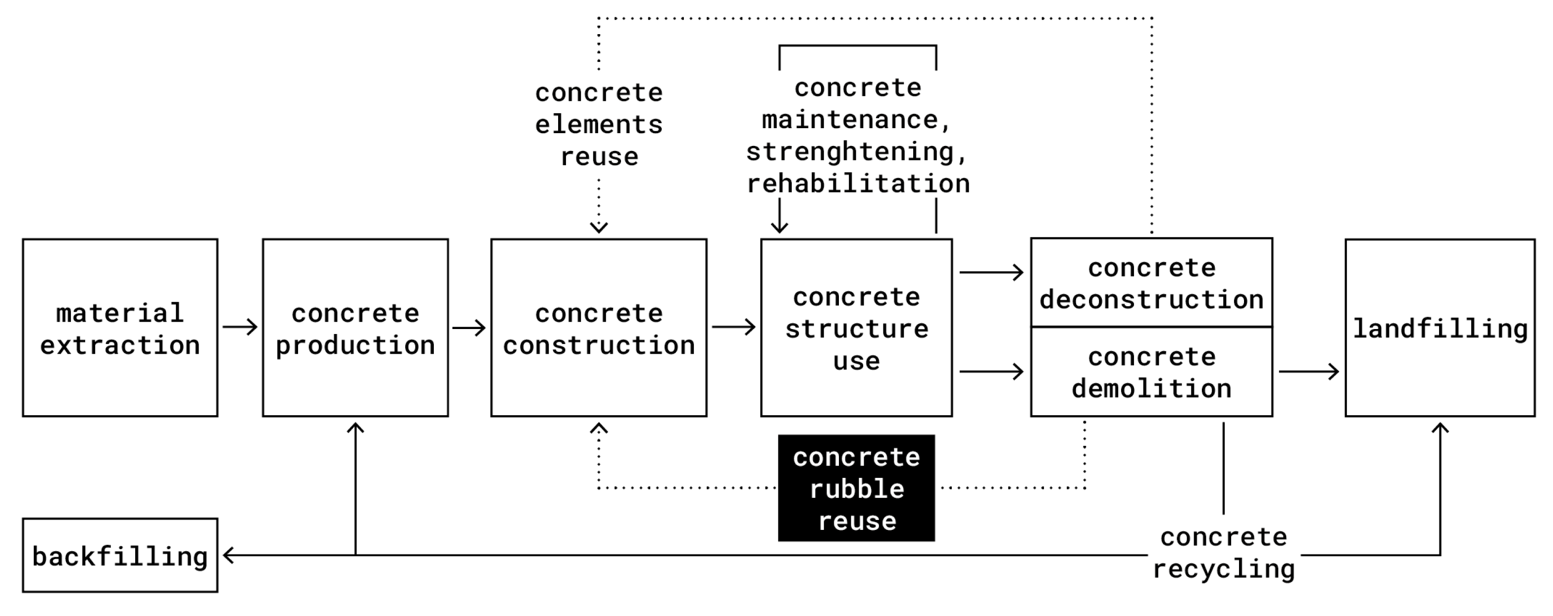
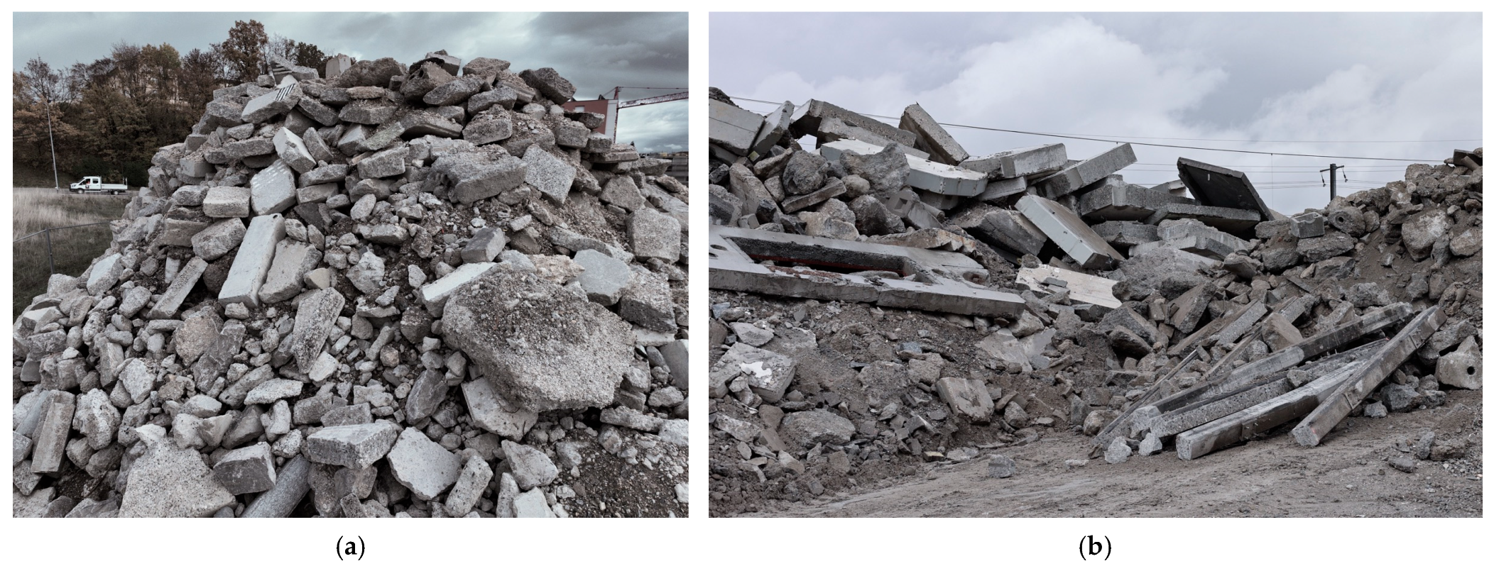
1.1.1. Concrete Rubble Occurrence
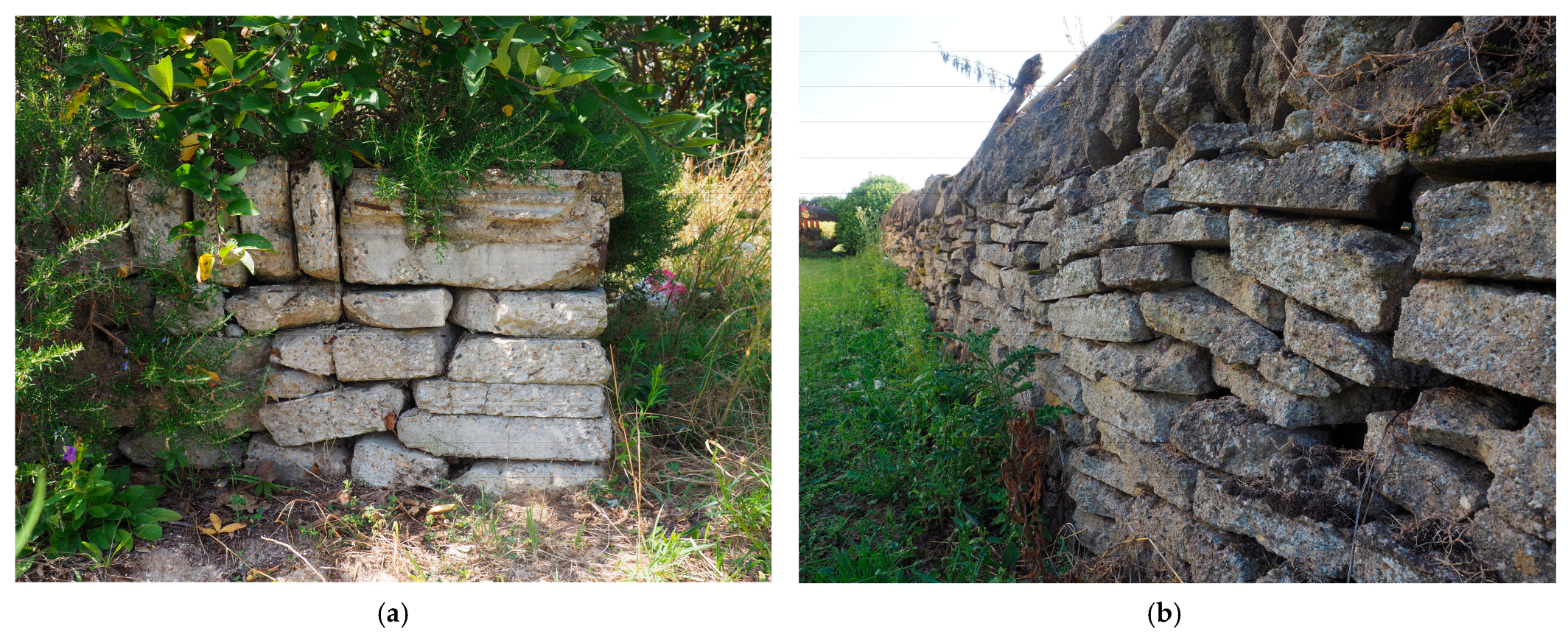
1.1.2. Reusing Concrete Rubble
1.2. Problem Statement
1.2.1. Research Gaps
- There are missing insights on the functional, economic, environmental, structural and architectural opportunities and limitations offered by the reuse of irregular concrete rubble as a base material for the construction of new structures.
- The productivity and structural performance of single-leaf masonry walls from large flat concrete rubble are unknown. Moreover, details about their construction precision, energy consumption, and environmental impact are missing.
- There is a lack of accessible, scalable and resilient digital construction processes for reusing concrete rubble with unique geometries in new structures.
1.2.2. Industry Challenges
- Value deficiency. Currently, the construction industry sees marginal value in building structures using large, flat, unaltered concrete rubble from demolition, especially because of the lack of productivity data from physical experimentations. Thus, the challenge is to convince the industry to embrace a new method without precedents.
- Workers’ safety. The non-standard geometry, the heterogeneity and the weight of concrete rubbles render their handling unergonomic and dangerous. Risks of accidents are accentuated as current lifting tools are not perfectly suited. The challenge is thus to implement a safe and ergonomic construction process to handle such pieces.
- Tools complexity. The current state of the art suggests the need for complex and expensive machines operated by experts. The challenge lies in the development of innovative tools that can be easily understood and maintained by non-expert construction workers.
- Space limitation. Logistically, the use of irregular pieces requires space for storage, analysis and sorting in anticipation of their assembly, while construction sites can be constrained in space. The challenge is, hence, to construct in a small space despite the need for extensive space. Additionally, constructing thick building structures implies less internal space for similar external boundaries, in turn negatively affecting the economic value of the building. The related challenge is to construct slender structures from a multiplicity of elements.
- Stock-based uncertainty. There is no upfront guarantee of feasible construction based on a small stock of concrete rubble or on-the-fly sourcing. In addition, rubble pieces can deteriorate or break, potentially compromising construction. Additionally, the structural performance of such applications depends on concrete rubble from demolition, whose geometrical and mechanical properties are also uncertain. The challenge is thus to design and construct load-bearing structures with such unknowns.
- Competitiveness. For the proposed process to be scalable, it must offer advantages, including speed and environmental impact, which is notably driven by mortar quantity.
1.3. Objectives
- Assess the opportunities and limitations of reusing concrete rubble in the construction of new structures (addressing research gap 1).
- Develop, implement, and test a safe, accessible, scalable, and resilient design-to-construction process by leveraging the benefits of digital tools to make low-carbon and sound structures from heavy, variable, and non-standard concrete rubble (addressing research gap 3 and industry challenges).
- Provide insights into the construction precision, productivity, and energy consumption of the developed process (addressing research gap 2).
- Benchmark the environmental saving potential, assess the structural potential of the resulting structure, and identify pathways to increase them (addressing research gap 2).
1.4. Scope
1.5. Content Organisation
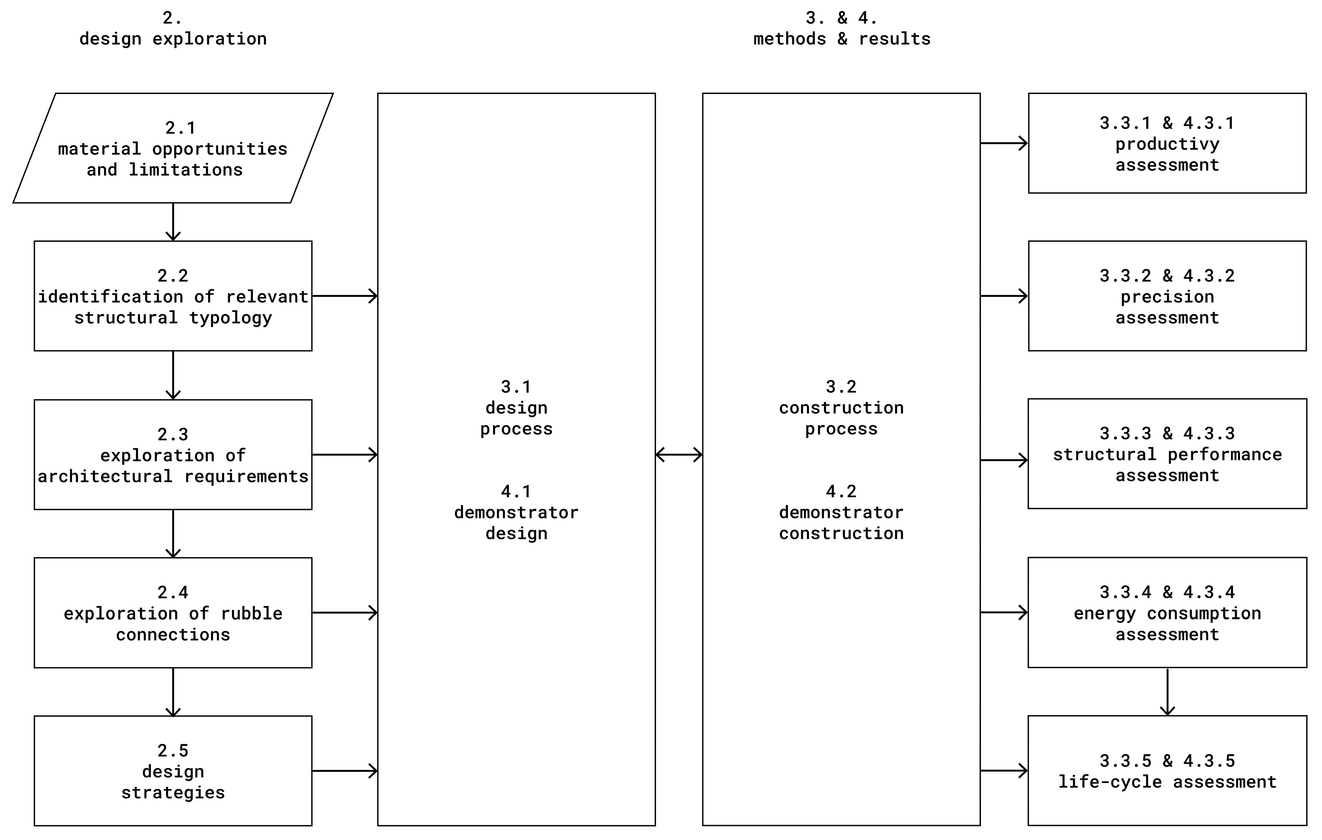
2. Design Exploration
2.1. Opportunities and Limitations for Concrete Rubble
- Cheap. Concrete rubble is a waste offered to recycling centres, with regular compensation to evade the high cost of landfilling. Consequently, the remaining costs to obtain concrete waste are exclusively related to logistics, which can be optimized.
- Low carbon. Any upcycling approach of concrete waste prior to recycling it by crushing leverages embedded emissions and avoids new ones.
- Local. Recycling centres are evenly distributed to reduce transport distance from demolition sites, providing local, abundant, and permanent sources of concrete rubble. Reusing rubble on or near demolition sites further reduces transport emissions.
- Reliable. Reusing the outcome of traditional demolition avoids the costly disturbance of deconstruction sites for sourcing reclaimed materials, the major drawback of component reuse.
- Sturdy. Concrete fragments benefit from the high isotropic compressive resistance of old concrete.
- Compliant. The reconfiguration of small concrete pieces into large structural elements allows a large diversity and freedom in new positioning and structure dimensions.
- Stone substitute. The compressive resistance and the mineral composition of small concrete rubble enable its direct use as stone, alleviating raw material extraction.
- Massive. Due to the preservation of density, concrete rubble pieces retain the thermal and acoustic attributes of concrete, valued for its mass.
- Distinctive. Despite heterogeneity, the similar geometric features of concrete rubble can be leveraged in the design: a significant part of concrete rubble possesses flat faces, often two or more, and straight edges.
- Compressive only. Demolition causes sectioning of rebars if any, resulting in degradation of tensile, shear, and bending capacity.
- Irregularity. The non-standard geometry of concrete rubble (broken edges and faces) is challenging to be described using primitives.
- Variable. Recycling centres collect rubble pieces from various sites, providing non-uniform properties and geometries. Using debris from a unique demolition site partly alleviates this drawback.
- Heavy. Due to the high density of concrete, manipulating rubble units by hand limits the maximum usable size of rubble pieces to a small proportion of total waste.
- Hard. The strength of concrete rubble pieces also makes it long to cut or drill.
- Uncertain. Assessing the properties of concrete rubble for reuse can be challenging due to uncertainties in fabrication, use, and dismantlement. These uncertainties include concrete composition and strength, wearing, previous exposition, and dismantlement method and care.
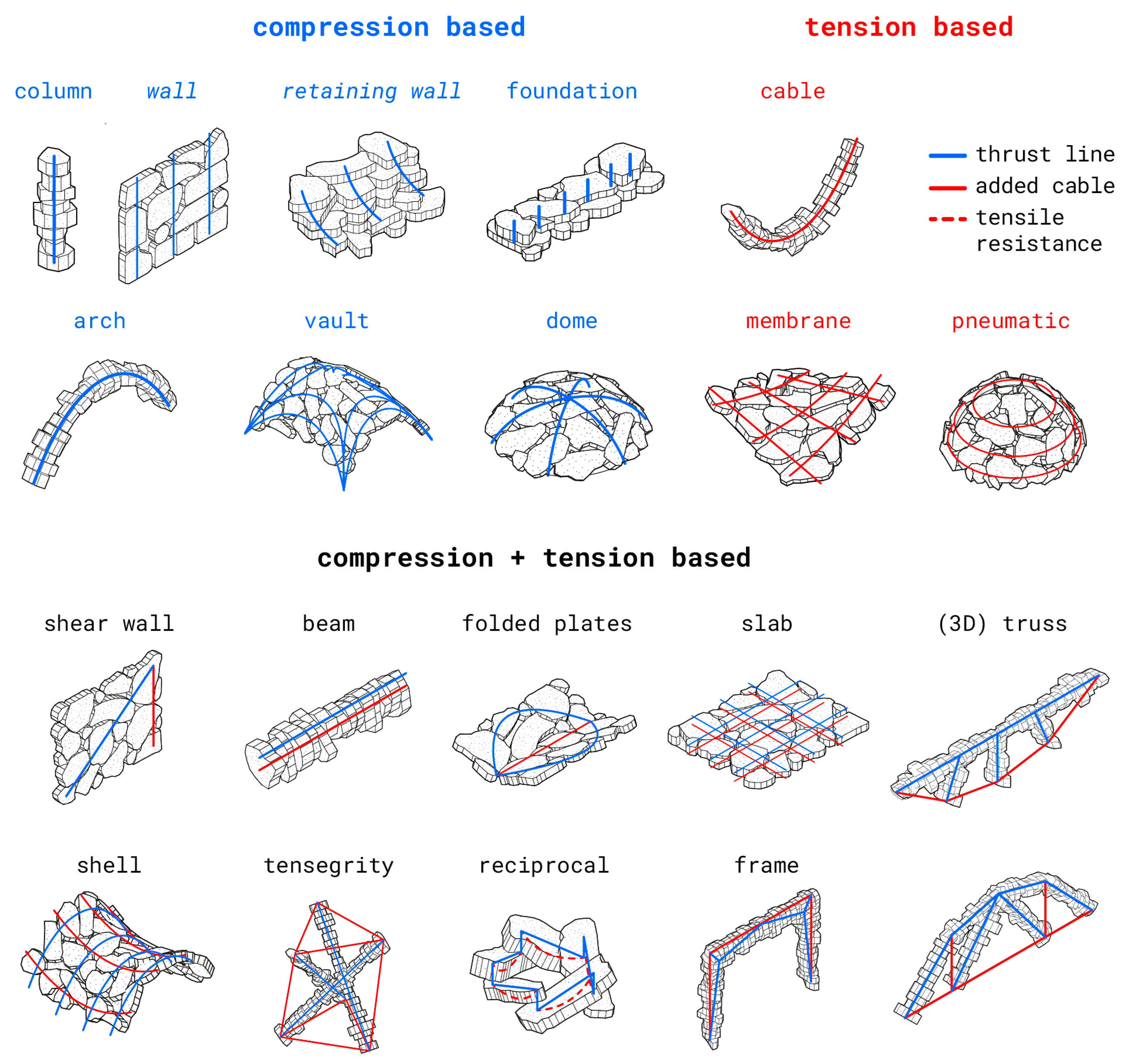
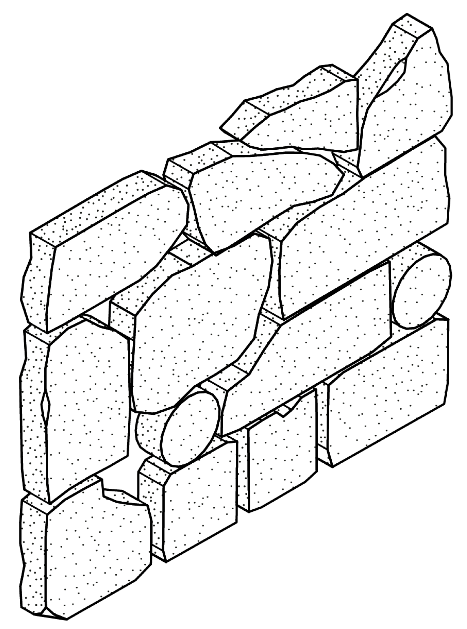
2.2. Identification of Relevant Structural Typology
2.3. Exploration of Architectural Parameters
- Slenderness. For space-saving structures in new buildings.
- Flatness on both sides. For ease of integration of other building layers or the fixation of technical systems.
- Rectangular bounding geometry. For ease of connection with other structural components.
- Compressive resistance. The load-bearing capacity should be sufficient for mid-rise residential buildings.
- Low environmental impact.
- Visual harmony. Aesthetically pleasing composition.
- Airtightness. For thermal performance in building applications.
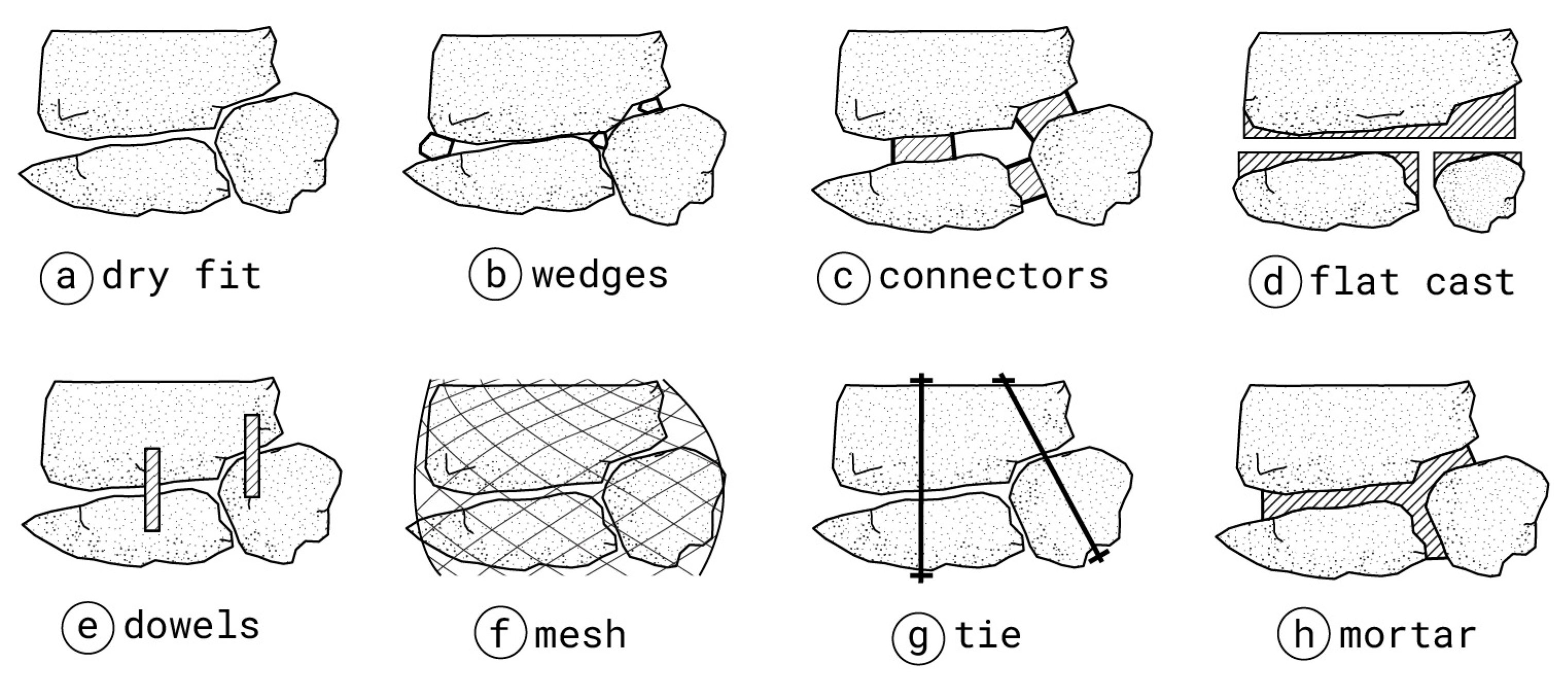
2.4. Exploration of Rubble Connections
2.5. Design Strategies
- Efficiency. Stable structural configuration should be found using irregular pieces.
- Integrity. The geometry of each rubble unit must remain largely unaltered.
- Resilience. New design options must be possible if the assembly of a concrete fragment is compromised.
- Flexibility. The stock size, diversity and renewal must not prevent design solutions.
- Constriction. Space needed for scanning, handling, and storing must be minimized.
2.5.1. Masonry Rules
2.5.2. Relevance of Digital Tools
3. Methods
3.1. Design Process
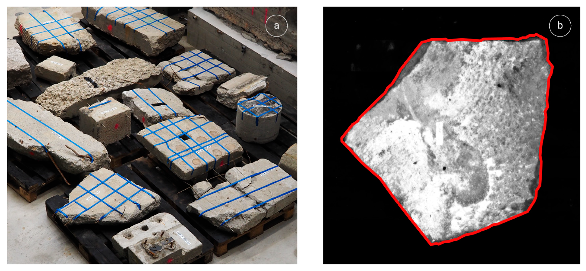
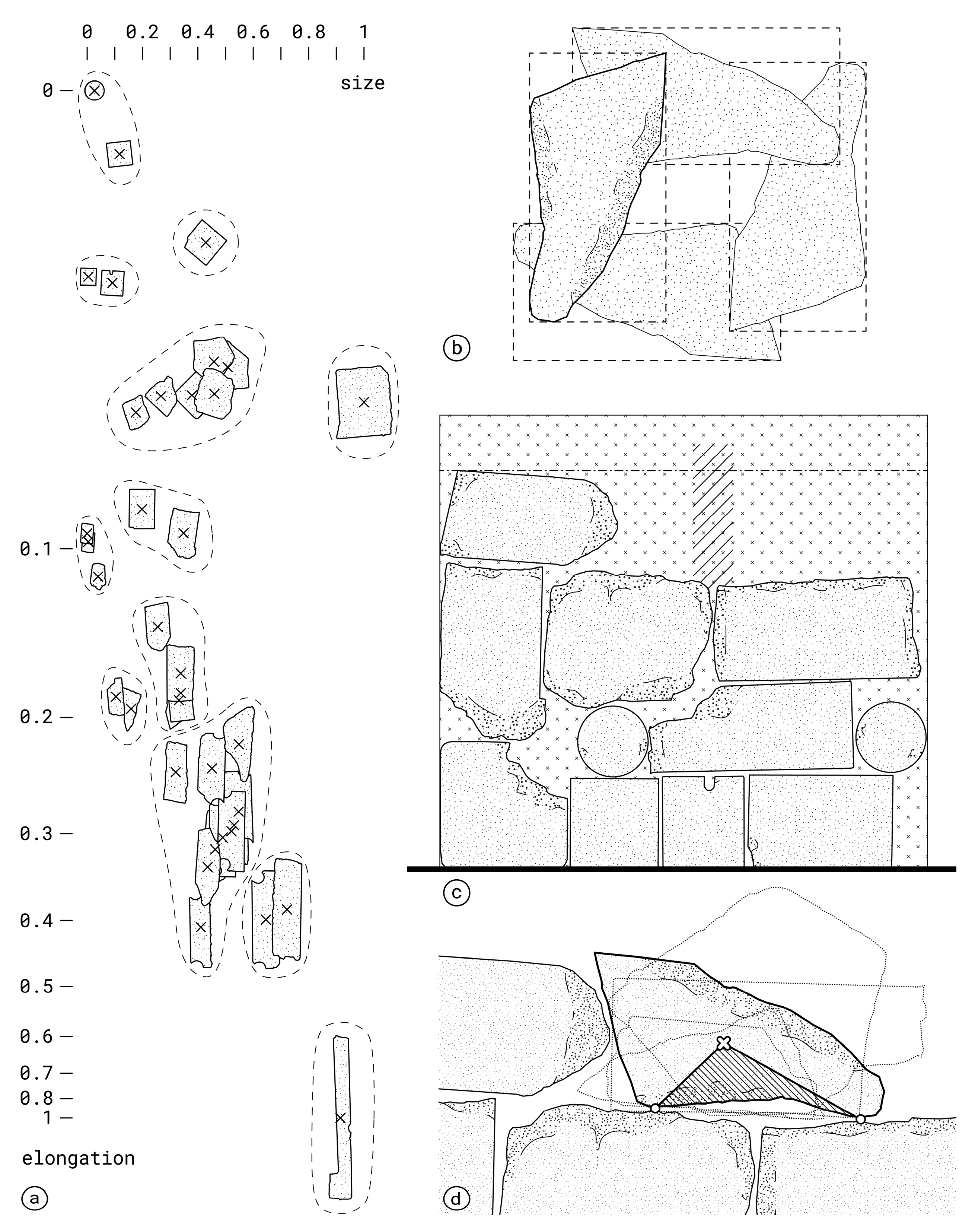
3.1.1. Geometry Acquisition
3.1.2. Stacking Design
3.2. Construction Process
3.2.1. Construction Principles
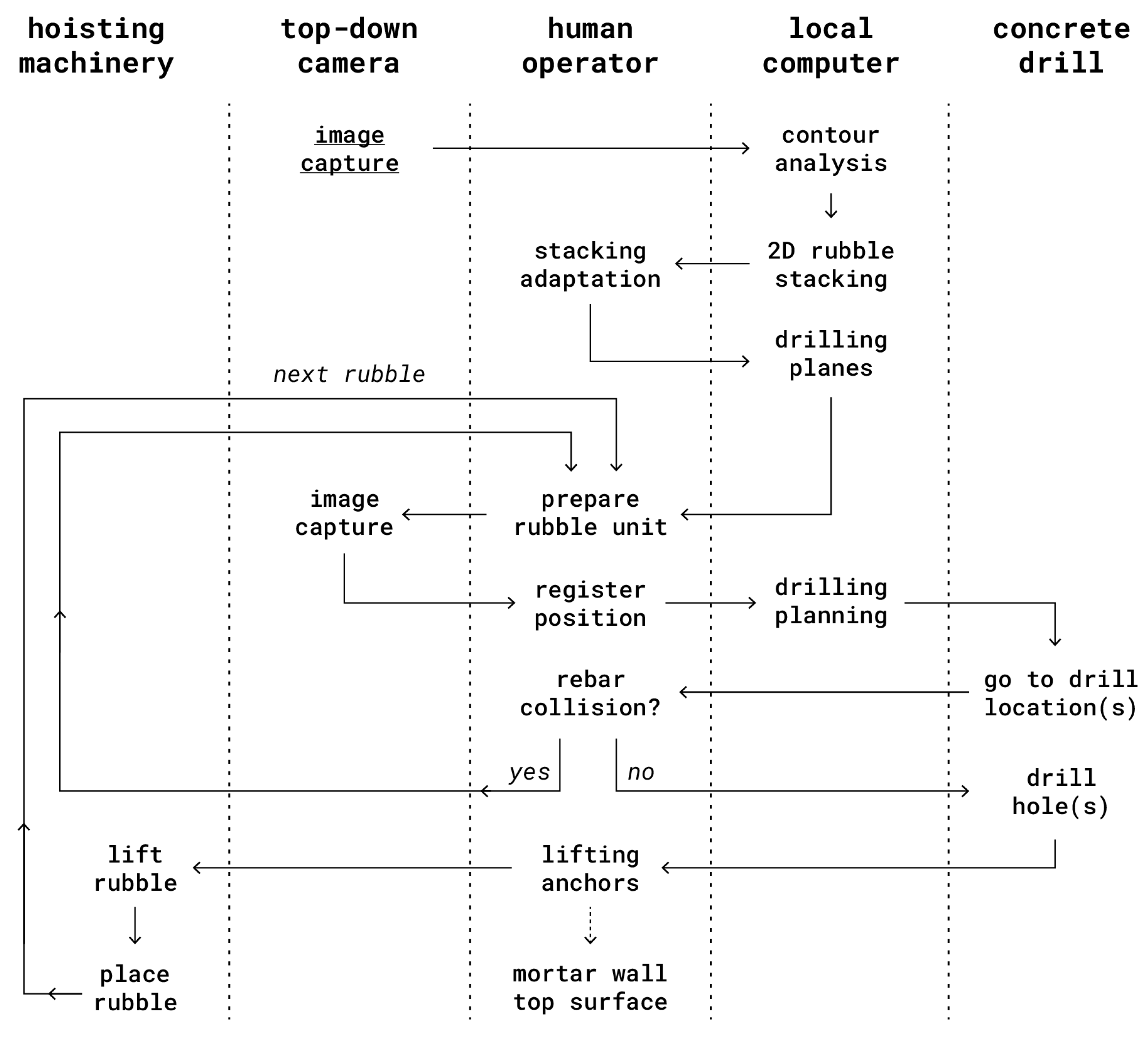
- Acquiring the irregular geometry of accessible rubble pieces. The top-down pictures are analysed using edge detection or image segmentation.
- Choosing a stacking solution and manually improving it if necessary. Improvements include decreasing void area or adjusting orientation to maximize stability during rubble placement.
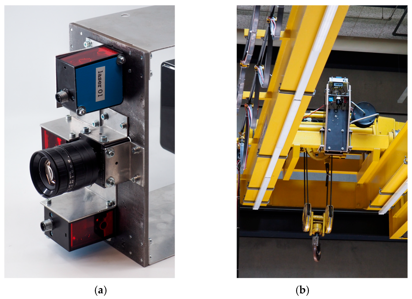
- Positioning the (next) rubble unit in the processing area and registering its location using another top-view photo. Position the concrete hammer drill in front of the lifting point(s) location(s).
- Checking for rebar collision at the drilling point with a metal detector. In case of collision, slightly adapt the position of the lifting points and check collisions until it is satisfactory.
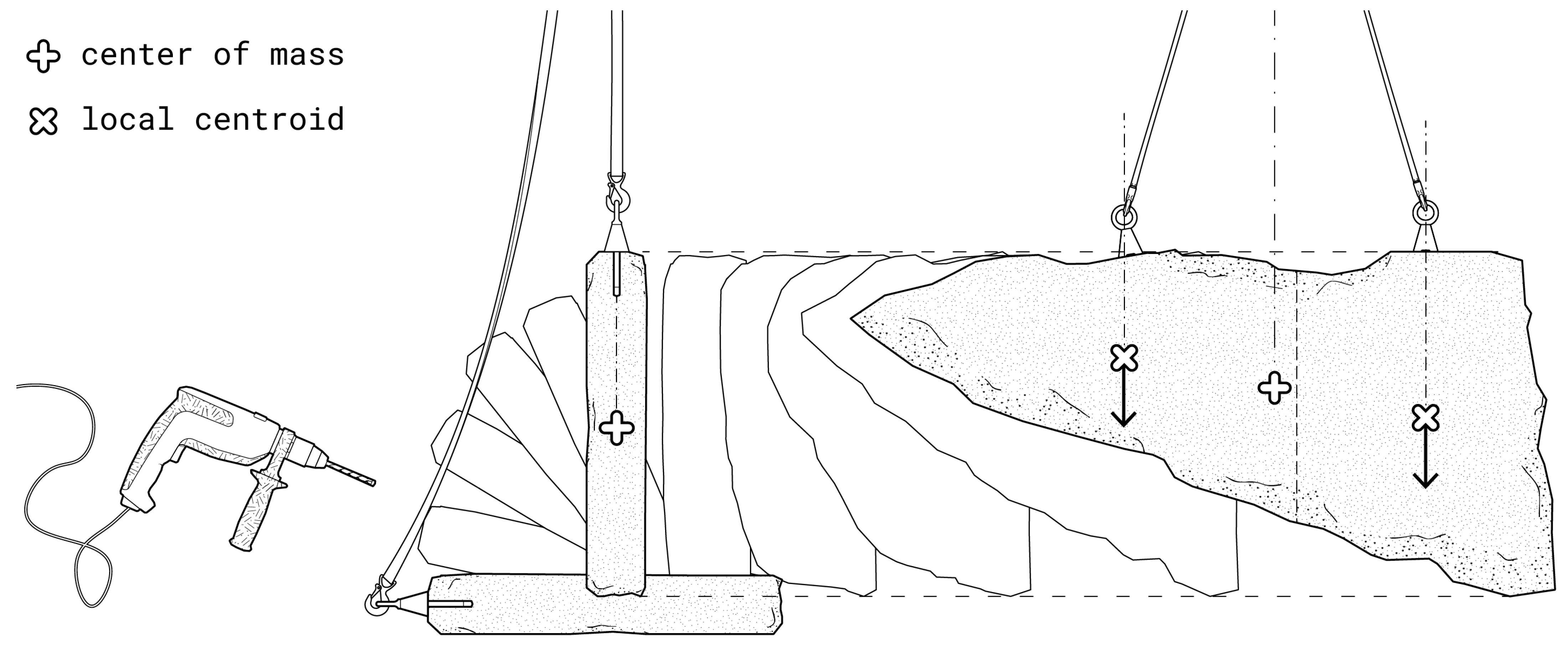
- Drilling of the lifting points. Such drilling operations can also be achieved through augmented drilling, laser-guided drilling, or robotic drilling (more details available at the end of the subsection).
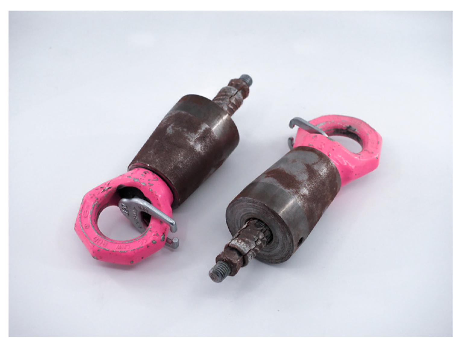
- Inserting lifting eyes in drilled holes.
- Lifting and positioning using any hoisting machinery. Based on digital position instruction from the stacking solution and the position of the rubble units on the ground, the placement of each rubble can be achieved onsite with a tower crane, or offsite with an overhead crane of the prefabrication facility.
- Breaking off any protruding part using a jackhammer or bolt cutter. As this can only be executed when the rubble is flat on the ground for safety concerns, it is best to perform such adjustments before lifting. When the protruding parts remain undetected before placement, delicate manoeuvres to reposition the rubble unit on the ground are needed.
- Cleaning the rubble unit with water to remove dust and saturate the surface to ensure optimal mortar bond, as broken concrete absorbs more water than crushed stone [59].
- Aligning rubble front faces to formwork. A localized climbing formwork of the desired planar dimensions of the wall is used to align rubble units against the front face manually. It ensures the visual quality of the final structure and optimizes flatness and planarity.
- Controlling horizontal positioning using a ruler on the formwork and coordinates as the digital intersection between the rubble outlines and the formwork.
- Grounding using fast-setting mortar and wedges from concrete debris. To reach out of plane stability which is critical when stacking flat pieces on their thin faces, special care is taken by the human operator to ensure complete stability and grounding in mortar before releasing the lifting hooks. The tolerance of mortar discards the need for altimetric and rotational position control. Moreover, smaller mortar joints lead to better compressive resistance, but must remain thicker than 10 mm for them to play a structural role [38]. This is visually ensured while laying the concrete rubble pieces.
- Filling masonry gaps and backside voids. The large flat rubble pieces have variable thicknesses when sourced from recycling centres, leading to variable voids in the backside of the considered wall. Lighter rubble pieces and concrete gravel are thus manually placed in the remaining void to reduce its volume. The localized formwork encapsulating the contact area between two courses of rubble masonry acts as the boundary of the voids to be filled. When sourced from demolition sites directly, concrete rubble pieces have more similar thicknesses, alleviating the problem of filling the void in the back.
- Pouring fluid mortar. Liquid mortar is poured into remaining interstitial voids to obtain airtightness and joints with flat sides along the planes of the wall. Adding 3 mm gravel in the mix further minimizes mortar needs but degrades mortar viscosity and reach of small voids. Vibrating mortar is critical to fill voids. The mortar is poured below the top side of the large rubble pieces, keeping a rough surface to improve adhesion with the next course above.
- Rising climbing formwork. Once a course is completed and the mortar has hardened, the lightweight formwork is raised around the next horizontal joint and the procedure is repeated. To obtain a flat top, mortar is poured over the rubble pieces only in the last course.
- Ensuring airtightness. Once the localised formwork is removed, void might remain in between rubble pieces. These are filled again with smaller rubble pieces and mortar to obtain airtightness.
3.2.2. Construction Tools
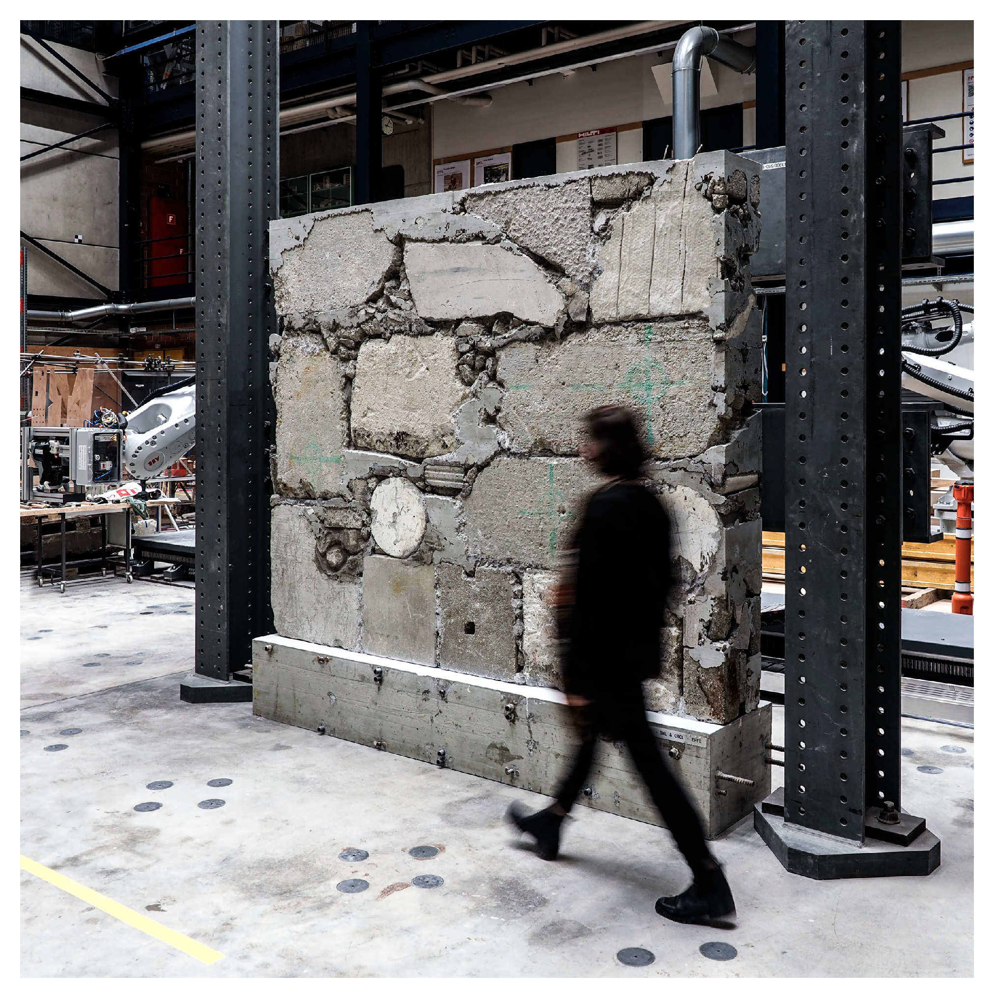
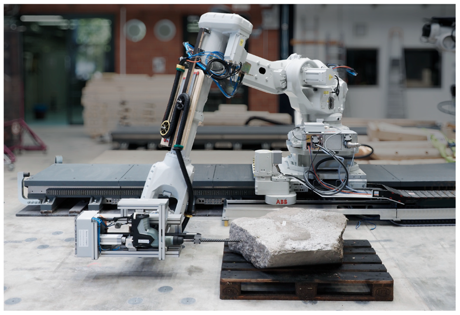
3.2.3. Demonstrator Construction
3.3. Performance Assessment
3.3.1. Productivity Assessment
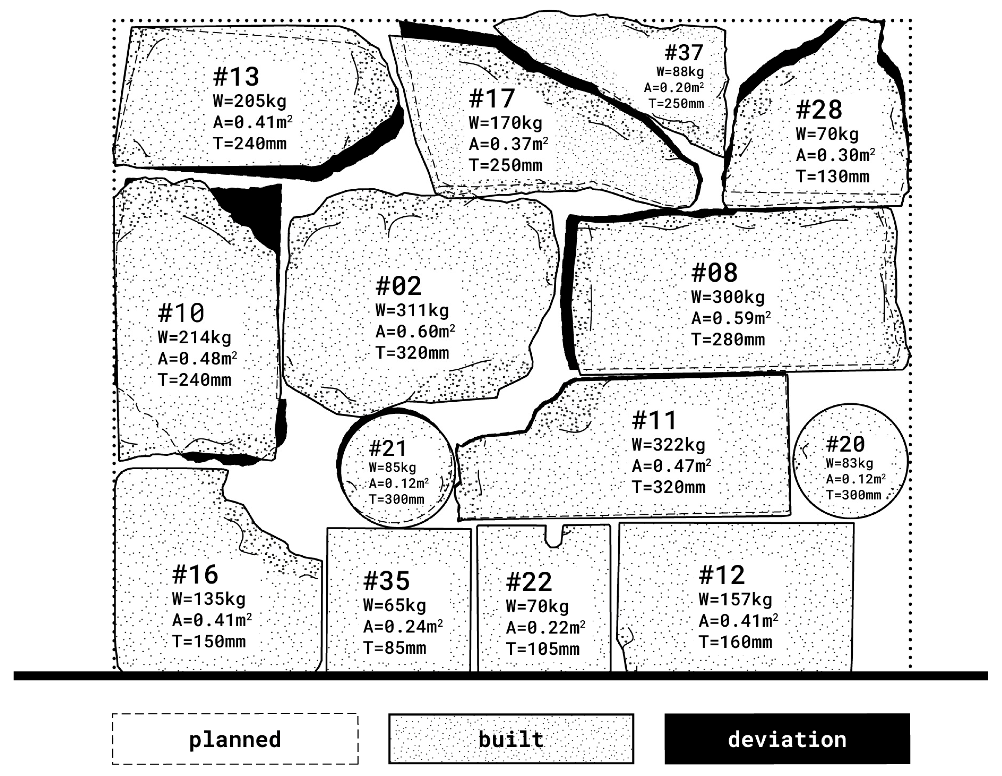
3.3.2. Construction Precision Assessment
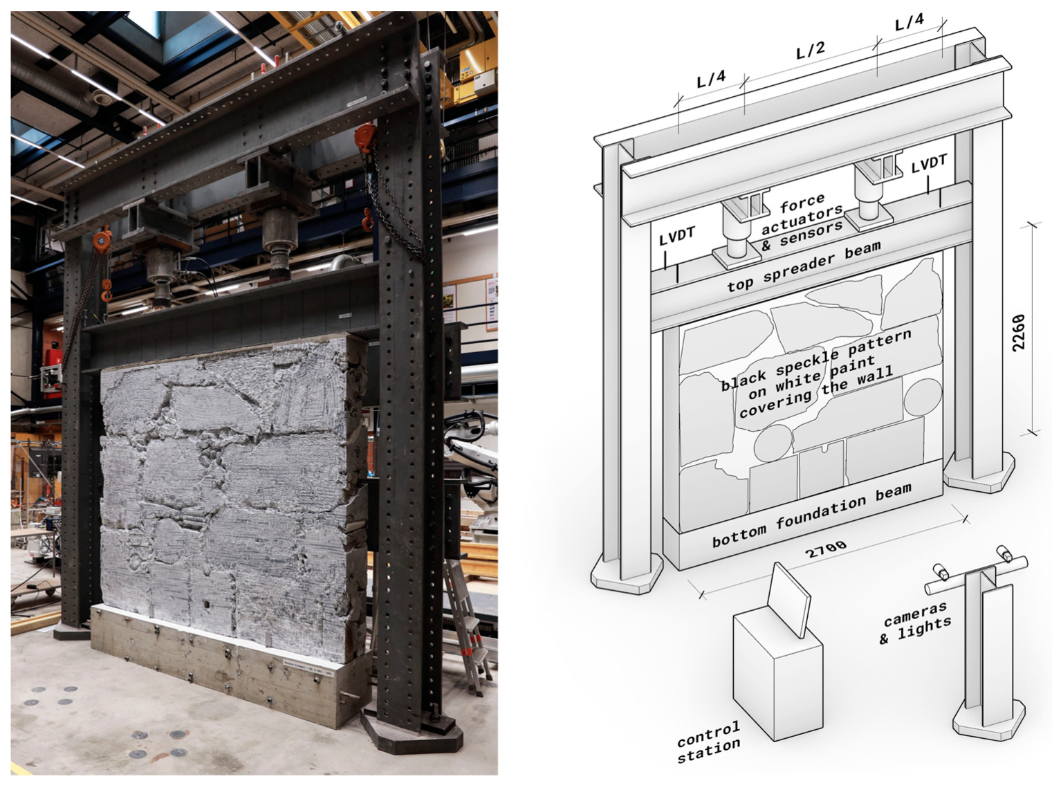
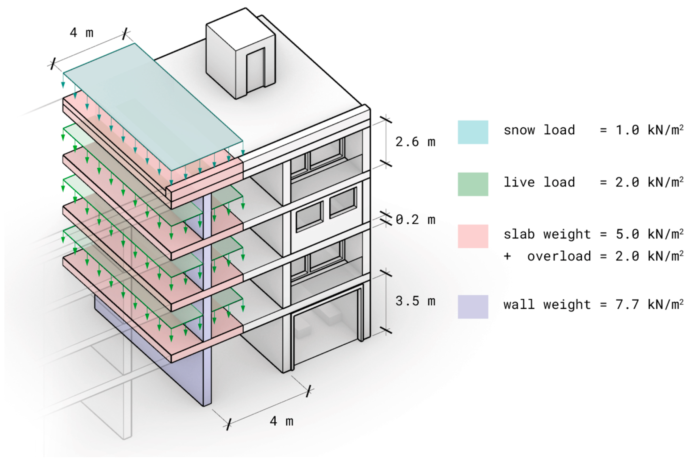
3.3.3. Structural Assessment
3.3.4. Energy Consumption Assessment
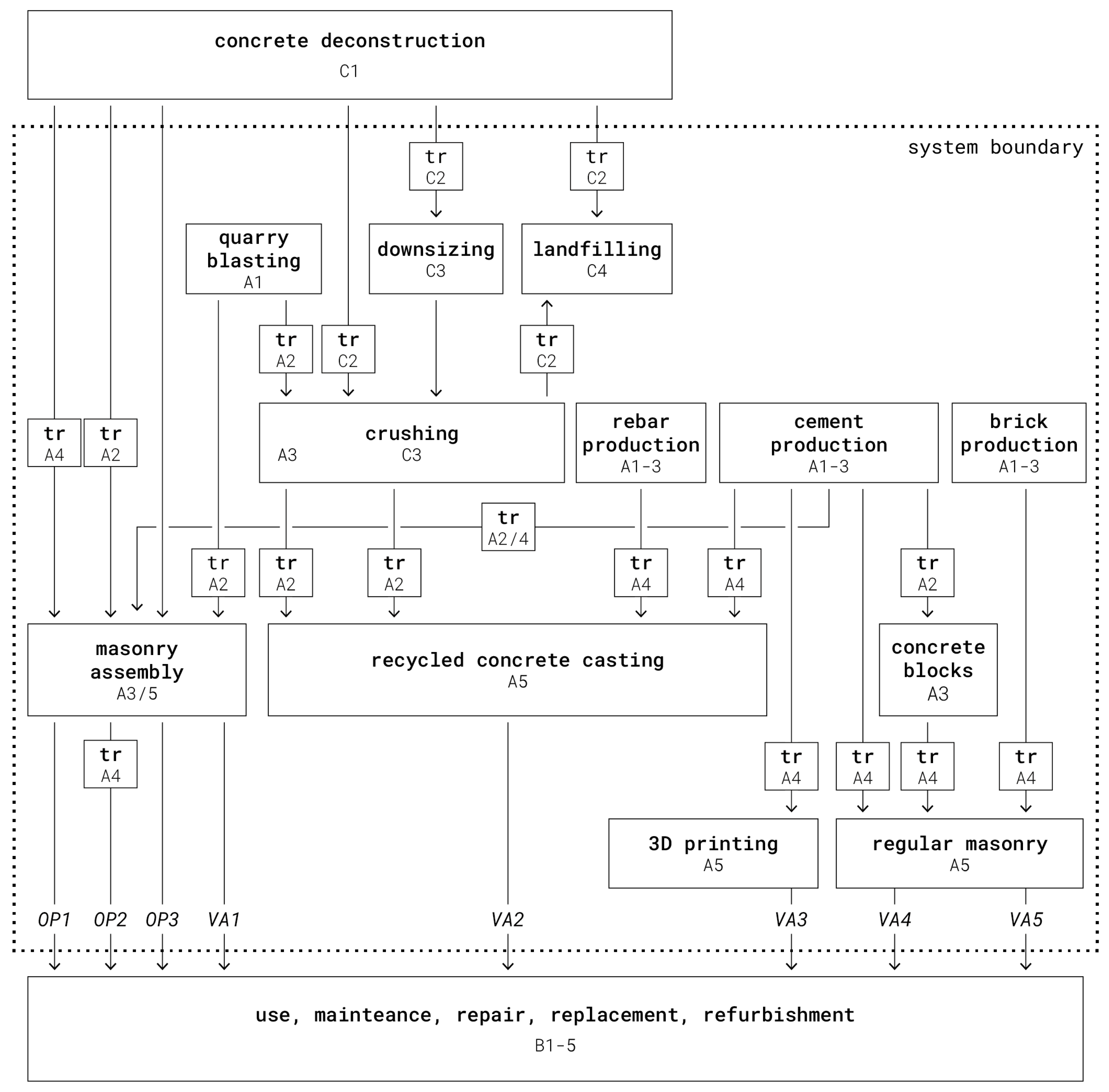
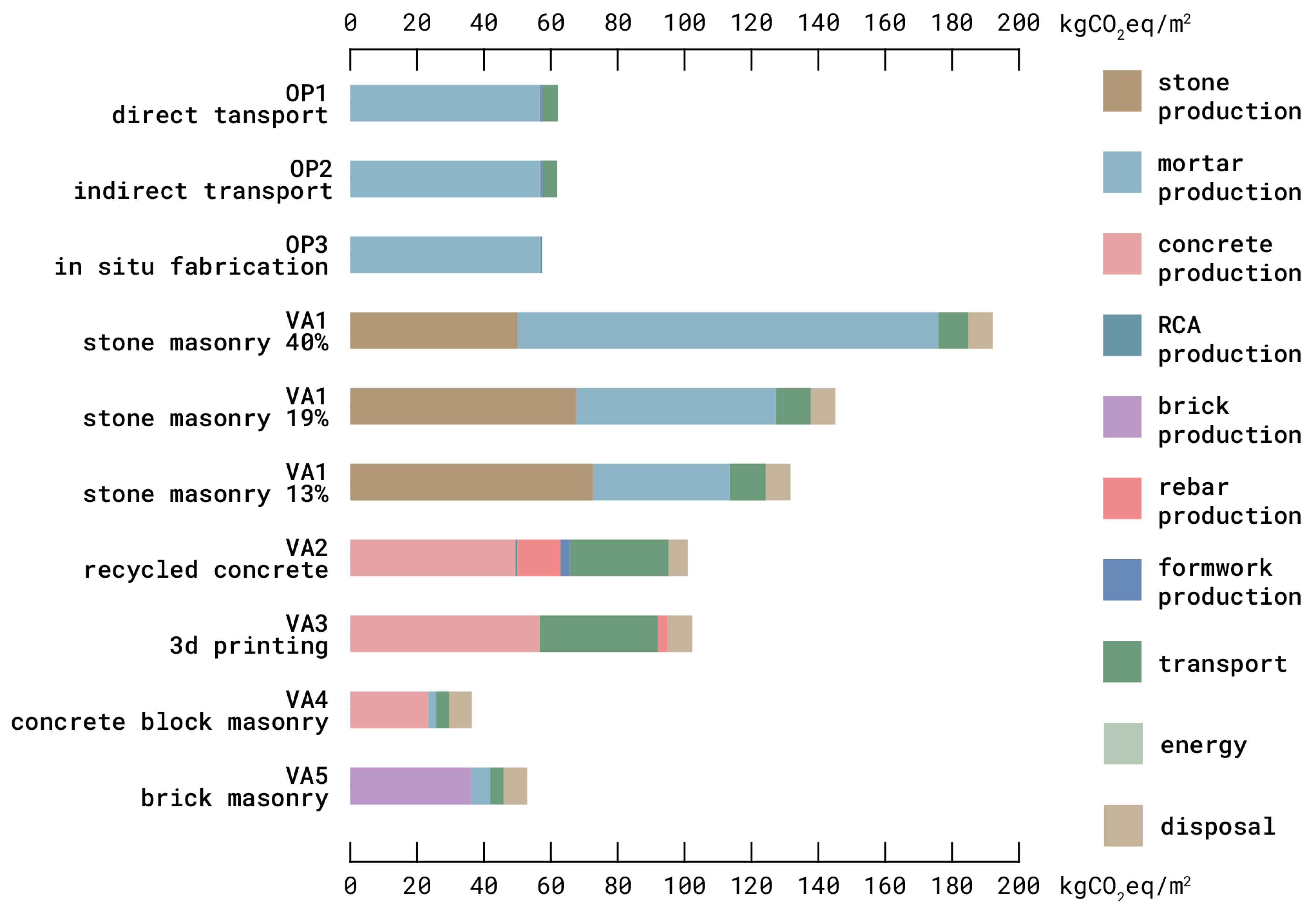
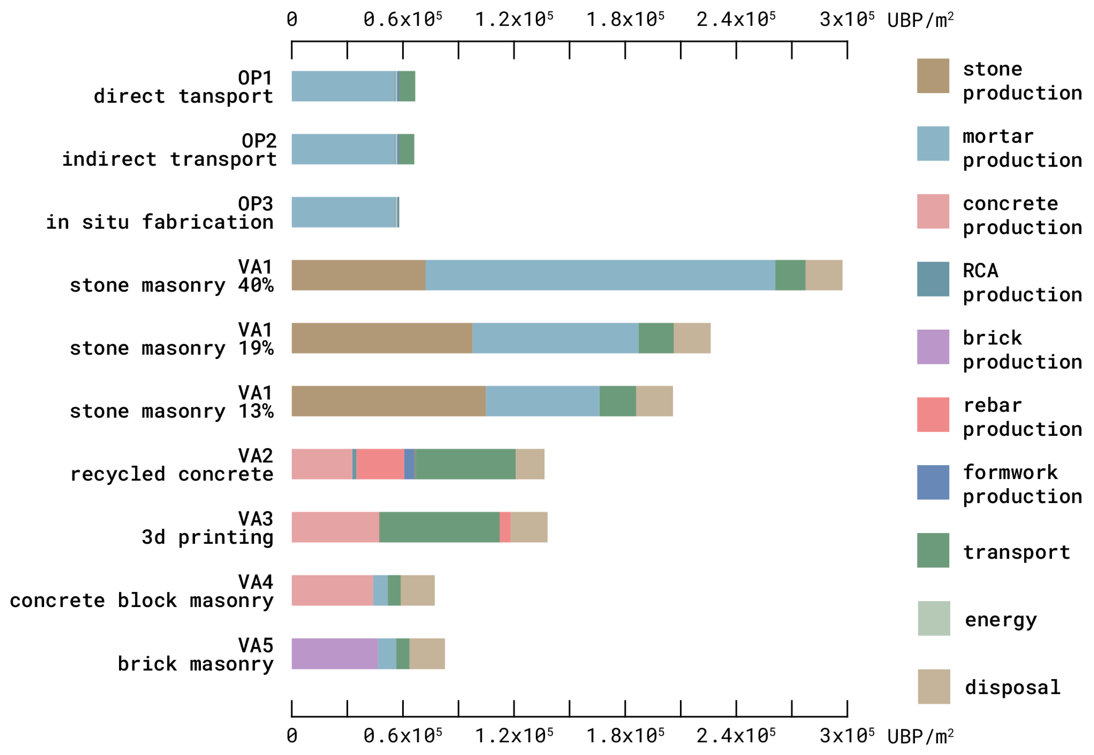
3.3.5. Environmental Impact Assessment
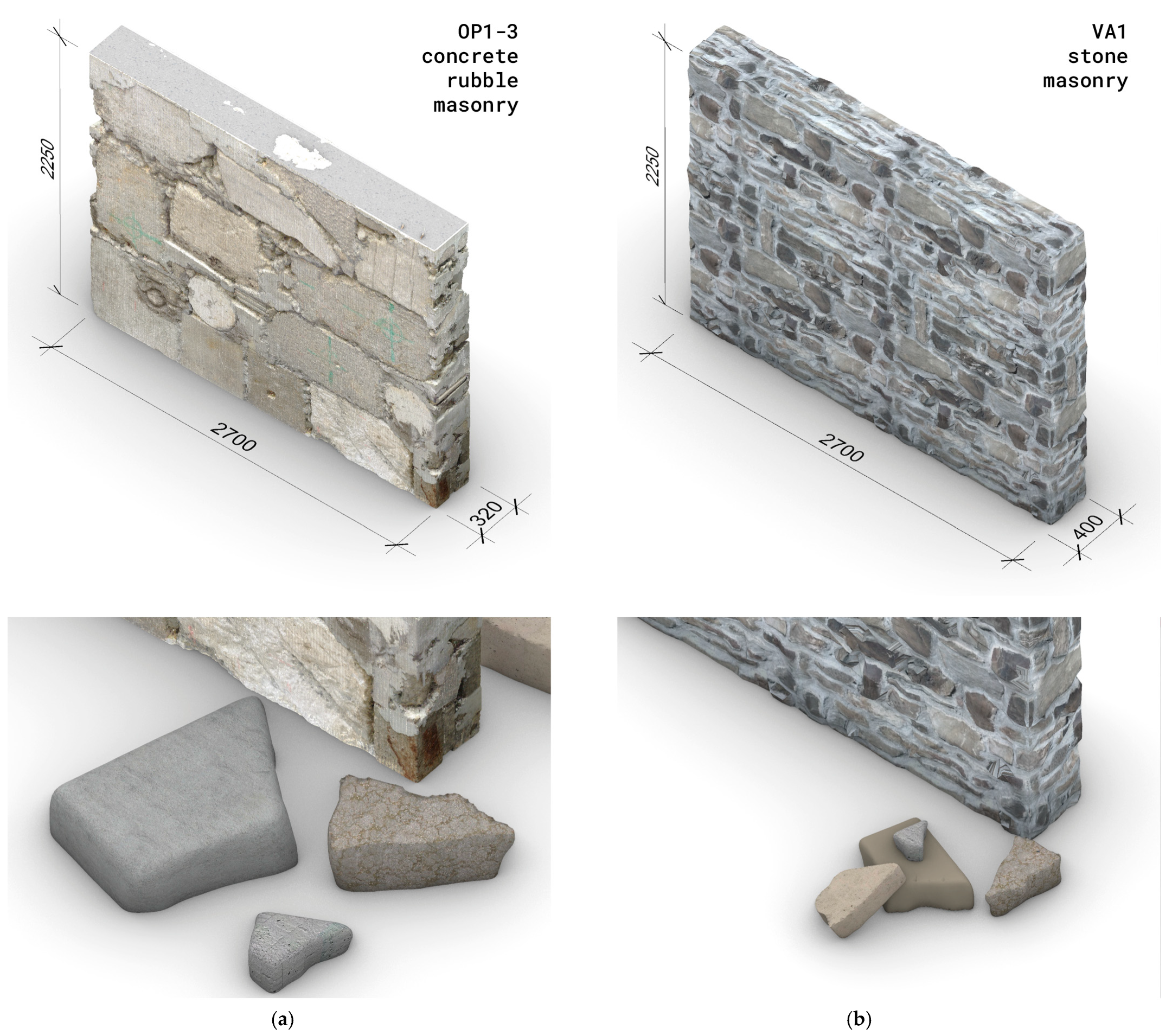
- an irregular stone masonry structure made of mortar and local sandstone (VA1);
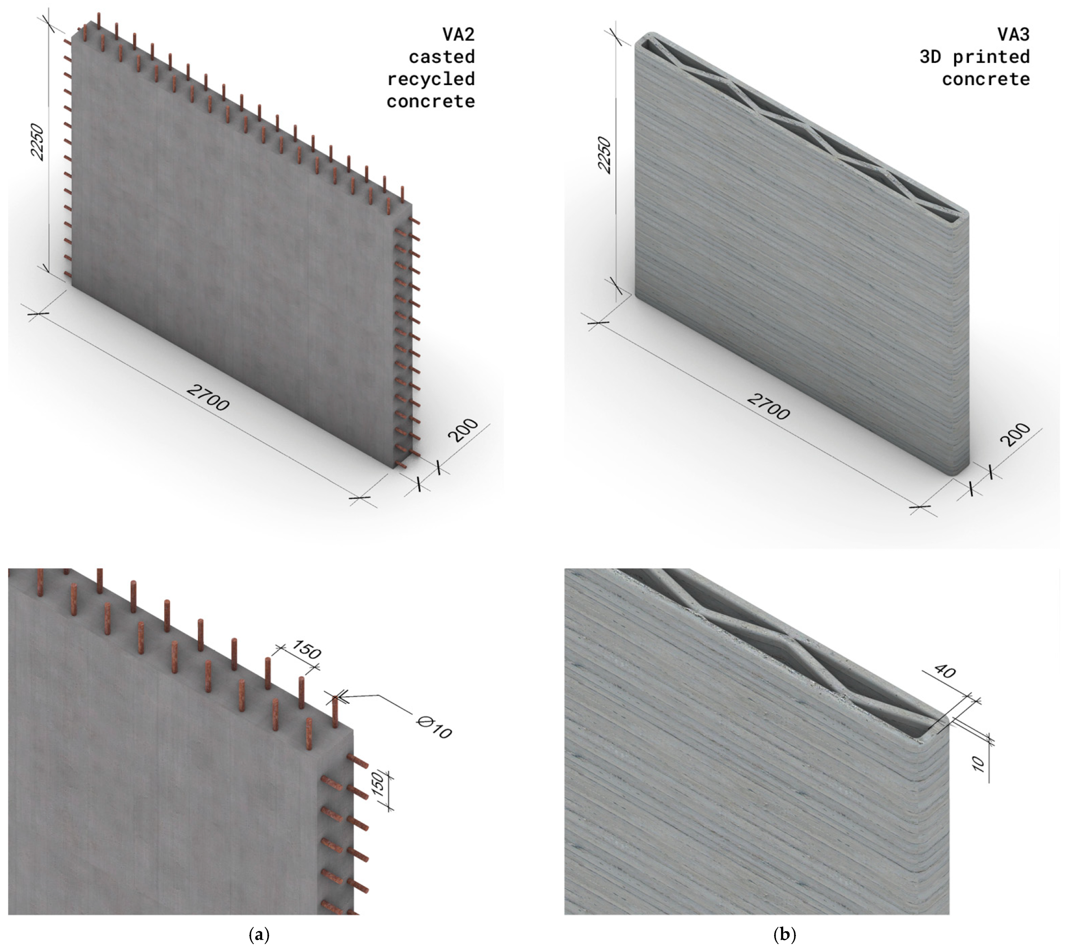
- a reinforced concrete structure with 50% of recycled aggregate (VA2);
- a 3D-printed hollow concrete structure (VA3) [63];
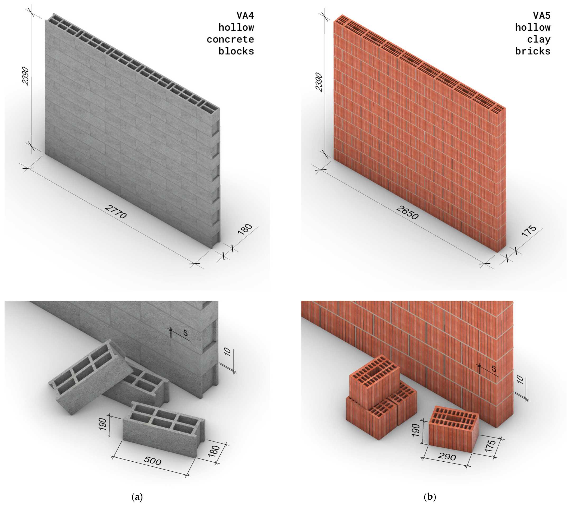
- a structure made of hollow concrete blocks and mortar (VA4);
- a structure made of hollow clay bricks and mortar (VA5).
4. Results
4.1. Demonstrator Design
4.2. Demonstrator Construction
4.3. Demonstrator Performances
4.3.1. Productivity
4.3.2. Construction Precision
4.3.3. Structural Performance
4.3.4. Energy Consumption
4.3.5. Environmental Impact
5. Discussion
5.1. Contributions
5.2. Limitations
5.2.1. Research Limitations
5.2.2. Industry Limitations
5.3. Future Works
6. Conclusions
Supplementary Materials
Author Contributions
Funding
Data Availability Statement
Acknowledgments
Conflicts of Interest
Appendix A. Wall Variants for the Life-Cycle Assessment
- Flat on both sides;
- Airtight;
- Freestanding without cross-wall connections;
- No openings;
- No slab nor floor connection;
- No additional building layers;
- Standard thickness;
- Load-bearing capacity of at least 2 MPa;
- Rectangular bounding geometry in elevation, of 6.05 m2, or as close as possible, with an aspect ratio (length/height) of 1.2, or as close as possible;
- On-site construction.
Appendix B. Data Used in the Life-Cycle Assessment

| Stage | Unit | kgCO2e/Unit | Source |
|---|---|---|---|
| Material production | |||
| Sandstone | kg | 0.149 | [69] |
| Masonry mortar | kg | 0.393 | [69] |
| Infill mortar | kg | 0.6436 | [89] |
| Fast setting mortar | kg | 0.6436 | assumption from [69,89] |
| Levelling mortar | kg | 0.341 | [90] |
| Crushed gravel | kg | 0.005 | [69] |
| Round gravel | kg | 0.003 | [69] |
| Sand | kg | 0.003 | [69] |
| Cement (CEM I, CAN B) | m3 | 249 | [91] |
| Aggregates (50% RCA) | m3 | 3 | [91] |
| Other for recycled concrete | m3 | 9 | [91] |
| Concrete with 50% RCA | m3 | 193 | [91] |
| Reinforcement steel | kg | 0.773 | [69] |
| Laminated board | kg | 0.942 | [69] |
| Construction process | |||
| Electricity | kWh | 0.125 | Swiss consumer mix [69] |
| Gasoil for machinery | kWh | 0.324 | [69] |
| Upcycling process | m3 | 0.722 | Calculated from demonstrator |
| Pumping | m3 | 1.00 | [92] |
| Robotic 3D printing | m2 | 46.12 | Unreinforced 20 cm thick [63] |
| Transport | |||
| Truck (7.5–16 t capacity) | tkm | 0.230 | [69] |
| End of life | |||
| Crushing (0–40 mm) | t | 1.733 | Calculated from industry data |
| Fines | kg | 0.013 | [69] |
| Unit | qte | |
|---|---|---|
| Height | m | 2.25 |
| Length | m | 2.70 |
| Width | m | 0.32 |
| Area | m2 | 6.075 |
| Bounding volume | m3 | 1.944 |
| Material | Unit | qte | Source |
|---|---|---|---|
| Sandstone | kg/m3 | 1400 | [69] |
| Fast setting mortar | kg/m3 | 2150 | [93] |
| Infill mortar | kg/m3 | 2250 | [94] |
| Levelling mortar | kg/m3 | 2100 | [95] |
| Gravel 8 mm | kg/m3 | 2000 | [95] |
| Concrete rubble | kg/m3 | 2336 | measured |
| Laminated board | kg/m3 | 823 | [95] |
| Rebar steel | kg/m3 | 7859 | [95] |
| Material | Unit | qte | Source | Comment |
|---|---|---|---|---|
| Infill mortar used | kg | 390 | measured | |
| Fast setting mortar used | kg | 100.5 | measured | |
| Levelling mortar used | kg | 80 | measured | |
| Total weight of wall | kg | 3493 | measured | |
| Large rubble (crane-placed) | kg | 2283 | measured | |
| Small rubble (manually placed) | kg | 1024 | assumed | |
| 8 mm gravel | kg | 165.3 | measured | To decrease mortar needs. Could be RCA |
| Name | Unit | qte | Source/Comment |
|---|---|---|---|
| Transport | |||
| Demolition site—Recycling centre | km | 30 | assumption |
| Demolition site—Construction site | km | 30 | assumption |
| Concrete plant—Construction site | km | 9 | |
| Recycling centre—Construction site | km | 3.1 | |
| Stone quarry—Construction site | km | 60 | |
| Brick and mortar supplier—Construction site | km | 4.7 | |
| Construction | |||
| Utilisation rate of available waste | % | 40 | |
| Assembly of robotic dry-stone masonry | kgCO2eq/m3 | 49.2 | [73] Incl. material |
| Reutilisation of formwork | x | 10 | |
| Rebar content | kg/m2 | 16.44 | comp. from ∅10, 150 mm |
| End of life | |||
| Concrete crushing consumption | litres/ton | 0.5 | Range is 0.25–0.5, technical doc + interview |
| Concrete hammering consumption | litters/ton | 0.5 | Range is 0.25–0.5 technical doc. +interviews |
| Oversized rubble pieces to be hammered | % | 4.8 | by weight, conservative |
| Yield of RCA production by crushing | % | 60 | [96] + interviews |
References
- Giorgi, S.; Lavagna, M.; Campioli, A. Guidelines for Effective and Sustainable Recycling of Construction and Demolition Waste. In Designing Sustainable Technologies, Products and Policies: From Science to Innovation; Benetto, E., Gericke, K., Guiton, M., Eds.; Springer International Publishing: Cham, Switzerland, 2018; pp. 211–221. ISBN 978-3-319-66981-6. [Google Scholar]
- Zhang, C.; Hu, M.; Di Maio, F.; Sprecher, B.; Yang, X.; Tukker, A. An Overview of the Waste Hierarchy Framework for Analyzing the Circularity in Construction and Demolition Waste Management in Europe. Sci. Total Environ. 2022, 803, 149892. [Google Scholar] [CrossRef] [PubMed]
- Scrivener, K.L.; John, V.M.; Gartner, E.M. Eco-Efficient Cements: Potential Economically Viable Solutions for a Low-CO2 Cement-Based Materials Industry. Cem. Concr. Res. 2018, 114, 2–26. [Google Scholar] [CrossRef]
- International Energy Agency. Material Efficiency in Clean Energy Transitions; OECD: Paris, France, 2019; ISBN 978-92-64-94131-1. [Google Scholar]
- Monteiro, P.J.M.; Miller, S.A.; Horvath, A. Towards Sustainable Concrete. Nat. Mater. 2017, 16, 698–699. [Google Scholar] [CrossRef]
- Knoeri, C.; Sanyé-Mengual, E.; Althaus, H.-J. Comparative LCA of Recycled and Conventional Concrete for Structural Applications. Int. J. Life Cycle Assess. 2013, 18, 909–918. [Google Scholar] [CrossRef]
- Küpfer, C.; Bastien-Masse, M.; Fivet, C. Reuse of Concrete Components in New Construction Projects: Critical Review of 77 Circular Precedents. J. Clean. Prod. 2023, 383, 135235. [Google Scholar] [CrossRef]
- Küpfer, C.; Bertola, N.; Fivet, C. Reuse of Cut Concrete Slabs in New Buildings for Circular Ultra-Low-Carbon Floor Designs. J. Clean. Prod. 2024, 448, 141566. [Google Scholar] [CrossRef]
- Abramson, D.M. Obsolescence: An Architectural History; The University of Chicago Press: Chicago, IL, USA, 2016; ISBN 978-0-226-31345-0. [Google Scholar]
- Abudayyeh, O.; Sawhney, A.; El-Bibany, H.; Buchanan, D. Concrete Bridge Demolition Methods and Equipment. J. Bridge Eng. 1998, 3, 117–125. [Google Scholar] [CrossRef]
- Diven, R.J.; Shaurette, M. Demolition: Practices, Technology, and Management; Purdue University Press: West Lafayette, IN, USA, 2010; ISBN 978-1-55753-567-2. [Google Scholar]
- Oyenuga, A.; Bhamidimarri, R. Upcycling Ideas for Sustainable Construction and Demolition Waste Management: Challenges, Opportunities, and Boundaries. Int. J. Innov. Res. Sci. Eng. Technol. 2017, 6, 1–14. [Google Scholar] [CrossRef]
- Facilitating the Circulation of Reclaimed Building Elements. Interreg Noth-West Europe Reuse Toolkit-Material Sheets-Concrete Rubble (Resulting from the Transformation of Concrete Construction Elements); Facilitating the Circulation of Reclaimed Building Elements: Brussels, Belgium, 2021. [Google Scholar]
- Noël, M. Le Camp Américain de Mesves-Bulcy. Wiki58 2020. Available online: https://www.gennievre.net/wiki/index.php?title=Le_camp_am%C3%A9ricain_de_Mesves-Bulcy (accessed on 12 December 2024).
- Collaud, A.; Mongillo, M.; Niederhäuser, E.L.; Pathé, J.; Redaelli, D.; Buri, H. Reuse of Concrete for the Construction of a Retaining Wall: A Case Study. J. Phys. Conf. Ser. 2023, 2600, 192016. [Google Scholar] [CrossRef]
- Mainland Aggregates Ltd. Recycled Gabion Fill. Available online: https://web.archive.org/web/20150904025627/https://www.mainlandaggregates.co.uk/recycled-gabion-fill.html (accessed on 7 February 2024).
- AbuHamed, H.; Al Bursh, W.; Abu Mfarreh, S.; Yoshida, M. Managing Post-Conflict Demolition Wastes in Gaza Strip: A Case Study on May 2021 Conflict. J. Mater. Cycles Waste Manag. 2023, 25, 684–693. [Google Scholar] [CrossRef]
- Oreb, J.; Curić, H.; Tomić, I.; Beyer, K. Masonry Walls from Reclaimed Concrete Demolition Waste. Matec Web Conf. 2024, 403, 06004. [Google Scholar] [CrossRef]
- Clifford, B.; McGee, W.; Muhonen, M. Recovering Cannibalism in Architecture with a Return to Cyclopean Masonry. Nexus Netw. J. 2018, 20, 583–604. [Google Scholar] [CrossRef]
- Clifford, B. The Cannibal’s Cookbook: Mining Myths of Cyclopean Constructions, 2nd ed.; Oro Editions: Novato, CA, USA, 2021; ISBN 978-1-951541-43-9. [Google Scholar]
- Marshall, D.; Mueller, C.; Clifford, B.; Kennedy, S. Computational Arrangement of Demolition Debris. Detritus 2020, 11, 3–18. [Google Scholar] [CrossRef]
- Marshall, D.; Grangeot, M. An Investigation into Machine Learning Matchmaking for Reused Rubble Concrete Masonry Units (RR-CMU). In Proceedings of the Redefining the Art of Structural Design, Zurich, Switzerland, 26–30 August 2024; Block, P., Boller, G., De Wolf, C., Pauli, J., Kaufmann, W., Eds.; IASS: Zurich, Switzerland, 2024. [Google Scholar]
- Furrer, F.; Wermelinger, M.; Yoshida, H.; Gramazio, F.; Kohler, M.; Siegwart, R.; Hutter, M. Autonomous Robotic Stone Stacking with Online next Best Object Target Pose Planning. In Proceedings of the 2017 IEEE International Conference on Robotics and Automation (ICRA), Singapore, 29 May–3 June 2017; pp. 2350–2356. [Google Scholar]
- Rickhoff, S. Rubble Aggregations. In The Robotic Touch: How Robots Change Architecture; Gramazio, F., Kohler, M., Willmann, J., Eds.; Park Books: Zurich, Switzerland, 2014; ISBN 978-3-906027-37-1. [Google Scholar]
- Grangeot, M.; Fivet, C.; Parascho, S. From Concrete Waste to Walls: An Investigation of Reclamation and Digital Technologies for New Load-Bearing Structures. J. Phys. Conf. Ser. 2023, 2600, 192019. [Google Scholar] [CrossRef]
- Li, Y.; Mei, Y.; Yan, X.; Wang, S.; Fingrut, A. Digital Framework for Generative Design of Reused Concrete Structure Rubbles. In Proceedings of the Architectural Informatics, Tokyo, Japan, 22–29 March 2025. [Google Scholar]
- Marshall, D.J.M. Unmaking Architecture: Holding Patterns for Misfit Matter. Master’s Thesis, Massachusetts Institute of Technology, Cambridge, MA, USA, 2019. [Google Scholar]
- Gaudillière-Jami, N.; Eschenbach, M.B.; Tessmann, O. Printsugi: Matter as Met, Matter as Printed. In Leveraging Computational Design Tools for a More Virtuous Material Extraction and End-of-Life, Proceedings of the Design for Rethinking Resources, Copenhagen, Denmark, 2–6 July 2023; Thomsen, M.R., Ratti, C., Tamke, M., Eds.; Springer International Publishing: Cham, Switzerland, 2024; pp. 423–435. [Google Scholar]
- Architektur, F. Design with Debris. Available online: https://www.architektur.tu-darmstadt.de/forschen/forschungsprojekte/forschungsprojekte_arch/standardseite_10.de.jsp (accessed on 17 March 2024).
- Al Khayat, L.K.Y. Fibers and Fragments-Weaving Local Resources into the Arabian Gulf’s Modern Material Culture. Master’s Thesis, Massachusetts Institute of Technology, Cambridge, MA, USA, 2023. [Google Scholar]
- Siefert, S. Beyond Debris, A. Computational Framework for Demolition Debris Reuse; Royal Danish Academy: Copenhagen, Denmark, 2024. [Google Scholar]
- Henning, S. Concrete Lines of Flight; Royal Danish Academy: Copenhagen, Denmark, 2024. [Google Scholar]
- Blödel, C. Rubble Probes—Soft Rubble as Building Process–Studio Charly Blödel; Design Academy: Eindhoven, The Netherlands, 2020. [Google Scholar]
- Grangeot, M.; Parascho, S.; Fivet, C. Concrete Rubble as a New Construction Material: Panorama of Applications to Known Structural Typologies. In Proceedings of the Redefining the Art of Structural Design, Zurich, Switzerland, 26–30 August 2024; Block, P., Boller, G., De Wolf, C., Pauli, J., Kaufmann, W., Eds.; IASS: Zurich, Switzerland, 2024. [Google Scholar]
- Wyller, M.; Svatoš-Ražnjević, H.; Schad, E.; Menges, A. A Taxonomy of Techniques and Tools for Rubble. In Proceedings of the Scalable Disruptors, Kassel, Germany, 16–18 September 2024; Eversmann, P., Gengnagel, C., Lienhard, J., Ramsgaard Thomsen, M., Wurm, J., Eds.; Springer Nature: Cham, Switzerland, 2024; pp. 3–14. [Google Scholar]
- Johns, R.L.; Wermelinger, M.; Mascaro, R.; Jud, D.; Hurkxkens, I.; Vasey, L.; Chli, M.; Gramazio, F.; Kohler, M.; Hutter, M. A Framework for Robotic Excavation and Dry Stone Construction Using On-Site Materials. Sci. Robot. 2023, 8, eabp9758. [Google Scholar] [CrossRef]
- Jud, D.; Kerscher, S.; Wermelinger, M.; Jelavic, E.; Egli, P.; Leemann, P.; Hottiger, G.; Hutter, M. HEAP-The Autonomous Walking Excavator. Autom. Constr. 2021, 129, 103783. [Google Scholar] [CrossRef]
- Schweizerischer Ingenieur-und Architektenverein Norm SIA 266/2-Natural stone masonry; 2012. Available online: https://shop.sia.ch/177d033e-3916-4208-b26e-e62881ab7b20/D/DownloadAnhang (accessed on 1 April 2025).
- Muttoni, A. The Art of Structures: Introduction to the Functioning of Structures in Architecture; EPFL Press: Lausanne, Switzerland, 2011; ISBN 978-2-940222-38-4. [Google Scholar]
- Engel, H. Tragsysteme; Gerd Hatje: Ostfildern Ruit, Germany, 1999; ISBN 978-3-7757-0706-0. [Google Scholar]
- Wibranek, B.; Tessmann, O. Digital Rubble Compression-Only Structures with Irregular Rock and 3D Printed Connectors. In Proceedings of the Advanced Manufacturing and Non-conventional Materials, International Association for Shell and Spatial Structures (IASS), Barcelona, Spain, 7 October 2019; Volume 8, pp. 1–8. [Google Scholar]
- Perraudin, G. Constructing in Massive Stone Today; Les Presses du Réel: Dijon, France, 2013; ISBN 978-2-84066-680-6. [Google Scholar]
- Reuse in Construction: A Compendium of Circular Architecture; Stricker, E., Brandi, G., Sonderegger, A., Angst, M., Buser, B., Massmünster, M., Eds.; Park Books: Zurich, Switzerland, 2022; ISBN 978-3-03860-295-8. [Google Scholar]
- Gargiani, R. Treatise on concrete. In A New Era of American Architectural Concrete: From Wright to Som; EPFL Press: Lausanne, Switzerland, 2020; ISBN 978-2-88915-402-9. [Google Scholar]
- Adam, J.-P. Roman Building: Materials and Techniques; Routledge: London, UK, 2005; ISBN 978-1-134-61870-5. [Google Scholar]
- Dry Stone Walls: Fundamentals, Construction Guidelines, Significance; Swiss Environmental Action Foundation, Ed.; Scheidegger & Spiess: Zurich, Switzerland, 2019; ISBN 978-3-85881-813-3. [Google Scholar]
- Settimi, A.; Wang, Q.; Andò, E.; Gamerro, J.; Beyer, K.; Weinand, Y. Projector-Based Augmented Stacking Framework for Irregularly Shaped Objects. Constr. Robot. 2023, 7, 159–175. [Google Scholar] [CrossRef]
- Liu, Y.; Shamsi, S.M.; Fang, L.; Chen, C.; Napp, N. Deep Q-Learning for Dry Stacking Irregular Objects. In Proceedings of the 2018 IEEE/RSJ International Conference on Intelligent Robots and Systems (IROS), Madrid, Spain, 1–5 October 2018; pp. 1569–1576. [Google Scholar]
- Menezes, A.; Vicente, P.; Bernardino, A.; Ventura, R. From Rocks to Walls: A Model-Free Reinforcement Learning Approach to Dry Stacking with Irregular Rocks. In Proceedings of the 2021 IEEE/CVF Conference on Computer Vision and Pattern Recognition Workshops (CVPRW), IEEE, Nashville, TN, USA, 19–25 June 2021; pp. 2057–2065. [Google Scholar]
- Wermelinger, M.; Johns, R.; Gramazio, F.; Kohler, M.; Hutter, M. Grasping and Object Reorientation for Autonomous Construction of Stone Structures. IEEE Robot. Autom. Lett. 2021, 6, 5105–5112. [Google Scholar] [CrossRef]
- Kasirer, C.; Casas, G.; Pok Yin Leung, V. OpenCV-Based 2D Tile Detector 2023. Available online: https://zenodo.org/record/7712950 (accessed on 9 March 2023).
- Bradski, G. The OpenCV Library. Dr. Dobb’s J. Softw. Tools 2000, 25, 120–123. [Google Scholar]
- Wang, Q.; Pantoja-Rosero, B.G.; dos Santos, K.R.M.; Beyer, K. An Image Convolution-Based Method for the Irregular Stone Packing Problem in Masonry Wall Construction. Eur. J. Oper. Res. 2024, 316, 733–753. [Google Scholar] [CrossRef]
- Lambert, M.; Kennedy, P. Using Artificial Intelligence to Build with Unprocessed Rock. Key Eng. Mater. 2012, 517, 939–945. [Google Scholar] [CrossRef]
- Thangavelu, V.; Liu, Y.; Saboia, M.; Napp, N. Dry Stacking for Automated Construction with Irregular Objects. In Proceedings of the 2018 IEEE International Conference on Robotics and Automation (ICRA), Brisbane, Australia, 21–25 May 2018; pp. 4782–4789. [Google Scholar]
- Grangeot, M.; Wang, Q.; Beyer, K.; Fivet, C.; Parascho, S. Structural Concrete Rubble Arrangements: A Framework for Upcycling Demolition Waste into Slender Masonry Walls for Building. In Proceedings of the Scalable Disruptors, Kassel, Germany, 16–18 September 2024; Springer: Cham, Switzerland, 2024; pp. 15–27. [Google Scholar]
- Almeida, C.; Guedes, J.P.; Arêde, A.; Costa, A. Geometric Indices to Quantify Textures Irregularity of Stone Masonry Walls. Constr. Build. Mater. 2016, 111, 199–208. [Google Scholar] [CrossRef]
- Almeida, C.; Miranda Guedes, J.; Arêde, A.; Costa, A. Compressive Behaviour of Old One-Leaf Stone Masonry Walls; the Influence of Patterns’ Regularity and Constructive Process. Constr. Build. Mater. 2021, 311, 125339. [Google Scholar] [CrossRef]
- Belin, P.; Habert, G.; Thiery, M.; Roussel, N. Cement Paste Content and Water Absorption of Recycled Concrete Coarse Aggregates. Mater. Struct. 2014, 47, 1451–1465. [Google Scholar] [CrossRef]
- Société Suisse des Ingénieurs et des Architectes. SIA 262-Concrete Structures; Société Suisse des Ingénieurs et des Architectes: Zurich, Switzerland, 2013. [Google Scholar]
- SIA 262/1; Schweizerischer Ingenieur-und Architektenverein Norm, Concrete Structures–Supplementary Specifications. SIACH: Zurich, Switzerland, 2019.
- Gehri, N.; Mata-Falcón, J.; Kaufmann, W. Automated Crack Detection and Measurement Based on Digital Image Correlation. Constr. Build. Mater. 2020, 256, 119383. [Google Scholar] [CrossRef]
- Mohammad, M.; Masad, E.; Al-Ghamdi, S.G. 3D Concrete Printing Sustainability: A Comparative Life Cycle Assessment of Four Construction Method Scenarios. Buildings 2020, 10, 245. [Google Scholar] [CrossRef]
- ISO14044; 2006-Environmental Management–Life Cycle Assessment–Requirements and Guidelines. International Organization for Standardization: Geneva, Switzerland, 2006.
- ISO14040; Environmental Management–Life Cycle Assessment–Principles and Framework. International Organization for Standardization: Geneva, Switzerland, 2006.
- Methodological Fundamentals and Their Application in Switzerland. Swiss Eco-Factors 2021 According to the Ecological Scarcity Method; Federal Office for the Environment, Ed.; Federal Office for the Environment: Bern, Switzerland, 2021; Volume Connaissance de l’environnement. [Google Scholar]
- EN 15978:2011; Sustainability of Construction Works—Assessment of Environmental Performance of Buildings—Calculation Method. European Committee for Standardization (CEN): Brussels, Belgium, 2011.
- Schrijvers, D.L.; Loubet, P.; Sonnemann, G. Developing a Systematic Framework for Consistent Allocation in LCA. Int. J. Life Cycle Assess 2016, 21, 976–993. [Google Scholar] [CrossRef]
- KBOB; Eco-Bau. IPB Données des Écobilans dans la Construction 2009/1:2022. Available online: https://www.kbob.admin.ch/kbob/fr/home.html (accessed on 25 March 2024).
- EN 15804+A2; Sustainability of Construction Works-Environmental Product Declarations-Core Rules for the Product Category of Construction Products. European Committee for Standardization (CEN): Brussels, Belgium, 2019.
- Agustí-Juan, I.; Müller, F.; Hack, N.; Wangler, T.; Habert, G. Potential Benefits of Digital Fabrication for Complex Structures: Environmental Assessment of a Robotically Fabricated Concrete Wall. J. Clean. Prod. 2017, 154, 330–340. [Google Scholar] [CrossRef]
- Saloustros, S.; Settimi, A.; Ascencio, A.C.; Gamerro, J.; Weinand, Y.; Beyer, K. Geometrical Digital Twins of the As-Built Microstructure of Three-Leaf Stone Masonry Walls with Laser Scanning. Sci. Data 2023, 10, 533. [Google Scholar] [CrossRef]
- Johns, R.L. Autonomous Dry Stone: Mobile Robotic Construction with Naturally Nonstandard Materials. Ph.D. Thesis, ETH Zurich, Zurich, Switzerland, 2023. [Google Scholar]
- García de Soto, B.; Agustí-Juan, I.; Hunhevicz, J.; Joss, S.; Graser, K.; Habert, G.; Adey, B.T. Productivity of Digital Fabrication in Construction: Cost and Time Analysis of a Robotically Built Wall. Autom. Constr. 2018, 92, 297–311. [Google Scholar] [CrossRef]
- Bos, F.; Wolfs, R.; Ahmed, Z.; Salet, T. Additive Manufacturing of Concrete in Construction: Potentials and Challenges of 3D Concrete Printing. Virtual Phys. Prototyp. 2016, 11, 209–225. [Google Scholar] [CrossRef]
- RSMeans Engineering Staff RSMeans Building Construction Cost Data; RSMeans: Greenville, CA, USA, 2014.
- Almeida, C.; Guedes, J.; Arêde, A.; Costa, A. Experimental Study on the Compressive Cyclic Behaviour of One-Leaf Stone Masonry Walls with Different Regularity Patterns. In Proceedings of the 9th International Masonry Conference 2014, Guimarães, Portugal, 1 January 2014. [Google Scholar]
- Almeida, C.; Costa, C.; Guedes, J.; Arêde, A.; Costa, A.; Costa, A. The Influence of Material Characteristics on the Mechanical Behaviour of Stone Masonry Walls. In Proceedings of the 8th International Masonry Conference, Dresden, Germany, 1 January 2010; pp. 683–692. [Google Scholar]
- Eckert, M.; Oliveira, M. Mitigation of the Negative Effects of Recycled Aggregate Water Absorption in Concrete Technology. Constr. Build. Mater. 2017, 133, 416–424. [Google Scholar] [CrossRef]
- Almeida, C.; Guedes, J.P.; Arêde, A.; Costa, C.Q.; Costa, A. Physical Characterization and Compression Tests of One Leaf Stone Masonry Walls. Constr. Build. Mater. 2012, 30, 188–197. [Google Scholar] [CrossRef]
- SIA 177.181; Schweizerischer Ingenieur-und Architektenverein Norme, Méthodes d’essai de la maçonnerie-Partie 1: Détermina-tion de la résistance à la compression. Schweizerischer Ingenieur-und Architektenverein: Zürich, Switzerland, 1999.
- SIA 260; Schweizerischer Ingenieur-und Architektenverein Norm, Basis of Structural Design. Schweizerischer Ingenieur-und Architektenverein: Zürich, Switzerland, 2013.
- ICON-Vulcan 3D Printer Technical Specs. Available online: https://iconbuild.com/faq?tab=our-technology&question=what-are-the-technical-specs-of-the-latest-vulcan-construction-system (accessed on 25 September 2024).
- Loughran, P. Failed Stone: Problems and Solutions with Concrete and Masonry; Birkhäuser: Basel, Switzerland, 2007; ISBN 978-3-7643-7329-0. [Google Scholar]
- COBOD BOD2 3D Construction Printer-Technical Specifications; 2021. Available online: https://cobod.com/wp-content/uploads/2022/06/eu-cobod-bod2-techspecs.pdf (accessed on 21 April 2024).
- HGC Catalog of Construction Materials and Tools; HGC: Zurich, Switzerland 2022. Available online: https://oxomi.com/p/3001322/catalog/10391611 (accessed on 21 April 2024).
- Deplazes, A. Constructing Architecture: Materials, Processes, Structures, a Handbook.; Birkhäuser-Publishers for Architecture: Basel, Switzerland, 2005; ISBN 978-3-7643-7190-6. [Google Scholar]
- SIA 266; Schweizerischer Ingenieur-und Architektenverein Norme, Construction en maçonnerie. Schweizerischer Ingenieur-und Architektenverein: Zürich, Switzerland, 2012.
- Sika Declaration of Conformity with Model EPD SikaGrout®-800; Sika: Zurich, Switzerland 2022. Available online: https://esp.sika.com/dam/dms/es01/6/EPD-IBU-SikaGrout-800-ES_en-GB.pdf (accessed on 19 April 2024).
- BRE Global Ltd. Environmental Product Declaration Sika MonoTop®-4012; Sika: Zurich, Switzerland, 2022. [Google Scholar]
- Conférence de Coordination des Services de la Construction et des Immeubles des Maîtres D’ouvrage Publics KBOB Betonsortenrechner Planer:Innen. Available online: https://rechner.umweltchemie.ch/HTMLBetonsorten22d_v6/Oekobilanzrechner_Betonsorten_Planende_2022_deutsch_v6_UVEK2022.htm (accessed on 6 December 2023).
- Oekobaudat Process Data Set: Pumping of Concrete; 2022. Available online: https://www.oekobaudat.de/OEKOBAU.DAT/datasetdetail/process.xhtml?uuid=fdcb26f9-1f0c-4766-ad94-c093e5d259e1&version=20.19.120 (accessed on 17 April 2024).
- Sika Product data sheet-Sika® FastFix-121; Sika: Zurich, Switzerland 2020. Available online: https://che.sika.com/dam/dms/ch01/o/sika_fastfix-121.pdf (accessed on 19 April 2024).
- Sika Product data sheet-SikaGrout®-800; Sika: Zurich, Switzerland. 2024. Available online: https://che.sika.com/dam/dms/ch01/p/sikagrout-800.pdf (accessed on 19 April 2024).
- Sika Product Data Sheet-Sika MonoTop®-4012; Sika: Zurich, Switzerland. 2024. Available online: https://gbr.sika.com/content/dam/dms/gb01/b/sika-monotop-4012.pdf (accessed on 19 April 2024).
- Nežerka, V.; Prošek, Z.; Trejbal, J.; Pešta, J.; Ferriz-Papi, J.A.; Tesárek, P. Recycling of Fines from Waste Concrete: Development of Lightweight Masonry Blocks and Assessment of Their Environmental Benefits. J. Clean. Prod. 2023, 385, 135711. [Google Scholar] [CrossRef]


| Safe | Scalable | Resilient | Rapid | Precise | |
|---|---|---|---|---|---|
| Dry fit/wedges | x | xxx | x | xxx | xxx |
| 3D-printed connectors [41] | x | x | x | xx | xxx |
| Pouring flat connections | xx | xxx | xx | x | xx |
| Mesh/Jamming | x | xxx | xxx | xxx | xx |
| Dowels | xx | xx | xx | xx | xxx |
| Tie | xxx | x | x | xx | xxx |
| Climbing formwork | x | xx | xxx | xx | xx |
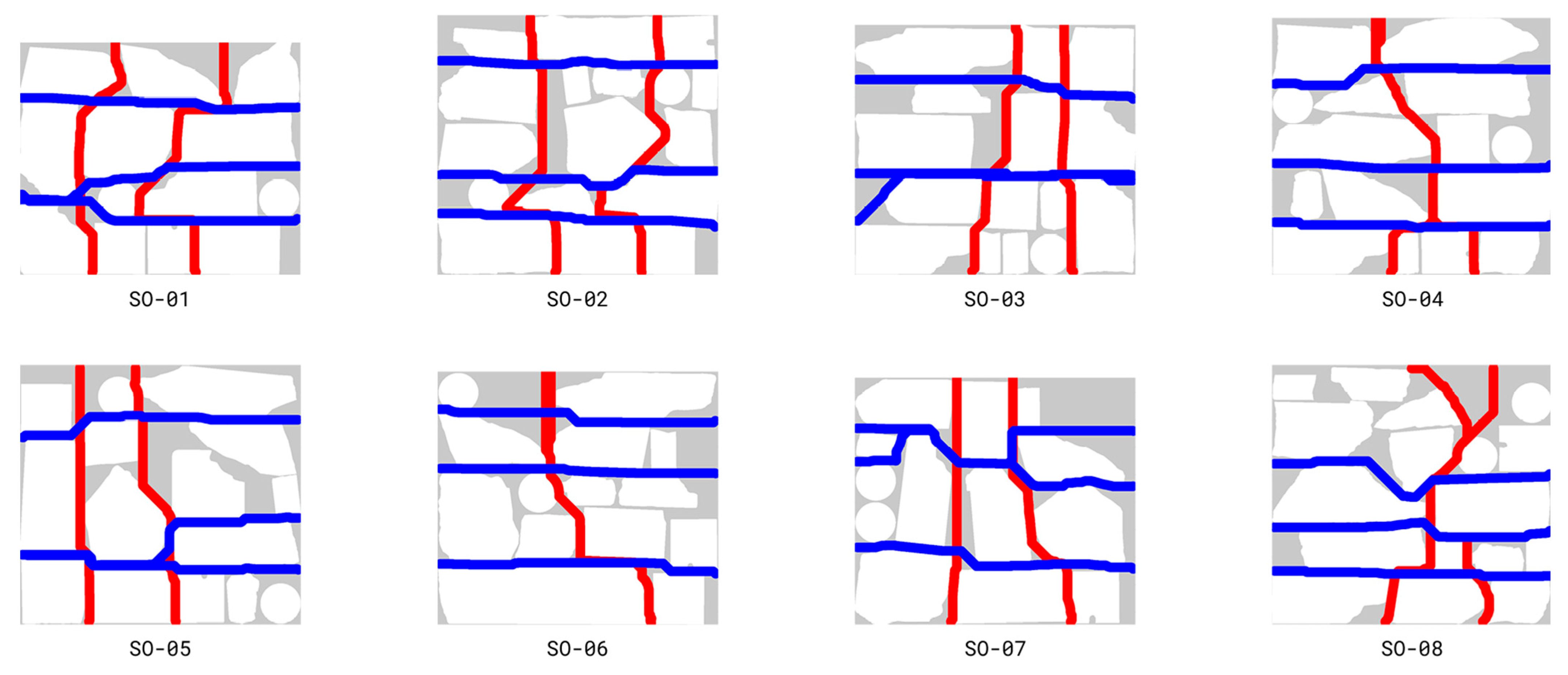
| Solution | Void Area [%] | FFP [%] | FAH [%] | FAV [%] |
|---|---|---|---|---|
| SO-1 | 22.35 | 7.97 | 3.94 | 28.53 |
| SO-2 | 24.80 | 7.36 | 2.83 | 28.38 |
| SO-3 | 24.88 | 7.32 | 4.39 | 5.12 |
| SO-4 | 25.20 | 9.19 | 1.94 | 24.19 |
| SO-5 | 25.46 | 8.18 | 7.41 | 4.59 |
| SO-6 | 25.52 | 7.22 | 1.67 | 29.10 |
| SO-7 | 26.61 | 8.22 | 14.11 | 6.58 |
| SO-8 | 26.71 | 9.25 | 4.65 | 30.09 |
| Ratio of Mortar [vol%] | |
|---|---|
| Almeida et al. [57] 1 | 13–23 |
| Norms [38] 2 | 15–24 |
| Saloustros et al. [72] | 42 |
| Oreb et al. [18] | 29–46 |
| Historical renovation 3 | 34–38 |
| Grangeot et al. (this study) | 19 |
| Unit Weight (Average) [kg] | Productivity [m2/h] | Density [unit/m3] | |
|---|---|---|---|
| Robotic retaining wall 1 [73] | 997 | 1.23 | 1.6 |
| Excavator boulder wall [73] | - | 1.82 | - |
| Robotic mesh mould wall [74] | - | 0.10 | - |
| Concrete 3D printing 4 [75] | - | 1.194 | - |
| Dry stone masonry [76] | 5–15 6 | 0.33 | 100–300 6 |
| Irregular stone masonry 2 [76] | 5–15 6 | 0.28 | 100–300 6 |
| Concrete casting 3 [76] | - | 0.46 | - |
| Concrete Block Masonry 5 [76] | 20 | 0.98 | 55 |
| Clay Brick Masonry 5 [76] | 8 | 0.57 | 97 |
| Small concrete rubble wall [18] | 2–11 6 | 0.04.-0.08 | 150–700 |
| Large concrete rubble wall (this study) | 163 | 0.15 | 7.3 |
| Energy Demand [kWh/m2] | |
|---|---|
| Robotic boulder wall 1 [73] | 72–110 |
| Engineered boulder wall 2 | 49–75 |
| Robotic mesh wall [74] | 17 |
| 3D-printed concrete wall [83] | 1.87 |
| Manual stone masonry 3 | 0.17 |
| Large concrete rubble wall (this study) | 1.83 |
Disclaimer/Publisher’s Note: The statements, opinions and data contained in all publications are solely those of the individual author(s) and contributor(s) and not of MDPI and/or the editor(s). MDPI and/or the editor(s) disclaim responsibility for any injury to people or property resulting from any ideas, methods, instructions or products referred to in the content. |
© 2025 by the authors. Licensee MDPI, Basel, Switzerland. This article is an open access article distributed under the terms and conditions of the Creative Commons Attribution (CC BY) license (https://creativecommons.org/licenses/by/4.0/).
Share and Cite
Grangeot, M.; Bastien-Masse, M.; Fivet, C.; Parascho, S. Large Concrete Rubble as a New Structural Construction Material: Opportunities and Digital Processes for Load-Bearing Walls. Buildings 2025, 15, 1437. https://doi.org/10.3390/buildings15091437
Grangeot M, Bastien-Masse M, Fivet C, Parascho S. Large Concrete Rubble as a New Structural Construction Material: Opportunities and Digital Processes for Load-Bearing Walls. Buildings. 2025; 15(9):1437. https://doi.org/10.3390/buildings15091437
Chicago/Turabian StyleGrangeot, Maxence, Malena Bastien-Masse, Corentin Fivet, and Stefana Parascho. 2025. "Large Concrete Rubble as a New Structural Construction Material: Opportunities and Digital Processes for Load-Bearing Walls" Buildings 15, no. 9: 1437. https://doi.org/10.3390/buildings15091437
APA StyleGrangeot, M., Bastien-Masse, M., Fivet, C., & Parascho, S. (2025). Large Concrete Rubble as a New Structural Construction Material: Opportunities and Digital Processes for Load-Bearing Walls. Buildings, 15(9), 1437. https://doi.org/10.3390/buildings15091437