


Quasi-Static Testing of Unreinforced Masonry Walls Using Different Styles of Basalt Fiber Mortar Surface Reinforcements

Abstract
1. Introduction

| Researcher | Fiber Type | Fiber Content | Cracking Load | Peak Load | Ductility | Others |
|---|---|---|---|---|---|---|
| Zhou TG [25] | PVA fiber | 2% | +133.3% | +4.5% | +27.0% | Energy dissipation +133.3% |
| Deng MK [26] | PVA fiber | 2% | +20% | +25.5% | +44.2% | / |
| Wang ZL [27] | PVA fiber | 2% | +0.8% | +88.8% | / | / |
| Zhang W [28] | PVA fiber | 1.7% | +4.5% | +26.9% | / | Energy dissipation +343% |
| Facconi, L [29] | High-carbon steel fiber | 0.82% | / | +39% | / | From diagonal shear failure to rocking failure |
| Stainless-steel fiber | 0.82% | / | +49% | / | ||
| Liu GA [30] | Steel fiber PP fiber | 1.5% 0.5% | +49% | +85% | / | Initial stiffness +57.9% Energy dissipation +171.8% |
| Arslan, ME [31] | Basalt fiber | 1% | / | +155.1% | +43.6% | Initial stiffness +42.6% |
| 2% | / | +172.9% | +42.4% | +74.8%, | ||
| 3% | / | +108.1% | +42.4% | +129.5%, | ||
| Glass fiber | 1% | / | +175.9% | +63.6% | +60.3%, | |
| 2% | / | +181.4% | +75.8% | +74.8%, | ||
| 3% | / | +144.9% | +81.8% | +9.4%, | ||
| Du YF [32] | PP fiber | / | +30.8% | −12.5% | / | / |
2. Materials
2.1. Basalt Fiber
2.2. Basalt Fiber Mesh
2.3. Masonry Brick
2.4. Mortar
3. Test Process
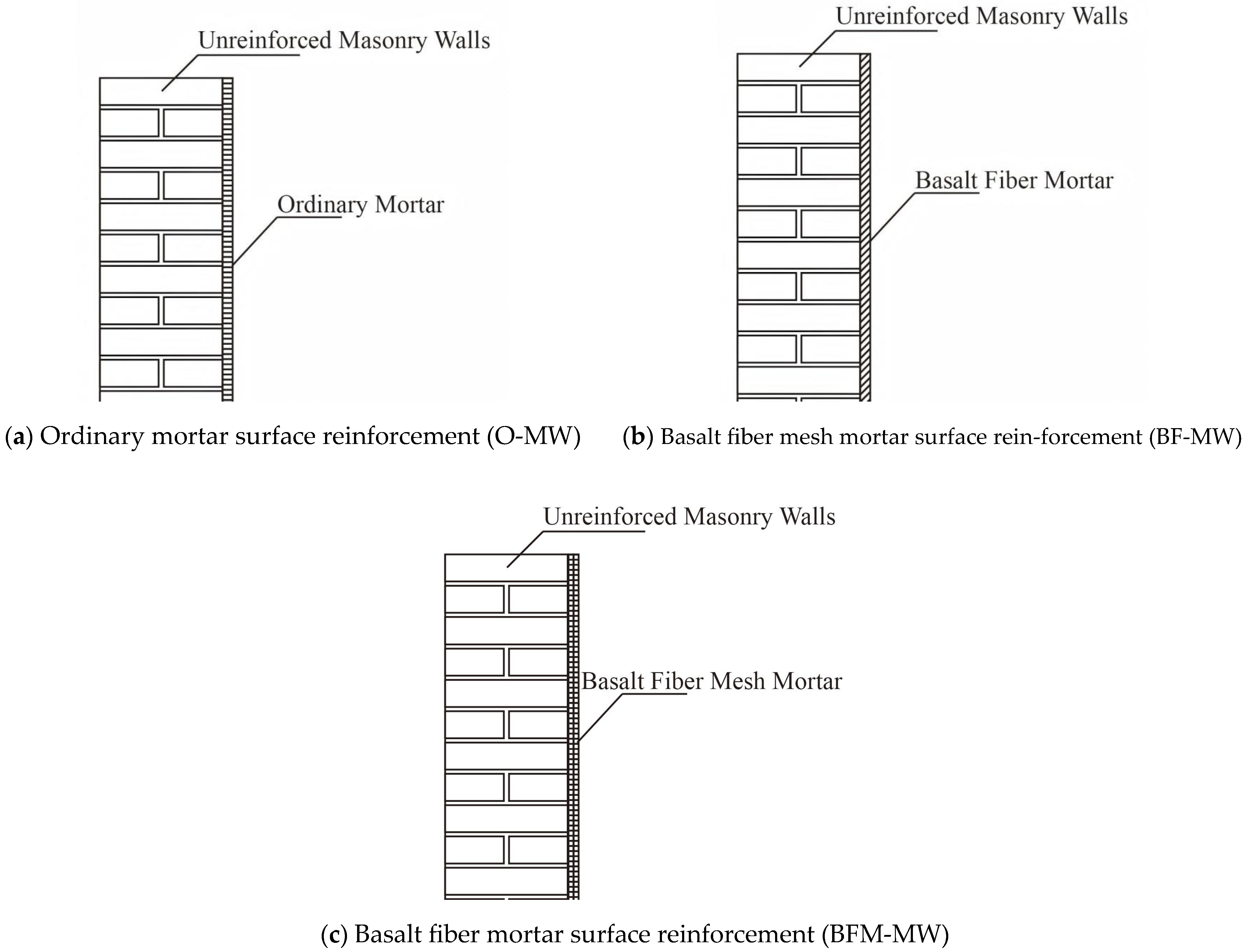
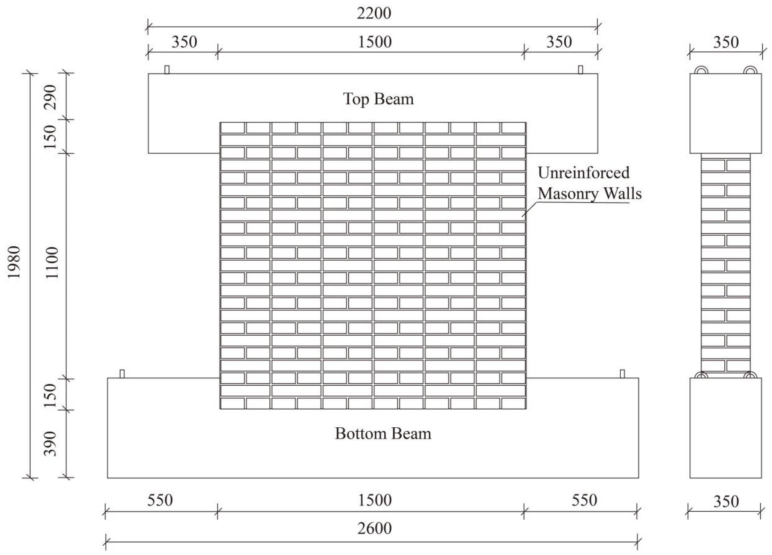
3.1. Specimen Preparation
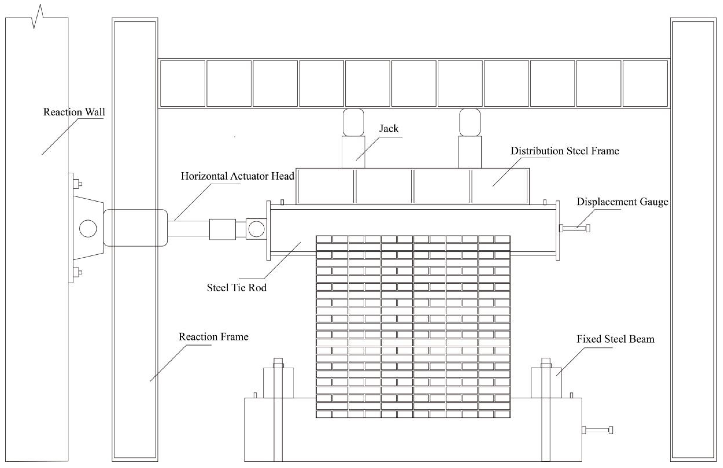
3.2. Tester
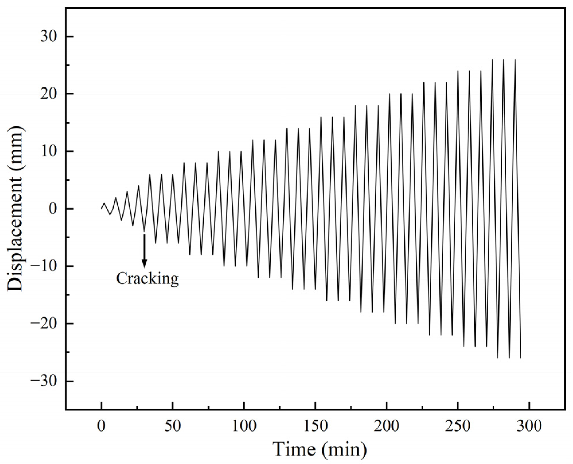
3.3. Loading System
4. Results and Discussion
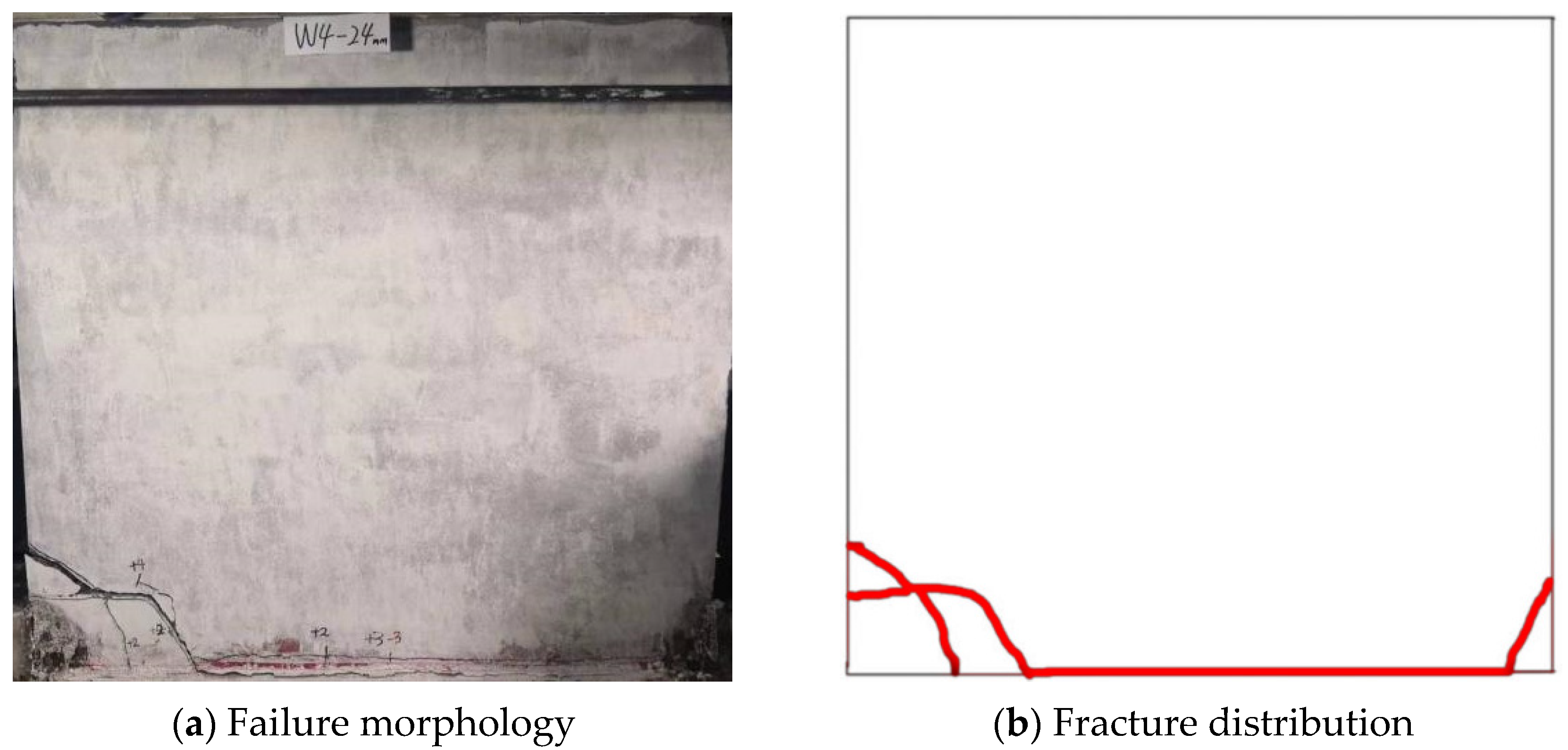
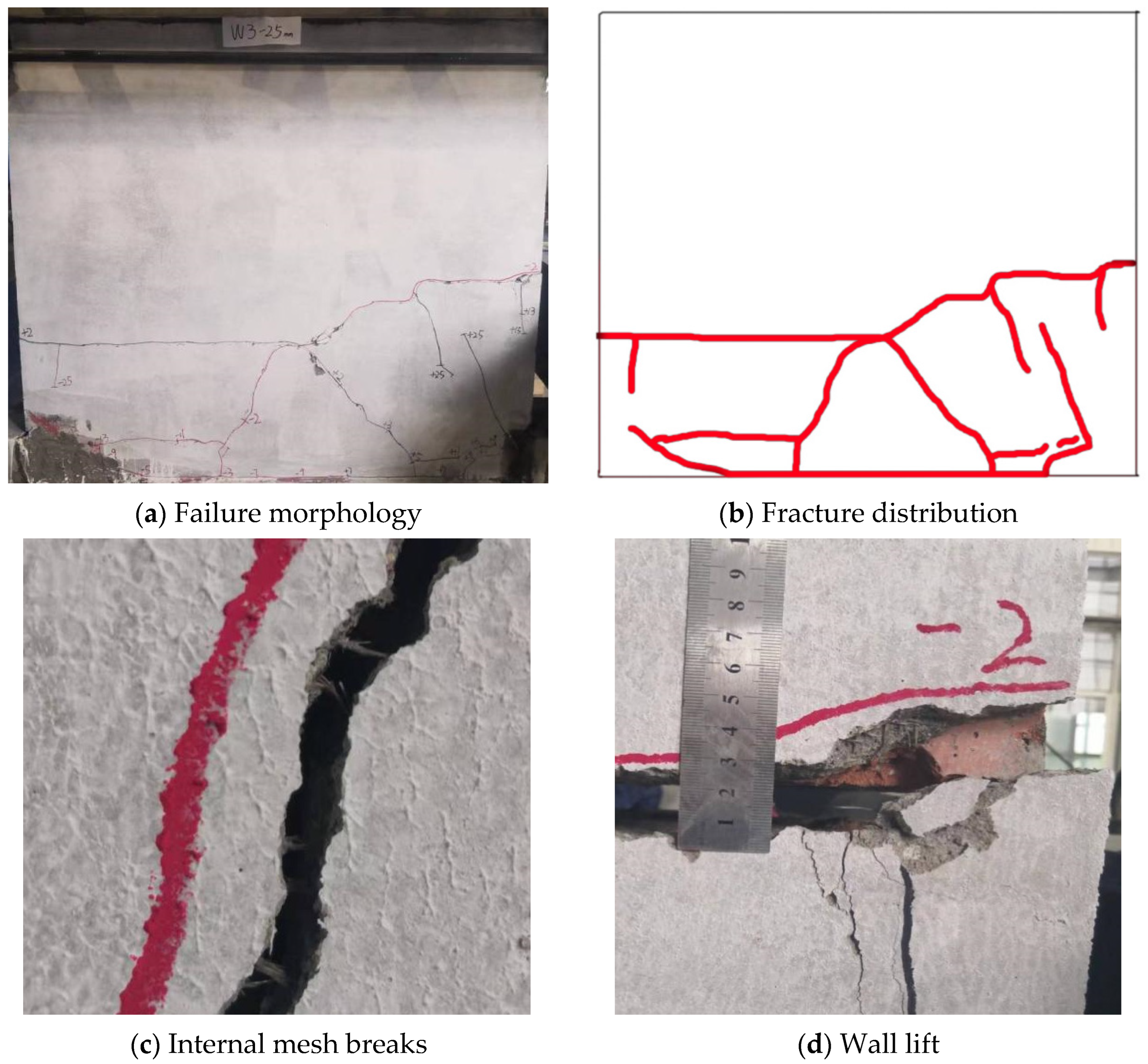
4.1. Failure Phenomena
4.2. Load-Bearing Characteristics and Cyclic Response Analysis
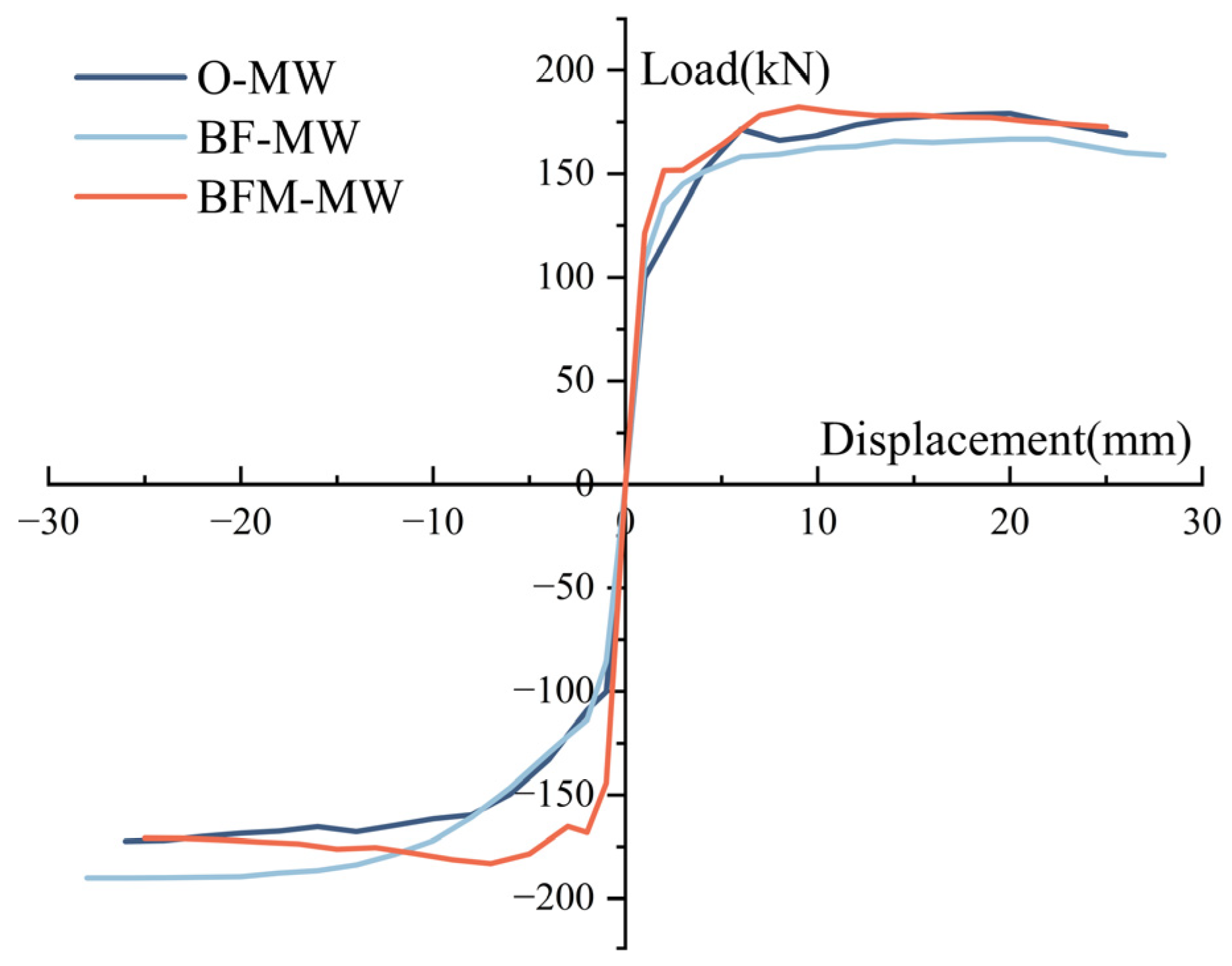
4.2.1. Feature Bearing Capacity
- (1)
- The application of basalt fiber mesh mortar or basalt fiber mortar led to an increase in both the cracking load and peak load of masonry walls compared to those reinforced with ordinary mortar. Specifically, the cracking load increased by 41.6% and 10.3%, while the peak load increased by 3.9% and 1.5%, respectively.
- (2)
- Masonry walls reinforced with a basalt fiber mesh mortar layer exhibited cracking and peak loads that were 28.4% and 2.3% higher, respectively, than those reinforced with basalt fiber mortar.
- (3)
- The increase in cracking load for masonry walls reinforced with basalt fiber mesh mortar and basalt fiber mortar was significantly greater than that of the peak load.
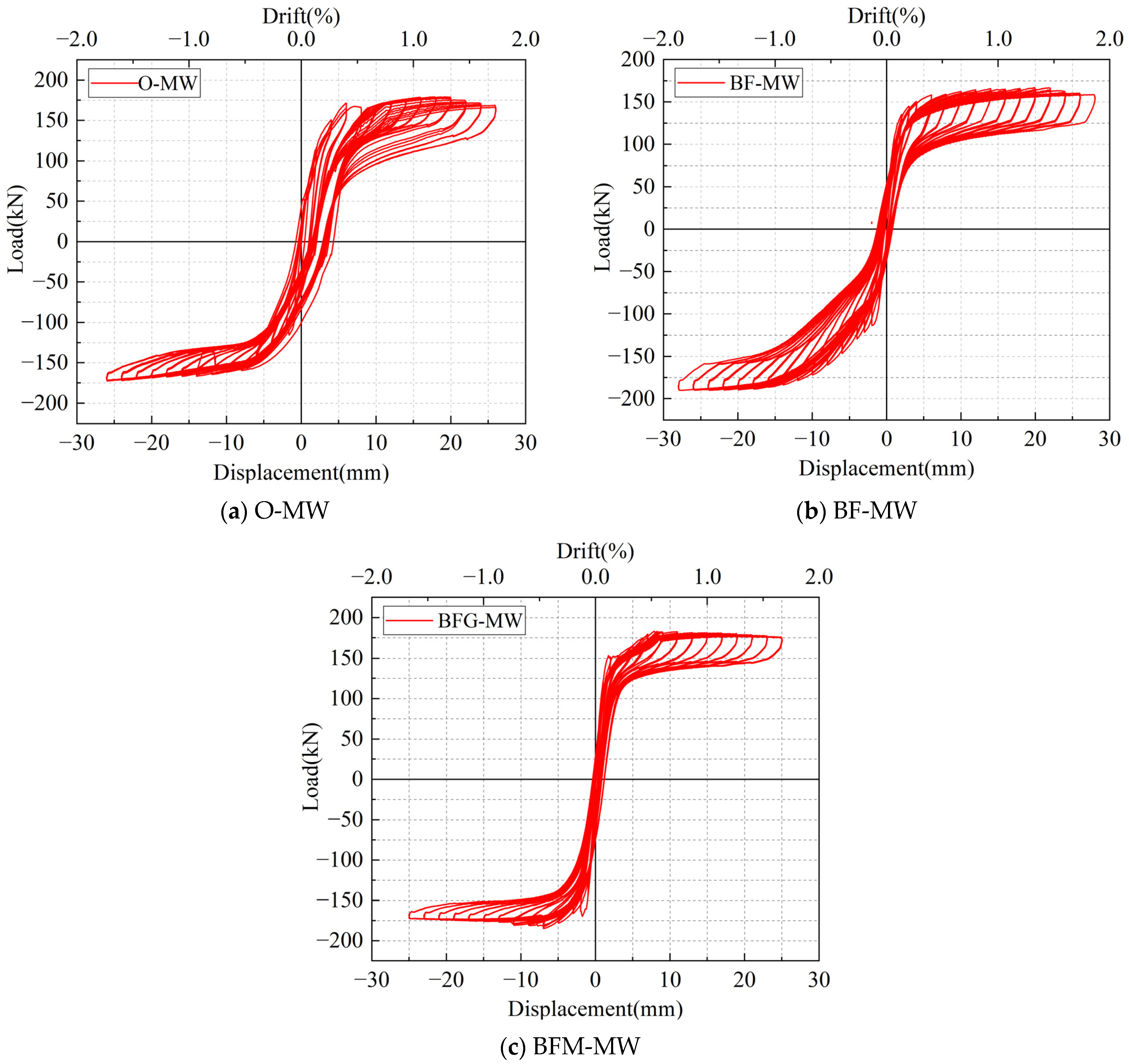
4.2.2. Hysteretic Curve
4.2.3. Backbone Curve
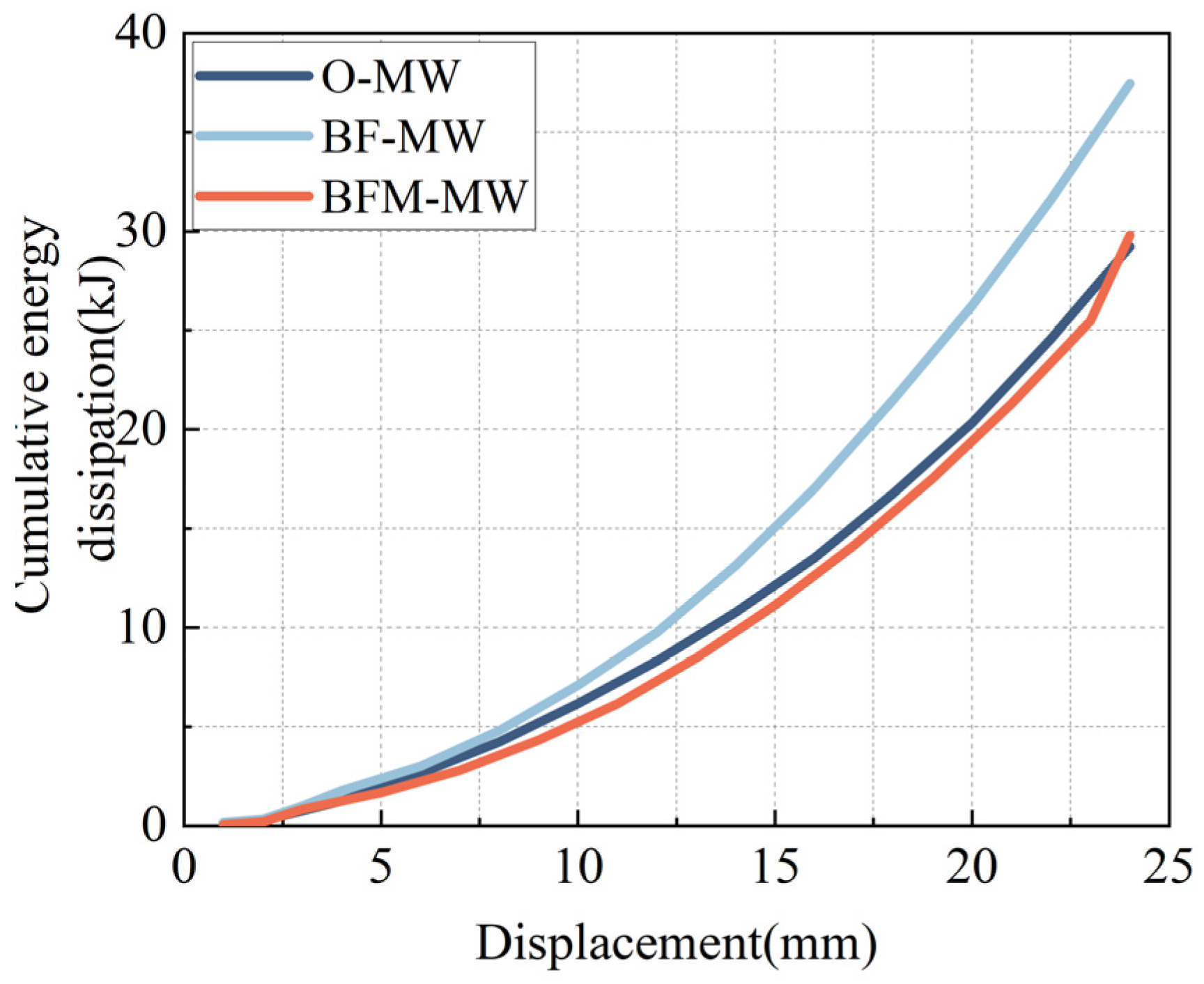
4.3. Energy Dissipation Calculation and Analysis
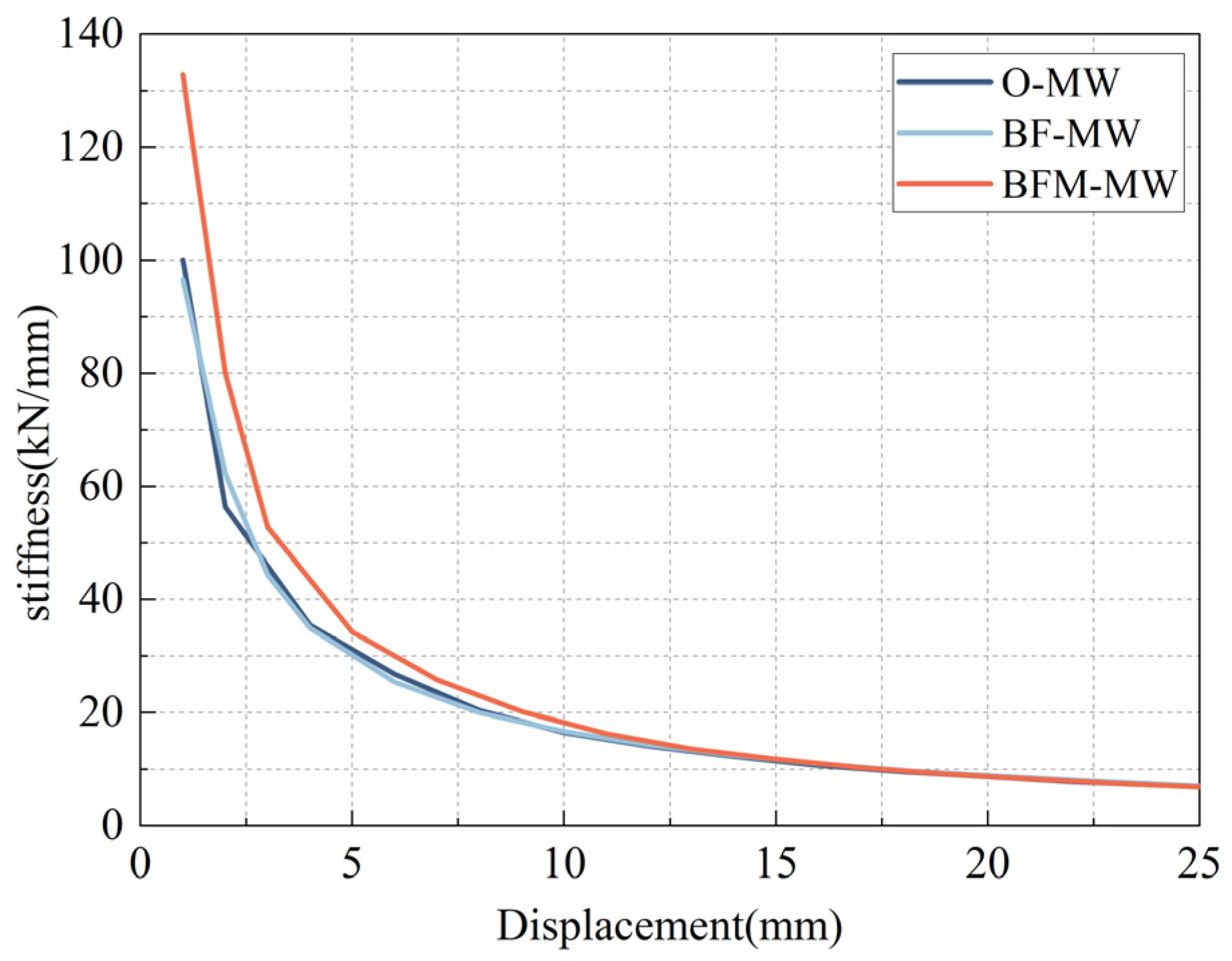
4.4. Degradation Curve of Stiffness
- (1)
- The stiffness degradation curves of all specimens exhibit a similar shape, comprising a sharp decline followed by a gradual leveling off. Specifically, the initial stiffness is high; as cracks develop and propagate, stiffness degradation becomes more pronounced. With increasing horizontal displacement, the masonry wall’s cracks coalesce into a main crack, and stiffness degradation stabilizes. When the displacement exceeds 13 mm, all specimens transition into bending–swaying walls, and their stiffness degradation curves completely overlap.
- (2)
- Specimen BFM-MW’s initial stiffness is 32.8% higher than that of the control specimen O-MW. Throughout the loading process, BFM-MW’s stiffness remains significantly greater than O-MW’s until it becomes a sway wall. This indicates that incorporating basalt fiber mesh into ordinary mortar substantially enhances the masonry wall’s stiffness and seismic performance. The primary reason is that basalt fiber mesh can suppress crack development, slow the decline in wall integrity, and thereby improve overall stiffness and delay degradation.
- (3)
- Specimen BF-MW’s stiffness degradation curve nearly coincides with that of the control specimen O-MW, suggesting that short-cut basalt fiber mortar and ordinary mortar have similar effects in strengthening the masonry wall’s surface layer. This similarity is mainly because both materials have equal strength, M15.
- (4)
- The stiffness degradation rates of all specimens are generally consistent. This consistency is due to the masonry walls’ inherent integrity and high stiffness, resulting in fewer cracks during loading. Consequently, the surface layer has minimal influence on the stiffness degradation rate.
5. Conclusions
- (1)
- Specimens O-MW and BF-MW exhibited bending failure, with through-thickness cracks forming at the bottom. However, specimen BF-MW had fewer cracks, indicating that basalt fibers can suppress crack formation. Specimen BFM-MW experienced shear failure, with distinct diagonal shear cracks, demonstrating that basalt fiber mesh can fully utilize the inherent strength of the wall.
- (2)
- Compared with the cracking load of specimen O-MW, those of specimens BFM-MW and BF-MW were increased by 41.6% and 10.3%, respectively, and peak loads increased by 3.9% and 1.5%, respectively. This indicates that basalt fiber mesh and basalt fibers can enhance the shear load-bearing capacity of masonry walls.
- (3)
- All the specimens’ hysteresis curves were S-shaped with significant “pinching” phenomena, primarily due to the sway–slip behavior observed in all specimens. In terms of energy dissipation, specimen BF-MW had cumulative energy dissipation and average energy dissipation coefficients 28.1% and 9% higher than those of specimen O-MW, respectively. Regarding stiffness degradation, specimen BF-MW’s initial stiffness was 32.8% higher than that of specimen O-MW, and its stiffness remained significantly higher during loading. This indicates that basalt fiber mortar provides a greater improvement in the energy dissipation capacity of the masonry wall, while basalt fiber mesh mortar is more effective in enhancing the stiffness of the masonry wall and its resistance to stiffness degradation.
- (4)
- In summary, through quasi-static experiments, it was found that basalt fiber materials can improve the seismic performance of masonry walls and alter the failure mode. Both forms of basalt fiber reinforcement have their respective advantages and disadvantages, and the reinforcement method can be selected according to the specific application scenario.
- (5)
- The test confirmed the positive effect of basalt fiber reinforcement on UMWs. However, the synergistic effects of basalt fiber-reinforced mortar and basalt fiber mesh-reinforced mortar on unreinforced masonry walls remain to be elucidated. Furthermore, the distinctions between the mechanisms of basalt fibers and other fiber types warrant further systematic comparative investigation.
- (6)
- The test focused on unreinforced masonry walls, with the specimen configuration limited to a single aspect ratio. However, the influence on walls with different aspect ratios and with openings still warrants further investigation, as well as the combined effects of these factors on UMWs.
Author Contributions
Funding
Data Availability Statement
Conflicts of Interest
References
- Xu, J.; Liang, J.G.; Yang, C.X. The current situation of masonry structure and its development suggestions. China Civ. Eng. J. 2022, 55, 1–6. [Google Scholar]
- Liang, X.X.; Li, B.X.; Peng, J. Experimental study on mechanical properties of fired hollow brick masonry. Build. Struct. 2015, 45, 90–95. [Google Scholar]
- Li, B.X.; Xie, H.P.; Deng, J.H.; He, C.; Wang, Z. Thoughts on earthquake characteristics and seismic design of buildings in Wenchuan earthquake. J. Disaster Prev. Mitig. Eng. 2009, 29, 224–230+236. [Google Scholar]
- Li, B.X.; Xie, H.P.; Wang, Z.; Wang, X. Wenchuan Earthquake Field Reconnaissance and Analysis on Multi-story Masonry Structure Buildings. Adv. Eng. Sci. 2009, 41, 19–25. [Google Scholar]
- Pan, Y.; Tang, L.; Wang, H.; Yao, Y. Investigation and analysis of damage to ancient buildings in Lushan Ms7.0 earthquake. Earthq. Eng. Eng. Dyn. 2014, 34, 145–151. [Google Scholar]
- Qu, Z.; Zhong, J.; Sun, J. Seismic damage to masonry structures in M7.0 Lunshan earthquake. J. Earthq. Eng. Eng. Vib. 2013, 33, 27–35. [Google Scholar]
- Isika, E.; Avcil, F.; Büyüksarac, A.; Izol, R.; Arslan, M.H.; Aksoylu, C.; Harirchian, E.; Eyisüren, O.; Arkan, E.; Güngürg, M.S.; et al. Structural damages in masonry buildings in Adiyaman during the Kahramanmaras, (Turkiye) earthquakes (Mw 7.7 and Mw 7.6) on 06 February 2023. Eng. Fail. Anal. 2023, 151, 28. [Google Scholar]
- Kocaman, I. The effect of the Kahramanmaras earthquakes (Mw 7.7 and Mw 7.6) on historical masonry mosques and minarets. Eng. Fail. Anal. 2023, 149, 107225. [Google Scholar]
- Isik, E.; Aydin, M.C.; Büyüksaraç, A. 24 January 2020 Sivrice (Elazig) earthquake damages and determination of earthquake parameters in the region. Earthq. Struct. 2020, 19, 145–156. [Google Scholar]
- Günaydin, M.; Atmaca, B.; Demir, S.; Altunisik, A.C.; Hüsem, M.; Adanur, S.; Ates, S.; Angin, Z. Seismic damage assessment of masonry buildings in Elazig and Malatya following the 2020 Elazig-Sivrice earthquake, Turkey. Bull. Earthq. Eng. 2021, 19, 2421–2456. [Google Scholar]
- Ingham, J.; Griffith, M. Performance of unreinforced masonry buildings during the 2010 Darfield (Christchurch, NZ) earthquake. Aust. J. Struct. Eng. 2011, 11, 207–224. [Google Scholar]
- Bilgin, H.; Leti, M.; Shehu, R.; Özmen, H.B.; Deringol, A.H.; Ormeni, R. Reflections from the 2019 Durres Earthquakes: An Earthquake Engineering Evaluation for Masonry Typologies. Buildings 2023, 13, 26. [Google Scholar] [CrossRef]
- Sherafati, M.A.; Sohrabi, M.R. Performance of Masonry Walls during Kaki, Iran, Earthquake of April 9, 2013. J. Perform. Constr. Facil. 2016, 30, 19. [Google Scholar]
- Sorrentino, L.; Cattari, S.; da Porto, F.; Magenes, G.; Penna, A. Seismic behaviour of ordinary masonry buildings during the 2016 central Italy earthquakes. Bull. Earthq. Eng. 2019, 17, 5583–5607. [Google Scholar]
- Naseer, A.; Khan, A.N.; Hussain, Z.; Ali, Q. Observed Seismic Behavior of Buildings in Northern Pakistan During the 2005 Kashmir Earthquake. Earthq. Spectra 2010, 26, 425–449. [Google Scholar]
- GB 50702-2011; Code for Design of Strengthening Masonry Structures. China Architecture and Building Press: Beijing, China, 2011.
- Kouris, L.A.S.; Triantafillou, T.C. State-of-the-art on strengthening of masonry structures with textile reinforced mortar (TRM). Constr. Build. Mater. 2018, 188, 1221–1233. [Google Scholar]
- Deng, M.K.; Zhang, W.; Yang, S. In -plane seismic behavior of autoclaved aerated concrete block masonry walls retrofitted with high ductile fiber -reinforced concrete. Eng. Struct. 2020, 219, 12. [Google Scholar]
- Zhou, T.G.; Liu, B.; Shi, Q.X.; Deng, M.K.; Deng, S.K. Experimental investigation on seismic behavior of cavity wall strengthened with ECC splint. World Earthq. Eng. 2019, 35, 157–166. [Google Scholar]
- Papanicolaou, C.G.; Triantafillou, T.C.; Karlos, K.; Papathanasiou, M. Textile-reinforced mortar (TRM) versus FRP as strengthening material of URM walls: In-plane cyclic loading. Mater. Struct. 2007, 40, 1081–1097. [Google Scholar]
- Nadège, R.; Zyed, M.; Amir, S.L.; Emmanuel, F. Experimental study of the in-plane cyclic behaviour of masonry walls strengthened by composite materials. Constr. Build. Mater. 2018, 164, 70–83. [Google Scholar]
- Deng, Z.C.; Chen, C.C.; Zhu, X.N.; Xu, X.H.; Zhao, M.Y. Experimental Study of Seismic Performance of Masonry Walls Strengthened with CFN. J. Tianjin Univ. (Sci. Technol.) 2019, 52, 1090–1098. [Google Scholar]
- Augenti, N.; Parisi, F.; Prota, A.; Manfredi, G. In-Plane Lateral Response of a Full-Scale Masonry Subassemblage with and without an Inorganic Matrix-Grid Strengthening System. J. Compos. Constr. 2011, 15, 578–590. [Google Scholar] [CrossRef]
- Gattesco, N.; Amadio, C.; Bedon, C. Experimental and numerical study on the shear behavior of stone masonry walls strengthened with GFRP reinforced mortar coating and steel-cord reinforced repointing. Eng. Struct. 2015, 90, 143–157. [Google Scholar] [CrossRef]
- Zhou, T.G.; Zhang, Z.Y.; Deng, M.K.; Fan, X.M. Effect of different ECC reinforcement measures on the seismic performance of cavity-wall. J. Vib. Shock. 2020, 39, 248–253. [Google Scholar]
- Deng, M.K.; Fan, X.M.; Gao, X.J.; Liang, X.W. Experimental investigation on seismic behavior of damaged brick masonry wall strengthened with ECC splint. Eng. Mech. 2015, 32, 120–129. [Google Scholar]
- Wang, Z.L.; Li, X.M.; Gao, R.D.; Zhang, Y.Q.; Xu, Q.F. Experimental research on seismic performance of brick walls strengthened by fiber-reinforced cement-based composite material surface layer. Build. Struct. 2021, 51, 17–25+16. [Google Scholar]
- Zhang, W.; He, J.J.; Hu, W.; Pan, J.J.; Deng, M.K. Study on seismic behavior and bearing capacity of concrete masonry wall retrofitted using high ductile fiber-reinforced concrete. Eng. Mech. 2024, 1–14. [Google Scholar]
- Facconi, L.; Minelli, F.; Lucchini, S.; Plizzari, G. Experimental Study of Solid and Hollow Clay Brick Masonry Walls Retrofitted by Steel Fiber-Reinforced Mortar Coating. J. Earthq. Eng. 2020, 24, 381–402. [Google Scholar] [CrossRef]
- Liu, G.A.; Wang, X.; Yang, Z.; Wang, L.Y.; Zhou, Y.W.; Chen, G.B. Experimental Study on Seismic Performance of Confined Masonry Walls With Window Openings Strengthened by Using Hybrid-Fiber Modified Reactive Powder Concrete. Front. Mater. 2022, 9, 17. [Google Scholar] [CrossRef]
- Arslan, M.E.; Aykanat, B.; Ayyildiz, M.A.; Subasi, S.; Marasli, M. Effects of basalt and glass fiber composites usage for strengthening on the cyclic behavior of brick infill walls. J. Build. Eng. 2022, 52, 104405. [Google Scholar] [CrossRef]
- Du, Y.F.; Kou, J.L.; Yang, J.C.; Yan, L.; Zhao, F.C. Experimental investigation of aseismatic behavior of wall body with perforated brick masonry reinforced by cement mortar. Journal of Lanzhou University of Technology 2009, 35, 107–110. [Google Scholar]
- Wei, C. Study on Seismic Performance of Masonry Wall Reinforced by Basalt Fiber Concrete Surface Layer; Chang’an University: Xi’an, China, 2024. [Google Scholar]
- Meriggi, P.; Caggegi, C.; Gabor, A.; de Felice, G. Shear-compression tests on stone masonry walls strengthened with basalt textile reinforced mortar (TRM). Constr. Build. Mater. 2022, 316, 16. [Google Scholar]
- Garcia-Ramonda, L.; Pelà, L.; Roca, P.; Camata, G. Cyclic shear-compression testing of brick masonry walls repaired and retrofitted with basalt textile reinforced mortar. Compos. Struct. 2022, 283, 14. [Google Scholar]
- Chen, S.F.; Wang, J.Y.; Shen, J.; Wan, C.L.; Hu, X.R.; Liu, C.B.; Hu, Z.H. Quasi-static tests of masonry walls strengthened with textile reinforced concrete on one side. Concrete 2022, 4, 56–60. [Google Scholar]
- GB/T 2542-2012; Test Methods for Wall Bricks. Standardization Administration of China: Beijing, China, 2012.
- JGJ/T 70-2009; Standard for Test Method of Basic Properties of Construction Mortar. Ministry of Housing and Urban-Rural Development of the People’s Republic of China: Beijing, China, 2009.
- JGJ/T 101-2015; Specification for Seismic Test of Buildings. Ministry of Housing and Urban-Rural Development of the People’s Republic of China: Beijing, China, 2015.


| Diameter (um) | Length (mm) | Density (g/cm3) | Tensile Strength (MPa) | Modulus of Elasticity (GPa) | Elongation (%) |
|---|---|---|---|---|---|
| 17 | 17.78 | 2.7 | 2400 | 86 | 2.8 |
| Mesh Density | Weight | Longitudinal Tensile Fracture Strength | Latitudinal Tensile Fracture Strength |
|---|---|---|---|
| 6/25 mm | 113.9 g/m2 | 1802 N/(50 × 100 mm) | 1385 N/(50 × 100 mm) |
| No. | 1 | 2 | 3 | 4 | 5 | 6 | 7 | 8 | 9 | 10 | Average |
|---|---|---|---|---|---|---|---|---|---|---|---|
| Ultimate Load (kN) | 575.8 | 578.7 | 512.3 | 523.8 | 497.3 | 563.7 | 528.9 | 487.3 | 476.3 | 502.5 | 524.7 |
| Compression Strength (MPa) | 20.9 | 21.0 | 18.6 | 19.0 | 18.0 | 20.4 | 19.2 | 17.7 | 17.3 | 18.2 | 19.0 |
| Mortar Types | No. | 1 | 2 | 3 | 4 | 5 | 6 | Average |
|---|---|---|---|---|---|---|---|---|
| Masonry Mortar | Ultimate Load (kN) | 47.4 | 50.5 | 45.1 | 36.2 | 33.8 | 45.9 | 43.2 |
| Compression Strength (MPa) | 9.5 | 10.1 | 9.0 | 7.2 | 6.8 | 9.2 | 8.6 | |
| M15 Mortar | Ultimate Load (kN) | 85.3 | 86.2 | 92.3 | 79.5 | 95.8 | 75.9 | 85.8 |
| Compression Strength (MPa) | 17.1 | 17.2 | 18.5 | 15.9 | 19.2 | 15.2 | 17.2 | |
| Basalt Rock Fiber Mortar | Ultimate Load (kN) | 78.9 | 85.6 | 62.3 | 96.3 | 78.4 | 86.9 | 81.4 |
| Compression Strength (MPa) | 15.8 | 17.1 | 12.5 | 19.3 | 15.7 | 17.4 | 16.3 |
| Cracking Load Pcr (kN) | Rise (%) | Peak Load PP (kN) | Rise (%) | |||||
|---|---|---|---|---|---|---|---|---|
| + | − | Average | + | − | Average | |||
| O-MW | 116.7 | 109.0 | 112.9 | — | 179.2 | 172.3 | 175.8 | — |
| BF-MW | 135.3 | 113.7 | 124.5 | 10.3 | 166.9 | 190.0 | 178.5 | 1.5 |
| BFM-MW | 151.7 | 168.1 | 159.9 | 41.6 | 182.3 | 183.1 | 182.7 | 3.9 |
| Final Cumulative Energy (kJ) | Rise (%) | |
|---|---|---|
| O-MW | 29.2 | — |
| BF-MW | 37.4 | 28.1 |
| BFM-MW | 29.8 | 2.1 |
| Final Cumulative Energy (kN/mm) | Rise (%) | |
|---|---|---|
| O-MW | 100.1 | — |
| BF-MW | 96.6 | −3.5 |
| BFM-MW | 132.8 | 32.8 |
Disclaimer/Publisher’s Note: The statements, opinions and data contained in all publications are solely those of the individual author(s) and contributor(s) and not of MDPI and/or the editor(s). MDPI and/or the editor(s) disclaim responsibility for any injury to people or property resulting from any ideas, methods, instructions or products referred to in the content. |
© 2025 by the authors. Licensee MDPI, Basel, Switzerland. This article is an open access article distributed under the terms and conditions of the Creative Commons Attribution (CC BY) license (https://creativecommons.org/licenses/by/4.0/).
Share and Cite
Wang, Y.; Li, B.; Nong, Q.; Liu, X. Quasi-Static Testing of Unreinforced Masonry Walls Using Different Styles of Basalt Fiber Mortar Surface Reinforcements. Buildings 2025, 15, 1074. https://doi.org/10.3390/buildings15071074
Wang Y, Li B, Nong Q, Liu X. Quasi-Static Testing of Unreinforced Masonry Walls Using Different Styles of Basalt Fiber Mortar Surface Reinforcements. Buildings. 2025; 15(7):1074. https://doi.org/10.3390/buildings15071074
Chicago/Turabian StyleWang, Yize, Bixiong Li, Qingshun Nong, and Xing Liu. 2025. "Quasi-Static Testing of Unreinforced Masonry Walls Using Different Styles of Basalt Fiber Mortar Surface Reinforcements" Buildings 15, no. 7: 1074. https://doi.org/10.3390/buildings15071074
APA StyleWang, Y., Li, B., Nong, Q., & Liu, X. (2025). Quasi-Static Testing of Unreinforced Masonry Walls Using Different Styles of Basalt Fiber Mortar Surface Reinforcements. Buildings, 15(7), 1074. https://doi.org/10.3390/buildings15071074