3.1. Experimental Phenomena and Failure Characteristics
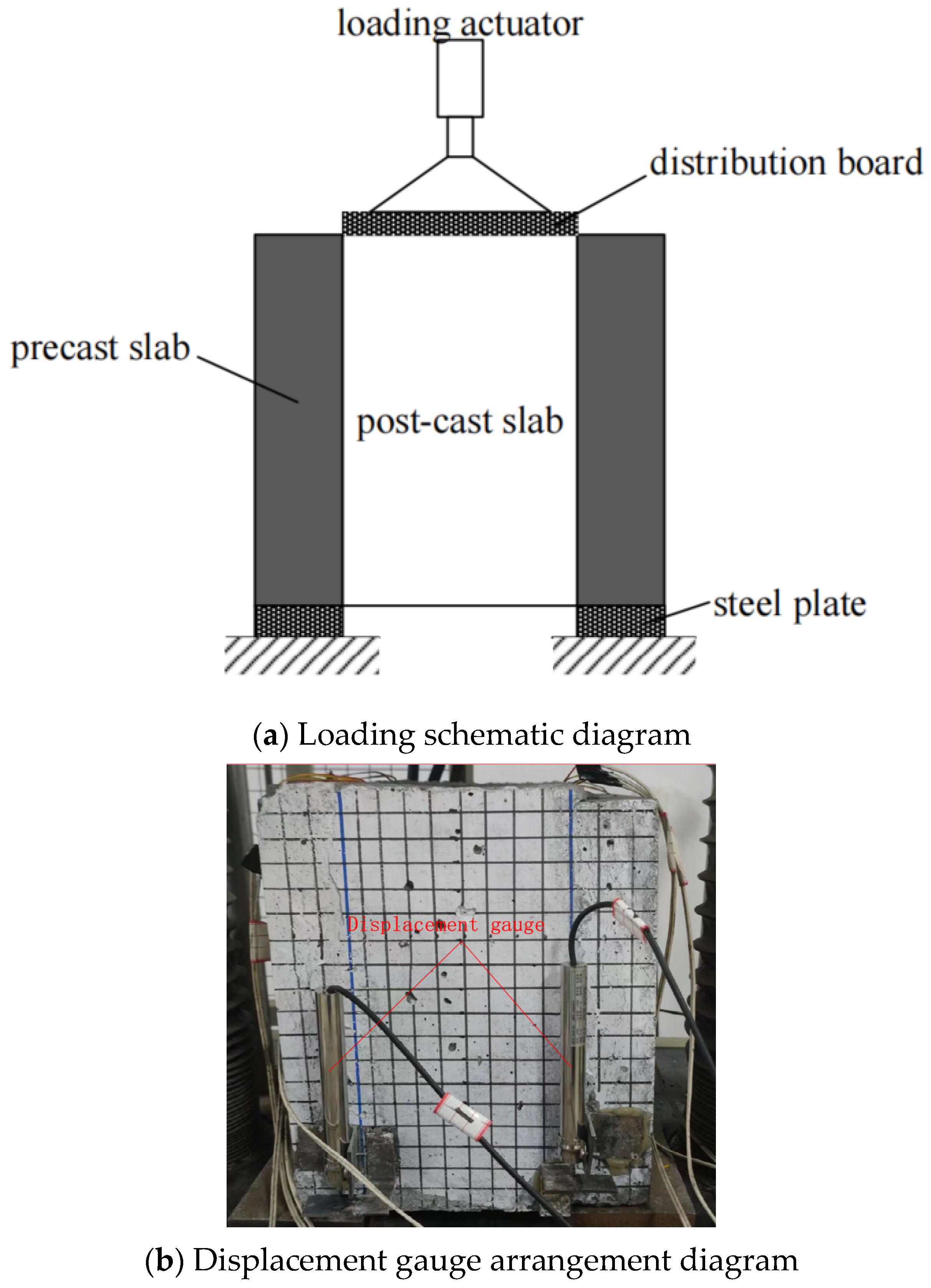
The experimental results show that all specimens failed in a brittle manner, and their failure modes were basically consistent. Taking specimen TH3-2 as an example, from the beginning of loading until failure, there were no obvious signs of damage. When the load reached the ultimate load of 571.9 kN (the shear force on the composite interface was 571.9 kN/2 = 285.95 kN), the specimen suddenly emitted a dull sound, and a full-length vertical crack appeared on both sides of the composite interface. Thereafter, the load rapidly decreased, the displacement continued to increase, and the specimen lost its bearing capacity.
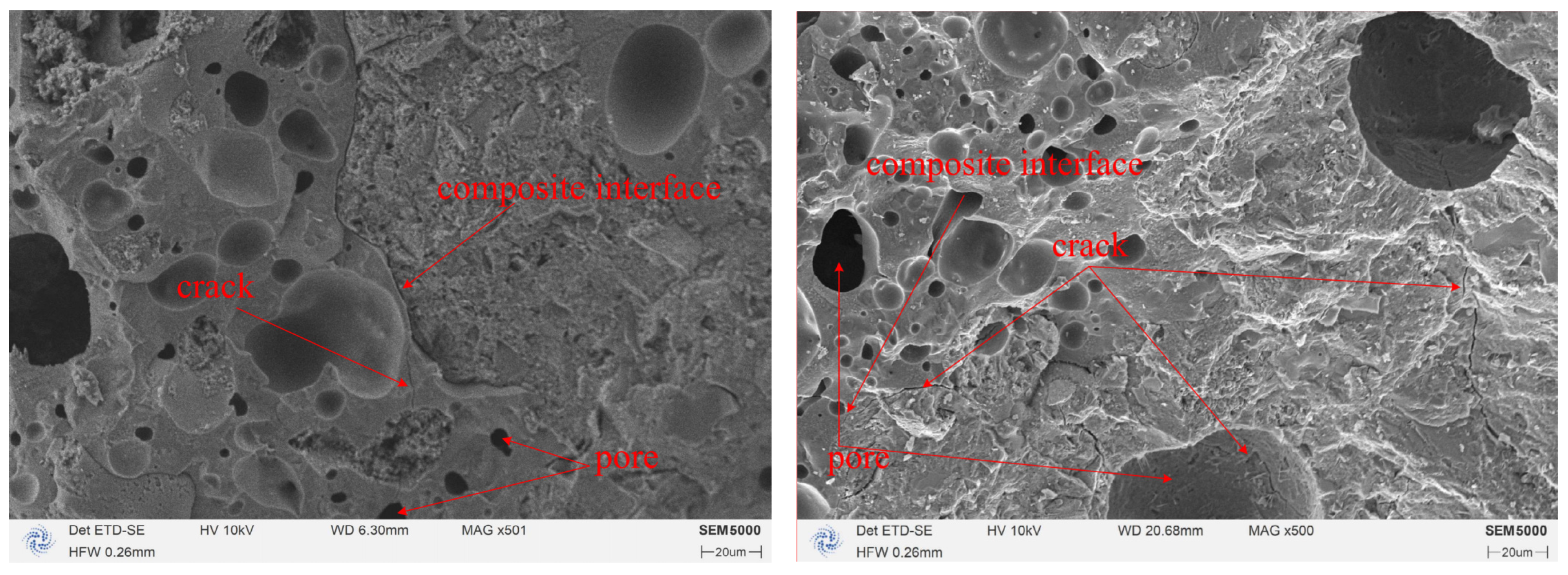
During loading, shear stress was generated within the loading plane of the specimen, and its direction was parallel to the loading direction. Concrete is a composite material composed of porous, multiphase substances with cracks, and there are potential internal defects in its structure. The failure of the concrete structure begins with the initiation of cracking due to high stress concentration around these potential microcracks under load. After a relatively stable crack development process, it expands into unstable cracks, eventually leading to complete failure of the concrete structure. As shown in
Figure 5, the SEM characterization of the ceramsite concrete specimen after failure clearly reveals that concrete is a porous and multiphase material. Crack propagation predominantly occurs at pores or interfaces. When the shear stress reaches the ultimate failure value, the specimen is sheared into two halves. The failure mechanism of the composite concrete bonded specimens is basically the same as that of monolithically cast concrete, except that the internal potential defects are more severe and the internal stress is more complex. Therefore, the mechanical properties of composite concrete bonded specimens are lower than those of monolithically cast concrete. The main failure mode of each specimen is the relative slip between the new and old concrete on both sides of the composite interface, and cracks appear along the shear direction on the composite interface.
The mechanical behavior of the reinforced truss ceramsite concrete composite interface can be divided into three stages:
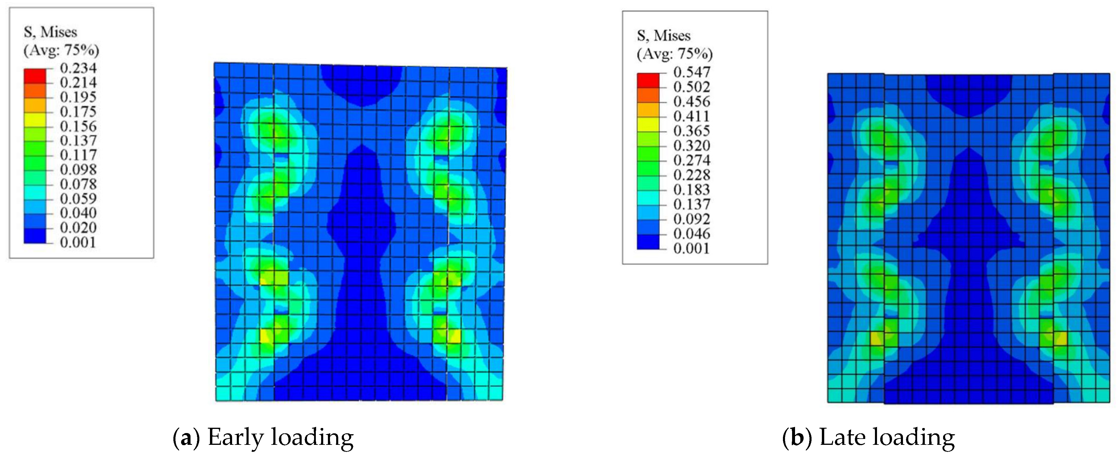
First Stage: In the early stage of loading, before cracks appear on the composite interface between new and old concrete and within the concrete itself, the interface slip only involves the shear deformation of the interface concrete. At this time, the stiffness of the interface is large, so the slip between interfaces is very small, which is also reflected in the experiment—the collected data show that the maximum displacement at ultimate bearing capacity is only 0.15 mm. As the load continues to increase, since the load is applied to the new concrete, due to the combined action of compression and shear, the new concrete transfers the shear force at the interface to the old concrete through the truss reinforcement. The concentrated force of the truss reinforcement acting on the new concrete is transmitted to the interface between new and old concrete in the form of an oblique compressive stress flow, so inclined cracks will appear in the new concrete. In the experiment, half of the specimens’ post-cast composite layers exhibited inclined cracks developing from the composite interface toward the loading center.
Second Stage: As the load continues to increase to the ultimate bearing capacity, the stress state of the composite concrete reaches the interface’s stress failure plane and fails. Part of the stress at the interface of the new concrete is released and borne by the web reinforcements of the truss and the upper and lower chord reinforcements passing through the inclined cracks. The reinforcements transition from the elastic stage to the plastic stage, and the composite concretes gradually separate. Because the shear stiffness of the reinforcements is relatively small, there will be a certain amount of slip from the load-bearing stage to the reinforcement yielding stage. Thereafter, the reinforcements enter the yielding stage, and the load maintains a constant value without further increase.
Third Stage: The load remains constant while the slip between the composite interfaces continues to increase. All web reinforcements enter the yielding stage, rigid body motion occurs between the composite concretes, and the interface completely enters the plastic stage.
The three-phase shear behavior (elastic deformation, plastic softening, and full yielding) identified in this study has critical implications for real-world construction practices. For instance:
Elastic Phase: In prefabricated building systems, the elastic phase corresponds to the serviceability limit state where composite interfaces must maintain minimal slip under routine loads (e.g., wind or live loads). Ensuring adequate interfacial stiffness during this phase is vital for structural integrity and occupant safety.
Plastic Softening: This phase may manifest in scenarios involving localized overloading or fatigue (e.g., bridge deck retrofits). The gradual reduction in shear stiffness highlights the need for redundancy in reinforcement design to prevent sudden failures.
Full Yielding: Structural retrofits in seismic zones must account for this phase, as yielding of truss reinforcements could act as an energy-dissipation mechanism. However, excessive slip at this stage may compromise post-earthquake reparability, necessitating strict control of reinforcement ratios.
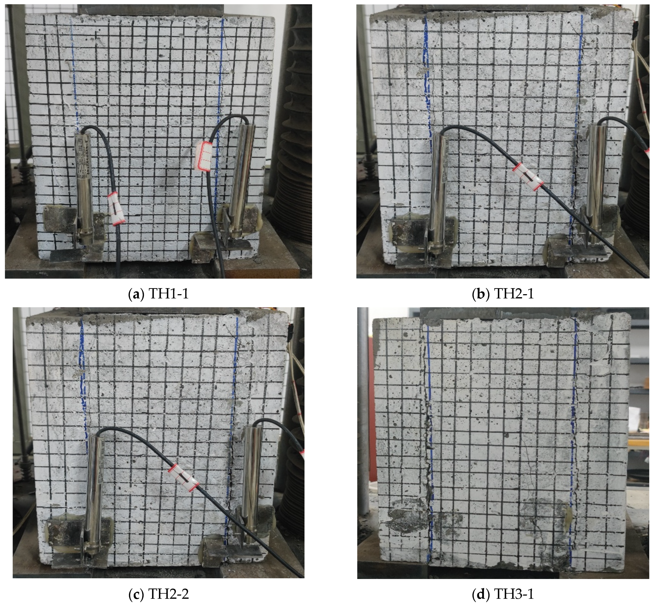
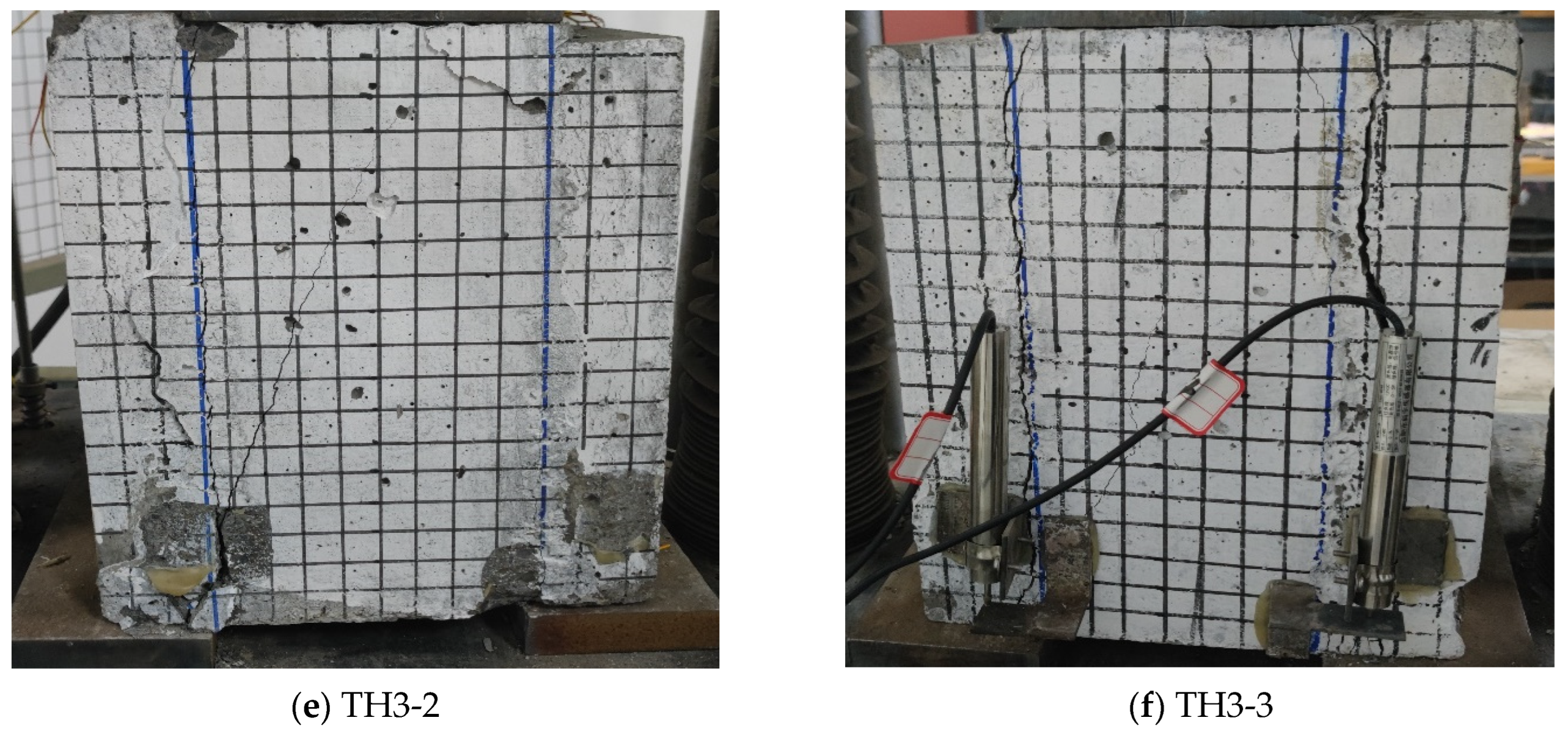
The failure modes of each specimen are shown in
Figure 6; no cracks were found in the precast slabs.
3.2. Analysis of Shear-Bearing Capacity
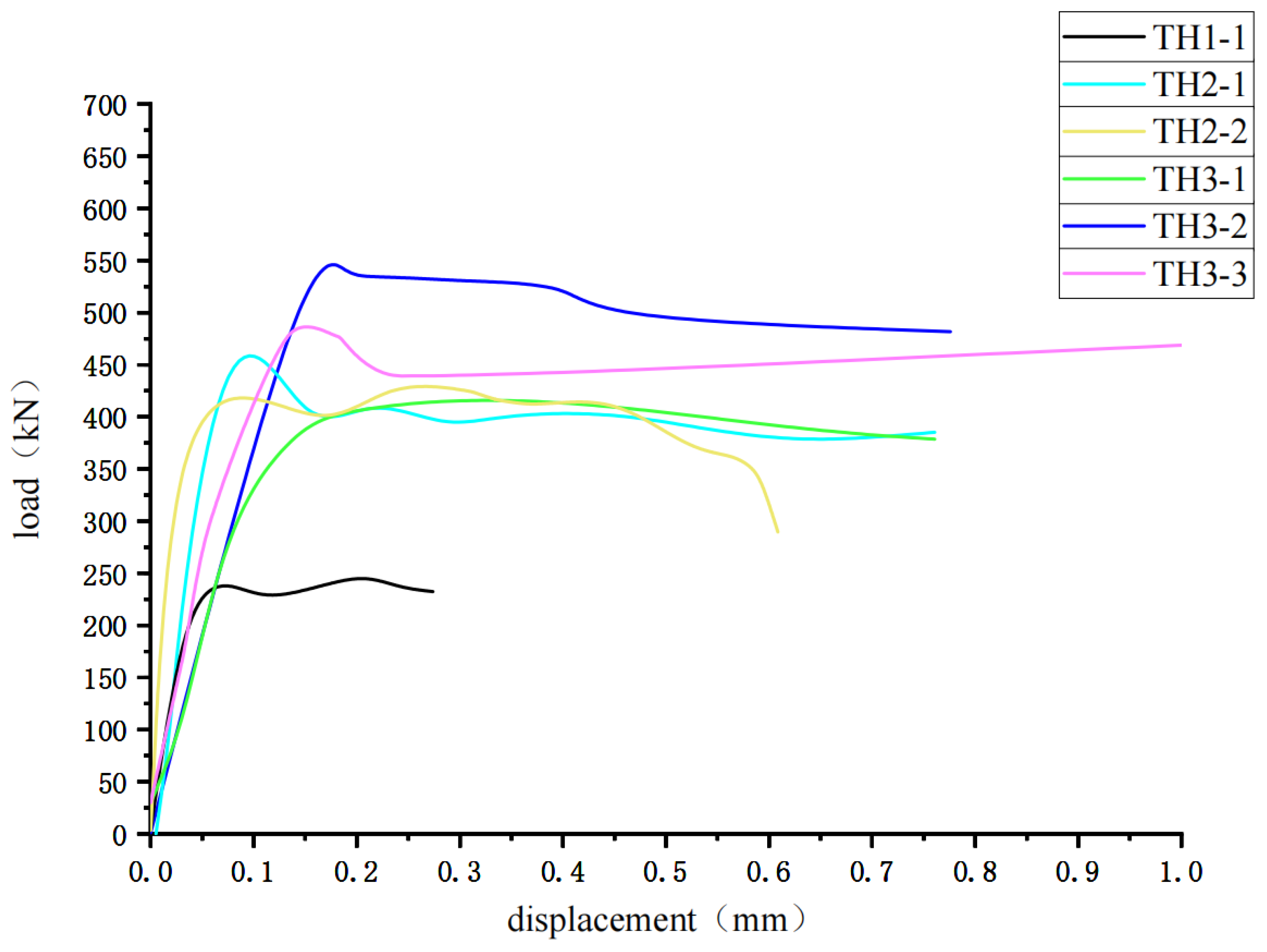
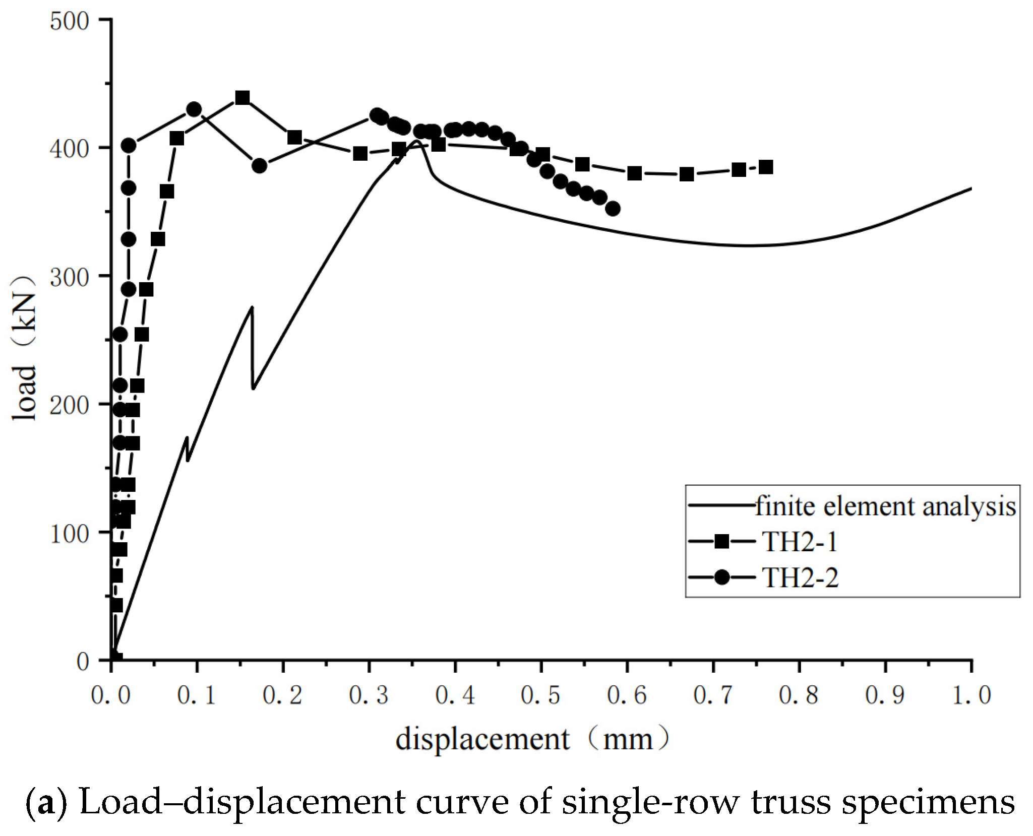
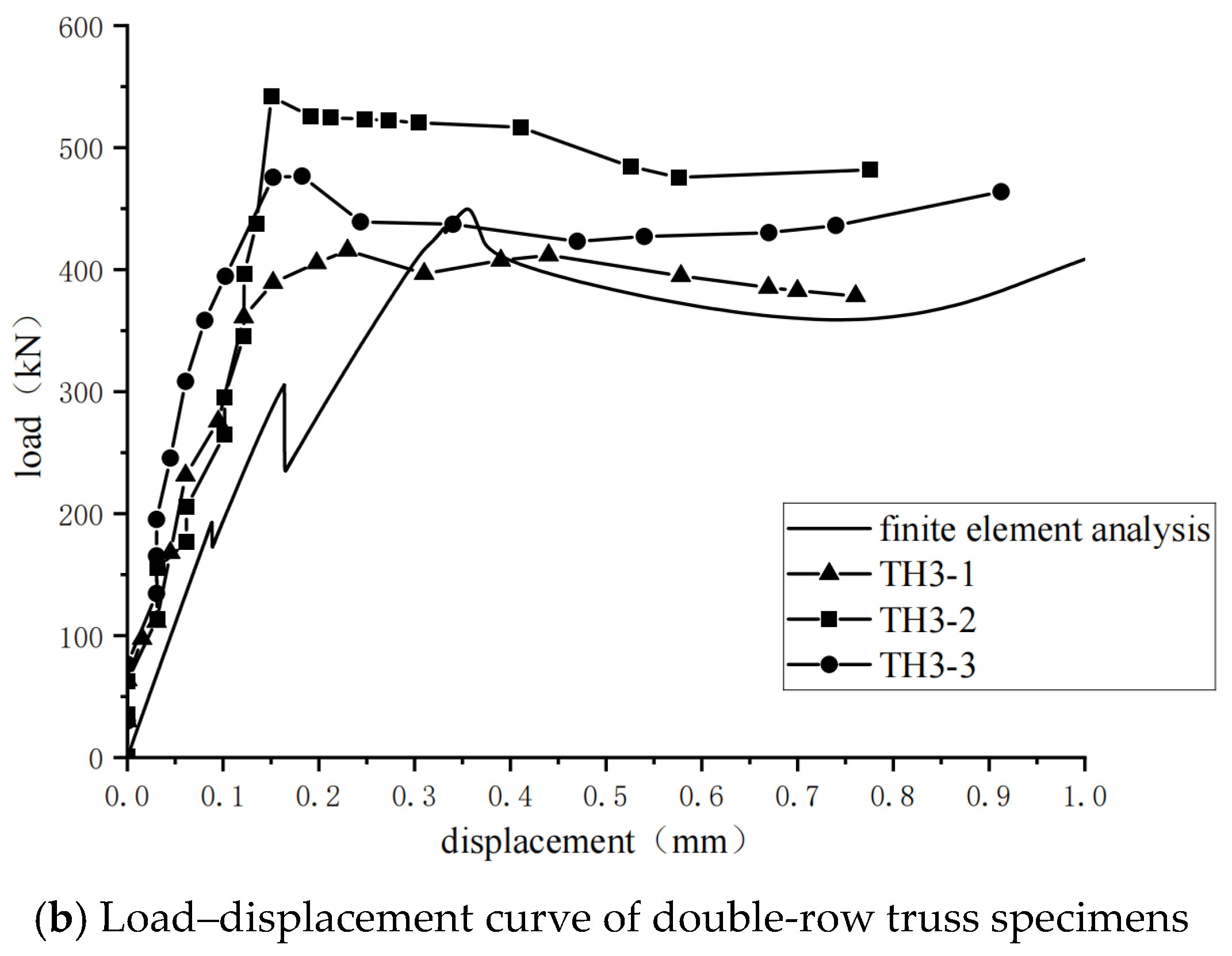
Figure 7 shows the variation in relative displacement between the precast slab and the composite layer with the load. The experimental results indicate that the web reinforcements of the reinforcement truss have a significant impact on the shear-bearing capacity of the composite interface. In the early stage of loading, the shear-bearing capacity is mainly contributed by bonding force and friction. In the later stage of loading, the web reinforcements play a role in resisting shear at the composite interface. When the shear-bearing capacity of the composite interface is insufficient, relative slip cracks appear at the interface, and the specimen loses its bearing capacity. Under similar roughness conditions, the shear-bearing capacity of specimens without reinforcement is smaller than that of specimens with reinforcement. Compared with specimens without truss reinforcement, the shear-bearing capacity of specimens with a single row of reinforcement truss increased by 75.6%. Compared with specimens with a single row of reinforcement truss, those with a double row showed a 13.2% increase in shear-bearing capacity.
The limited 13.2% increase in the shear capacity of double-row truss specimens compared to single-row specimens can be attributed to several factors. Firstly, the stress concentration effect is more pronounced in double-row truss specimens, which may exacerbate interfacial stress concentration and diminish shear stiffness. During loading, this stress concentration can accelerate the propagation and penetration of interfacial cracks, thereby reducing the shear stiffness. Secondly, the presence of double-row trusses may compromise the uniformity of concrete pouring, leading to a decline in interfacial bonding quality and the emergence of localized poor adhesion. Consequently, the overall shear performance is weakened, restricting the improvement in shear capacity of double-row truss specimens. Moreover, from the perspective of structural optimization, in the structural configuration of this study, single-row trusses are usually sufficient to meet most bearing requirements. When an extra row of trusses is added, the resulting effects may tend to saturate, failing to significantly enhance.
It is generally considered that the shear-bearing capacity
of the interface between new and old concrete includes the bonding force
between interfaces, the friction force
between interfaces, the dowel action
of shear reinforcement, and the component
of shear reinforcement in the direction of the composite interface [
43], that is:
Since the dowel action is difficult to calculate, the calculation formulas in these codes do not consider the dowel action.
Figure 8 illustrates the components of the tensile force
in the web reinforcement in various directions. From the figure, it can be seen that the calculation methods for its component perpendicular to the composite interface
and its component parallel to the composite interface
are as follows:
It can be seen that the spatial positioning of the web reinforcement has a certain impact on the shear-bearing capacity of the composite interface.
Currently, the codes in Europe, the United States, Canada, and China all consider the influence of reinforcement on the shear-bearing performance of concrete composite interfaces. To accurately determine the shear-bearing capacity of the reinforced ceramsite concrete interfaces, a comparative analysis of the applicability of shear capacity formulas from various codes to ceramsite concrete composite interfaces is conducted below. To facilitate comparison with the experimental results, the strength values in the calculation formulas are all taken as standard values; that is, the material partial factors in the formulas are all set to 1.0, and the units are unified as N, mm, and MPa.
3.2.1. Eurocode 2
The European code [
38] (hereinafter referred to as Eurocode 2) specifies the method for calculating the shear stress
at the interface between the new and old concrete as:
where:
—coefficient reflecting bond stress;
—axial tensile strength of concrete on both sides of the interface;
—friction coefficient;
—reinforcement ratio of shear reinforcement at the composite interface;
—yield strength of shear reinforcement;
—angle between web reinforcement and shear plane;
—normal stress generated by the minimum interface normal force acting simultaneously with the interface shear force.
c and μ are coefficients determined by the interface roughness, and their values are related to the average roughness
, as shown in
Table 3.
can be measured using the sand-patch method; according to
Table 3, the values of c and μ are 0.7 and 0.45, respectively.
3.2.2. ACI 318-19
The American Concrete Institute’s standard [
39] ignores the bonding force and the normal stress generated by permanent actions, that is:
The friction coefficient μ is determined based on the roughness of the interface, and when lightweight concrete is used, the friction coefficient needs to be reduced; see
Table 4.
3.2.3. CSA A23.3-04
The Canadian Standards Association’s standard [
40] (CSA A23.3-04) considers the bonding force and the normal stress generated by permanent actions, that is:
where
has the same meaning and value as in the American code, and
is the bonding stress;
.
The values of λ and μ depend on the surface roughness, according to
Table 5.
3.2.4. GB 50010-2010
GB 50010-2010 “Code for Design of Concrete Structures” [
41] provides corresponding provisions for the shear-bearing capacity of composite interfaces in composite beams and slabs. When the composite beam meets all structural requirements, the shear-bearing capacity of the composite interface satisfies:
where Q is the shear force of the member; b is the width of the cross-section;
is the effective depth of the cross-section; and
is the design value of the tensile strength of concrete, taking the lower value between the composite layer and the precast concrete.
Table 6 presents the ultimate shear-bearing capacity and corresponding shear stress of the specimen–composite interfaces.
Dividing both sides of Equation (1) by
, and ignoring the dowel action, the shear stress in various regional codes can be uniformly expressed as:
where
is the shear stress component provided by bonding force;
is the shear stress component provided by friction force; and
is the shear stress component provided by shear reinforcement.
Using Equations (2) and (3), and
, the shear stress components corresponding to each calculation formula can be obtained, as shown in
Table 7. Since the Chinese code’s calculation formula is applicable to composite beams with stirrups (perpendicular to the composite interface), the friction force is multiplied by
to consider the inclined web reinforcement. According to the material test results and reinforcement specifications,
,
,
,
,
.
The theoretical calculation results obtained from
Table 7 are listed in
Table 8 (
).
It can be seen that there are significant differences in the ultimate shear-bearing capacity of ceramsite concrete interfaces obtained from different regional codes. The results calculated using the European code are the closest to the experimental results. The shear-bearing capacity of reinforced truss ceramsite concrete composite interfaces follows a pattern similar to that of ordinary concrete.
3.3. Shear Stiffness Analysis
The average shear stress and shear stiffness of the interface can be calculated according to Equation (10) [
37].
In the formula:
—Shear force acting on the interface (N)
—Interface area (mm2)
—Interface shear stiffness (MPa/mm)
—Difference in shear stress on the interface (MPa)
—Difference in interface slip (mm)
The shear stiffness of each specimen in the elastic stage is shown in
Table 9.
In the experiment, the shear stiffness of specimens with two rows of reinforcement trusses was lower than that of specimens without reinforcement trusses, and the specimens without reinforcement trusses were lower than those with only one row of reinforcement trusses. This phenomenon may be due to the increased number of trusses leading to more significant stress concentration at the interface, thereby reducing the shear stiffness. The two rows of reinforcement trusses may guide the concentrated development of cracks during loading, causing the cracks to penetrate faster, leading to a decrease in shear stiffness. Additionally, the dense arrangement of trusses may affect the uniformity of concrete pouring, leading to decreased interface bonding quality and the appearance of local poor bonding areas, thus weakening the overall shear performance. In contrast, in specimens with only one row of reinforcement trusses, concrete vibration and pouring are more adequate, resulting in relatively better bonding quality and thereby improving the shear stiffness.


