

Architectural Study and Preliminary Seismic Assessment of a Typical Unreinforced Brick Masonry Building in Zagreb, Croatia


Abstract
1. Introduction
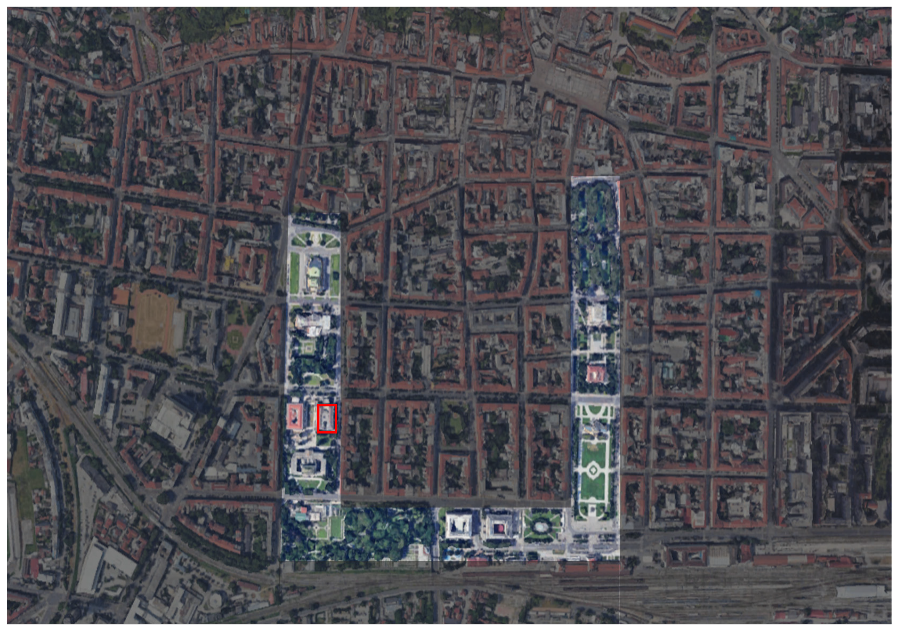
2. Case Study
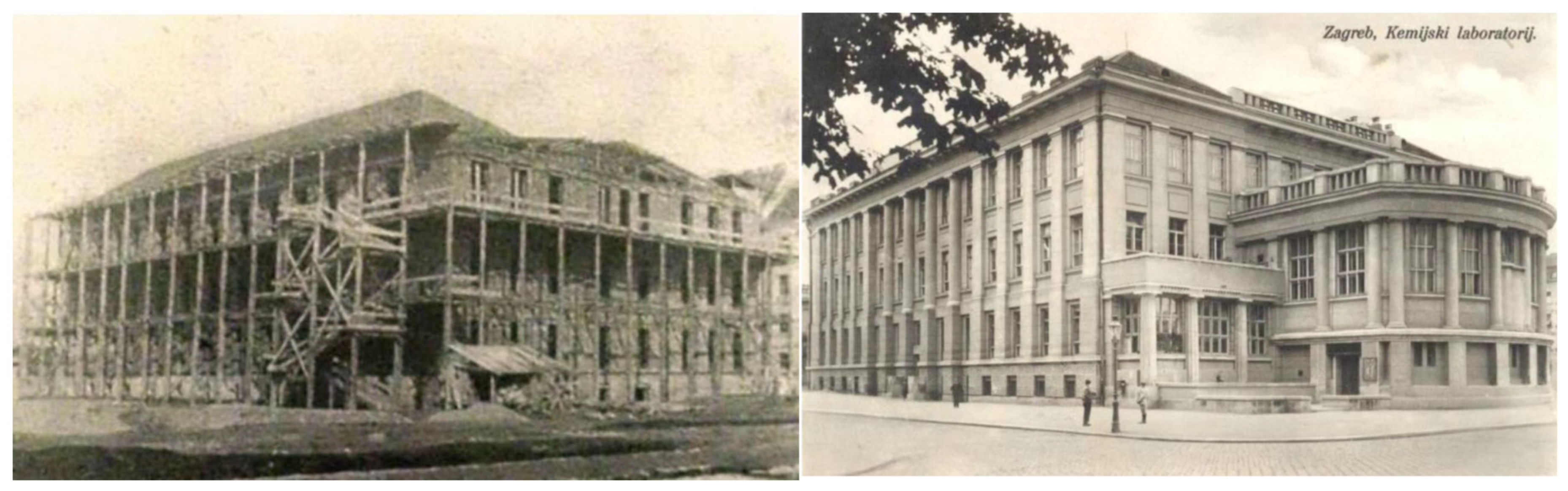
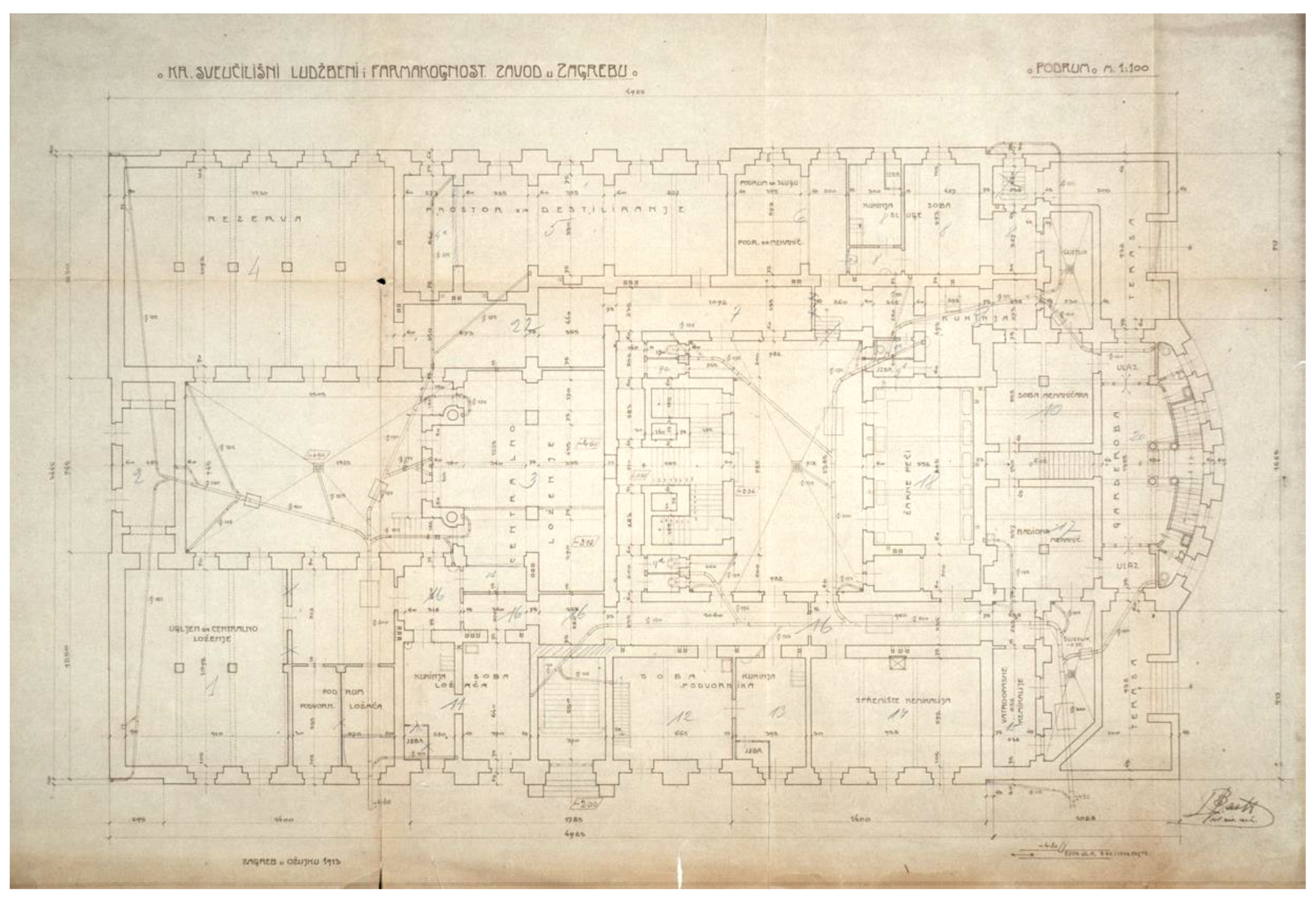
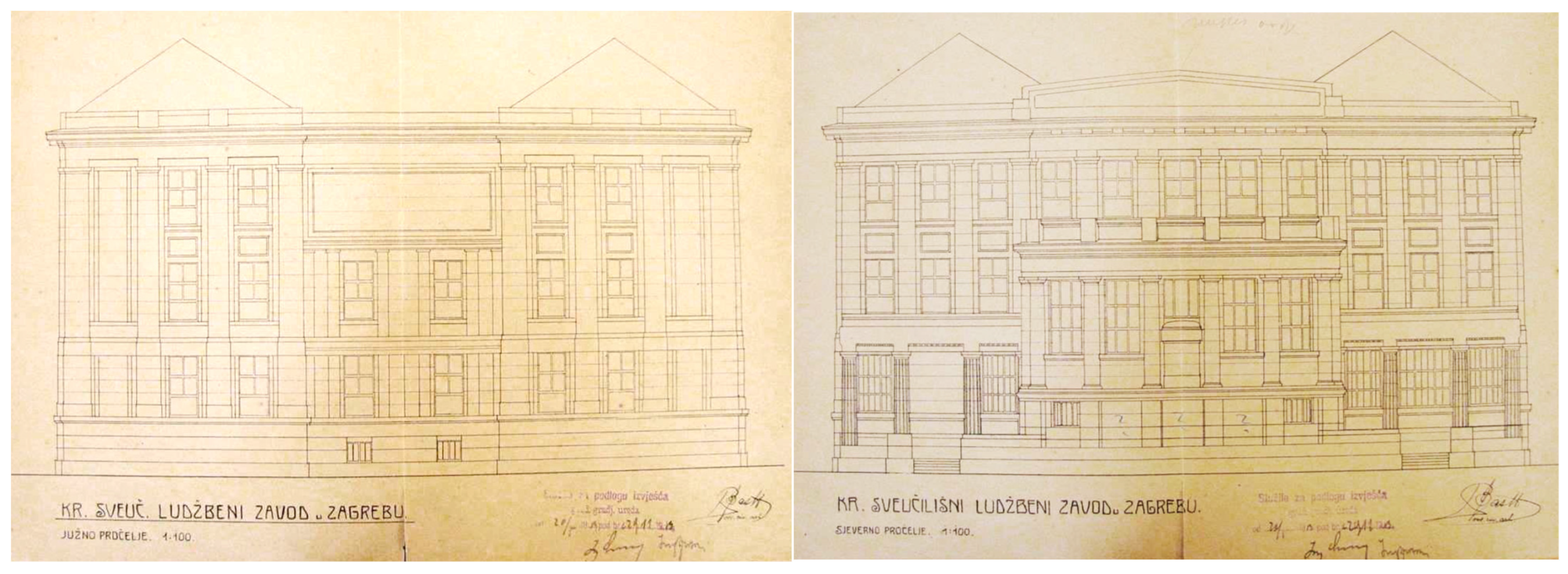
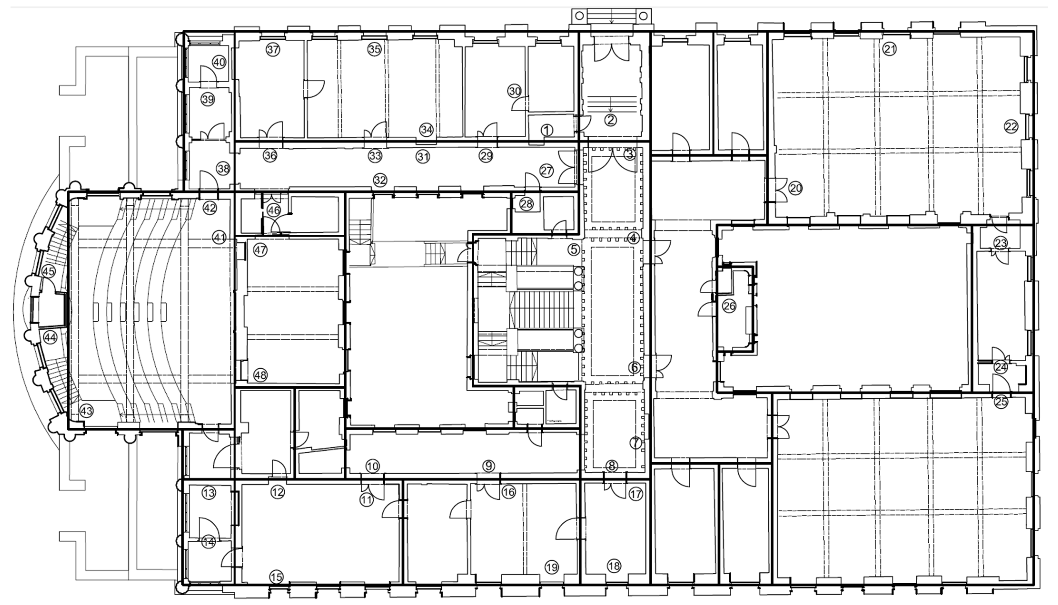
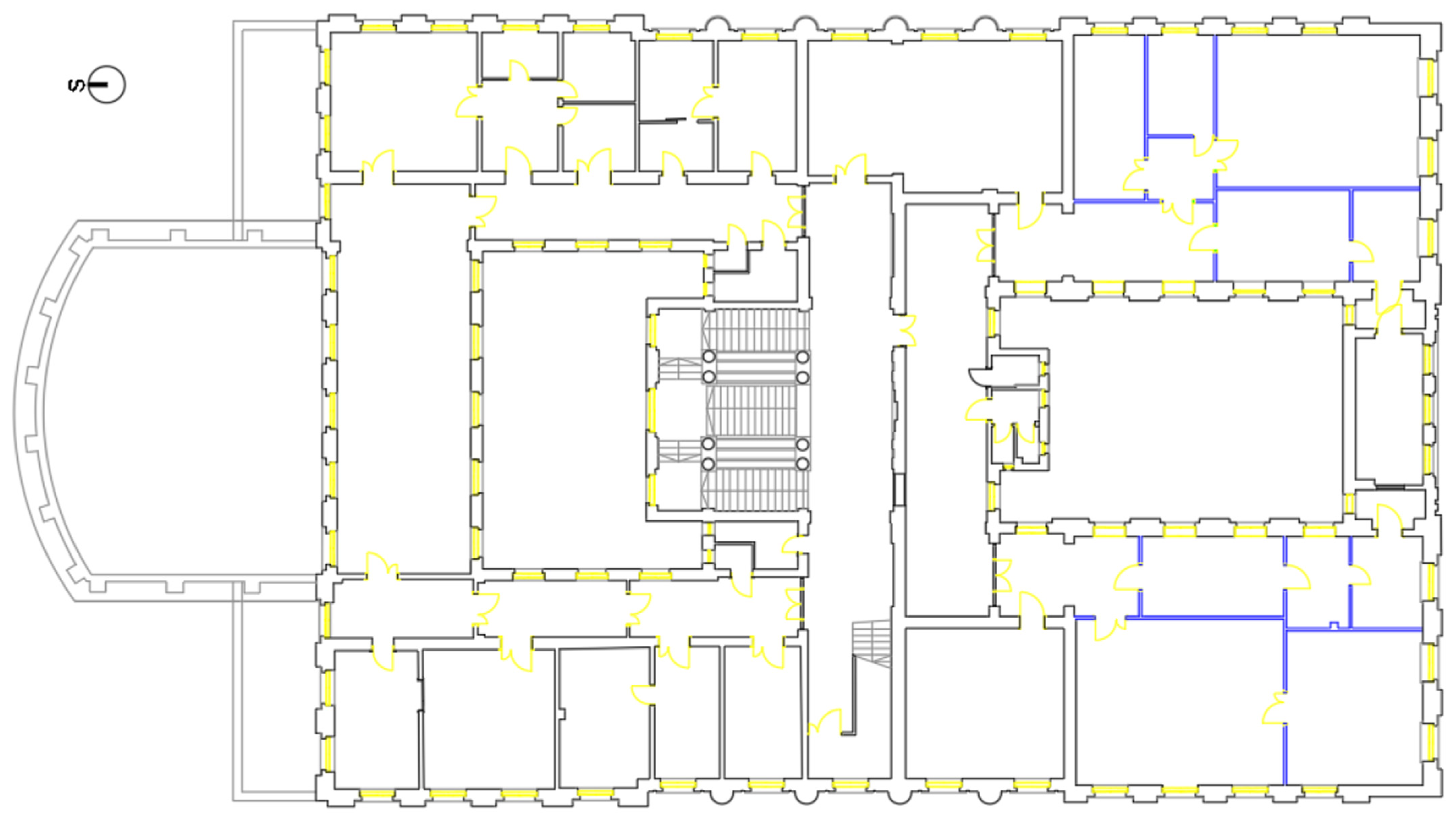
2.1. Architectural Background
- The removal of the traditional gabled wooden roof above the central staircase and the addition of a new floor (currently mostly occupied by a library) with the flat roof above.
- The partial rearrangement of the attic for office and laboratory use, with the raising of part of the parapet wall along the southern atrium to allow for the addition of windows and changes in the roof’s geometry.
- The installation of numerous skylights, especially on the roof above the southern facade, where parts of the roof feature a series of windows installed in improvised dormer structures.
- The installation of mechanical ventilation systems for various laboratories (separate units and sections) on the flat roof above the staircase section, and their modernization over time.
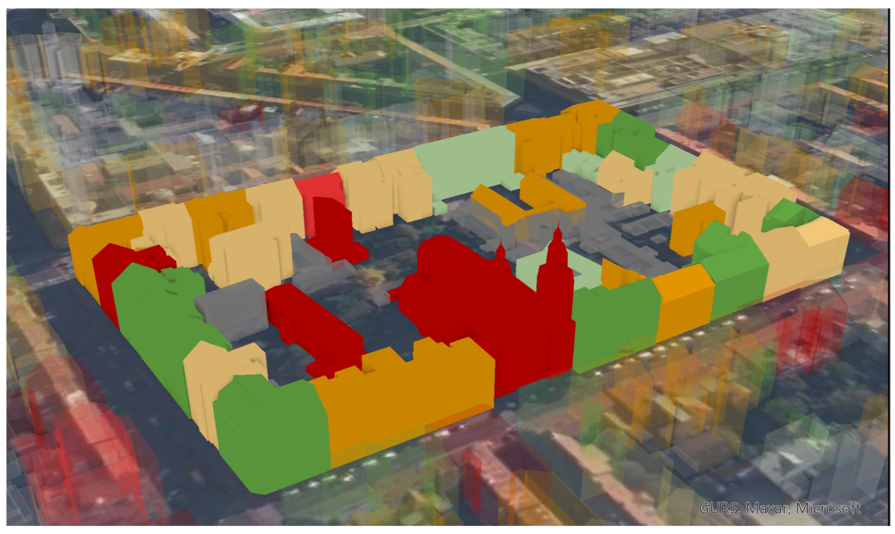
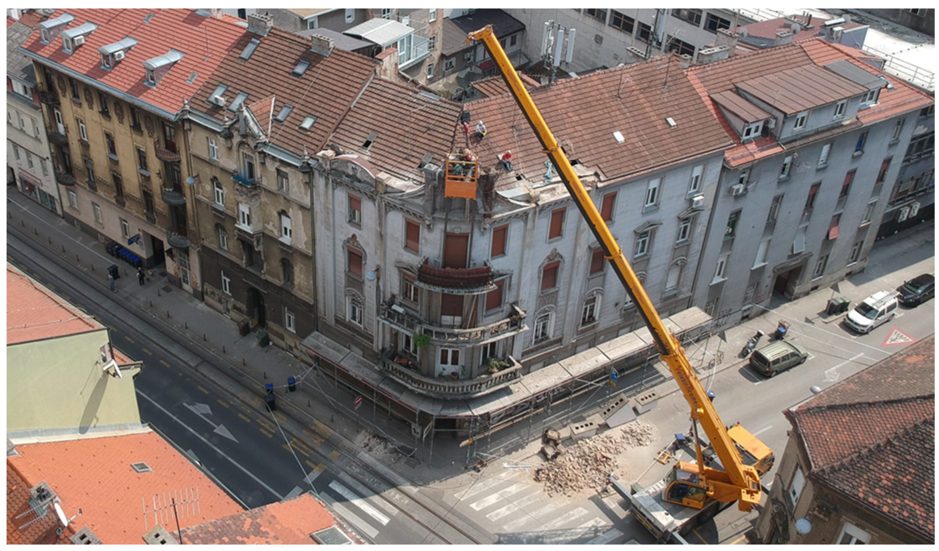
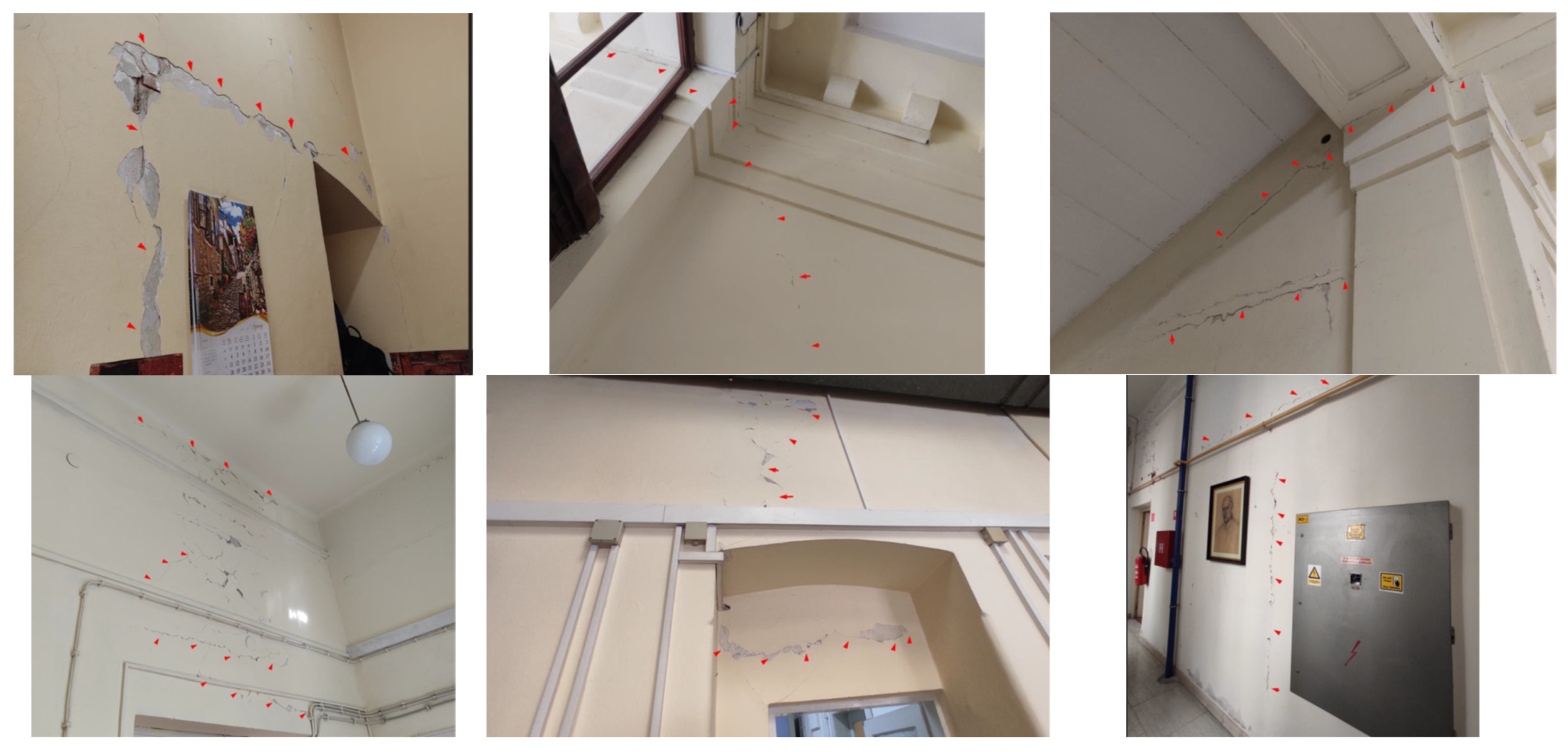
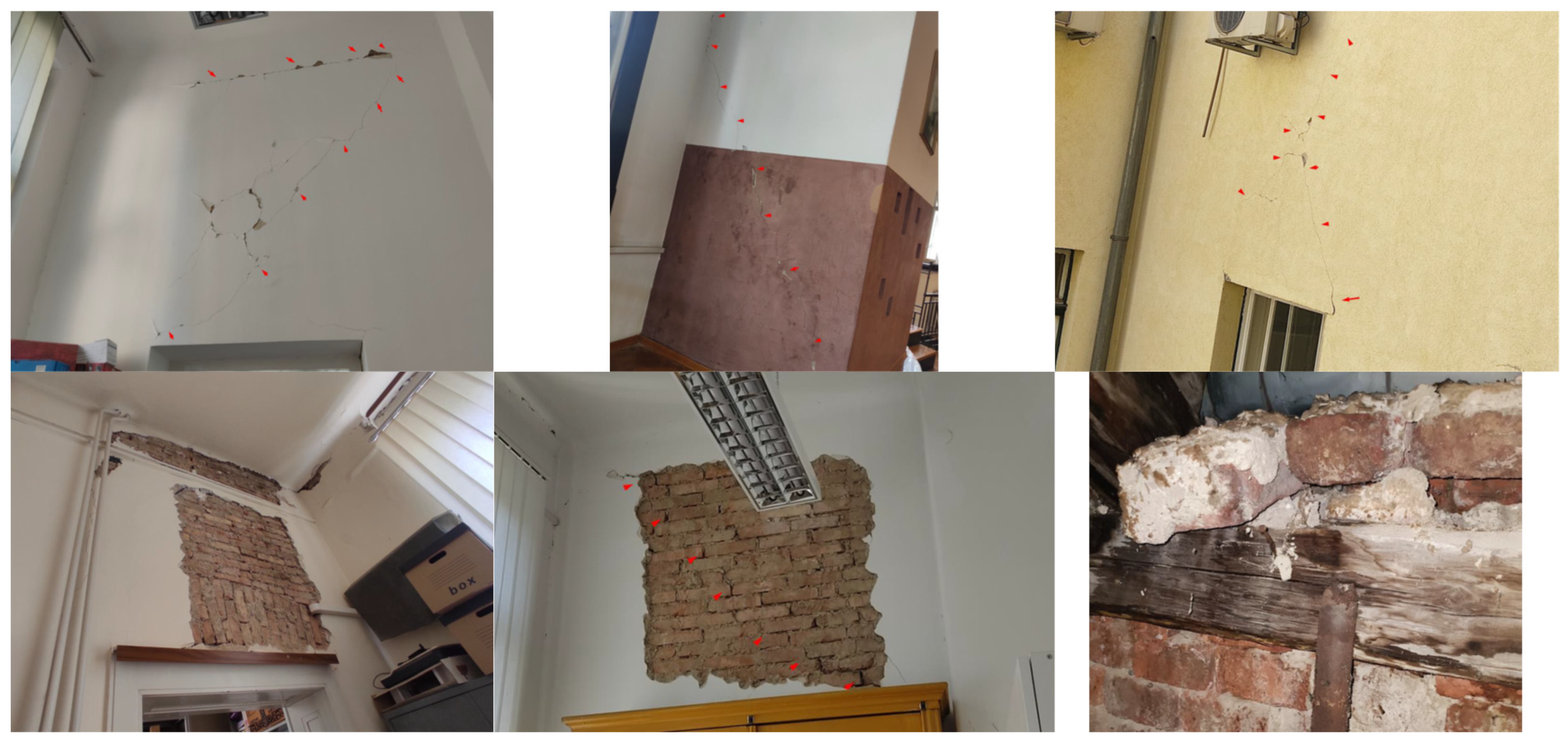
2.2. Rapid Post-Earthquake Assessment and Preliminary Analysis of the Existing Structure
3. Architectural and Structural Investigation
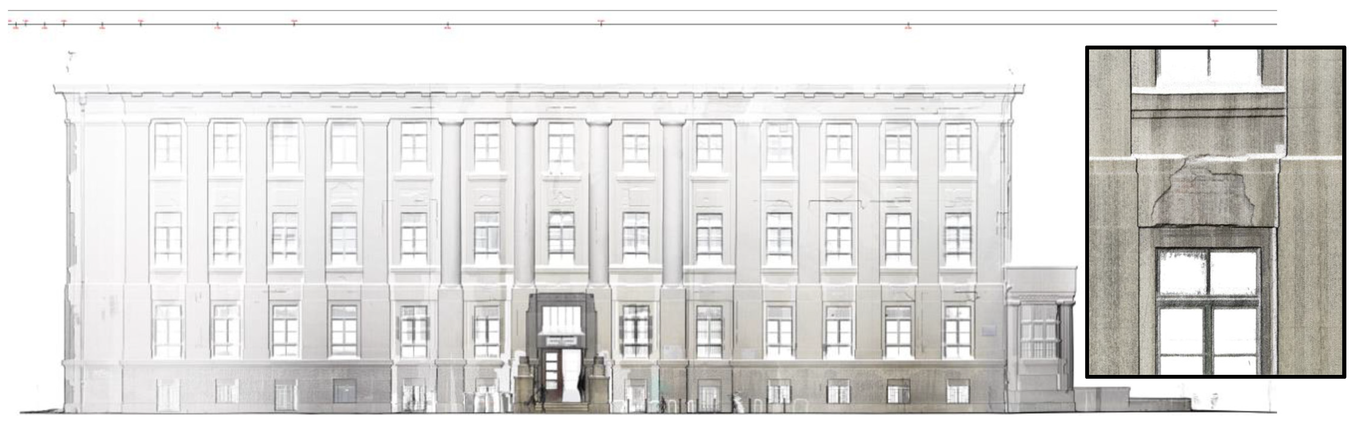
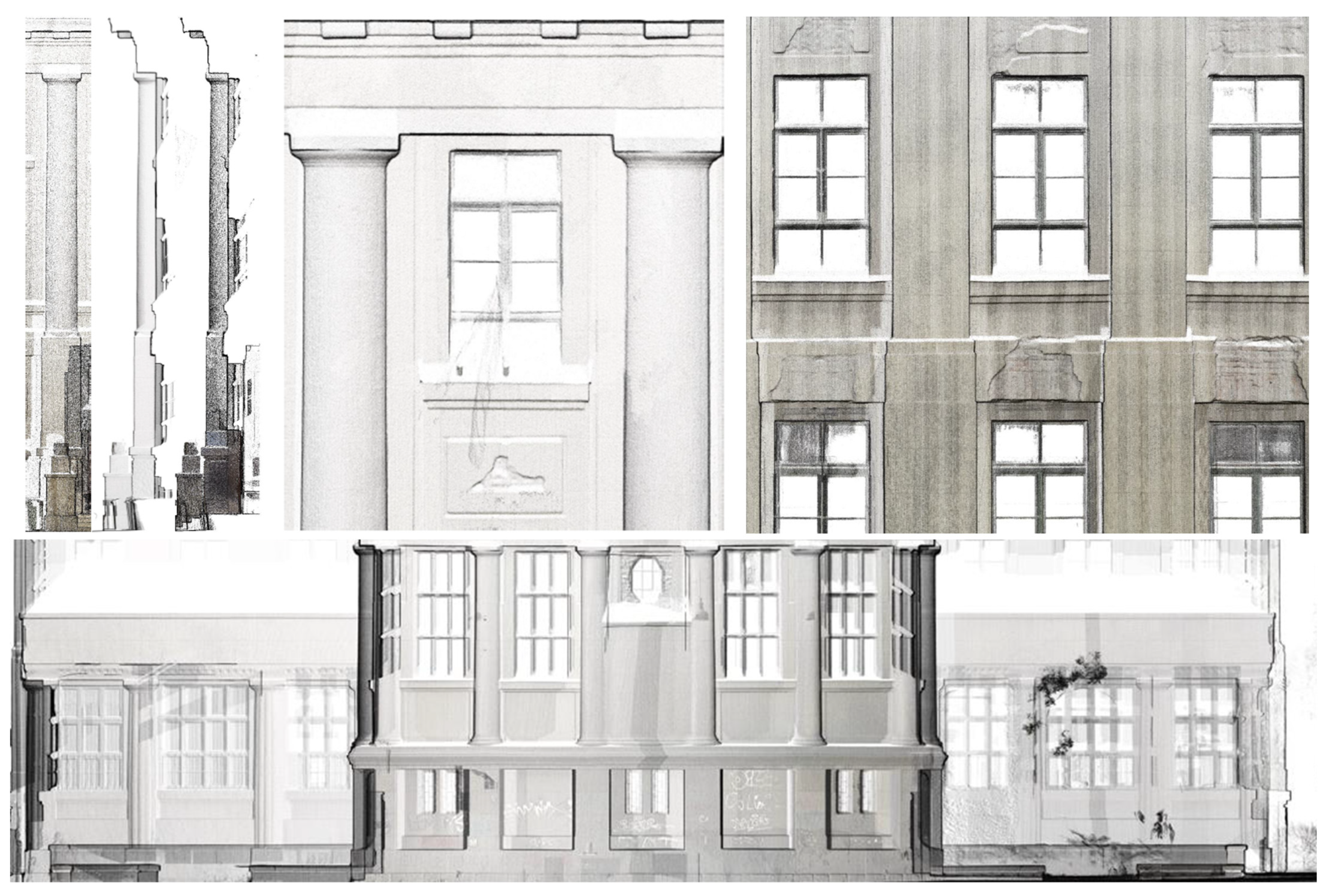
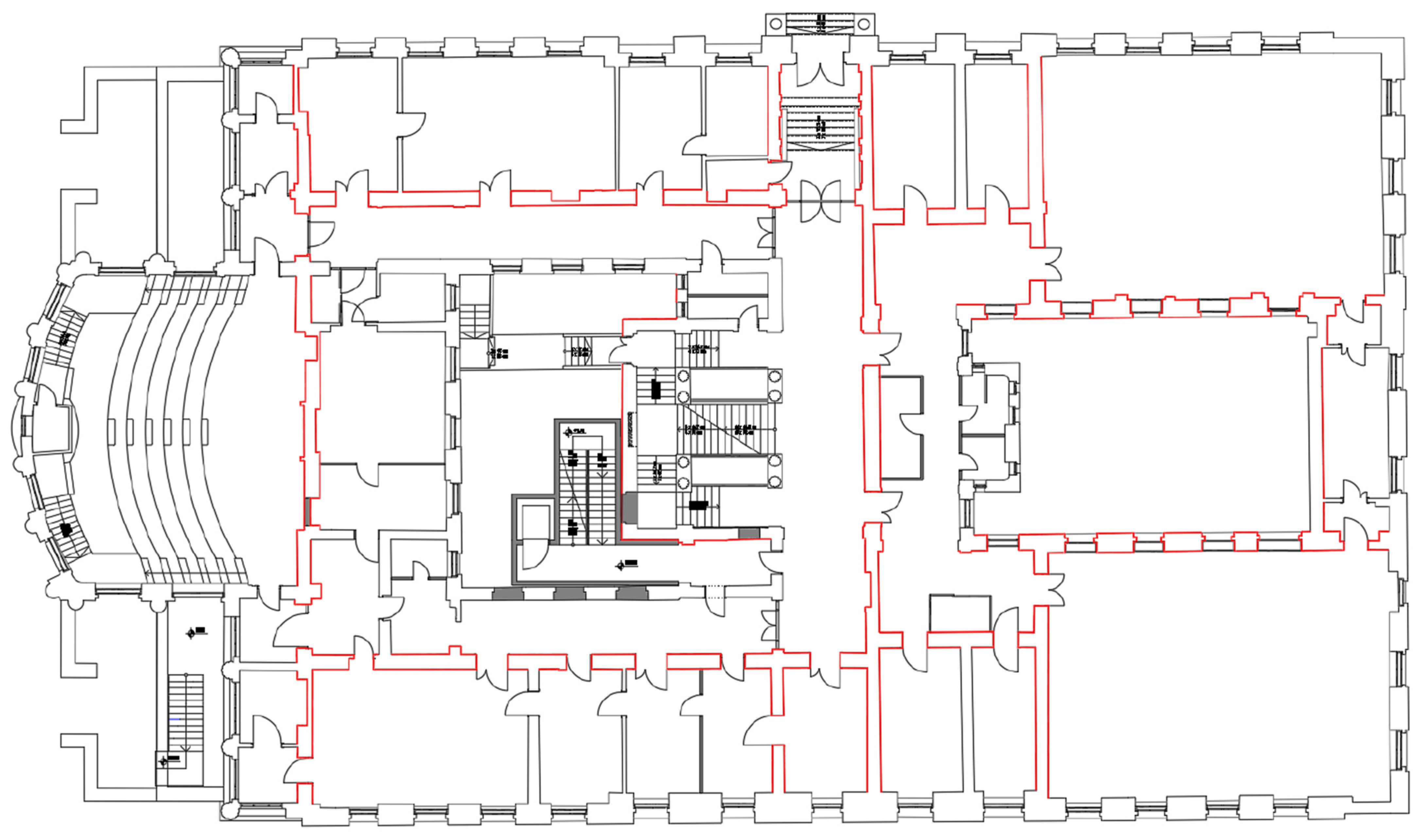
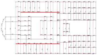
3.1. Architectural Survey
3.2. Material Investigation Work
- Exploratory drilling of foundations to determine the depth and dimensions of the foundation footing (three testing locations).
- Testing of the compressive strength of concrete (nine testing locations).
- Manual opening of the ceiling structure (one testing location).
- Manual opening of beams and columns to determine the layout, quantity, diameter, and condition of the reinforcement in RC parts of the building (one testing location).
- Determination of the thickness and type of attic floor (drilling through the floor structure using a diamond crown with water) (one testing location).
- Determination of the type of lintels through manual opening and drilling and identification of the position, type, quantity, and condition of embedded reinforcement (one testing location).
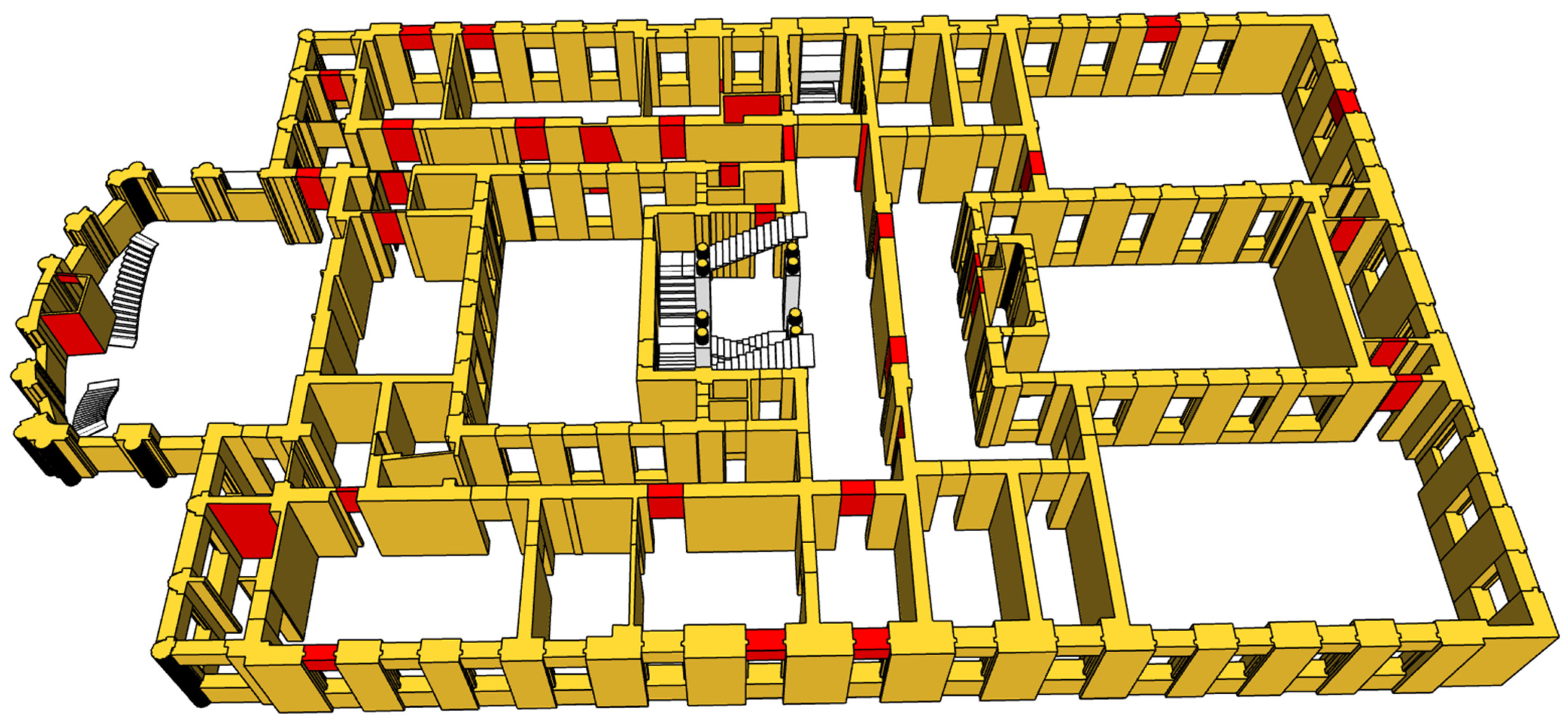
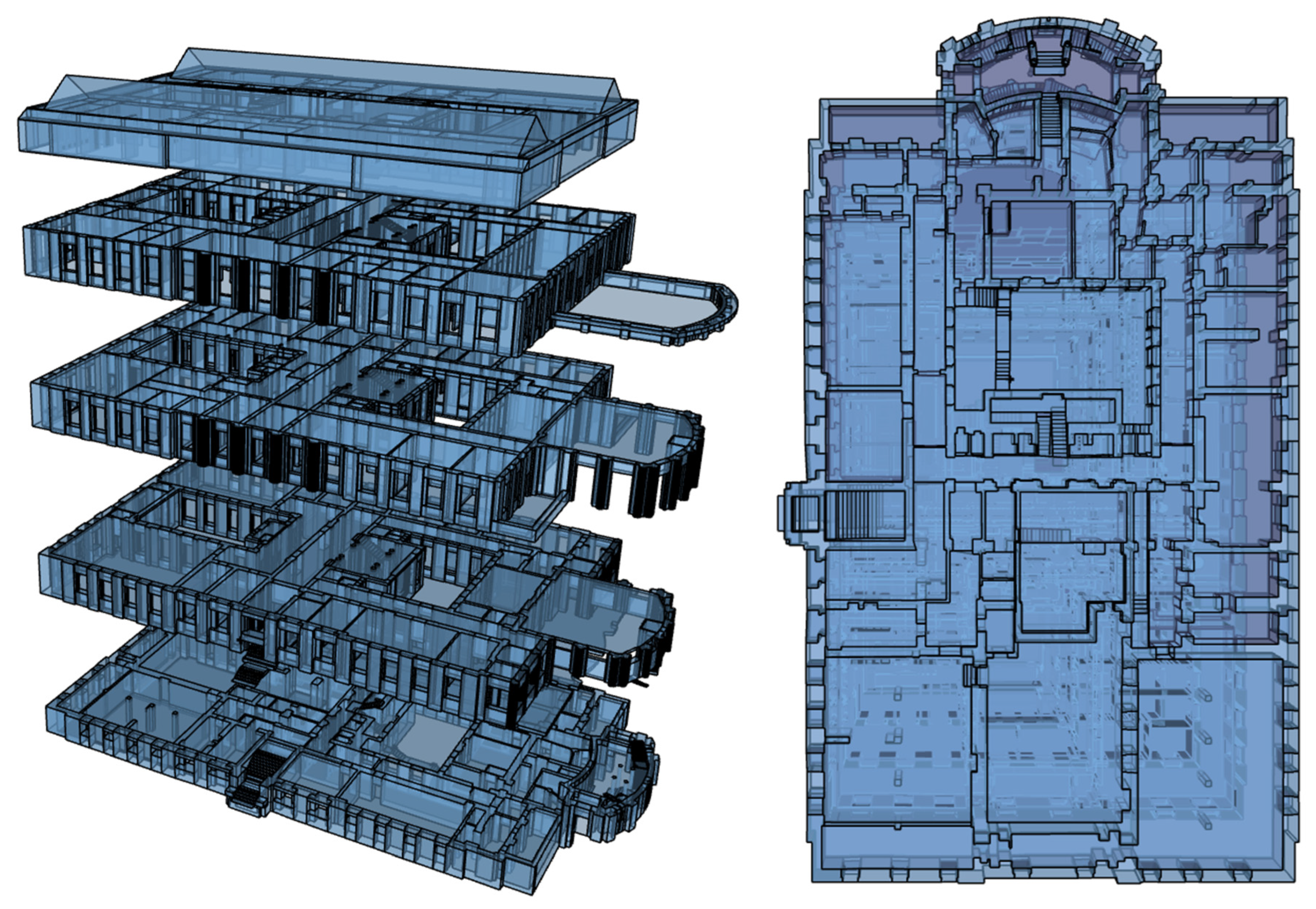
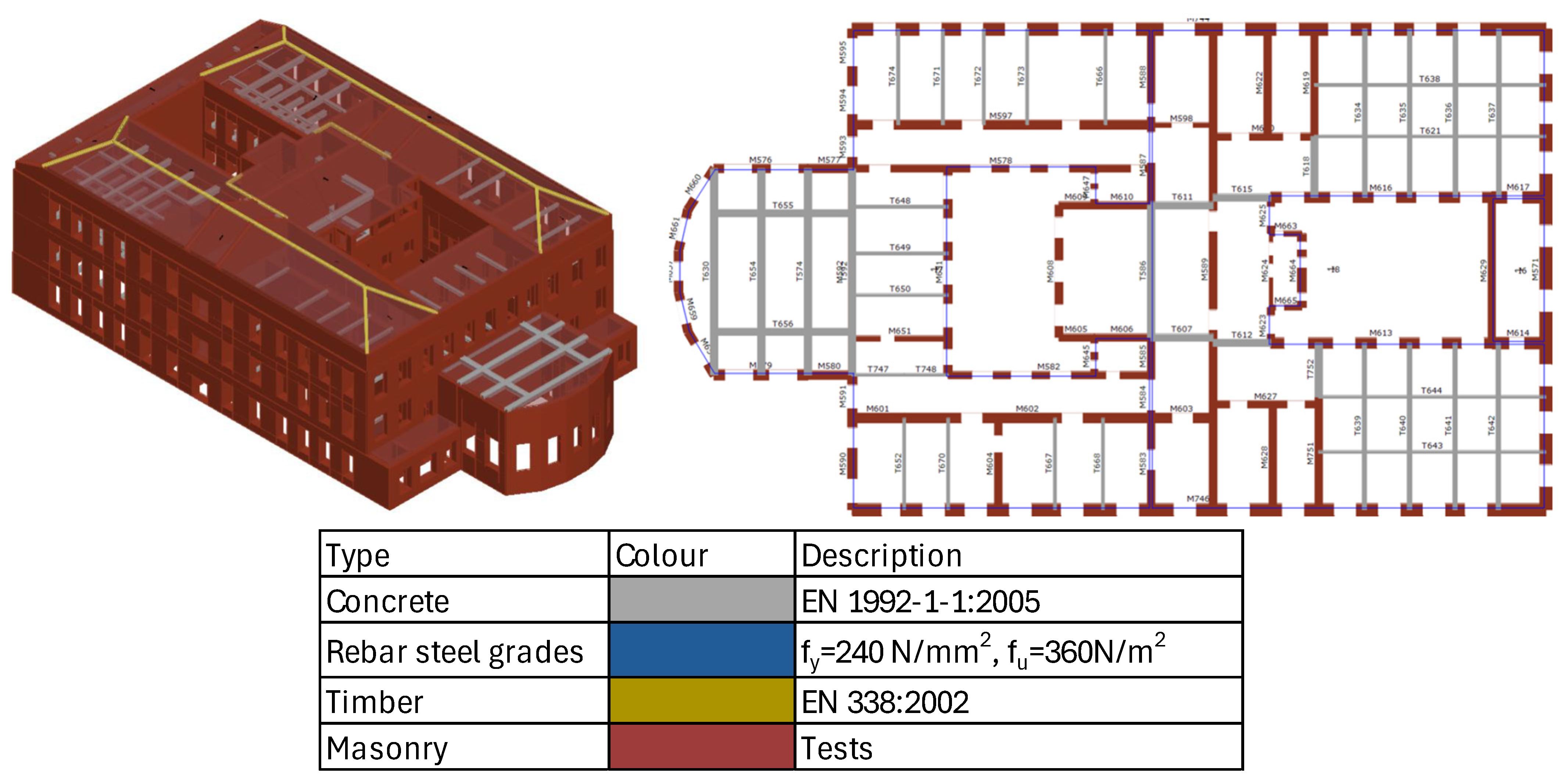
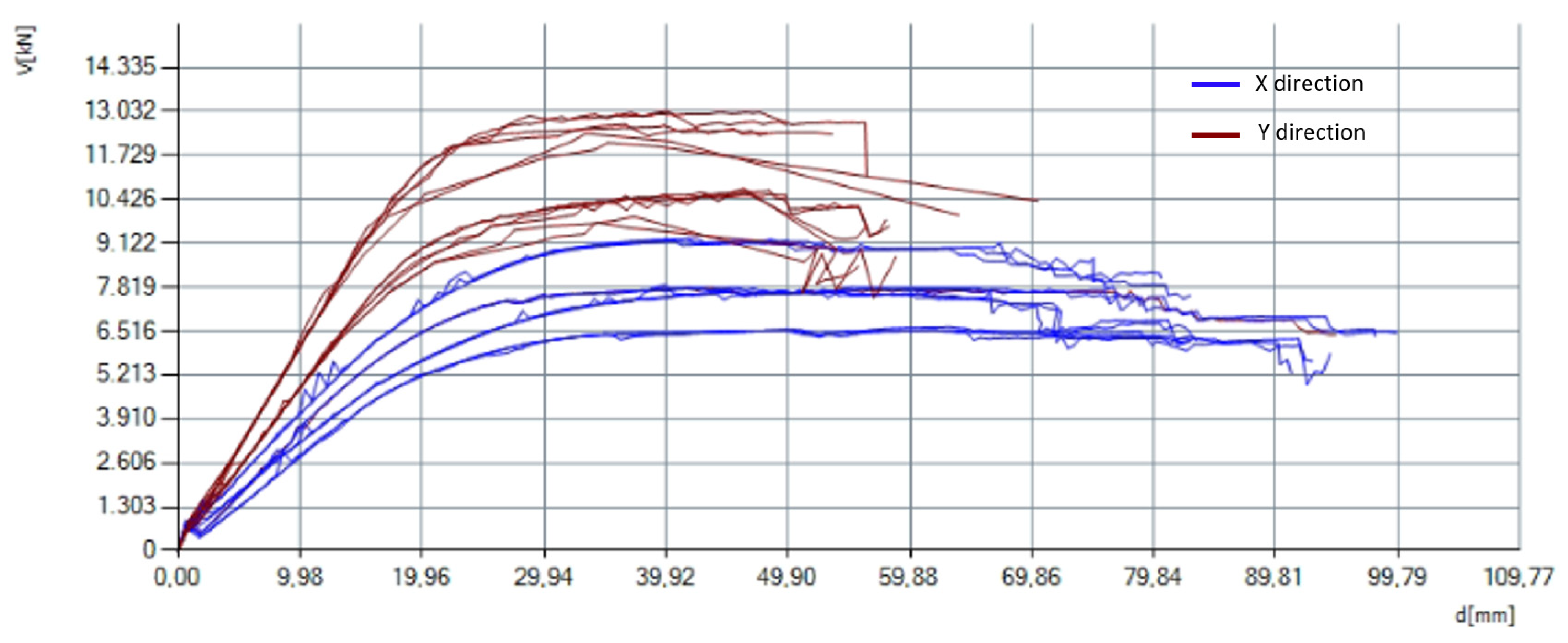
4. Numerical Modeling
4.1. Modeling of Existing Condition
4.2. Seismic Strengthening
5. Conclusions
Author Contributions
Funding
Data Availability Statement
Conflicts of Interest
References
- Stepinac, M.; Lourenço, P.B.; Atalić, J.; Kišiček, T.; Uroš, M.; Baniček, M.; Novak, M.Š. Damage classification of residential buildings in historical downtown after the ML5.5 earthquake in Zagreb, Croatia in 2020. Int. J. Disaster Risk Reduct. 2021, 56, 102140. [Google Scholar] [CrossRef]
- Bilgin, H.; Shkodrani, N.; Hysenlliu, M.; Ozmen, H.B.; Isik, E.; Harirchian, E. Damage and performance evaluation of masonry buildings constructed in 1970s during the 2019 Albania earthquakes. Eng. Fail. Anal. 2022, 131, 105824. [Google Scholar] [CrossRef]
- Vlachakis, G.; Vlachaki, E.; Lourenço, P.B. Learning from failure: Damage and failure of masonry structures, after the 2017 Lesvos earthquake (Greece). Eng. Fail. Anal. 2020, 117, 104803. [Google Scholar] [CrossRef]
- Dogan, G.; Ecemis, A.S.; Korkmaz, S.Z.; Arslan, M.H.; Korkmaz, H.H. Buildings Damages after Elazığ, Turkey Earthquake on January 24, 2020. Nat. Hazards 2021, 109, 161–200. [Google Scholar] [CrossRef]
- Günaydin, M.; Atmaca, B.; Demir, S.; Altunişik, A.C.; Hüsem, M.; Adanur, S.; Ateş, Ş.; Angin, Z. Seismic damage assessment of masonry buildings in Elazığ and Malatya following the 2020 Elazığ-Sivrice earthquake, Turkey. Bull. Earthq. Eng. 2021, 19, 2421–2456. [Google Scholar] [CrossRef]
- Kahya, V.; Genç, A.F.; Sunca, F.; Roudane, B.; Altunişik, A.C.; Yilmaz, S.; Günaydin, M.; Dok, G.; Kirtel, O.; Demir, A.; et al. Evaluation of earthquake-related damages on masonry structures due to the 6 February 2023 Kahramanmaraş-Türkiye earthquakes: A case study for Hatay Governorship Building. Eng. Fail. Anal. 2024, 156, 107855. [Google Scholar] [CrossRef]
- Işık, E.; Bilgin, H.; Avcil, F.; İzol, R.; Arkan, E.; Büyüksaraç, A.; Harirchian, E.; Hysenlliu, M. Seismic Performances of Masonry Educational Buildings during the 2023 Türkiye (Kahramanmaraş) Earthquakes. GeoHazards 2024, 5, 700–731. [Google Scholar] [CrossRef]
- Hafner, I.; Lazarević, D.; Kišiček, T.; Stepinac, M. Post-Earthquake Assessment of a Historical Masonry Building after the Zagreb Earthquake–Case Study. Buildings 2022, 12, 323. [Google Scholar] [CrossRef]
- Salaman, A.; Stepinac, M.; Matorić, I.; Klasić, M. Post-Earthquake Condition Assessment and Seismic Upgrading Strategies for a Heritage-Protected School in Petrinja, Croatia. Buildings 2022, 12, 2263. [Google Scholar] [CrossRef]
- Uroš, M.; Šavor Novak, M.; Atalić, J.; Sigmund, Z.; Baniček, M.; Demšić, M.; Hak, S. Post-earthquake damage assessment of buildings—Procedure for conducting building inspections. Gradjevinar 2020, 72, 1089–1115. [Google Scholar] [CrossRef]
- World Bank Report: Croatia December 2020 Earthquake—Rapid Damage and Needs Assessment; Government of Croatia: Zagreb, Croatia, 2021.
- World Bank Report: Croatia Earthquake—Rapid Damage and Needs Assessment; Government of Croatia: Zagreb, Croatia, 2020.
- Law on the Reconstruction of Earthquake-Damaged Buildings in the City of Zagreb, Krapina-Zagorje County and Zagreb County (NN 102/2020). Available online: https://narodne-novine.nn.hr/clanci/sluzbeni/2020_09_102_1915.html (accessed on 12 March 2022).
- Piccolo, A.P.; Longobardi, G.; Formisano, A. Seismic Vulnerability and Consolidation by FRP/FRCM Systems of a Masonry School Building in the District of Naples. Buildings 2022, 12, 2040. [Google Scholar] [CrossRef]
- Hafner, I.; Kišiček, T.; Gams, M. Review of Methods for Seismic Strengthening of Masonry Piers and Walls. Buildings 2023, 13, 1524. [Google Scholar] [CrossRef]
- HRN EN1998:1; Design of Structures for Earthquake Resistance—Part 1: General Rules, Seismic Actions and Rules for Buildings. HZN: Zagreb, Croatia, 2009.
- Rezaee, S.R.S.; Soltani, M.; Nikooravesh, M. Cyclic in-plane behavior of unreinforced and confined masonry walls retrofitted by shotcrete: Experimental investigation. Eng. Struct. 2022, 264, 114432. [Google Scholar] [CrossRef]
- Law on Reconstruction of Earthquake-Damaged Buildings in the City of Zagreb, Krapina-Zagorje County, Zagreb County, Sisak-Moslavina County and Karlovac County (NN 102/2020, 10/21). Available online: https://www.zakon.hr/z/2656/Zakon-o-obnovi-zgrada-o%C5%A1te%C4%87enih-potresom-na-podru%C4%8Dju-Grada-Zagreba%2C-Krapinsko-zagorske-%C5%BEupanije%2C-Zagreba%C4%8Dke-%C5%BEupanije%2C-Sisa%C4%8Dko-moslava%C4%8Dke-%C5%BEupanije-i-Karlova%C4%8Dke-%C5%BEupani (accessed on 12 March 2022).
- Novak, M.S.; Uros, M.; Atalic, J.; Herak, M.; Demsic, M.; Banicek, M.; Lazarevic, D.; Bijelic, N.; Crnogorac, M.; Todoric, M. Zagreb earthquake of 22 March 2020—Preliminary report on seismologic aspects and damage to buildings. Gradjevinar 2020, 72, 843–867. [Google Scholar] [CrossRef]
- Bošnjak, B.; Pekas, N.; Stepinac, M. Seismic Upgrading of the Heritage-Protected Reinforced Concrete Warehouse in Rijeka, Croatia. Buildings 2024, 14, 2912. [Google Scholar] [CrossRef]
- S.T.A. DATA, 3Muri Program, Release 12.2. Available online: www.stadata.com (accessed on 25 May 2021).
- Comisión Sismológica Europea. Escala Macro Sísmica Europea EMS-98; Comisión Sismológica Europea: Brussels, Belgium, 1998; Volume 15. [Google Scholar]
- Autodesk AutoCAD, Official AutoCAD Software. Available online: https://www.autodesk.com/uk/products/autocad/overview?term=1-YEAR&tab=subscription (accessed on 3 March 2025).
- Autodesk ReCap Pro Software. Available online: https://www.autodesk.com/uk/products/recap/overview?us_oa=dotcom-us&us_si=846e7b34-220d-4d6f-9bfd-3008af30a538&us_st=recap&us_pt=RECAPPRODUCTS&term=1-YEAR&tab=subscription&plc=RECAP (accessed on 3 March 2025).
- ASTM C1531-16; Standard Test Methods for In Situ Measurement of Masonry Mortar Joint Shear Strength Index. ASTM Internationa: West Conshohocken, PA, USA, 2022.
- HRN EN 12390-3:2019; Hrvatski Normativni Dokument/HRN4You-Hrvatski Zavod za Norme. Available online: https://repozitorij.hzn.hr/norm/HRN+EN+12390-3%3A2019 (accessed on 3 March 2025).
- HRN EN 12390-7:2019; Ispr.1:2020/Hrvatski Normativni Dokument/HRN4You-Hrvatski Zavod za Norme. Available online: https://repozitorij.hzn.hr/norm/HRN+EN+12390-7%3A2019%2FIspr.1%3A2020 (accessed on 3 March 2025).
- HRN EN 12504-1:2019; Hrvatski Normativni Dokument/HRN4You-Hrvatski Zavod za Norme. Available online: https://repozitorij.hzn.hr/norm/HRN+EN+12504-1%3A2019 (accessed on 3 March 2025).
- 3muri User manual 12.2.1. Available online: www.stadata.com (accessed on 13 May 2021).
- Borri, A.; Corradi, M. The Failure of Masonry Walls by Disaggregation and the Masonry Quality Index. Heritage 2020, 3, 1162–1198. [Google Scholar] [CrossRef]
- Malomo, D.; Pulatsu, B. Discontinuum models for the structural and seismic assessment of unreinforced masonry structures: A critical appraisal. Structures 2024, 62, 106108. [Google Scholar] [CrossRef]
- Fajfar, P.; Fischinger, M. N2—A method for non-linear seismic analysis of regular buildings. In Proceedings of the 9th World Conference in Earthquake Engineering, Tokyo, Japan, 2–9 August 1998; pp. 111–116. [Google Scholar]
- Turnšek, V.; Čačovič, F. Some experimental results on the strength of brick masonry walls. In SIBMAC Proceedings, Proceedings of the Second International Brick Masonry Conference Held in Stoke-on-Trent, England, on 12–15 April 1970; British Ceramic Research Association: Stoke-on-Trent, UK, 1971; pp. 149–156. [Google Scholar]
- Tomaževič, M. Shear resistance of masonry walls and Eurocode 6: Shear versus tensile strength of masonry. Mater. Struct. 2009, 42, 889–907. [Google Scholar] [CrossRef]
- Ortega, J.; Vasconcelos, G.; Rodrigues, H.; Correia, M. Assessment of the influence of horizontal diaphragms on the seismic performance of vernacular buildings. Bull. Earthq. Eng. 2018, 16, 3871–3904. [Google Scholar] [CrossRef]
- Stepinac, M.; Lulić, L.; Damjanović, D.; Duvnjak, I.; Bartolac, M.; Lourenço, P.B. Experimental Evaluation of Unreinforced Brick Masonry Mechanical Properties by the Flat-Jack Method—An Extensive Campaign in Croatia. Int. J. Archit. Herit. 2023, 18, 691–708. [Google Scholar] [CrossRef]
- Lulić, L.; Stepinac, M.; Bartolac, M.; Lourenço, P.B. Review of the flat-jack method and lessons from extensive post-earthquake research campaign in Croatia. Constr. Build. Mater. 2023, 384, 131407. [Google Scholar] [CrossRef]
- Ghiassi, B.; Vermelfoort, A.T.; Lourenço, P.B. Chapter 7—Masonry mechanical properties. In Woodhead Publishing Series in Civil and Structural Engineering; Ghiassi, B., Vermelfoort, A.T., Lourenço, P.B., Eds.; Woodhead Publishing: Cambridge, UK, 2019; Chapter 7; pp. 239–261. [Google Scholar] [CrossRef]
- Acito, M.; Buzzetti, M.; Chesi, C.; Magrinelli, E.; Milani, G. Failures and damages of historical masonry structures induced by 2012 northern and 2016–17 central Italy seismic sequences: Critical issues and new perspectives towards seismic prevention. Eng. Fail. Anal. 2023, 149, 107257. [Google Scholar] [CrossRef]
- Giuliani, F.; De Falco, A.; Cutini, V. Unpacking seismic risk in Italian historic centres: A critical overview for disaster risk reduction. Int. J. Disaster Risk Reduct. 2021, 59, 102260. [Google Scholar] [CrossRef]
- Predari, G.; Stefanini, L.; Marinković, M.; Stepinac, M.; Brzev, S. Adriseismic Methodology for Expeditious Seismic Assessment of Unreinforced Masonry Buildings. Buildings 2023, 13, 344. [Google Scholar] [CrossRef]
- Vuoto, A.; Funari, M.F.; Karimzadeh, S.; Lourenço, P.B. Generative modelling of Monopteros and Tholos temples using existing data: The case study of Vesta temple in Tivoli. J. Cult. Herit. 2025, 71, 334–345. [Google Scholar] [CrossRef]


| Label | Legend | Description |
|---|---|---|
| U1 | Usable without limitations | |
| U2 | Usable with recommendations | |
| PN1 | Temporarily unusable—detailed inspection needed | |
| PN2 | Temporarily unusable—emergency interventions needed | |
| N1 | Unusable due to external impact | |
| N2 | Unusable due to damage |
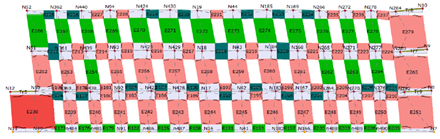
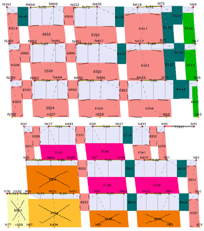
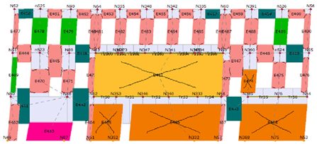
| R.C. | Masonry | ||
|---|---|---|---|
 | Undamaged |  | Undamaged |
 | Shear failure |  | Plasticity incipie |
 | Bending damage |  | Shear damage |
 | Bending failure |  | Incipient shear failure |
 | Compression failure |  | Shear failure |
 | Tension failure |  | Bending damage |
 | Shear failure |  | Incipient bending failure |
 | Wood |  | Bending failure |
 | Undamaged |  | Serious crisis |
 | Bending failure |  | Compression failure |
 | Compression failure |  | Tension failure |
 | Tension failure |  | Failure during elasitc phase |
 | Ineffective element | ||
 |  | ||
 |  | ||
 |  | ||
 |  | ||
Disclaimer/Publisher’s Note: The statements, opinions and data contained in all publications are solely those of the individual author(s) and contributor(s) and not of MDPI and/or the editor(s). MDPI and/or the editor(s) disclaim responsibility for any injury to people or property resulting from any ideas, methods, instructions or products referred to in the content. |
© 2025 by the authors. Licensee MDPI, Basel, Switzerland. This article is an open access article distributed under the terms and conditions of the Creative Commons Attribution (CC BY) license (https://creativecommons.org/licenses/by/4.0/).
Share and Cite
Arbutina, D.; Stepinac, M.; Pavković, K.; Čizmar, D. Architectural Study and Preliminary Seismic Assessment of a Typical Unreinforced Brick Masonry Building in Zagreb, Croatia. Buildings 2025, 15, 956. https://doi.org/10.3390/buildings15060956
Arbutina D, Stepinac M, Pavković K, Čizmar D. Architectural Study and Preliminary Seismic Assessment of a Typical Unreinforced Brick Masonry Building in Zagreb, Croatia. Buildings. 2025; 15(6):956. https://doi.org/10.3390/buildings15060956
Chicago/Turabian StyleArbutina, Dražen, Mislav Stepinac, Krunoslav Pavković, and Dean Čizmar. 2025. "Architectural Study and Preliminary Seismic Assessment of a Typical Unreinforced Brick Masonry Building in Zagreb, Croatia" Buildings 15, no. 6: 956. https://doi.org/10.3390/buildings15060956
APA StyleArbutina, D., Stepinac, M., Pavković, K., & Čizmar, D. (2025). Architectural Study and Preliminary Seismic Assessment of a Typical Unreinforced Brick Masonry Building in Zagreb, Croatia. Buildings, 15(6), 956. https://doi.org/10.3390/buildings15060956