Article

Dynamic Mechanical Properties and Deformation Mechanisms of Lightweight High-Strength TWIP Steel

1
Department of Materials Science and Engineering, College of Aerospace Science and Engineering, National University of Defense Technology, Changsha 410073, China
2
State Key Laboratory for Tunnel Engineering, China University of Mining and Technology (Beijing), Beijing 100083, China
3
Institute of Powder Metallurgy and Advanced Ceramics, College of Materials Science and Engineering, University of Science and Technology Beijing, Beijing 100083, China
*
Author to whom correspondence should be addressed.
Buildings 2025, 15(6), 897; https://doi.org/10.3390/buildings15060897
Submission received: 19 February 2025 / Revised: 3 March 2025 / Accepted: 10 March 2025 / Published: 13 March 2025

Abstract

This study developed a twinning-induced plasticity (TWIP) steel characterized by lightweight, high strength, and high toughness. Tensile tests were conducted at strain rates ranging from 10−4 to 6500 s−1 using a universal testing machine and a Hopkinson bar to evaluate the material’s mechanical properties. A Johnson–Cook (J-C) constitutive model was developed based on the mechanical performance data for high-strain behavior. X-ray diffraction (XRD), scanning electron microscopy (SEM), and electron backscatter diffraction (EBSD) were employed to analyze the microstructural evolution and fracture mechanisms of tensile specimens. The results show that the TWIP steel exhibits positive strain rate sensitivity (PSRS) under both quasi-static and dynamic strain rates. At high strain rates, the yield strength increased from 1133.0 MPa to 1430.6 MPa, and the tensile strength rose from 1494.3 MPa to 1640.34 MPa. The J-C model fits well at strain rates of 1000 s−1 and 3000 s−1, but fitting errors increase at higher strain rates due to the competition between thermal softening and strain hardening. XRD results reveal no significant phase transformation occurred during deformation, with twinning being the dominant mechanism. As the strain rate increased, deformation twins appeared in the material’s microstructure, inducing plastic deformation during tensile testing. The twin volume fraction increases progressively with the strain rate. At high strain rates, secondary twins emerge and intersect with primary twins, refining the grains through mutual interaction. The TWIP effect enhances the material’s mechanical performance by improving its strength and ductility while maintaining its lightweight nature.

1. Introduction

With the rapid development of modern destructive weaponry in recent years, armored equipment and protective facilities have imposed increasingly stringent performance and lightweight strategic requirements on protective materials. Consequently, the development of steel materials faces both new challenges and opportunities. Based on traditional high-Mn steels, researchers have incorporated elements such as Al and Si to enhance the properties of the steels through twinning-induced plasticity [1,2], leading to the development of Twinning-Induced Plasticity steel. The first generation of TWIP steel primarily consisted of Fe, Mn, Al, and Si elements. However, the relevant research revealed that its tensile strength was relatively low. Although the addition of a significant amount of Si reduced the stacking fault energy, it also led to the formation of surface oxides, which adversely affected subsequent coating and processing operations [3]. The second generation of Fe-Mn-C TWIP steel eliminated Si and incorporated a higher content of C, resulting in a significant improvement in strength. However, this composition led to a notable reduction in plasticity and processability. It was not until the third generation of TWIP steel, which introduced a controlled amount of Al based on the second-generation composition, that a balance between strength and plasticity was achieved. The addition of Al enhanced tensile strength while suppressing martensitic transformation. Research has demonstrated that TWIP steel, as a second-generation advanced high-strength steel, exhibits not only high strength and high elongation but also exceptional energy absorption capacity [4]. Its product of strength and elongation (PSE.) which is calculated by multiplying the tensile strength and the fracture elongation, exceeds 50,000 MPa%, more than twice that of traditional high-strength steels. Additionally, TWIP steel is characterized by low cost and lightweight properties. In TWIP steel, the creation of deformation twins during deformation hinders the movement of dislocations [5] and decreases their mean free path. This allows the steel to retain its high work-hardening ability and dynamic energy absorption properties, even when subjected to high strain rates. These properties make TWIP steel advantageous for applications such as shockwave absorption and resistance to fragment impact. Currently, it is widely used in the production of automotive crash-resistant components, including bumpers [6] and crash boxes [7]. The occurrence of the TWIP effect in TWIP steel is highly dependent on the material’s intrinsic properties, particularly the stacking fault energy (SFE). Research by Fajardo et al. [8] has shown that when the stacking fault energy falls within the range of 20 to 60 mJ/m2, the deformation mechanism of the material is dominated by twinning, thereby inducing the TWIP effect. When the stacking fault energy is less than 15 mJ/m2, dislocation slip and deformation-induced martensitic transformation become the primary deformation mechanisms, leading to plasticity through the TRIP effect. Conversely, when the stacking fault energy exceeds 60 mJ/m2, dislocation slip predominates [9,10,11]. Generally, it is believed that a lower stacking fault energy facilitates the formation of deformation twins, thereby promoting plastic deformation in the material.
However, the stacking fault energy (SFE) of TWIP steel is influenced by the types and contents of alloying elements, with various elements having different effects on the SFE. The expansion of the austenite region can be achieved by increasing the Mn content, resulting in a large volume of stable austenite, which can partially inhibit the SFE and promote the twinning mechanism. Studies indicate that the stability of the material greatly improves when its main content is between 15% and 30% [12]. Additionally, research indicates that adding 1 wt.% Al to Fe-Mn-Al-C steel can reduce the material’s weight by 1.3% [13], while simultaneously enhancing its oxidation resistance and wear resistance. Although Al increases the SFE, exceeding 3–4 wt.% Al can lead to the precipitation of intermetallic compounds, resulting in brittle fractures and hindering the activation of the TWIP effect. Also, the addition of Al in TWIP steels suppresses dynamic strain aging (DSA) and promotes the transition from negative to positive strain rate sensitivity [14]. Carbon (C) exists in TWIP steel as interstitial atoms, contributing to solid solution strengthening and expanding the austenite phase region. It also increases the stacking fault energy (SFE), thereby suppressing the formation of martensite. With an increase in carbon content, the material’s plasticity tends to decrease [15,16,17]. The addition of nickel (Ni) promotes the precipitation of carbonitrides, thereby enhancing matrix strengthen [18]. The TWIP effect can be activated by carefully regulating its content, leading to a significant improvement in the material’s performance [19]. The development of high-performance TWIP steels that combine low density with excellent properties has been achieved by researchers using a multi-principal element design approach. Y.F. An et al. [13] developed a Fe-28Mn-11Al-1C-5Ni (wt.%) TWIP steel, forming a dual-precipitation system of κ-carbides and B2 precipitates, resulting in a significant increase in the material’s hardening capability. This provides a reference for the design of austenitic lightweight steels with dual-nanoprecipitate. Sihan Lu et al. [20] designed a novel high-nitrogen TWIP steel that effectively balances low stacking fault energy (SFE) and austenite stability, achieving a breakthrough reduction in SFE to as low as 16.52 mJ/m2. The material’s strength and plasticity are both improved by the formation of nano-twins. Xinchang Feng et al. [21] performed high-speed tensile tests on Fe-Mn-Al-Si-C steels at strain rates ranging from 5 to 500 s−1. They found that as the strain rate increased, the nano-twins generated during deformation not only hindered dislocation motion but also altered grain orientation, synergistically controlling the changes in material strength and plasticity. At a strain rate of 500 s−1, the material was capable of attaining a tensile strength of 1.2 GPa. Qiao Ke et al. [22] investigated the hot deformation behavior and dynamic recrystallization mechanisms of TWIP steel, which provides a theoretical foundation for the processing techniques of structural materials in construction.
TWIP steel’s weldability is directly linked to its application effectiveness in automotive manufacturing and engineering structures in welding technology. The related research has shown that TWIP steel is prone to issues such as softening of the heat-affected zone (HAZ), grain coarsening, and degradation of mechanical properties in welded joints during welding. Advanced welding techniques have been employed to improve the welding quality of TWIP steel, such as laser welding and gas tungsten arc welding (GTAW). However, further research is necessary to comprehend the microstructural evolution and changes in mechanical properties during welding [23,24]. In dissimilar material welding, significant attention has been paid to the integrity of interfaces and performance degradation [25]. Through welding thermal simulation technology, researchers can gain deeper insights into the microstructural and mechanical property evolution of high-Mn TWIP steel in the HAZ [26]. When it comes to seismic performance and dynamic loading, TWIP steel is a great option for seismic-resistant structural materials because of its energy dissipation capacity and deformation behavior under high strain rates. Research has demonstrated that even under high strain rates, TWIP steel maintains remarkable strength and ductility, with its twinning deformation mechanism being crucial under dynamic loading [27]. The exceptional hysteretic performance and energy absorption capacity of metallic energy dissipators based on TWIP steel present novel approaches to enhancing the seismic performance of building structures [28]. However, the hydrogen embrittlement sensitivity of TWIP steel limits its application in hydrogen environments. The high Mn content and austenitic structure make TWIP steel susceptible to hydrogen embrittlement, as the ingress of hydrogen atoms can significantly degrade its mechanical properties. By regulating grain size and distribution, the hydrogen embrittlement resistance of TWIP steel can be effectively improved [29]. Furthermore, new methods for evaluating hydrogen embrittlement in steels with low hydrogen diffusion coefficients offer new perspectives on TWIP steel research [29]. TWIP steels’ high Mn content makes them susceptible to localized corrosion in chloride environments. However, its corrosion resistance can be enhanced through microstructural regulation and heat treatment optimization. For example, studies on the corrosion behaviors of electron beam-welded thick TWIP steel plates have shown that the microstructural evolution of the welded joints has a significant impact on their corrosion resistance [30]. Additionally, the role of annealing processes in regulating the microstructure and corrosion resistance of TWIP steel has received widespread attention [31,32]. The preceding studies demonstrate that TWIP steel’s rapid development and extensive research in terms of improving seismic performance, optimizing lightweight design, improving impact resistance, enhancing corrosion resistance, and advancing welding technologies have significantly expanded its application potential in fields such as high-rise buildings, long-span bridges, marine engineering, seismic resistant structures, and green construction [33]. Furthermore, its exceptional dynamic energy absorption characteristics at high strain rates demonstrate its enormous potential in blast and impact protection applications, making it a promising candidate for advanced protective structures.
Although traditional TWIP steel has excellent mechanical properties, its high density poses a significant challenge for lightweighting applications. The incorporation of aluminum (Al) into TWIP steel represents a promising solution because it can significantly reduce structural weight while maintaining high strength and ductility. However, the deformation mechanisms of TWIP steel are highly sensitive to variations in elemental composition. Due to the complexity of the deformation mechanism and the adjustability of the material properties of TWIP steel, it is of great significance to study the mechanical properties and deformation mechanism of TWIP steel for its structural design and application [34].
In this study, the dynamic mechanical properties of low-density Fe-Mn-Al-Ni-C TWIP steel were investigated using a Hopkinson tension bar under various high strain rates, with a focus on the influence of strain rate on the material’s mechanical behavior. Based on the obtained mechanical performance data, the Johnson–Cook (J-C) constitutive model was employed to fit the material’s stress–strain response, and the corresponding constitutive parameters were determined. Furthermore, the fracture surfaces and microstructures of the specimens subjected to high strain rate tensile tests were characterized using scanning electron microscopy (SEM) and electron backscatter diffraction (EBSD). These analyses aimed to elucidate the deformation mechanisms and underlying patterns of the material under different strain rates. The findings provide valuable insights into the deformation behavior of TWIP steel and offer guidance for its application in the construction industry, particularly in scenarios requiring high strain rate performance and lightweight design.

2. Materials and Methods

2.1. Material

The Fe-Mn-Al-Ni-C TWIP steel utilized in the experiment was melted in a vacuum induction furnace and cast into ingots, with the chemical composition of the steel detailed in Table 1. The ingots were heated to 1200 °C in the induction furnace and held for 2 h, followed by hot rolling using a 450 hot rolling mill. The rolling process consisted of seven passes, reducing the thickness from 80 mm to 15 mm. The initial rolling temperature was controlled at 1000 ± 50 °C, and the final rolling temperature was maintained at 900 °C. After rolling, the material was air-cooled to room temperature. The density of the material was measured using a densitometer, obtaining a final density of ρ = 6.91   g / c m 3 .

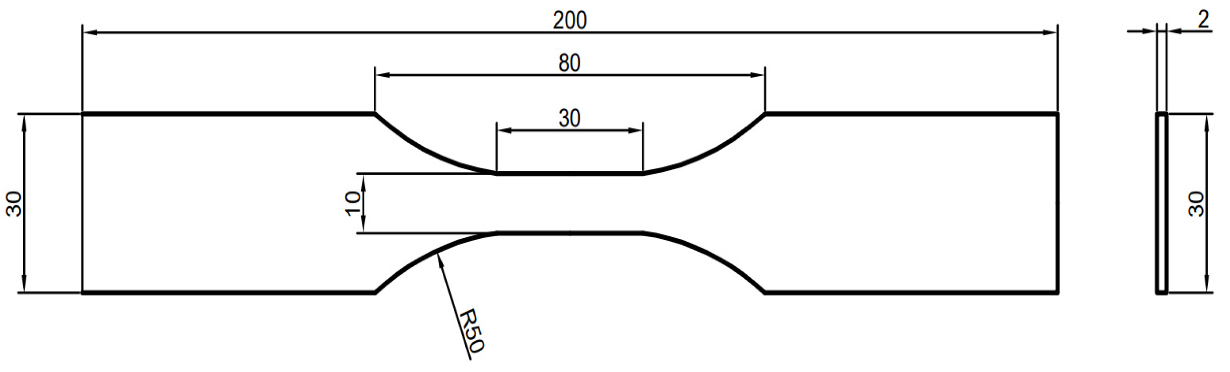
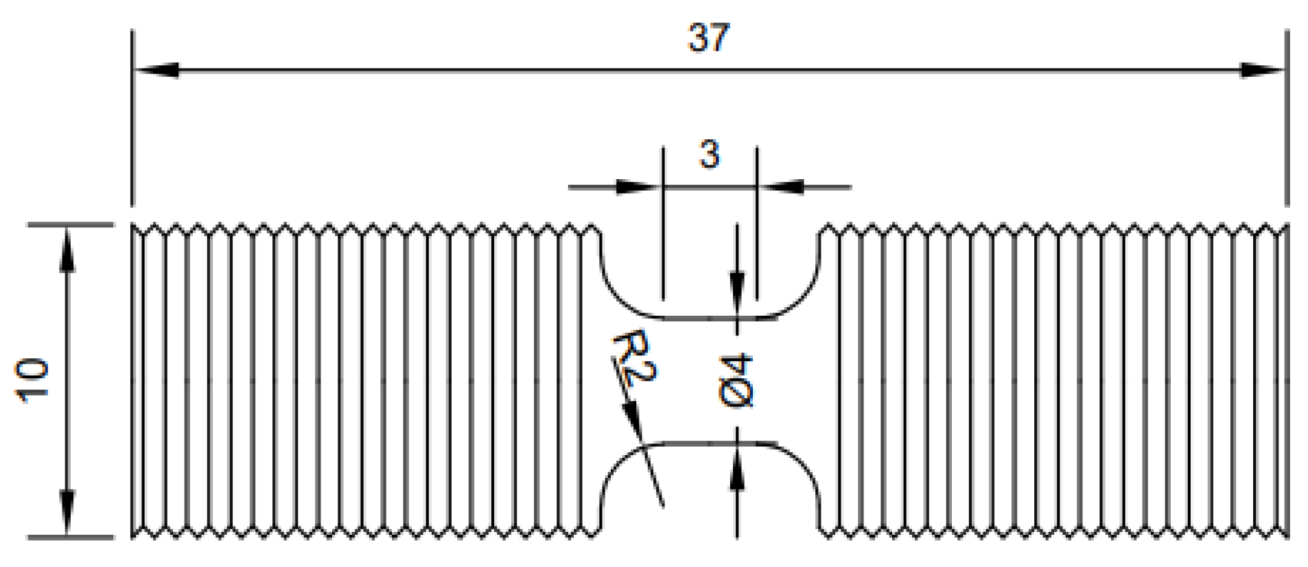
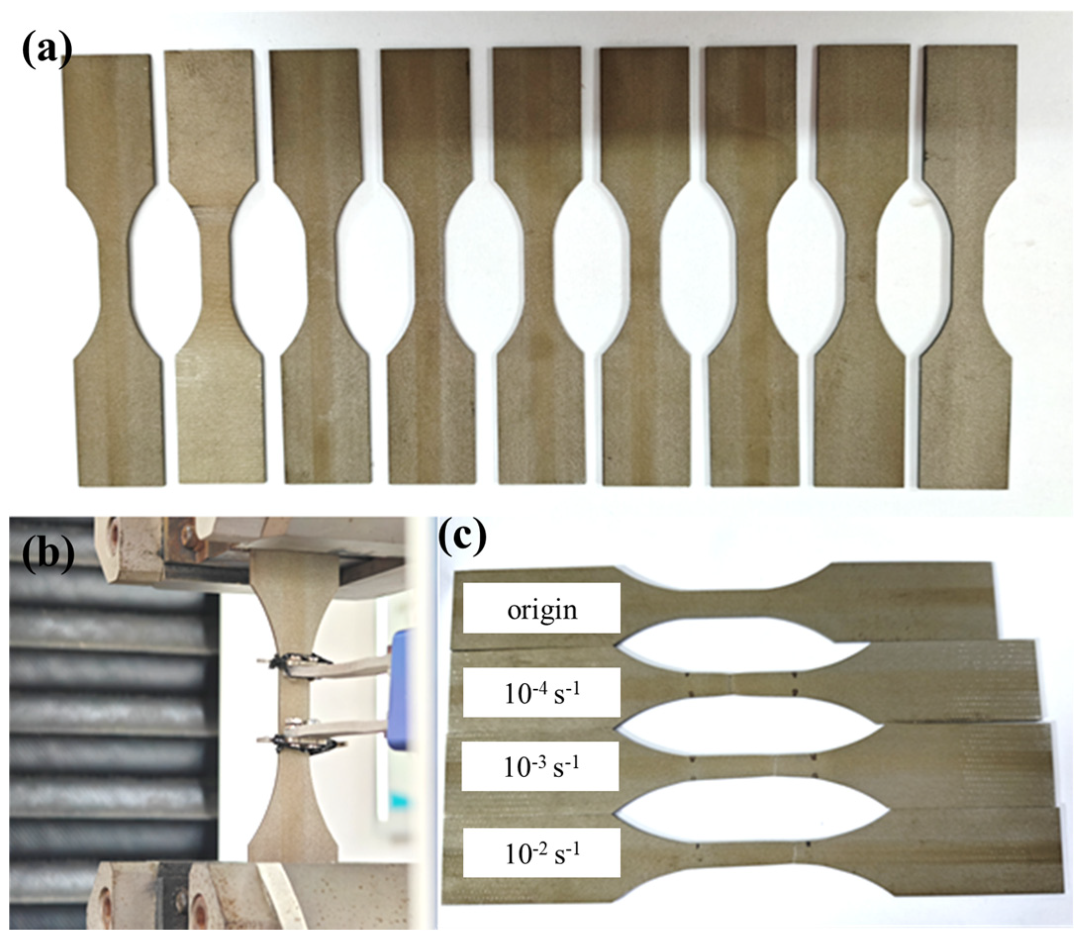
2.2. Experiment Method

According to the standard “Tensile Test of Metal Materials Part 1: Test method at room temperature” (GB/T 228.1-2010) [35], the plate dumbbell standard specimen used in the test fully considers the influence of the size effect to ensure the accuracy and reliability of the test results. The samples were processed by the electrical discharge cutting method with the dimension which is shown in Figure 1, and the rolling direction was taken as the sampling direction of the sample. The tensile tests of TWIP steel were carried out by a WDW-100 universal testing machine at three different controlled strain rates of 10−4 s−1, 10−3 s−1, and 10−2 s−1. Three tests were carried out at each strain rate to ensure the repeatability of the test.
The dynamic tensile sample was processed using the electrical discharge cutting method, with the sampling direction aligned parallel to the rolling direction. According to the standard entitled “High strain rate tensile tests for metallic materials-Part 1: elastic rod type systems” [36], the test adopted a round rod type sample with a total length of 37 mm, and the length of the standard distance segment was 3 mm. The standard thread of 15 mm is processed at the clamping end, and the sample size is shown in Figure 2.
The Split Hopkinson Tension Bar (SHTB) tests were carried out on a separated Hopkinson press-tension universal test setup of Tianjin Archimedes Industrial Science and Technology Co., Ltd in Tianjin China. Dynamic tensile mechanical properties testing of TWIP steel was carried out at the strain rate of 1000 s−1, 3000 s−1, 5000 s−1, and 6500 s−1, respectively. The tests were performed for three repeated trials under each strain rate to ensure that at least two valid and reliable results were obtained. After the experiment, the waveform data obtained were processed using ARCHIMEDES ALT1200 software. The two-wave method was applied to convert the data into stress–strain relationships so that the material’s fundamental mechanical properties were obtained. Based on these mechanical properties data, a dynamic constitutive model was established using the J-C formulation.
The block samples of 10 mm × 10 mm × 2 mm were processed near the fracture specimen of dynamic tensile by wire cutting, and the microstructure of the specimen was observed and analyzed by XRD, SEM, and EBSD. The XRD test samples were sanded with 400 #~3000 # SiC sandpaper until the direction of the surface scratches remained consistent for the preparation. The samples were cleaned with an anhydrous ethanol solution and dried with a hair dryer. The samples were polished with SiO2 polishing solution to achieve a scratch-free and smooth mirror surface, and then corroded with 4% ethanol nitrate solution for SEM observation and analysis. The samples for EBSD were prepared by polishing the samples with conventional metallographic 400#~2000# sandpaper and then vibration polishing after physical polishing.

3. Results and Discussion

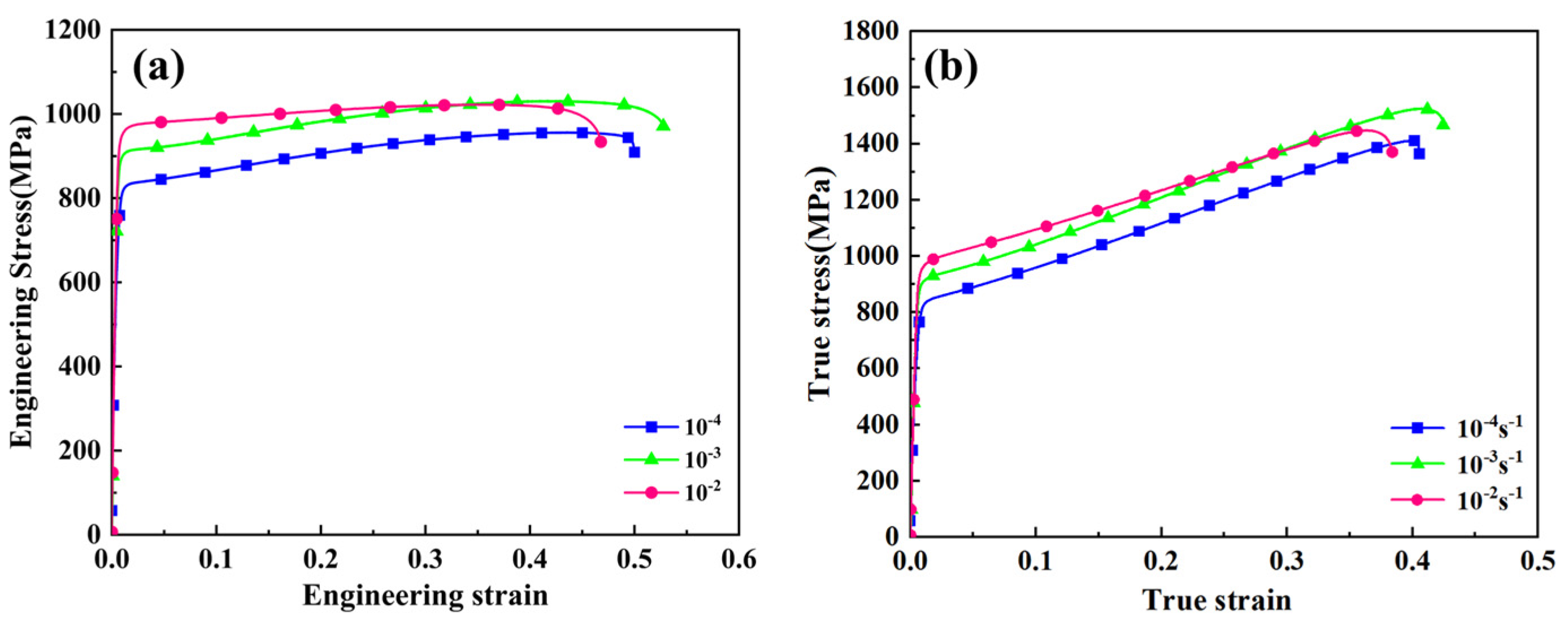
3.1. Quasi-Static Mechanical Properties

To evaluate the quasi-static mechanical properties of the new TWIP steel, tensile tests were conducted at strain rates of 10−2 s−1, 10−3 s−1, and 10−4 s−1. Figure 3 shows the specimen dimensions and the arrangement of the extensometer during the tests. From the macroscopic image of the specimen after fracture (Figure 3c), it is evident that the material undergoes significant elongation, with no noticeable necking observed at any of the strain rates, indicating good toughness under specified strain rate. The force–displacement curves were converted into stress–strain curves, as shown in Figure 4, which demonstrates the engineering stress–strain and true stress–strain, respectively. Table 2 provides a summary of the mechanical property indices that were obtained, including yield strength, tensile strength, and strength–ductility product. The results indicate that as the strain rate increases, the strength increases, while the yield strength reaches 958.61 MPa at a strain rate of 10−2 s−1. However, the elongation shows a decreasing trend but remains above 30%. The strength–ductility product, a crucial indicator of the material’s overall mechanical performance, exhibits a similar pattern, first declining and then rising to a peak value of 67,608 MPa%.
In order to examine the phase composition of Fe-Mn-Al-Ni-C TWIP steel at various strain rates, the original specimen and specimens subjected to strain variations of 5%, 15%, and 30% as well as fracture strain were analyzed by XRD with the scanning angle ranging from 30° to 120° at a strain rate of 10−3 s−1. The XRD patterns for these strain variations are shown in Figure 5a. The results reveal that no new diffraction peaks appeared under different strain conditions, indicating that the material maintained a single austenitic phase. There was no martensitic phase transformation that occurred during deformation, confirming that only twinning behavior took place [37]. The diffraction peak intensities at (111), (200), and (311) were reduced after tensile at different strains, with the (311) peak even disappearing, which are shown in Figure 5b. This suggests that lattice distortion occurred during the stretching process, leading to changes in the crystal arrangement.
As shown in Figure 5c, the variation of the full width at half maximum (FWHM) of the diffraction peaks for TWIP steel under different strain levels is presented. With the increase of strain, the FWHM of the diffraction peaks at different positions exhibits the same trend. It gradually decreases at the initial stage of straining, which may be related to the initial adjustment of the internal crystal structure of the material, such as the increase in grain size or the release of micro-strain. This observed broadening of diffraction peaks directly reflects the accumulation of crystalline defects within the material’s microstructure. The progressive increase in FWHM values with strain indicates a corresponding enhancement in crystal defect density, primarily through the generation and multiplication of dislocations. These lattice imperfections induce significant lattice distortion, leading to the development of internal strain fields within the crystal structure [38]. Ultimately, when the strain reaches a certain level, the FWHW tends to stabilize, suggesting that the microstructure of the material has reached a state of dynamic equilibrium at this stage [39].

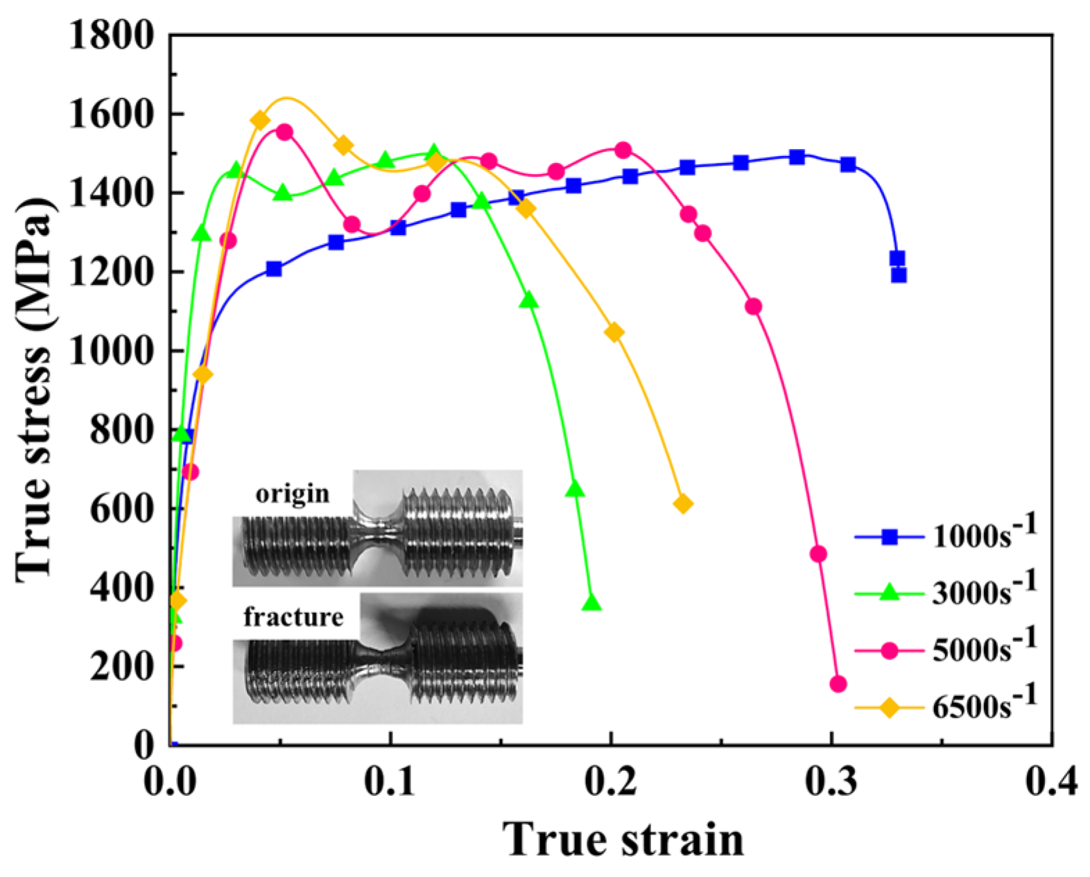
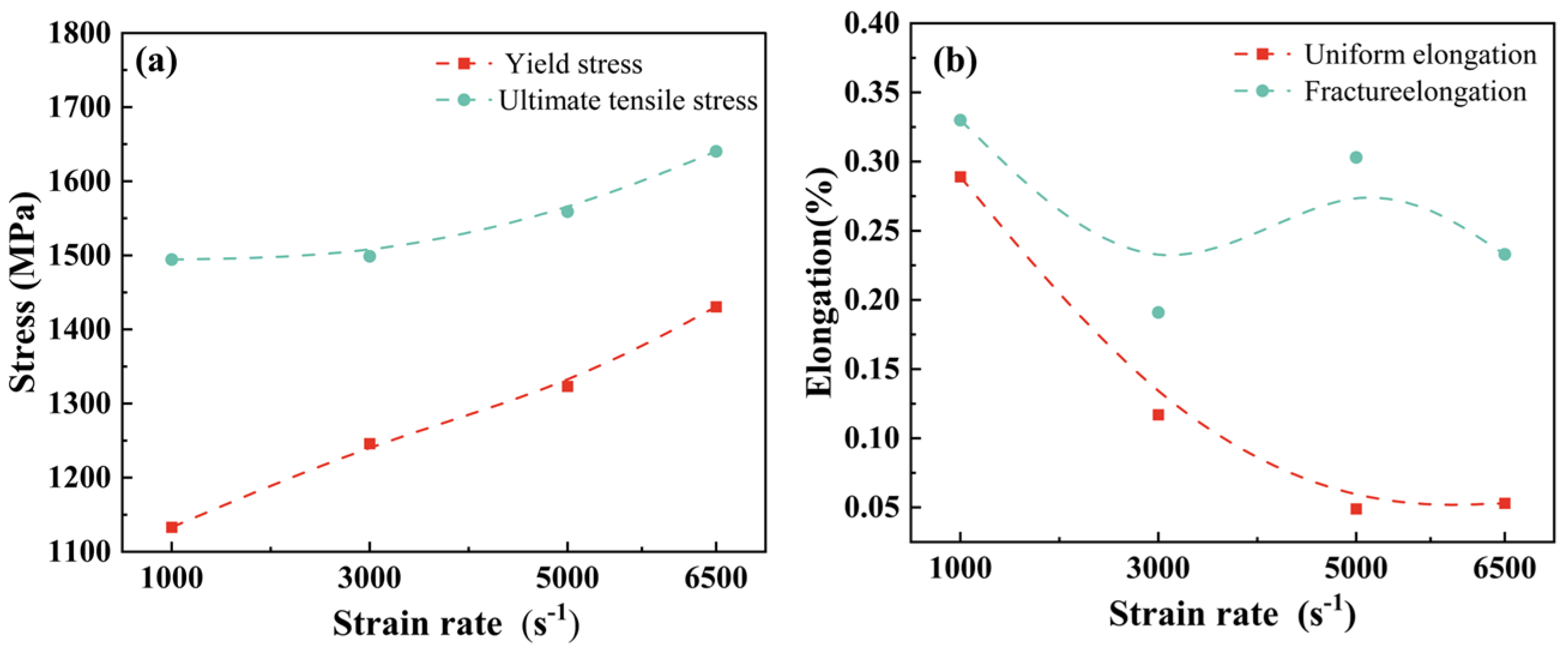
3.2. Dynamic Mechanical Properties

In the SHTB test, cylindrical specimens were used, which were connected to the bars through a threaded interface. In the SHTB experimental configuration, cylindrical specimens were implemented with precision-machined threaded interfaces to ensure robust connections with both the incident and transmission bars. This specimen design offers significant improvements over traditional plate-shaped specimens in two critical aspects: (i) it effectively eliminates interfacial debonding phenomena and enables reliable specimen retrieval, addressing persistent challenges associated with plate specimen configurations; (ii) the threaded connection mechanism provides superior mechanical coupling integrity, facilitating more uniform stress wave propagation and substantially reducing stress concentration factors during high-rate deformation. To establish statistical reliability and ensure reproducibility, a minimum of three independent tests were conducted for each strain rate condition. To establish statistical reliability and ensure experimental reproducibility, a minimum of three repeated tests were performed at each strain rate condition, with the acceptance criterion requiring at least two consistent and valid datasets for each testing condition.
The SHTB tests of the TWIP steel were carried out at different strain rates, from which the true stress–strain curves as well as the basic mechanical property indexes of the material under dynamic loading were obtained; the true stress–strain curve is shown in Figure 6, the basic mechanical property indexes are shown in Table 3. Comparing the macroscopic photos of the original specimen and the fractured specimen, it can be seen that the length of the specimen increased after dynamic stretching, and there is no obvious necking phenomenon near the fracture area, which indicates a uniform plastic deformation took place within the scaled section. The PSE results of TWIP steel show that the material can still maintain high energy absorption characteristics even at a high strain rate, especially at a strain rate of 5000 s−1.
Figure 7 illustrates the strain rate dependence of mechanical properties for the investigated material. The yield strength σ s demonstrates a positive strain rate sensitivity (PSRS) [40], exhibiting a monotonic increase with increasing strain rates. However, the σ b of the material decreased during the high strain rate transition from 3000 s−1 to 5000 s−1, as shown in Figure 7a. A comparison of elongation rates under different strain rates reveals that both uniform elongation and fracture elongation exhibit similar trends, decreasing overall with increasing strain rates, which is shown in Figure 7b. However, within the range of 3000~6500 s−1, the elongation rates show a notable increase at 5000 s−1, with both uniform elongation and fracture elongation rising at this specific strain rate.

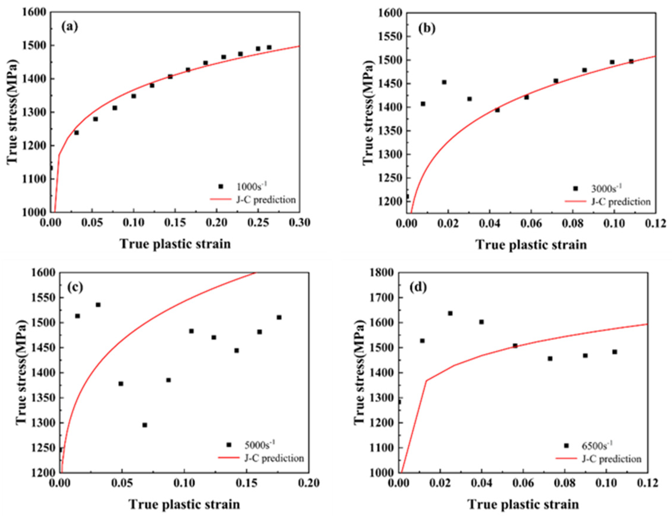
3.3. Fitting of the Material’s Johnson–Cook Constitutive Model

To predict the mechanical behavior of materials under varying strain rates and reduce experimental costs, it is crucial to develop a constitutive model that accurately captures the material’s response to different loading conditions. Empirical phenomenological models, such as the J-C model and the modified Ludwik model, are commonly used to fit experimental data and determine constitutive parameters. Among these, the J-C model is preferred due to its simplicity, computational efficiency, and ability to describe material behavior under high strain rates, large deformations, and temperature effects [41,42]. The J-C constitutive equation includes three key terms: strain hardening, strain rate sensitivity, and thermal softening, as shown in Equation (1).
σ = A + B ε p n 1 + C ln ε ˙ * 1 T * m
In this equation, A is the initial yield stress of the material at the reference strain rate ε ˙ o and the reference temperature T r . B and n are the strain hardening modulus and hardening index of the material at the reference strain rate ε ˙ o and the reference temperature T r , respectively. The C is the strain rate strengthening parameter of the material. The m is the thermal softening parameter of the material. σ is the flow stress, ε p is the equivalent plastic strain of the material, and ε ˙ * is the relative equivalent plastic strain rate (   ε ˙ * = ε ˙ / ε ˙ o , ε ˙ o is the reference strain rate taken as 1000 s−1). T * is the dimensionless temperature ( T * = (   T     T r )   / (   T m     T r ) , T r is the reference temperature taken as 293 K, T m is the melting point of the material and T is the test temperature.
Plastic deformation of materials during dynamic loading is usually accompanied by the coupled effects of work hardening, thermal softening, and strain rate hardening. The deformation at high strain rates usually behaves adiabatically, and part of the deformation work is usually converted to heat while the specimen temperature increases, so this temperature rise affects the material’s intrinsic behavior, and the expression for the adiabatic temperature rise is given by Equation (2):
Δ T = β ρ C p 0 ε σ ε d ε
where ρ    is the material density, take the value of 6.9;  C p    for the material isobaric specific heat capacity, take the value of 0.46 kJ/(kg·K);  β  is the conversion coefficient between the plastic work and thermal energy, metal materials are usually taken as 0.9; the right side of the equation plastic work integral term for the stress–strain curve surrounded by the area of the representation of the material, that is, the material’s plasticity absorption work.
According to the adiabatic temperature rise Equation (2) and the true stress–strain curve of the material, the  Δ T of the TWIP steel can be calculated for strain rates of 1000, 3000, 5000, and 6500 s−1, as shown in Table 4. Since the value of Δ T at each strain rate is within 200 °C, the effect of temperature rise on the material intrinsic structure can be considered to be negligible. Therefore, the thermal softening effect of the material under dynamic stretching at strain rates from 1000 to 6500 s−1 can be disregarded [28]. The temperature effect term of the J-C constitutive equation is neglected in this study, which is further simplified to Equation (3).
Considering the strain hardening term first, by performing quasi-static tensile tests, A is the yield stress obtained from the quasi-static tensile test, A = σ s = 833.12 MPa. By transforming Equation (4), the linear relationship between strain and stress can be obtained as shown in Equation (5), in which the reference strain rate is taken to be 1000 s−1. Based on the intercepts and slopes in the fitted results, the parameters B , n can be determined, with B = 845.56, n = 0.2.
σ = A + B ε p n
ln σ A = n l n B
By substituting the real stress–strain curve data of 1000~6500 s−1 strain rate, the strain range is taken as 0.04~0.1, and the corresponding stress values are taken at intervals of 0.02, which are substituted into Equation (6), and the obtained C values are averaged as the strain rate effect term parameter C    value, which is determined to be 0.08. The resulting J-C constitutive parameters are shown in Table 5, and the final J-C constitutive equations are given in Equation (6).
σ = A + B ε p n
σ = ( 833.12 + 845.56 ε p 0.2 ) ( 1 + 0.08 ln ε ˙ * )
The comparison between the predicted J-C constitutive model curve and the experimental data is shown in Figure 8. At a strain rate of 1000 s−1, the predicted curve fits well, as the strain hardening term in the constitutive equation is parameterized based on the reference strain rate of 1000 s−1, resulting in accurate predictions at this rate. However, at a strain rate of 3000 s−1, the thermal softening mechanism becomes more pronounced, leading to increased prediction errors. As the strain rate continues to increase, the curve begins to exhibit a wave-like pattern, indicating significant thermal softening effects. Despite the softening effects resulting in reduced strength, the strain hardening causes strength recovery [43]. It is because the competition mechanism between thermal softening and strain hardening causes the larger errors in the J-C fitting at high strain rates, suggesting that future adjustments to the temperature effect term may improve the model’s accuracy.

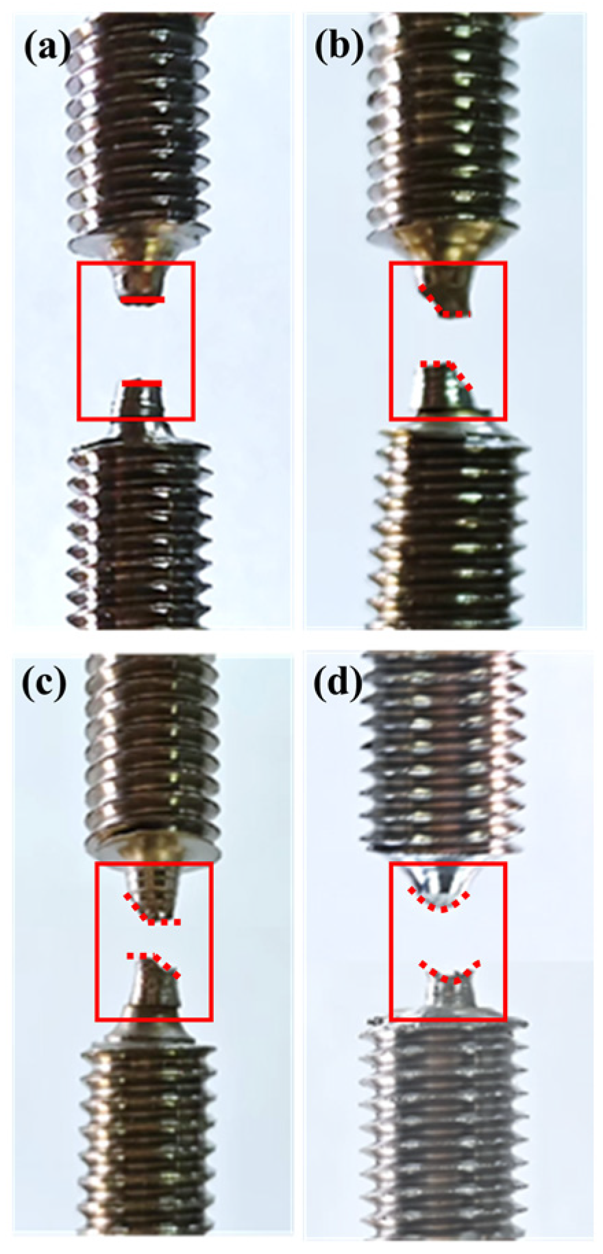
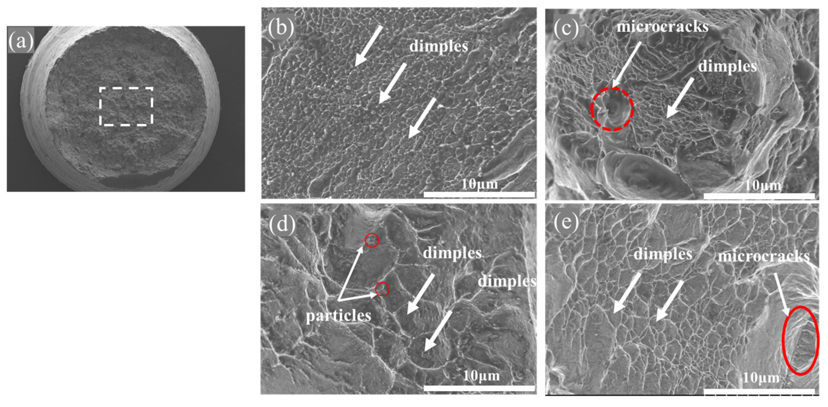
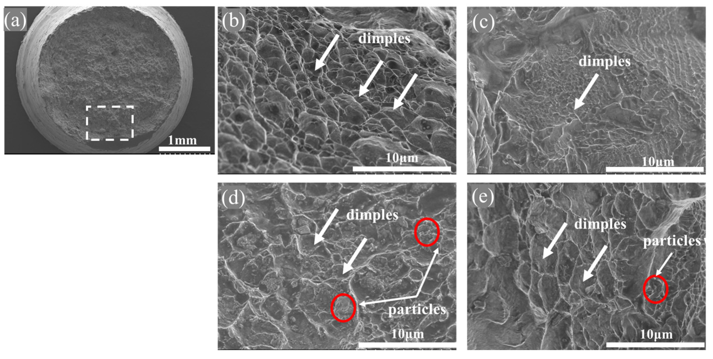
3.4. Fracture Failure Modes

It can be seen that the material fracture form of the TWIP specimen after pulling off in the high strain rate is different, as shown in the macroscopic fracture path in the red box in Figure 9. The surface of the material is basically a flat fracture at the 1000 s−1 strain rate, while the tensile stress that the material is subjected to is relatively low. The microcracks inside the material mainly expand gradually under a relatively uniform stress field, and the crystal structure inside the material has relatively sufficient time for coordinated deformation under this strain rate, so the material does not show a significant necking effect. Under the strain rate of 3000~5000 s−1, the material fracture shows an obvious 45° diagonal cut. While the tensile stress of the material increases rapidly, and at the same time, it produces a larger shear stress, the crack is more likely to expand along the direction of the maximum internal shear stress of the diagonal 45°. The material stress concentration at the fracture edge position is increased when the strain rate is increased to 6500 s−1 due to the local intense deformation of the material at high strain rate and uneven energy release, so the material fracture shows a petal-like shape with a concave center and a raised edge.
To investigate the fracture mechanism of the material under dynamic tensile testing, SEM observations were conducted on the fracture center and edge regions of fracture samples, while the sampling locations are illustrated in Figure 10a and Figure 11a, respectively. The SEM images of the fracture center under different strain rates are presented in Figure 11. The dimples in the matrix with different distributions indicate that the fracture mechanism of TWIP steel is characterized by ductile fracture. When the strain rate is 1000 s−1, the dimples shown by the white arrow in the figure are small in size and shallow in depth but densely distributed, so the toughness is good at this time, which is shown in Figure 10b. As shown in Figure 10c, the number of dimples remarked in the white arrow decreases, and larger holes remarked in the red circular dotted box are formed under the strain rate of 3000 s−1. These holes provide energy paths for crack formation and lead to a significant reduction in plasticity, at which time the TWIP steel exhibits the worst plasticity [44]. When the strain rate is raised to 5000 s−1, the dimples become larger and deeper, which is shown in Figure 10d. The Energy Dispersive Spectrometer (EDS) results in Figure 12 indicate that small particles near the dimples are mainly oxides of Fe and Mn. They are evenly distributed in the matrix and contribute to dispersion strengthening, which enhances the fracture elongation a of the TWIP steel [45]. At the strain rate of 6500 s−1, which is shown in Figure 10e, the number of dimples increases, but the large holes serve as potential crack initiation sites, resulting in poorer plasticity at this strain rate. The SEM image of the fracture edge region is shown in Figure 11. At a strain rate of 1000 s−1, the dimples are observed to be larger and deeper, exhibiting a uniform distribution. However, as the strain rate is increased to 3000 s−1, the dimples become shallower and are distributed non-uniformly. Conversely, the depth and size of the dimples increase at a strain rate of 5000 s−1, accompanied by an increase in the number of particles in the vicinity. At 6500 s−1, the number of dimples remains relatively unchanged, but their depth decreases. The SEM observations of the fracture morphology at both the center and edge demonstrate analogous trends, and the variation in material plasticity with strain rate is consistent across both regions.

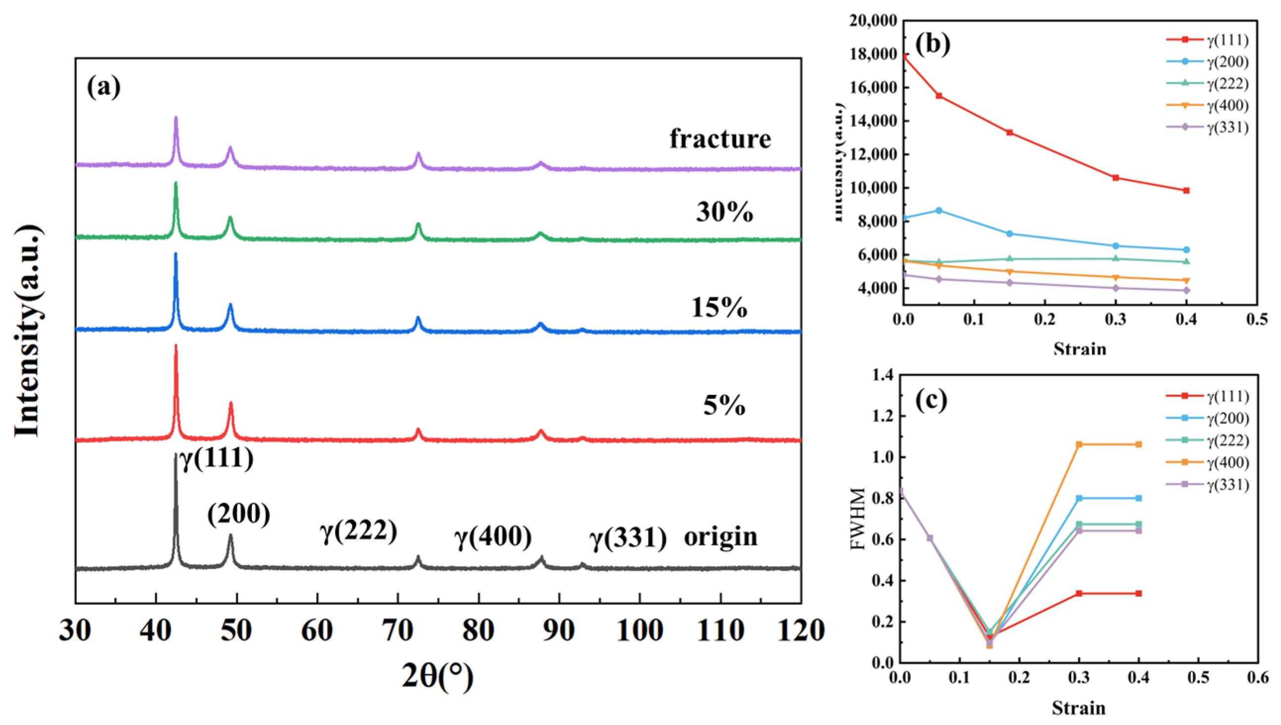
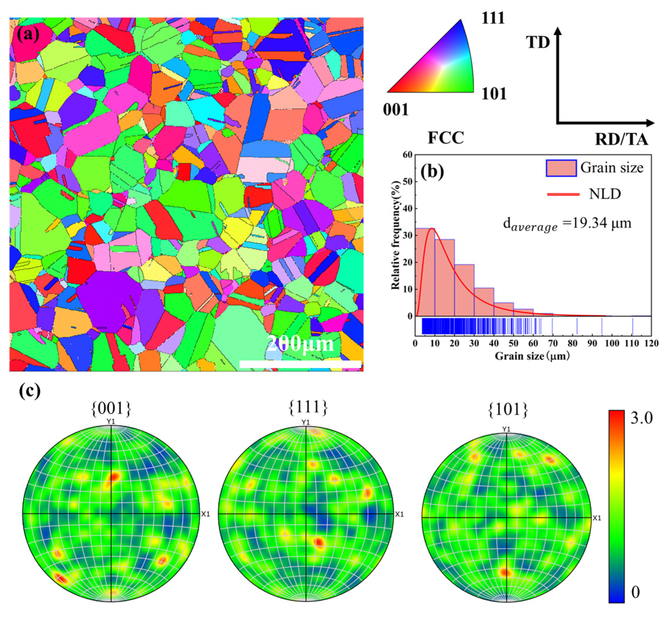
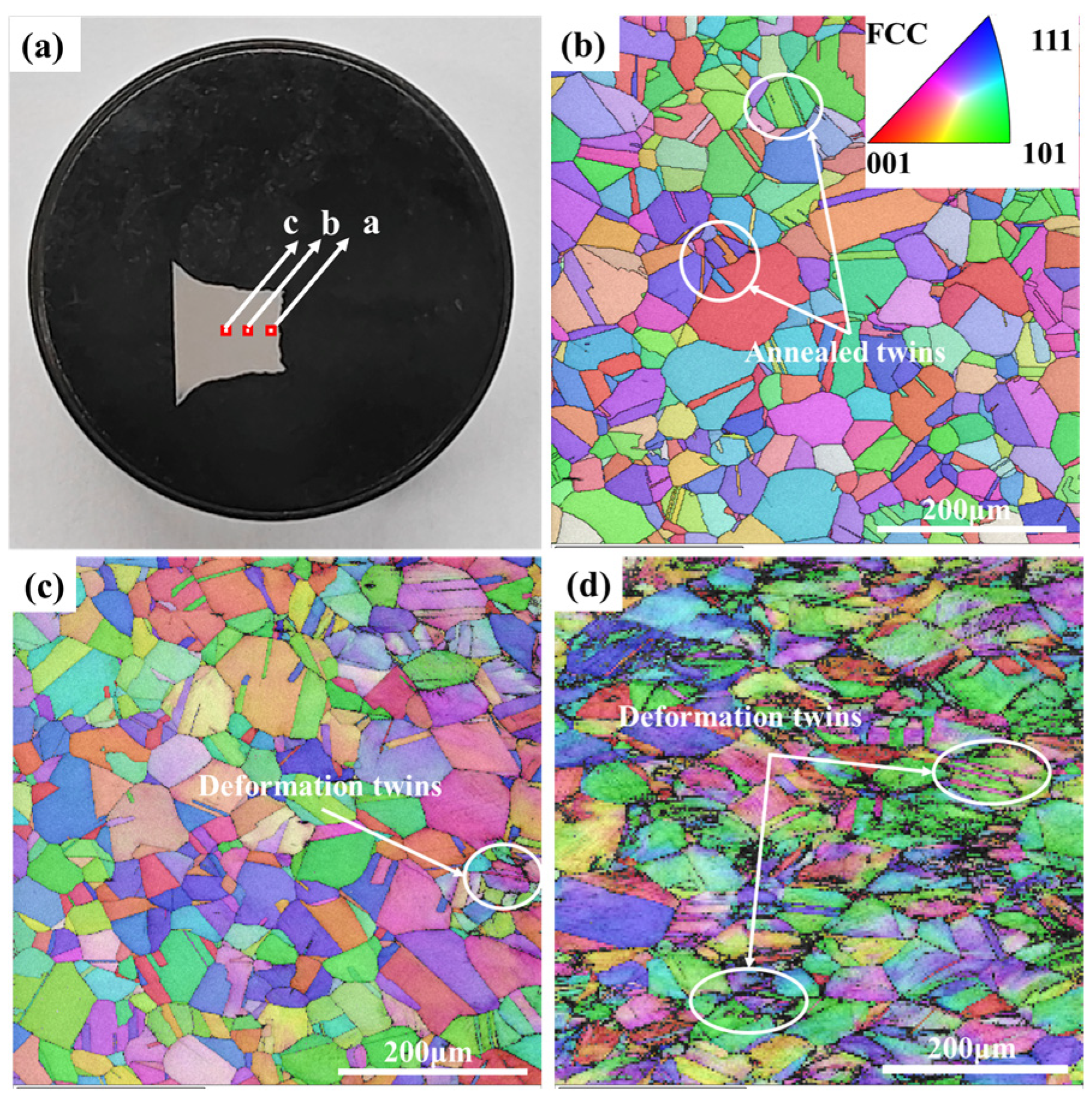
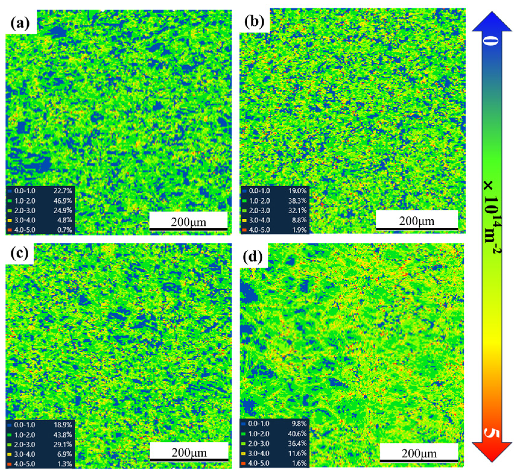
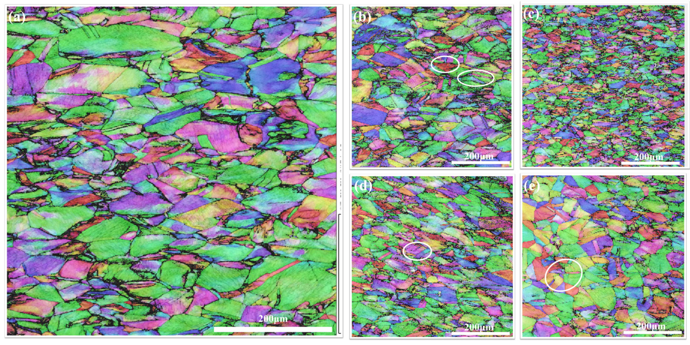
3.5. Microstructural Evolution and Deformation Mechanisms

The first original sample IPF figure calculated the average grain size, and normal logarithmic distribution (NLD) curves were obtained by using EBSD technology, which are shown in Figure 13. EBSD analysis indicates that the material was completely austenitic, with an average grain size of 19.34 μm and annealing twins. In addition, no preferential texture was found, which is critical for evaluating the microstructure evolution during deformation.
To investigate the deformation mechanism of Fe-Mn-Al-Ni-C TWIP steel, EBSD analysis was performed on fracture specimens with a strain rate of 1000 s−1. The EBSD images are taken from points “a”, “b”, and “c” at varying distances from the fracture, which are shown in Figure 14a. The specimens predominantly exhibit an austenitic structure with no phase transformation. As the distance from the fracture center increases, the zero-resolution area becomes more prevalent, which means that the material is subjected to worse stress concentration. Comparison of Figure 14b–d reveals that grains near the fracture center are more elongated, and grain fragmentation becomes more pronounced under strain. At point “c” in Figure 15b, the grains are uniformly distributed with an average size of 20 μm, and twinning is evident, with a twinning boundary fraction of 49.1%. At point “b”, near the fracture, the twinning boundary fraction decreases to 47.2%, and lens-shaped deformation twins are present, though in smaller amounts, which is shown in Figure 14c. At point “a”, which is shown in Figure 14c, the grain refinement is more pronounced with a noticeable woven texture in the center of the fracture samples. The twinning boundary fraction further decreases to 10.2%, and lamellar or network-like structures appear in the grain; the prominent deformation twins were marked by white wireframe patterns. It can be seen that the activation of a twinning process takes place in the consecutive grains with orientations [111] and [001]; that is, the effect of the initial texture on the twinning activity decreases. There are no deformation twins in the orientation [001], which is consistent with the conclusion of Jabłońska’s study [46].
To investigate the role of dislocation slip in the deformation of TWIP steel under different strain rates, the geometric dislocation density after deformation was analyzed by using EBSD; the geometrically necessary dislocation (GND) images are shown in Figure 15. The Rainbow color scale is used to indicate dislocation density. Generally, as the strain applied to the material increases and stress becomes more concentrated, the geometric dislocation density increases, with the color shifting towards red. It is evident that the dislocation density rises with increasing strain rate, and the red regions are primarily concentrated near grain boundaries. This suggests that most twins form near the grain boundaries [47]. The grain boundaries act as barriers to dislocation movement, causing dislocations to become entangled and increasing the stress concentration at these boundaries [48]. This facilitates the nucleation and growth of twins. At higher strain rates, the dislocation density near grain boundaries becomes more pronounced, enabling deformation twins to form more quickly. The formation of twins further obstructs dislocation motion, reducing their average free path, and resulting in the “dynamic Hall-Petch” effect [49].
Figure 16 shows the EBSD diagram of the fracture of TWIP steel after tensile fracture in the central part with a strain rate of 10−4 and 1000–5000 s−1. It can be seen that part of the deformation twins penetrate through the entire original grain during quasi-static loading, which makes the grain of the material refined, which is shown in Figure 16a. At this time, the zero resolution at the grain boundary is relatively large, which is due to the staggered entanglement of the dislocation, which aggravates the stress concentration at the grain boundary, and micro-cracks are easy to initiation and expansion, resulting in the failure fracture of the material, and the volume fraction of the twin boundary is 15.9%. The increase in strain rate makes the stress concentration of the material more serious than that of the quasi-static state. At a strain rate of 1000 s−1, deformation twins appear inside the grain, as shown in the white wire frame in Figure 16b, and the ratio of the twin boundary is 10.2%. When the strain rate is 3000 s−1, which is demonstrated in Figure 16c, the proportion of twin boundary is 9.29%, and the degree of grain refinement and breakage is high. The percentage of unresolved area around the grain boundary increases to 20.6%, which indicates that the stress concentration of the material is serious at this strain rate, and the nucleation and expansion of crack sources are easy to occur near the grain boundary, so the plasticity of the material is relatively low. When the strain rate is 5000 s−1, the proportion fraction of twin boundary is 8.58%, and a secondary twin system with different orientation from the initial deformation twin appears inside the grain, and the angle between the secondary twin and the initial twin is 57.8°~59.8°, which accords with the Angle range between the initial twin and the secondary twin [50], the white wire frame also shows the deformation twins in grain in Figure 16d. The two groups of twins deliver each other during the stretching process. The plasticity of the material is improved at this time as the grain is further divided into multiple pieces and refined by the twins. The strain rate gradually increases to 6500 s−1, and the fraction of twin boundary increases to 18.7%. The reduction of grain breakage degree shown in Figure 16e is due to the fact that multi-twin system shown in the white circular frame formed inside the grain can absorb deformation energy and thus reduce stress concentration. The relevant study shows that the increase of grain size leads to the decrease of the critical stress generated by deformation twins, resulting in the continuous formation of deformation twins during tensile deformation, resulting in continuous work hardening effect, with obvious “TWIP effect” [51], and the increase of secondary twins.

4. Conclusions

In this paper, the quasi-static dynamic mechanical properties of TWIP steel ranging from 10−4 s−1 to 6500 s−1 were investigated. The J-C constitutive parameters and material constitutive equation of TWIP steel are obtained by multi-parameter fitting. The influences of strain rate on mechanical behaviors and deformation mechanisms were explored by comparing the microstructure at different strain rates. The main conclusions are as follows:
(1)
Fe-Mn-Al-Ni-C TWIP steel maintains a single phase throughout varying strain conditions, suggesting that tensile deformation is characterized solely by twinning.
(2)
TWIP steel demonstrates PSRS under both quasi-static and dynamic conditions. Plasticity diminishes with increasing strain rate, with 5000 s−1 marking a critical point for enhanced plasticity and superior overall mechanical properties.
(3)
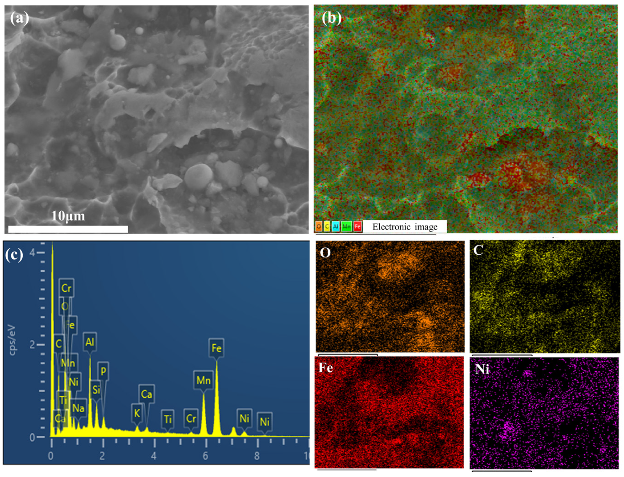
Macroscopic fracture morphology evolves with strain rate, yet the microscopic fracture mechanism remains ductile across all rates. At 5000 s−1, Fe and Mn oxides are evenly dispersed within the matrix near the dimples, contributing to plastic strengthening.
(4)
The J-C material constitutive equation obtained through multi-parameter fitting cannot ignore the temperature term. This is due to the complex competitive relationship between strain hardening and thermal softening effects during the deformation process of TWIP steel.
(5)
The twinning mechanism is more active at high strain rates compared to quasi-static conditions. As the strain rate increases, dislocations near grain boundaries and twins become increasingly entangled, leading to a rise in dislocation density. This promotes twin nucleation near grain boundaries. At a strain rate of 5000 s−1, secondary twin systems can be activated, resulting in grain refinement and further hindering dislocation slip, thereby enhancing strength.

Author Contributions

Conceptualization and methodology: all authors; formal analysis: J.Y., X.L. and Y.T.; investigation: J.Y., X.L. and Y.T.; resources and funding acquisition: X.L.; writing—original draft preparation: J.Y. and X.L.; data curation: S.B. and Y.Y.; writing—review and editing: M.H. and M.X. All authors have read and agreed to the published version of the manuscript.

Funding

This research was funded by the National Natural Science Foundation of China, grant number 52178178.

Data Availability Statement

The original contributions presented in the study are included in the article, further inquiries can be directed to the corresponding author.

Conflicts of Interest

The authors declare no conflicts of interest. The funders had no role in the design of the study; in the collection, analyses, or interpretation of data; in the writing of the manuscript; or in the decision to publish the results.

References

  1. Grässel, O.; Krüger, L.; Frommeyer, G.; Meyer, L. High strength Fe-Mn-(Al, Si) TRIP/TWIP steels development—Properties—Application. Int. J. Plast. 2000, 16, 1391–1409. [Google Scholar] [CrossRef]
  2. Chowdhury, P.; Canadinc, D.; Sehitoglu, H. On deformation behavior of Fe-Mn based structural alloys. Mater. Sci. Eng. R 2017, 122, 1–28. [Google Scholar] [CrossRef]
  3. Mintz, B.; Qaban, A. The Influence of Precipitation, High Levels of Al, Si, P and a Small B Addition on the Hot Ductility of TWIP and TRIP Assisted Steels: A Critical Review. Metals 2022, 12, 502. [Google Scholar] [CrossRef]
  4. Qin, X.M.; Chen, L.Q.; Deng, W.; Di, H.S. Effect of strain rate on mechanical properties of Fe-23Mn-2Al-0.2C TWIP steel. CJMR 2011, 25, 278–282. (In Chinese) [Google Scholar]
  5. Deng, J.H.; Li, C.W.; Wang, Z.Y.; Tong, W.; Wu, Q.Y. Effect of post-weld heat treatment on microstructure and mechanical properties of twinning-induced plasticity (TWIP) steel joints. Mater. Today Commun. 2024, 40, 109720. [Google Scholar] [CrossRef]
  6. Xu, J.P.; Wang, Z.; Yan, Y.; Li, J.X.; Wu, M. Effect of hot/warm rolling on the microstructures and mechanical properties of medium-Mn steels. Mater. Charact. 2020, 170, 110682. [Google Scholar] [CrossRef]
  7. Wesselmecking, S.; Kreins, M.; Dahmen, M.; Bleck, W. Material oriented crash-box design—Combining structural and material design to improve specific energy absorption. Mater. Des. 2022, 213, 110357. [Google Scholar] [CrossRef]
  8. Fajardo, S.; Llorente, I.; Jiménez, J.A.; Bastidas, J.M.; Bastidas, D.M. Effect of Mn additions on the corrosion behaviour of TWIP Fe-Mn-Al-Si austenitic steel in chloride solution. Corros. Sci. 2019, 154, 246–253. [Google Scholar] [CrossRef]
  9. Wang, Y.N.; Li, Q.; He, Y.L.; Fu, R.Y.; Li, L. Microstructure and properties of high strength and high plasticity TWIP steel. Heat Treat. 2006, 154, 25–30. (In Chinese) [Google Scholar]
  10. Liu, X.H.; Liu, W.; Liu, J.B.; Shu, K.Y. Research status of twin-induced plasticity (TWIP) steel. Mater. Rep. 2010, 11, 102–105. (In Chinese) [Google Scholar]
  11. Madivala, M.; Schwedt, A.; Wong, S.L.; Roters, F.; Prahl, U.; Bleck, W. Temperature dependent strain hardening and fracture behavior of TWIP steel. Int. J. Plast. 2018, 104, 80–103. [Google Scholar] [CrossRef]
  12. Cui, X.W.; Zhang, G.J.; Lin, S.F. Effect of Mn content on microstructure and properties of hot rolled TWIP steel. Cailiao Rechuli Xuebao 2022, 43, 92–98. (In Chinese) [Google Scholar] [CrossRef]
  13. An, Y.F.; Chen, X.P.; Mei, L.; Ren, P.; Wei, D.; Cao, W.Q. Precipitation transformation pathway and mechanical behavior of nanoprecipitation strengthened Fe-Mn-Al-C-Ni austenitic low-density steel. J. Mater. Sci. Technol. 2024, 7, 157–167. [Google Scholar] [CrossRef]
  14. Guo, P.C.; Qian, L.H.; Meng, J.Y.; Liu, S.; Zhang, F. Effect of Al on the low cycle fatigue deformation behavior and microstructure evolution of Fe-22Mn-0.6C TWIP steel. JMR&T 2024, 30, 2086–2098. [Google Scholar] [CrossRef]
  15. Chu, C.M.; Huang, H.; Kao, P.W.; Gan, D. Effect of alloying chemistry on the lattice constant of austenitic Fe-Mn-Al-C alloys. Scr. Metall. Mater. 1994, 30, 505–508. [Google Scholar] [CrossRef]
  16. Yang, Z.B.; Zhu, D.Y.; Yi, W.F.; Lin, S.M. Effect of carbon content on strain hardening behavior of Fe-Ni-Mn-Si-C TWIP steels. Iron Steel 2011, 46, 69–73. [Google Scholar]
  17. Wen, H.Y.; Zhu, D.Y.; Wang, M.J.; Qiao, W.; Liao, L. Effect of carbon content on microstructure and mechanical properties of new Fe-Ni-Mn-Si-C TWIP steel. Iron Steel 2010, 45, 74–78. [Google Scholar]
  18. Akinay, Y.; Hayat, F. Effect of Ni on the mechanical behavior of a high-Mn austenitic TWIP steel. Mater. Test. 2016, 58, 413–417. [Google Scholar] [CrossRef]
  19. Wang, Y.C.; Lan, P.; Li, Y.; Zhang, J.Q. Influence of alloying elements on mechanical behavior of Fe-Mn-C TWIP steel. Cailiao GongGheng 2015, 9, 30–38. (In Chinese) [Google Scholar]
  20. Lu, S.; Wang, Q.C.; Yao, T.T.; Feng, H.; Gao, M.; Xi, T.; Li, H.B.; Tan, L.; Yang, K. Simultaneous improvement of strength and plasticity: Nano-twin construction for a novel high-nitrogen TWIP steel. Int. J. Plast. 2024, 183, 104144. [Google Scholar] [CrossRef]
  21. Feng, X.C.; Liu, X.Y.; Bai, S.X.; Ye, Y.C.; Zong, L.; Tang, Y. Mechanical properties and deformation behaviour of TWIP steel at different strain rates (vol 879, 145182, 2023). Mater. Sci. Eng. A Struct. Mater. Prop. Microstruct. Process. 2023, 882, 145414. [Google Scholar] [CrossRef]
  22. Xue, K.R.; Qiao, K.; Zhang, T.; Gao, F.; Yao, J.C.; Wang, W.; Wang, K.S. Hot Deformation Behavior and Dynamic Recrystallization Mechanism of Fe-18.2Mn-0.52C Twinning-Induced Plasticity Steel. JOM 2024, 76, 6457–6471. [Google Scholar] [CrossRef]
  23. Sklate Boja, M.F.; Giordana, M.F.; Banegas, S.; Druker, A.V. Twinning-Induced Plasticity Steel for the Automotive Industry: Design Stress for Gas Tungsten Arc Welded Parts. J. Mater. Eng. Perform. 2024, 1–15. [Google Scholar] [CrossRef]
  24. Yang, N.; Wang, X.; Liang, J.; Deng, H.X.; Ma, J.G.; Liu, Z.H.; Han, F.S. Characterization of microstructures and mechanical properties of laser welded TWIP steel plate. J. Mater. Res. Technol. 2024, 30, 7228–7241. [Google Scholar] [CrossRef]
  25. Santos GJ, D.; Colombo TC, A.; REgo, R.R.; Otubo, J. Integrity evolution during dissimilar welding of TWIP steel. J. Mater. Res. Technol. 2023, 27, 4461–4468. [Google Scholar] [CrossRef]
  26. Deng, H.X.; Liu, Z.H.; Wang, X.F.; Ma, J.G.; Wu, J.F.; Han, F.S. Microstructure and mechanical properties of heat affected zone for high-Mn TWIP steel based on welding thermal simulation. Hanjie Xuebao/Trans. China Weld. Inst. 2023, 44, 83–89. [Google Scholar] [CrossRef]
  27. Zhong, Y.L.; Li, G.Q. Concept and hysteretic behavior studies of TWIP steel made metallic energy dissipater. J. Constr. Steel Res. 2021, 186 (Suppl. C), 106911. [Google Scholar] [CrossRef]
  28. Feng, X.C.; Liu, X.Y.; Bai, S.X.; Tang, Y.; Ye, Y.C. Investigation of dynamic tensile mechanical responses and deformation mechanism at high strain rates in a TWIP steel. J. Mater. Res. Technol. 2023, 26, 639–653. [Google Scholar] [CrossRef]
  29. Zhang, C.; Han, Y.; Teng, H.X.; Liu, H.S.; Xie, C.Q.; Su, Y.J. Enhancement of hydrogen embrittlement resistance in high manganese steel under in-situ electrochemical hydrogen charging by regulating the grain size and distribution. Int. J. Hydrogen Energy 2024, 82, 968–978. [Google Scholar] [CrossRef]
  30. Chen, Y.; Liu, G.M.; Li, H.Y.; Zhang, X.M.; Ding, H. Microstructure, strain hardening behavior, segregation and corrosion resistance of an electron beam welded thick high-Mn TWIP steel plate. J. Mater. Res. Technol. 2023, 25, 1105–1114. [Google Scholar] [CrossRef]
  31. Opiela, M.; Grajcar, A.; Krukiewicz, W. Corrosion behaviour of Fe-Mn-Si-Al austenitic steel in chloride solution. J. Achiev. Mater. Manuf. Eng. 2009, 33, 159–165. [Google Scholar]
  32. Ai, G.G.; Jiang, F.Y.; Si, F.; Liu, J.N.; Wei, N.; Wang, J.B. Effect of annealing process on microstructure and corrosion resistance of high-Mn TWIP steel. Jinshu Rechuli/Heat Treat. Met. 2024, 49, 313–321. [Google Scholar] [CrossRef]
  33. Jo, Y.H.; Cho, H.J.; Yang, J.H.; Lee, S.J. Enhancing charpy absorbed energy of aged duplex lightweight steel plates through TRIP and TWIP mechanisms. Mater. Charact. 2024, 217, 114413. [Google Scholar] [CrossRef]
  34. Martin, S.; Weidner, A.; Ullrich, C.; Schimpf, C.; Motylenko, M.; Lehnert, R.; Biermann, H.; Rafaja, D.; Vinogradov, A.; Estrin, Y. Deformation behaviour of TWIP steels: Constitutive modelling informed by local and integral experimental methods used in concert. Mater. Charact. 2022, 184, 111667. [Google Scholar] [CrossRef]
  35. GB/T 228.1-2010; Metallic Materials—Tensile Tests—Part 1: Test Method at Room Temperature. Standardization Administration of China: Beijing, China, 2010.
  36. GB/T 30069.1-2013; High Strain Rate Tensile Tests for Metallic Materials—Part 1: Elastic Rod Type Systems. Standardization Administration of China: Beijing, China, 2013.
  37. Lan, P.; Zhang, J. Tensile property and microstructure of Fe-22Mn-0.5C TWIP steel. Mater. Sci. Eng. A 2017, 707, 373–382. [Google Scholar] [CrossRef]
  38. Lan, P.; Zhang, J. Serrated Flow and Dynamic Strain Aging in Fe-Mn-C TWIP Steel. Metall. Mater. Trans. A Phys. Metall. Mater. Sci. 2018, 49A, 147–161. [Google Scholar] [CrossRef]
  39. Li, Y.Z.; Liang, Z.Y.; Huang, M.X. Strengthening contributions of dislocations and twins in warm-rolled TWIP steels. Int. J. Plast. 2022, 150, 103198. [Google Scholar] [CrossRef]
  40. Chumlyakov, Y.; Maier, H.J.; Sehitoglu, H.; Canadinc, D.; Niklasch, D. Orientation evolution in Hadfield steel single crystals under combined slip and twinning. Int. J. Solids Struct. 2007, 44, 34–50. [Google Scholar]
  41. Guo, Z.; Gao, B.; Guo, Z.; Zhang, W. Dynamic constitutive relationship of Q235 steel based on J-C model. Expl. Shock Wave 2018, 38, 804–810. (In Chinese) [Google Scholar] [CrossRef]
  42. Lin, H.; Jin, G.; Zhan, Q.; Wang, G.; Han, J. Mechanical Properties and Constitutive Model of TC4 Titanium Alloy at Cryogenic. J. Mater. Eng. Perform. 2023, 33, 13731–13743. [Google Scholar] [CrossRef]
  43. Li, C.; Fang, W.; Yu, H.Y.; Peng, T.; Yao, Z.T.; Liu, W.G.; Zhang, X.; Xu, P.; Yin, F. The BCC → FCC hierarchical martensite transformation under dynamic impact in FeMnAlNiTi alloy. Mater. Sci. Eng. A 2024, 892, 146096. [Google Scholar] [CrossRef]
  44. Ye, T.; Zhao, F.; Chen, L.Y.; Jiang, K.; Deng, Q.; Chen, Y.Z.; Wang, Q.Y.; Suo, T. Effect of strain rate and low temperature on mechanical behaviour and microstructure evolution in twinning-induced plasticity steel. Mater. Sci. Eng. A 2021, 823, 141734. [Google Scholar] [CrossRef]
  45. Li, D.D.; Qian, L.H.; Wei, C.Z.; Liu, S.; Zhang, F.C.; Meng, J.Y. The tensile properties and microstructure evolution of cold-rolled Fe–Mn–C TWIP steels with different carbon contents. Mater. Sci. Eng. A 2022, 839, 142862. [Google Scholar] [CrossRef]
  46. Jabłońska, M.B.; Archie, F. Effect of the strain rate on the deformation mechanisms of TWIP-type steel. Mater. Sci. Eng. A 2024, 915, 147219. [Google Scholar] [CrossRef]
  47. Shen, S.C.; Xie, P.; Wu, C.L.; Luo, J.; Ye, H.F.; Chen, J.H. Cross-slip of extended dislocations and secondary deformation twinning in a high-Mn TWIP steel. Int. J. Plast. 2024, 175, 103922. [Google Scholar] [CrossRef]
  48. Cai, W.; Sun, C.; Zhang, H.; Wang, C.; Meng, L.; Fu, M.W. Delving into the intrinsic co-relation between microstructure and mechanical behaviour of fine-/ultrafine-grained TWIP steels via TEM and in-situ EBSD observation. Mater. Charact. 2024, 210, 113780. [Google Scholar] [CrossRef]
  49. Xie, P.; Wu, C.L.; Chen, J.H. Electron microscopic characterization of deformed twin boundary defects in high manganese TWIP steel. Dianzi Xianwei Xuebao 2023, 42, 596–604. (In Chinese) [Google Scholar]
  50. Feng, X.C.; Liu, X.Y.; Tang, Y.; Bai, S.X.; Zhu, L.A. Study on dynamic mechanical properties and deformation mechanism of TWIP steel. Xiyou Jinshu Cailiao Yu Gongcheng 2023, 52, 1695–1707. (In Chinese) [Google Scholar]
  51. Wang, S.H.; Liu, Z.Y.; Wang, G.D. Influence of grain size on TWIP effect in TWIP steel. Jinshu Xuebao 2009, 45, 1083–1090. (In Chinese) [Google Scholar] [CrossRef]
Figure 1. Schematic of the dimensions of the quasi-static tensile specimen (unit: mm).
Buildings 15 00897 g001
Figure 2. Schematic of the dimensions of the dynamic tensile specimen (unit: mm).
Buildings 15 00897 g002
Figure 3. Quasi-static tensile specimen. (a) Photograph of the primary specimen; (b) strain gauge arrangement; (c) macroscopic comparison of the specimen before and after tensile tests.
Buildings 15 00897 g003
Figure 4. Quasi-static mechanical performance curve of TWIP steel. (a) Engineering stress–strain; (b) True stress–strain.
Buildings 15 00897 g004
Figure 5. (a) XRD patterns; (b) peak intensity; (c) FWHM of TWIP steel at different strains.
Buildings 15 00897 g005
Figure 6. True stress–strain curve of TWIP steel and macroscopic images of the specimen before and after tensile deformation.
Buildings 15 00897 g006
Figure 7. Comparison of material properties at different strain rates. (a) Strength; (b) Plasticity.
Buildings 15 00897 g007
Figure 8. Comparison of experimental data and J-C model predictions at different strain rates. (a) 1000 s−1; (b) 3000 s−1; (c) 5000 s−1; (d) 6500 s−1.
Buildings 15 00897 g008
Figure 9. Macroscopic fracture images of TWIP steel at different strain rates. (a) 1000 s−1; (b) 3000 s−1; (c) 5000 s−1; (d) 6500 s−1.
Buildings 15 00897 g009
Figure 10. SEM results of the specimen center at different strain rates. (a) observation position; (b) 1000 s−1; (c) 3000 s−1; (d) 5000 s−1; (e) 6500 s−1.
Buildings 15 00897 g010
Figure 11. SEM results of the specimen edge at different strain rates. (a) observation position; (b) 1000 s−1; (c) 3000 s−1; (d) 5000 s−1; (e) 6500 s−1.
Buildings 15 00897 g011
Figure 12. (a) Origin image; (b) the element distribution; (c) the phase distribution diagram of particulate area by EDS.
Buildings 15 00897 g012
Figure 13. (a) IPF-Z; (b) grain size distribution; (c) pole figures of origin annealed TWIP steel.
Buildings 15 00897 g013
Figure 14. EBSD images of the specimen at different distances from the fracture under a strain rate of 1000 s−1. (a) Sampling points; (b) EBSD map of point c; (c) EBSD map of point b; (d) EBSD map of point a.
Buildings 15 00897 g014
Figure 15. GND images of the specimen at different strain rates. (a) 1000 s−1; (b) 3000 s−1; (c) 5000 s−1; (d) 6500 s−1.
Buildings 15 00897 g015
Figure 16. EBSD images of the fracture center at different strain rates. (a) 10−4 s−1; (b) 1000 s−1; (c) 3000 s−1; (d) 5000 s−1; (e) 6500 s−1.
Buildings 15 00897 g016
Table 1. The primary chemical elements of TWIP steel (in wt.%).
MnAlNiCSiFe
29.2008.8006.0001.2000.090Bal.
Table 2. Quasi-static mechanical properties of TWIP steel.
Strain Rate
/s−1
Yield Stress
σ s /MPa
Ultimate Tensile Stress
σ b /MPa
Yield RatioUniform Elongation
%
Fracture Elongation
/%
PSE
/MPa%
10−2958.611448.070.660.3570.37554,303
10−3898.931526.130.590.4100.44367,608
10−4833.121411.140.590.4230.43761,667
Table 3. Quasi-static mechanical properties of TWIP steel.
Strain Rate
/s−1
Yield Stress
σ s /MPa
Ultimate Tensile Stress
σ b /MPa
Yield RatioUniform Elongation
%
Fracture Elongation
/%
PSE
/MPa%
10001133.01494.30.760.2890.33049,279
30001245.91498.80.840.1170.19128,627
50001323.21558.90.850.0490.30347,234
65001430.61640.30.870.0530.23338,220
Table 4. Adiabatic temperature rise and plastic work absorption under different strain rate conditions.
Strain Rate ε ˙ o 1000300050006500
Δ T 123.2368.84108.2783.94
Plastic Energy Absorption442.23245.84386.68299.79
Table 5. Constitutive parameters obtained from Johnson–Cook fitting.
A /MPa B n C
833.12845.560.20.08
Disclaimer/Publisher’s Note: The statements, opinions and data contained in all publications are solely those of the individual author(s) and contributor(s) and not of MDPI and/or the editor(s). MDPI and/or the editor(s) disclaim responsibility for any injury to people or property resulting from any ideas, methods, instructions or products referred to in the content.

