
Large Deformation Mechanism and Support Countermeasures of Deep-Buried Soft Rock Tunnels Under High Geostress State

Abstract
1. Introduction
2. Project Background
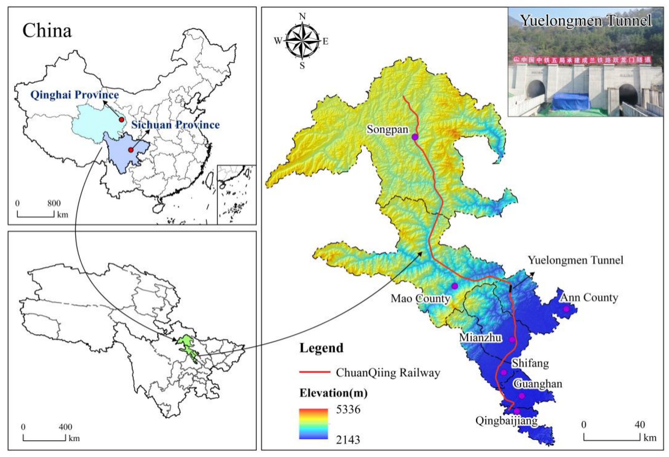
2.1. Project Overview
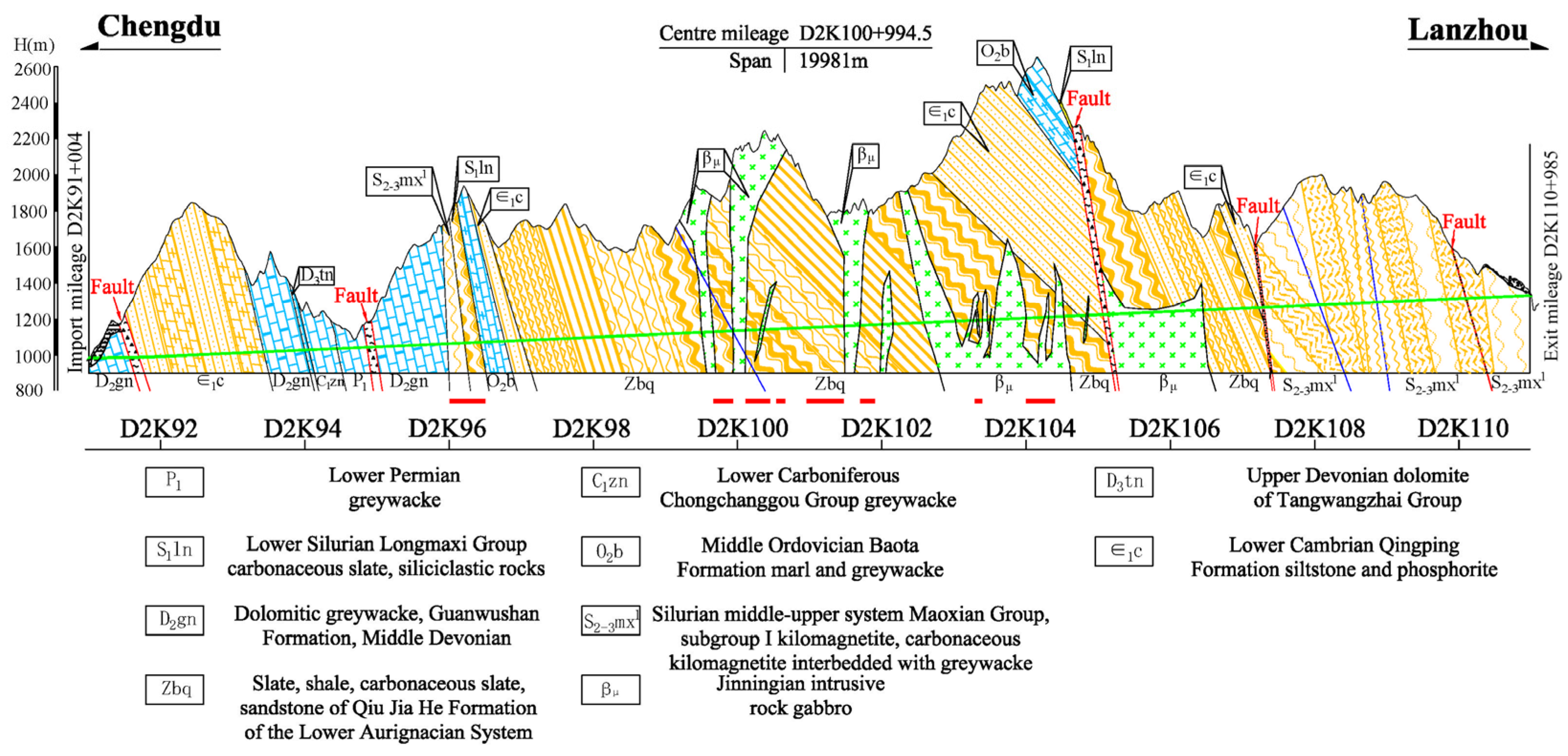
2.2. Engineering Geology
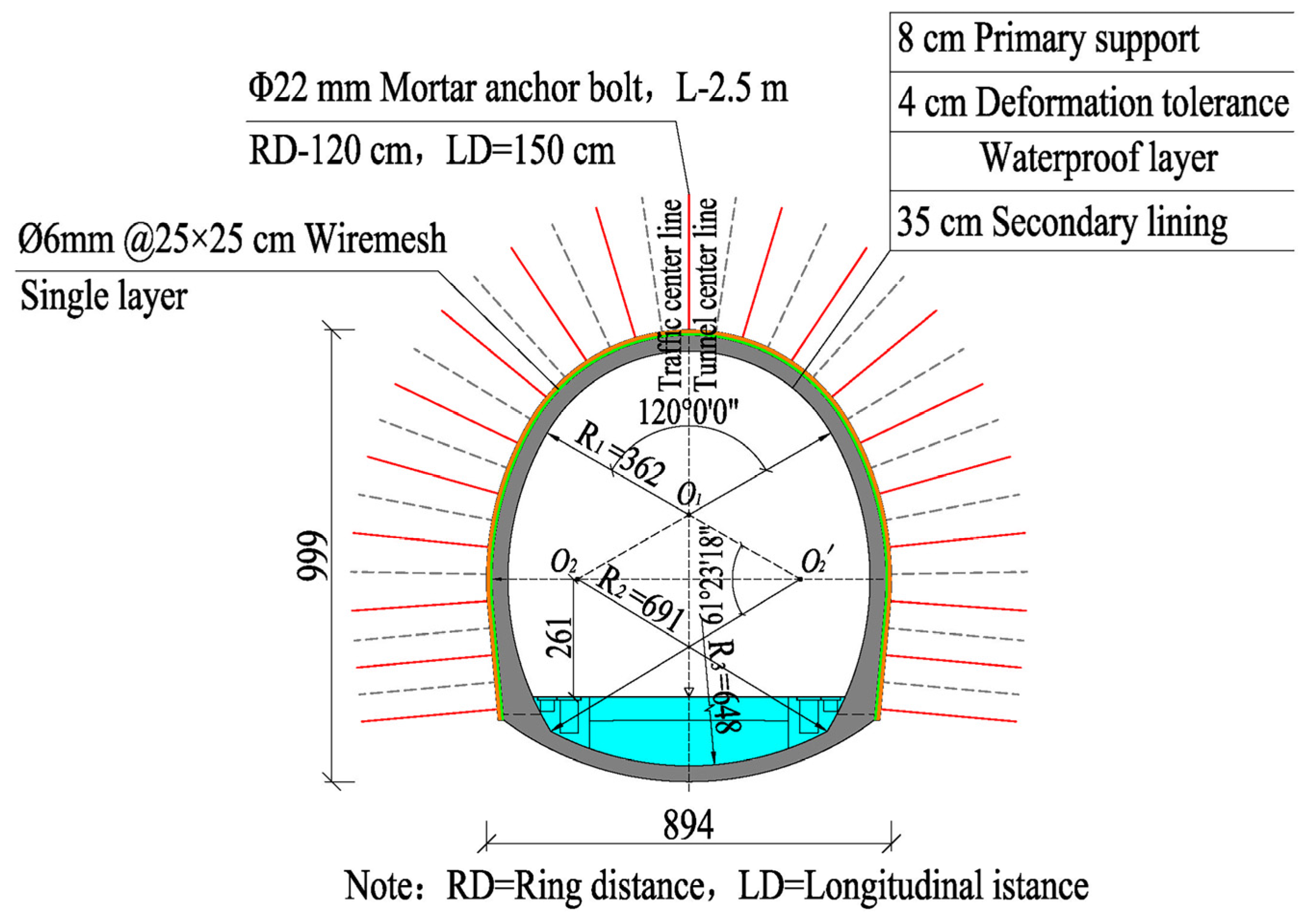
2.3. Tunnel Excavation and Support Design
3. Characteristics and Mechanisms of Large Deformation in Tunnels
3.1. Characteristics of Large Deformation
- (1)
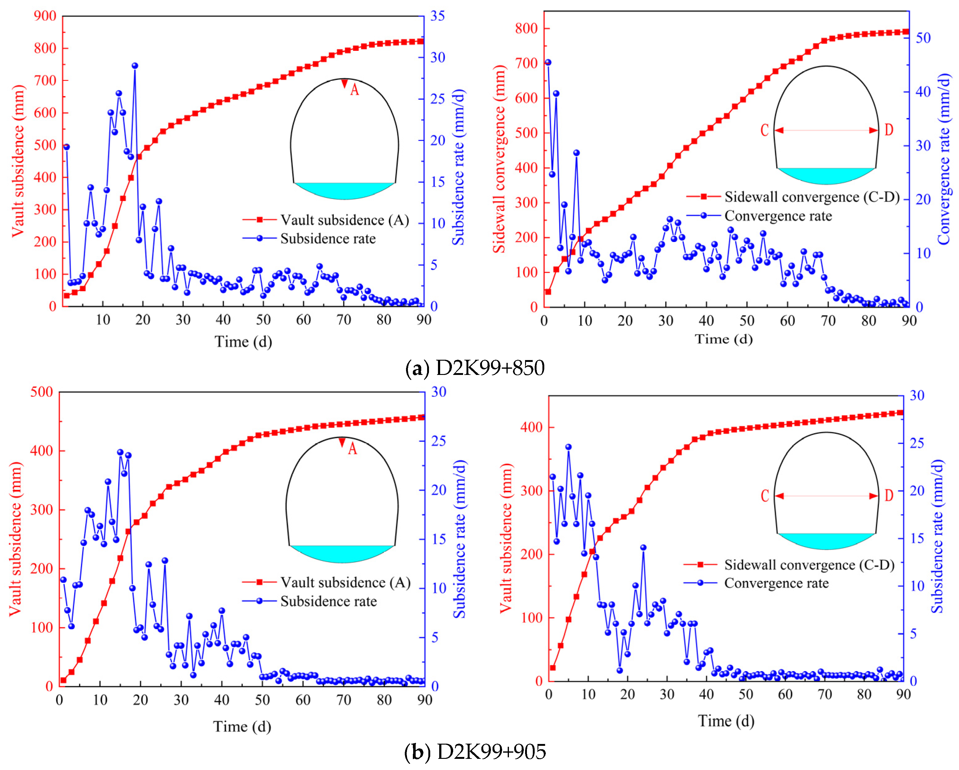
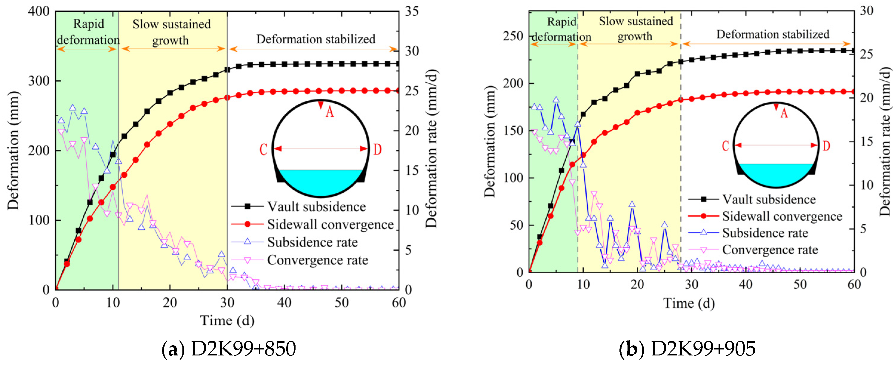
- Significant Deformation and Rate of Surrounding Rock: The results of the surrounding rock deformation monitoring curves are shown in Figure 5. As seen in Figure 5a, at section D2K99 + 850, the accumulated subsidence of the tunnel vault is 822.0 mm, with a maximum deformation rate of 50.8 mm/d. The accumulated convergence at the sidewall is 791.4 mm, with a maximum deformation rate of 44.5 mm/d. In Figure 5b, at section D2K99 + 905, the accumulated subsidence of the tunnel vault is 457.4 mm, with a maximum deformation rate of 23.8 mm/d, and the accumulated convergence at the sidewall is 423.3 mm, with a maximum deformation rate of 24.6 mm/d. The surrounding rock deformation at tunnel section D2K99 + 850 is severe, with a high deformation rate that has significantly exceeded the reserved deformation tolerance, severely encroaching the limits.
- (2)
- Long Duration of Surrounding Rock Deformation: The surrounding rock deformation in the section from D2K99 + 775 to D2K99 + 918 lasted long. After the initial support deformation occurred, the surrounding rock deformation did not stop immediately but continued to develop, exhibiting significant progressive and time-dependent effects. For instance, the surrounding rock deformation at section D2K99 + 850 lasted approximately 70 days before gradually stabilizing and converging.
- (3)
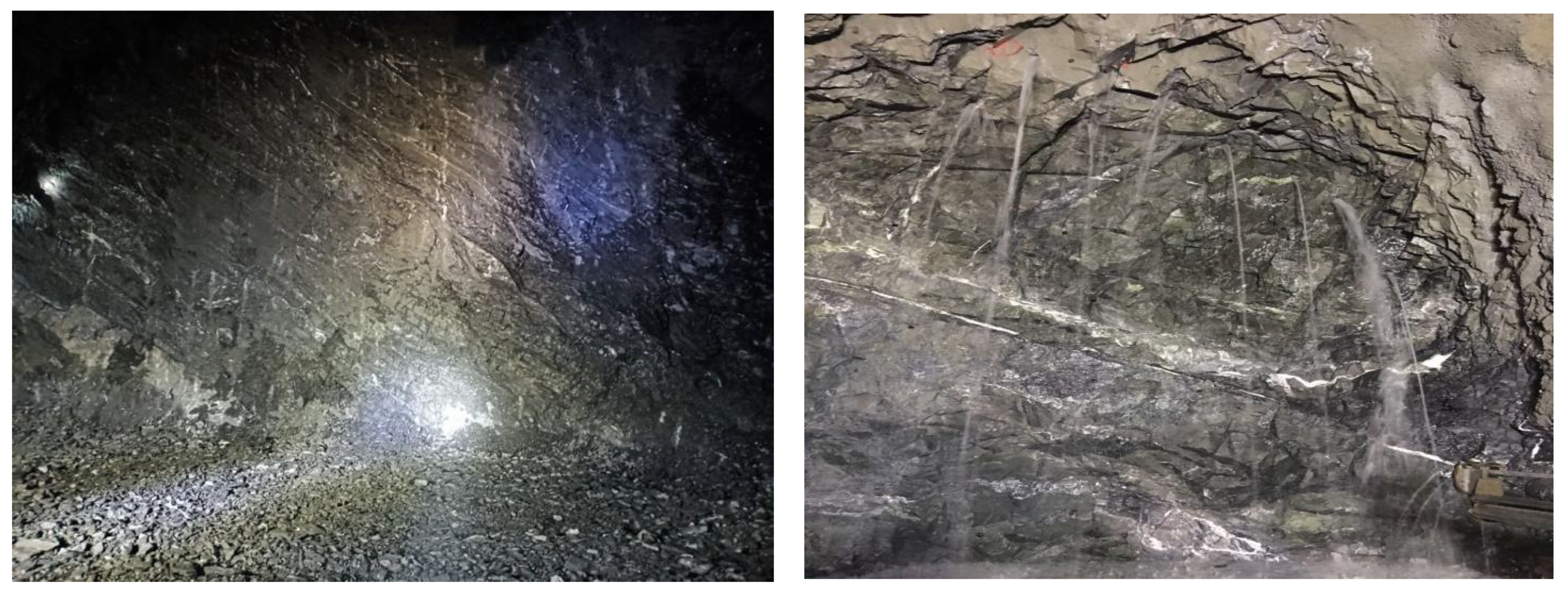
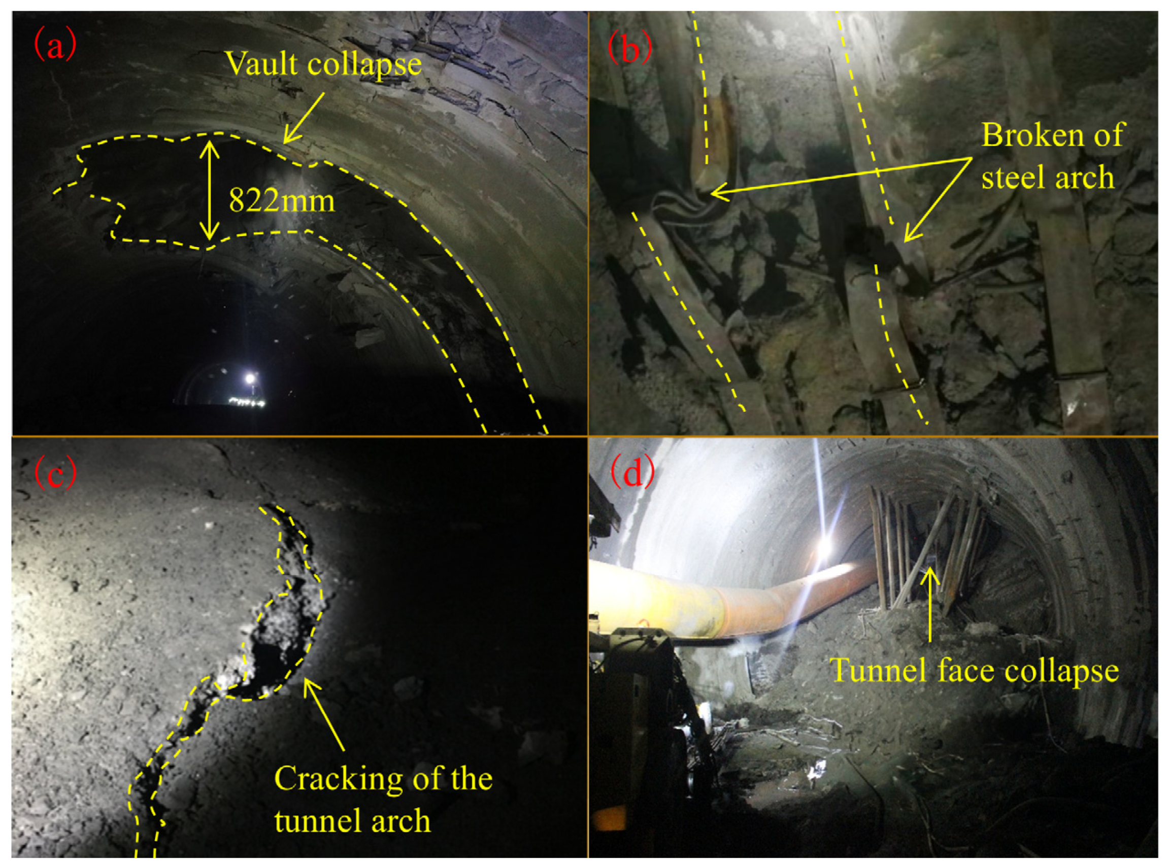
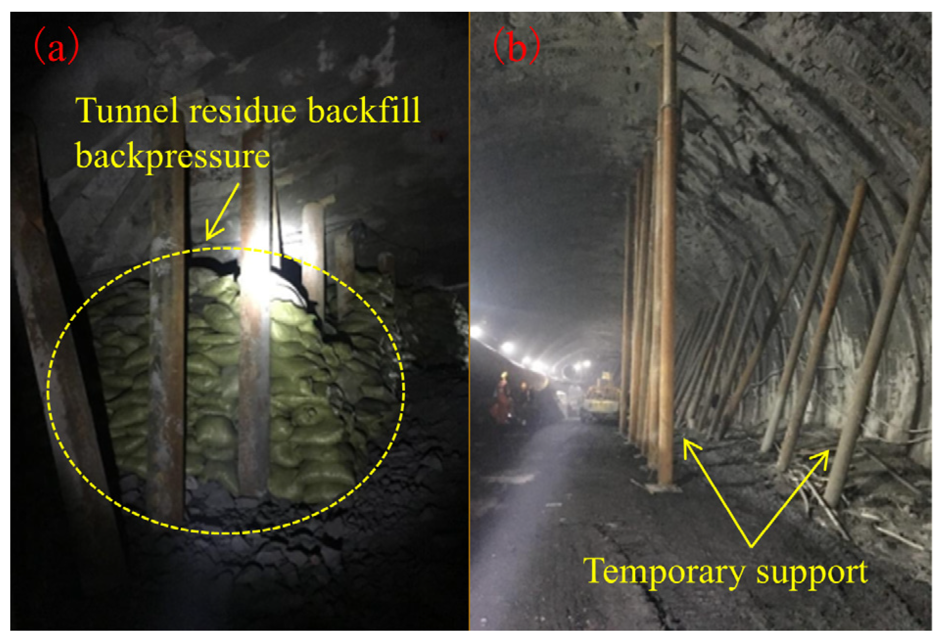
- Severe Deformation and Damage to Surrounding Rock: The surrounding rock in the section from D2K99 + 775 to D2K99 + 918 exhibited varying degrees of deformation and damage, primarily manifested as cracking of the sprayed concrete, spalling, and distortion or breakage of the steel framework. Among these, the deformation and damage at section D2K99 + 850 were the most severe, with signs of collapse. Over time, the deformation area from D2K99 + 775 to D2K99 + 918 gradually extended to the section from D2K99 + 700 to D2K99 + 941. According to on-site monitoring and measurement data, the initial support of the D2K99 + 700~D2K99 + 941 section is almost all infringed, which indicates that there is a significant safety risk in the subsequent construction of the tunnel, so it is necessary to dismantle and replace the initial support that has already been constructed, as shown in Figure 6.
3.2. Large Deformation Mechanism
- (1)
- Geological Structure
- (2)
- High Geostress
- (3)
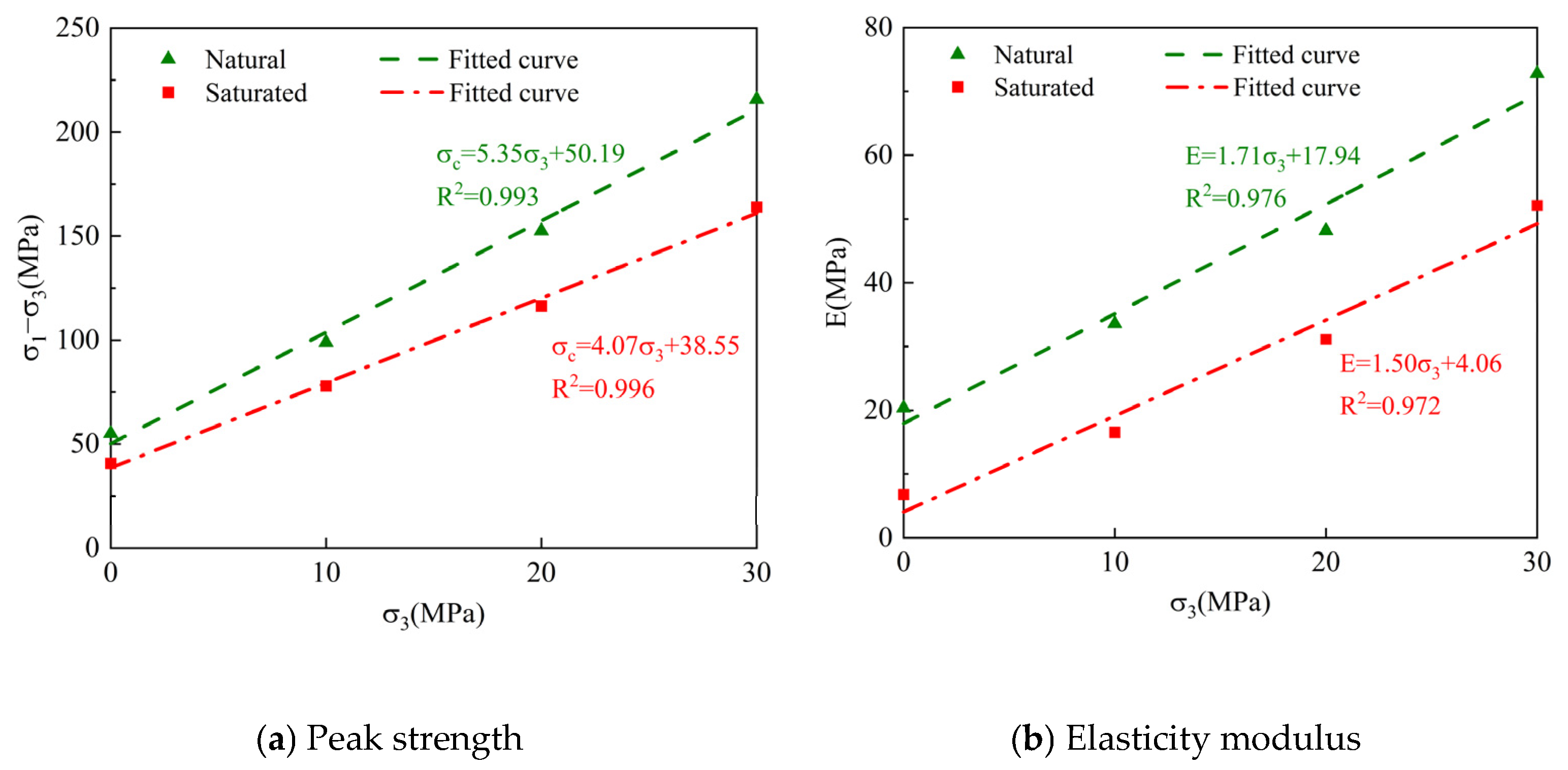
- Formation Lithology
- (4)
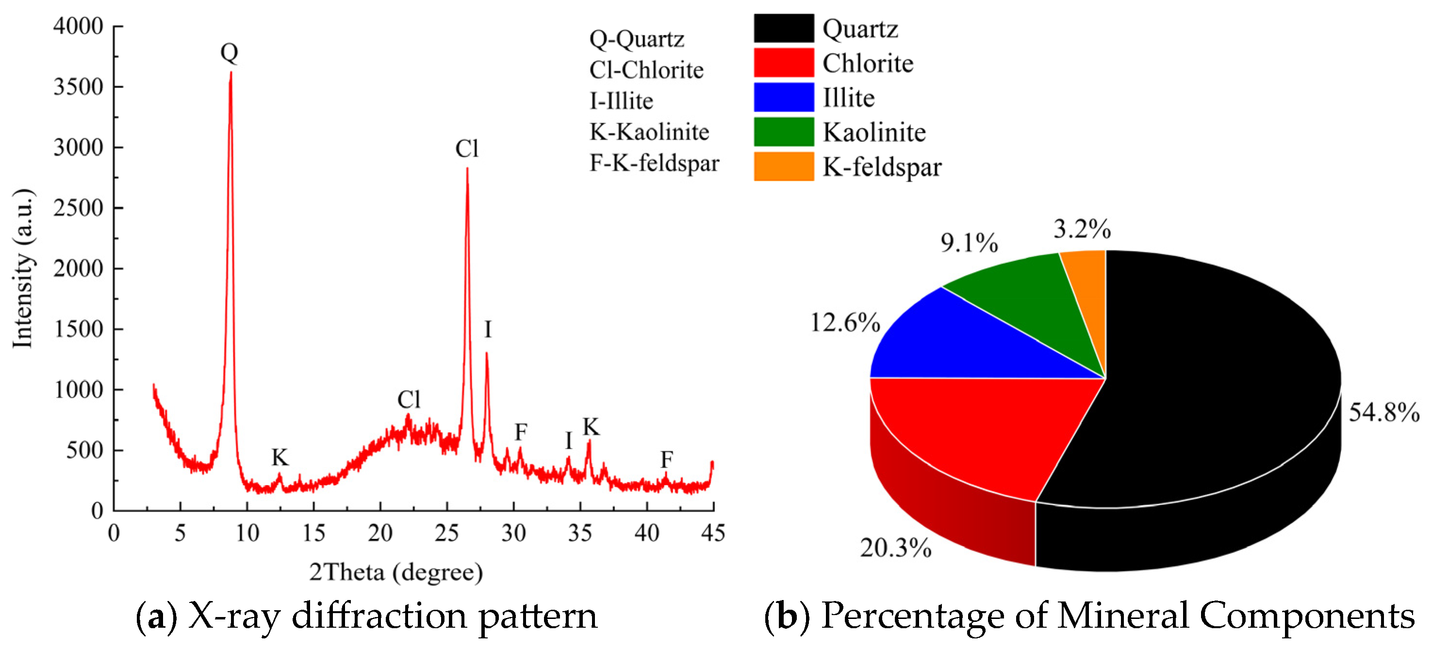
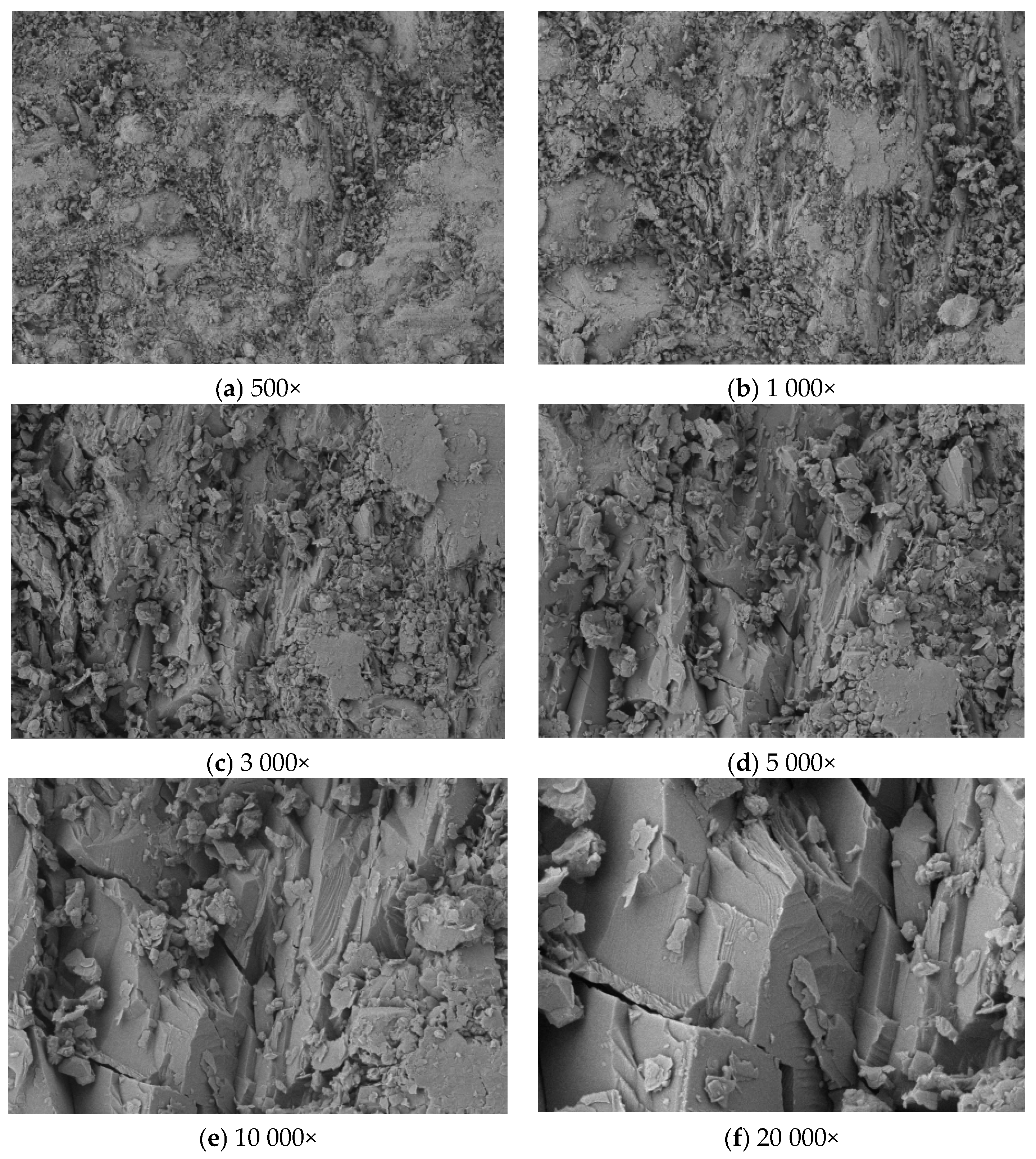
- Rock Mass Mineral Composition and Microstructure
- (5)
- Groundwater Influence
- (6)
- Impact of Human Factors
4. Tunnel Large Deformation Optimization Support Scheme
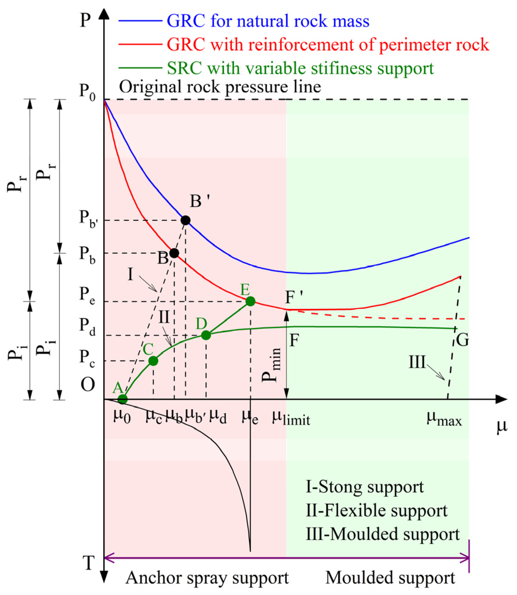
4.1. Active-Passive Cooperative Control Technology
- (1)
- Active support
- (2)
- Passive support
4.2. Tunnel Large Deformation Grading Control Program
- (1)
- For sections with slight deformation, use the Type I support scheme.
- (2)
- For sections with moderate deformation, use the Type II support scheme.
- (3)
- For sections with severe deformation, use the Type III support scheme.
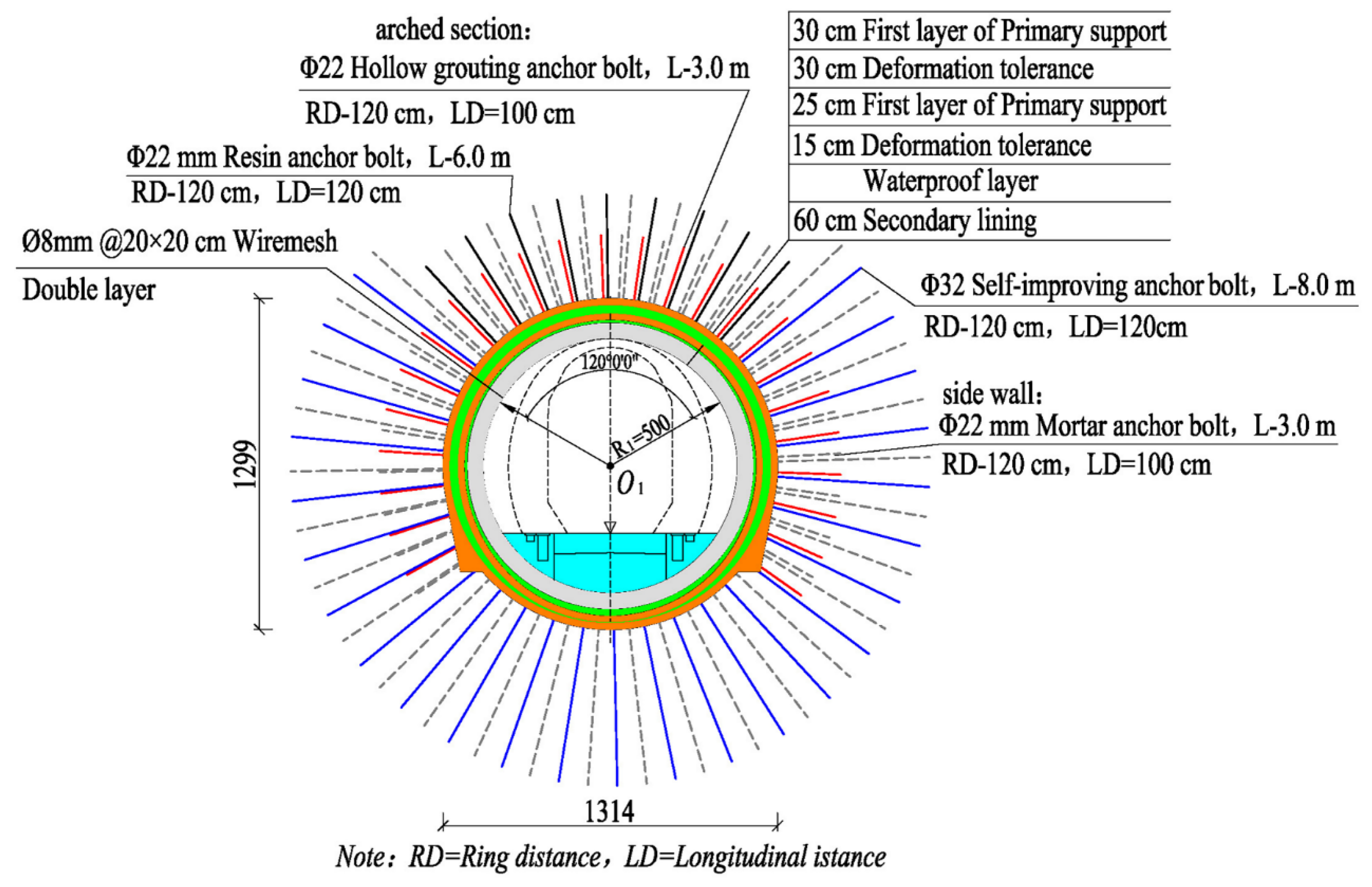
- (1)
- The Type I support scheme is shown in Figure 15.
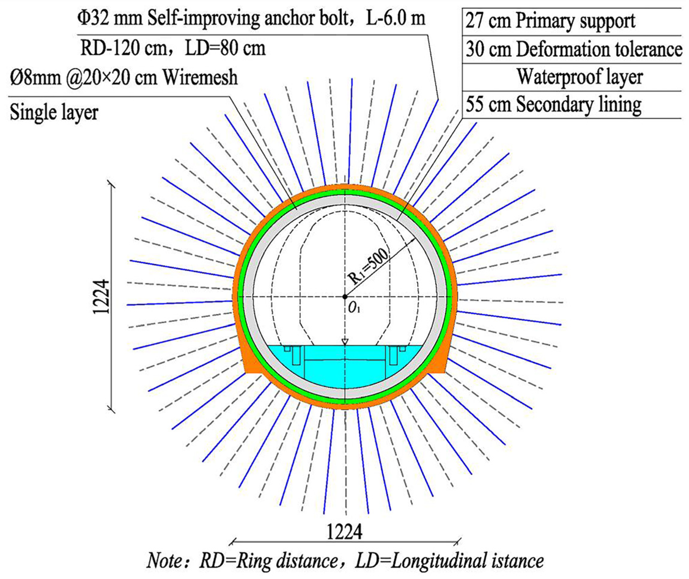
- (2)
- The Type II support scheme is shown in Figure 16.
- (3)
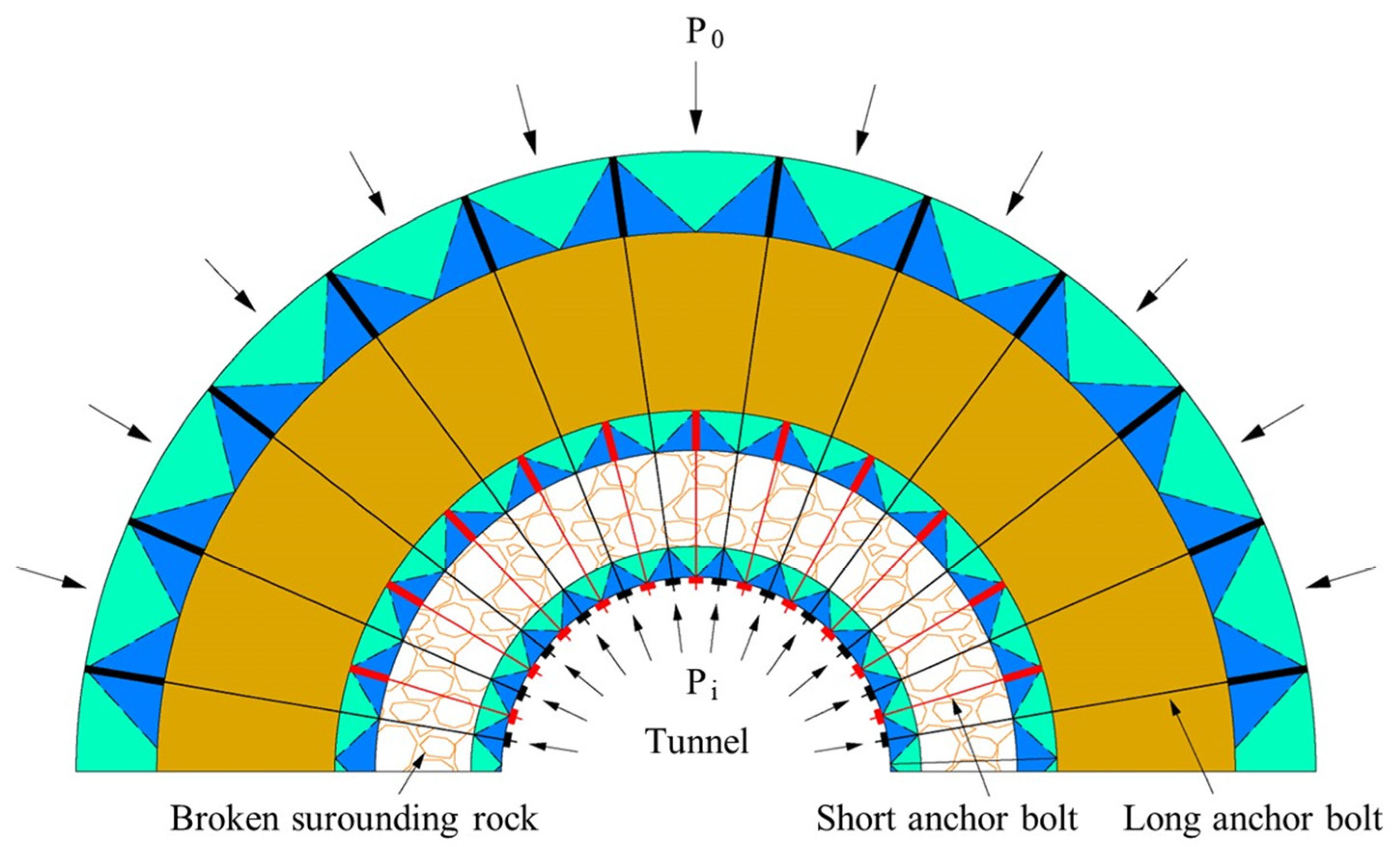
- Type III support scheme is shown in Figure 17.
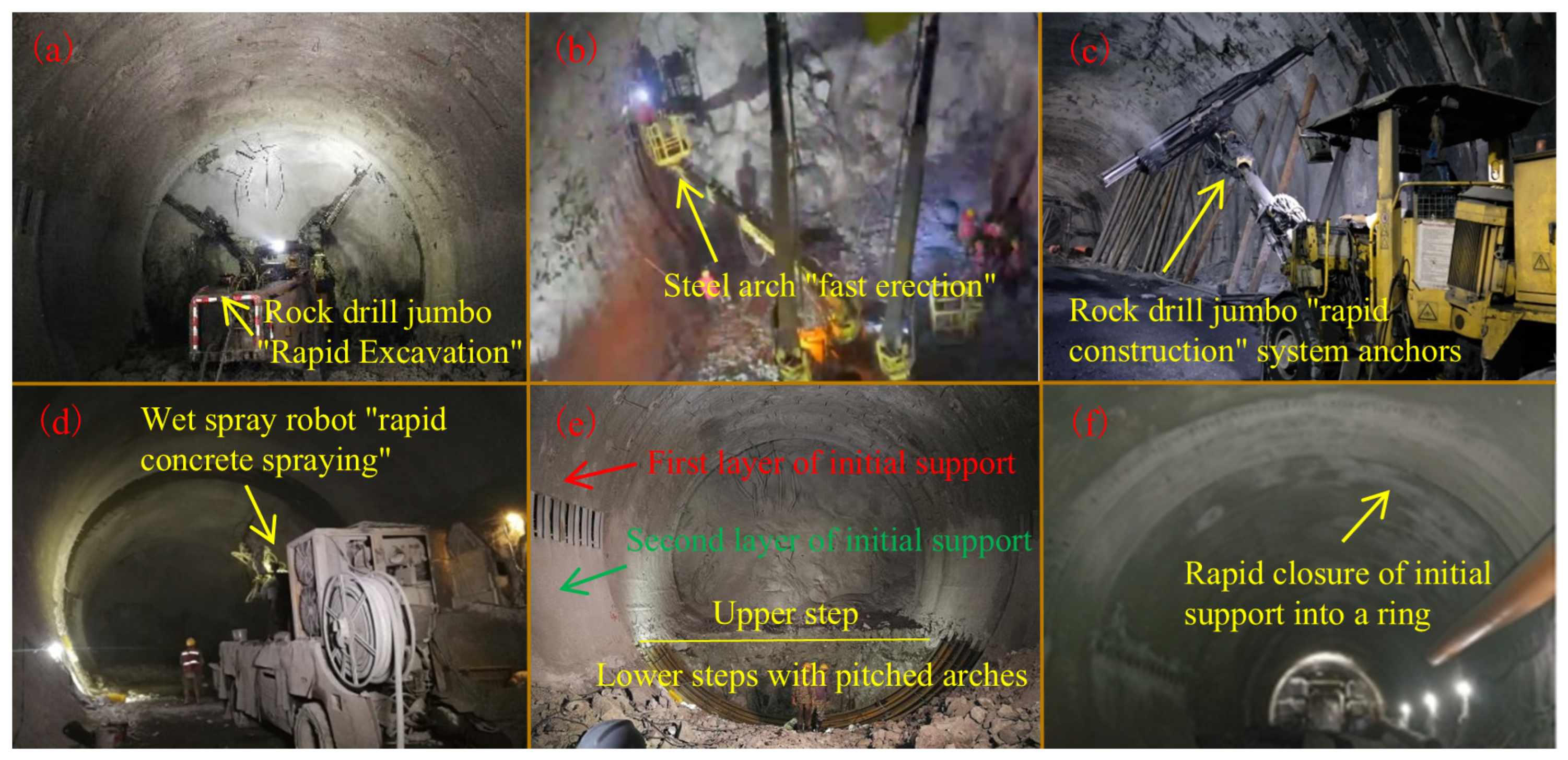
4.3. Construction Method
5. Verification of Countermeasures
6. Conclusions
- (1)
- Under the original support scheme, the deformation of tunnel peripheral rock has the characteristics of large deformation volume, large deformation rate and long duration. It is accompanied by the signs of sprayed concrete cracking, falling blocks, twisted and broken steel frames, and even peripheral rock collapse. These characteristics show that the traditional support method makes it difficult to effectively deal with the large deformation of high-geostress soft rock tunnels.
- (2)
- The large deformation of the tunnel’s surrounding rock is the result of a combination of factors such as high ground stress, ground lithology, geological structure, groundwater, and support scheme. High geostress and ground lithology are the main factors, while the presence of groundwater further weakens the mechanical properties of the surrounding rock and aggravates the development of deformation.
- (3)
- In terms of large deformation control, according to the different conditions of large deformation damage of surrounding rock, it is divided into three grades: severe large deformation, medium large deformation and slight large deformation, and corresponding support programs are designed for different grades to dynamically adapt to the deformation of surrounding rock and the “Mechanized construction method with two steps up and down” is also proposed, which ensures the safety of the construction process and realizes the mechanized construction method. Safety and effective control of mechanized construction.
- (4)
- The on-site monitoring results show that, after adopting the tunnel large deformation grading control scheme, the maximum values of arch settlement and peripheral convergence in section D2K99 + 850 (severely deformed section) and section D2K99 + 905 (moderately deformed section) have been reduced by 60.4%, 63.8%, 43.8%, and 43.3%, respectively, compared with that of the original support scheme. There is no abnormal deformation of the support structure. The maximum values of settlement and peripheral convergence were reduced by 60%, 63.8%, 43.3% and 43.3%, respectively, compared with the original support scheme, and there was no abnormal deformation of the support structure.
Author Contributions
Funding
Data Availability Statement
Conflicts of Interest
References
- Liu, D.X.; Huang, S.L.; Ding, X.L.; Chi, J.J.; Zhang, Y.T. Characteristics and Mechanism of Large Deformation of Tunnels in Tertiary Soft Rock: A Case Study. Buildings 2023, 13, 2262. [Google Scholar] [CrossRef]
- Zhang, B.J.; Tan, Z.S.; Zhao, J.P.; Wang, F.X.; Lin, K. Research on stress field inversion and large deformation level determination of super deep buried soft rock tunnel. Sci. Rep. 2024, 14, 12739. [Google Scholar] [CrossRef] [PubMed]
- Deng, H.S.; Fu, H.; Shi, Y.; Zhao, Y.Y.; Hou, W.Z. Countermeasures against large deformation of deep-buried soft rock tunnels in areas with high geostress: A case study. Tunn. Undergr. Space Technol. 2022, 119, 104238. [Google Scholar] [CrossRef]
- Arora, K.; Gutierrez, M.; Hedayat, A.; Cruz, E.C. Time-dependent behavior of the tunnels in squeezing ground: An experimental study. Rock Mech. Rock Eng. 2021, 54, 1755–1777. [Google Scholar] [CrossRef]
- Sun, Z.Y.; Zhang, D.L.; Li, M.Y.; Guo, F.L. Large Deformation Characteristics and the Countermeasures of a Deep-Buried Tunnel in Layered Shale under Groundwater. Tunn. Undergr. Space Technol. 2024, 144, 105575. [Google Scholar] [CrossRef]
- Sun, X.M.; Qi, Z.M.; Miao, C.Y.; Wang, J.; Zhang, J.X.; Jiang, M. Research on the large deformation mechanism and control measures of a layered soft rock tunnel. Bull. Eng. Geol. Environ. 2023, 82, 444. [Google Scholar] [CrossRef]
- Niu, Z.L.; Wang, Y.Q.; Fan, S.Y. Research on the deformation control of surrounding rock about large-section tunnel in strong-medium weathered slate. Front. Earth Sci. 2023, 10, 1094325. [Google Scholar] [CrossRef]
- Hu, Z.N.; Shen, J.; Wang, Y.F.; Guo, T.Z.; Liu, Z.C.; Gao, X.Q. Cracking characteristics and mechanism of entrance section in asymmetrically-load tunnel with bedded rock mass: A case study of a highway tunnel in southwest China. Eng. Fail. Anal. 2021, 122, 105221. [Google Scholar] [CrossRef]
- Agan, C. Prediction of squeezing potential of rock masses around the Suruc water tunnel. Bull. Eng. Geol. Environ. 2016, 75, 451–468. [Google Scholar] [CrossRef]
- Zhang, B.; Tao, Z.G.; Qiao, X.B.; Wang, Z.J. Study on large deformation mechanism and control technology of layered carbonaceous slate in deep tunnels. Bull. Eng. Geol. Environ. 2024, 83, 326. [Google Scholar] [CrossRef]
- Khanlari, G.; Meybodi, R.G.; Mokhtari, E. Engineering geological study of the second part of water supply Karaj to Tehran tunnel with emphasis on squeezing problems. Eng. Geol. 2012, 145, 9–17. [Google Scholar] [CrossRef]
- Fan, J.Y.; Guo, Z.B.; Qiao, X.B.; Tao, Z.G.; Wang, F.N. Constant resistance and yielding support technology for large deformations of surrounding rocks in the minxian tunnel. Adv. Civ. Eng. 2020, 2020, 8850686. [Google Scholar] [CrossRef]
- Zhao, J.P.; Tan, Z.S.; Li, Q.L.; Li, L. Characteristics and mechanism of large deformation of squeezing tunnel in phyllite stratum. Can. Geotech. J. 2023, 61, 59–74. [Google Scholar] [CrossRef]
- Xu, J.F.; Xie, X.Y.; Tang, G.J.; Zhou, B.; Xu, D.L.; Huang, Y. A new adaptive compressible element for tunnel lining support in squeezing rock masses. Tunn. Undergr. Space Technol. 2023, 137, 105124. [Google Scholar] [CrossRef]
- Zhang, G.S.; Xiao, M.L.; Zhang, Y.D.; Liu, H.Z.; Zhuo, L.; Xie, H.Q.; He, J.D. Experimental and numerical study on the mechanical properties of compressively precracked sandstone repaired by grouting. Constr. Build. Mater. 2022, 350, 128816. [Google Scholar] [CrossRef]
- Lu, H.F.; Zhang, Q.Z. Investigations on Shear Properties of Soft Rock Joints under Grouting. Rock Mech. Rock Eng. 2021, 54, 1875–1883. [Google Scholar] [CrossRef]
- Sun, C.H.; Li, Z.; Wu, J.; Wang, R.; Yang, X.; Liu, Y.Y. Research on Double-Layer Support Control for Large Deformation of Weak Surrounding Rock in Xiejiapo Tunnel. Buildings 2024, 14, 1371. [Google Scholar] [CrossRef]
- Li, L.; Lei, K. Research on Influence Factors of Bearing Capacity of Concrete-Filled Steel Tubular Arch for Traffic Tunnel. Symmetry 2022, 14, 167. [Google Scholar] [CrossRef]
- Chang, X.; Luo, X.L.; Liu, G.S. A Concrete-Filled Steel Tubular Yieldable Support for a Tunnel within Deep Soft Rock. Int. J. Geomech. 2022, 22, 04022093. [Google Scholar] [CrossRef]
- Wu, G.J.; Chen, W.Z.; Tian, H.M.; Jia, S.P.; Yang, J.P.; Tan, X.J. Numerical evaluation of a yielding tunnel lining support system used in limiting large deformation in squeezing rock. Environ. Earth Sci. 2018, 77, 439. [Google Scholar] [CrossRef]
- De La Fuente, M.; Taherzadeh, R.; Sulem, J.; Nguyen, X.S.; Subrin, D. Applicability of the convergence-confinement method to full-face excavation of circular tunnels with stiff support system. Rock Mech. Rock Eng. 2019, 52, 2361–2376. [Google Scholar] [CrossRef]
- Ghorbani, M.; Shahriar, K.; Sharifzadeh, M.; Masoudi, R. A critical review on the developments of rock support systems in high stress ground conditions. Int. J. Min. Sci. Technol. 2020, 30, 555–572. [Google Scholar] [CrossRef]
- Hu, X.Y.; Gutierrez, M. Viscoelastic Burger’s model for tunnels supported with tangentially yielding liner. J. Rock Mech. Geotech. Eng. 2023, 15, 826–837. [Google Scholar] [CrossRef]
- Liu, Y.; Qiu, W.E.; Duan, D.Y. Using energy-absorbing dampers to solve the problem of large deformation in soft-rock tunnels: A case study. Energies 2022, 15, 1916. [Google Scholar] [CrossRef]
- Rai, P.; Qiu, W.E.; Liu, Y.; Chen, J.H. A new experimental method of one single lining with airbag resistance limiter support for large deformation. Tunn. Undergr. Space Technol. 2024, 152, 105889. [Google Scholar] [CrossRef]
- He, M.C.; Wang, Q. Excavation compensation method and key technology for surrounding rock control. Eng. Geol. 2022, 307, 106784. [Google Scholar] [CrossRef]
- Tao, Z.G.; Xu, H.T.; Ren, S.L.; Guo, L.J.; Qin, K.; Zhu, Y.F. Negative Poisson’s ratio and peripheral strain of an NPR anchor cable. J. Mt. Sci. Eng. 2022, 19, 2435–2448. [Google Scholar] [CrossRef]
- Salazar, B.; Aghdasi, P.; Ostertag, C.P.; Taylor, H.K. Highly compressible concrete: The effect of reinforcement design on concrete’s compressive behavior at high strains. Mater. Des. 2023, 230, 111942. [Google Scholar] [CrossRef]
- Zhou, Z.H.; Xie, Q.M.; Chen, Z.Q.; Yao, Y.K.; Meng, W. Failure mechanism and stability identification of surrounding rock for soft-rock tunnels using long-footage rapid excavation method. Eng. Fail. Anal. 2024, 158, 108038. [Google Scholar] [CrossRef]
- Nie, J.C.; He, C.; Kou, H.; Liu, F.H.; Yang, W.B. Research on Excavation Method for Soft Rock Tunnel Based on Stress Release Rate. Appl. Sci. 2024, 14, 668. [Google Scholar] [CrossRef]
- GB/T 50218-2014; Standard for Classification of Engineering Rock Mass[S]. China Planning Press: Beijing, China, 2014.
- Hoek, E.; Marinos, P. Estimating thegeotechnical properties of heteroge-neous rock masses such as flysch. Bull. Eng. Geol. Environ. 2001, 60, 82–92. [Google Scholar]
- Dai, Z.W.; Wang, L.Q.; Zhang, K.Q.; Wang, L.; Gao, X.C. Implementation of the Barton–Bandis Nonlinear Strength Criterion into Mohr–Coulomb Sliding Failure Model. Adv. Mater. Sci. Eng. 2022, 2022, 1590884. [Google Scholar] [CrossRef]
- Savvides, A.A.; Antoniou, A.A.; Papadopoulos, L.; Monia, A.; Kofina, K. An estimation of clayey-oriented rock mass material properties, sited in Koropi, Athens, Greece, through feed-forward neural networks. Geotechnics 2023, 3, 975–988. [Google Scholar] [CrossRef]
- Bian, K.; Liu, J.; Liu, Z.P.; Liu, S.G.; Ai, F.; Zheng, X.Q.; Ni, S.H.; Zhang, W. Mechanisms of large deformation in soft rock tunnels: A case study of Huangjiazhai Tunnel. Bull. Eng. Geol. Environ. 2019, 78, 431–444. [Google Scholar] [CrossRef]
- Li, X.B.; Wu, Y.C.; Huang, L.Q. Mechanical behavior and thermal damage characterization of granite after flame jet-water cooling treatment. Int. J. Min. Sci. Technol. 2024, 180, 105833. [Google Scholar] [CrossRef]
- Wei, J.; Zhou, J.; Liang, Y.; Jin, R.C.; Jing, L.W. Deformation and failure mechanism of surrounding rock in deep soft rock tunnels considering rock rheology and different strength criteria. Rock Mech. Rock Eng. 2024, 57, 545–580. [Google Scholar] [CrossRef]
- Adhikari, A.; Roy, N. Generalized Ground Reaction and Longitudinal Deformation Curves for Circular Tunnels in Rock Mass. Transp. Infrastruct. Geotech. 2023, 11, 2046–2068. [Google Scholar] [CrossRef]
- Xu, C.; Xia, C.C.; Han, C.L. Modified ground response curve (grc) in strain-softening rock mass based on the generalized zhang-zhu strength criterion considering over-excavation. Undergr. Space. 2021, 6, 585–602. [Google Scholar] [CrossRef]
- Wei, Y.; Wang, B.; Xin, Z.; Guo, X.X.; Wang, Z.Y. Effect of prestressed anchorage system on mechanical behavior of squeezed soft rock in large-deformation tunnel. Tunn. Undergr. Space Technol. 2023, 131, 104782. [Google Scholar] [CrossRef]
- Zhao, J.P.; Tan, Z.S.; Wang, W.X.; Yu, R.S.; Wang, J.J.; Li, Z.L. 2023. Study on the large deformation control technology of a single-hole double-track railway tunnel. Bull. Eng. Geol. Environ. 2023, 82, 343. [Google Scholar] [CrossRef]


| Items | Primary Support | Secondary Lining | Ancillary Construction Measures | |||
|---|---|---|---|---|---|---|
| System Bolt | Wiremesh | Shotcrete | Deformation Tolerance | |||
| III surrounding rock | Φ22 mm × 2.5 m Mortar bolt (@1.2 × 1.5 m) | Single-layer Φ6 × Φ6 (@20 × 20 cm) | C25 Concrete 8 cm | 3~4 cm | C30 Concrete 35 cm | Φ42 advance small pipe @35 mm × 300 mm |
| Test Position Depth (m) | Maximum Horizontal Principal Stress (MPa) | Minimum Horizontal Principal Stress (MPa) | Vertical Stress (MPa) | Direction of Maximum Horizontal Principal Stress |
|---|---|---|---|---|
| 29.1 | 24.62 | 13.69 | 27.76 | N35.0°E |
| 27.9 | 21.49 | 11.67 | 27.73 | |
| 26.8 | 20.38 | 10.83 | 27.70 | |
| 25.7 | 20.17 | 10.61 | 27.67 | N14.7°E |
| 23.2 | 19.62 | 10.32 | 27.60 | N43.5°E |
| Start and Ending Mileage | Length (m) | Working Drawing | Dynamic Design | ||
|---|---|---|---|---|---|
| Surrounding Rock Level | Deformation | Surrounding Rock Level | Support Measures | ||
| D2K99 + 700~ + 892 | 192 | Class III | severity | Class V | Circular section, long and short anchors + grouting, double-layer initial support |
| D2K99 + 892~ + 918 | 26 | medium | Class V | Circular section, plain composite lining, single layer initial support | |
| D2K99 + 918~ + 941 | 23 | minimal | Class IV | Ordinary composite lining, single-layer initial support | |
Disclaimer/Publisher’s Note: The statements, opinions and data contained in all publications are solely those of the individual author(s) and contributor(s) and not of MDPI and/or the editor(s). MDPI and/or the editor(s) disclaim responsibility for any injury to people or property resulting from any ideas, methods, instructions or products referred to in the content. |
© 2025 by the authors. Licensee MDPI, Basel, Switzerland. This article is an open access article distributed under the terms and conditions of the Creative Commons Attribution (CC BY) license (https://creativecommons.org/licenses/by/4.0/).
Share and Cite
Chen, L.; Xi, B.; Zhao, N.; He, S.; Dong, Y.; Liu, K.; Gao, P.; Liu, G. Large Deformation Mechanism and Support Countermeasures of Deep-Buried Soft Rock Tunnels Under High Geostress State. Buildings 2025, 15, 704. https://doi.org/10.3390/buildings15050704
Chen L, Xi B, Zhao N, He S, Dong Y, Liu K, Gao P, Liu G. Large Deformation Mechanism and Support Countermeasures of Deep-Buried Soft Rock Tunnels Under High Geostress State. Buildings. 2025; 15(5):704. https://doi.org/10.3390/buildings15050704
Chicago/Turabian StyleChen, Luhai, Baoping Xi, Na Zhao, Shuixin He, Yunsheng Dong, Keliu Liu, Pengli Gao, and Guoqiang Liu. 2025. "Large Deformation Mechanism and Support Countermeasures of Deep-Buried Soft Rock Tunnels Under High Geostress State" Buildings 15, no. 5: 704. https://doi.org/10.3390/buildings15050704
APA StyleChen, L., Xi, B., Zhao, N., He, S., Dong, Y., Liu, K., Gao, P., & Liu, G. (2025). Large Deformation Mechanism and Support Countermeasures of Deep-Buried Soft Rock Tunnels Under High Geostress State. Buildings, 15(5), 704. https://doi.org/10.3390/buildings15050704