
Local Full-Scale Model Test on Mechanical Performance of the Integral Splicing Composite Structure of Adjacent Existing Box Girder Bridges


Abstract
1. Introduction
2. Background
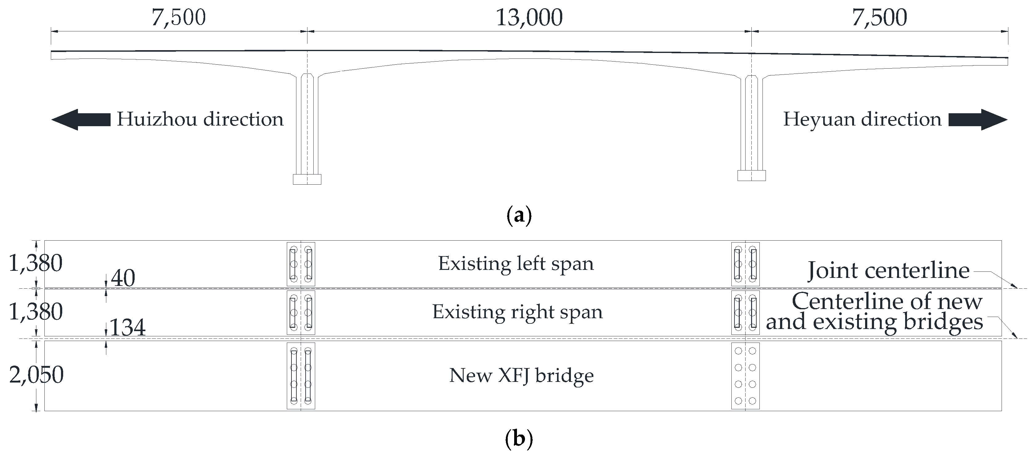
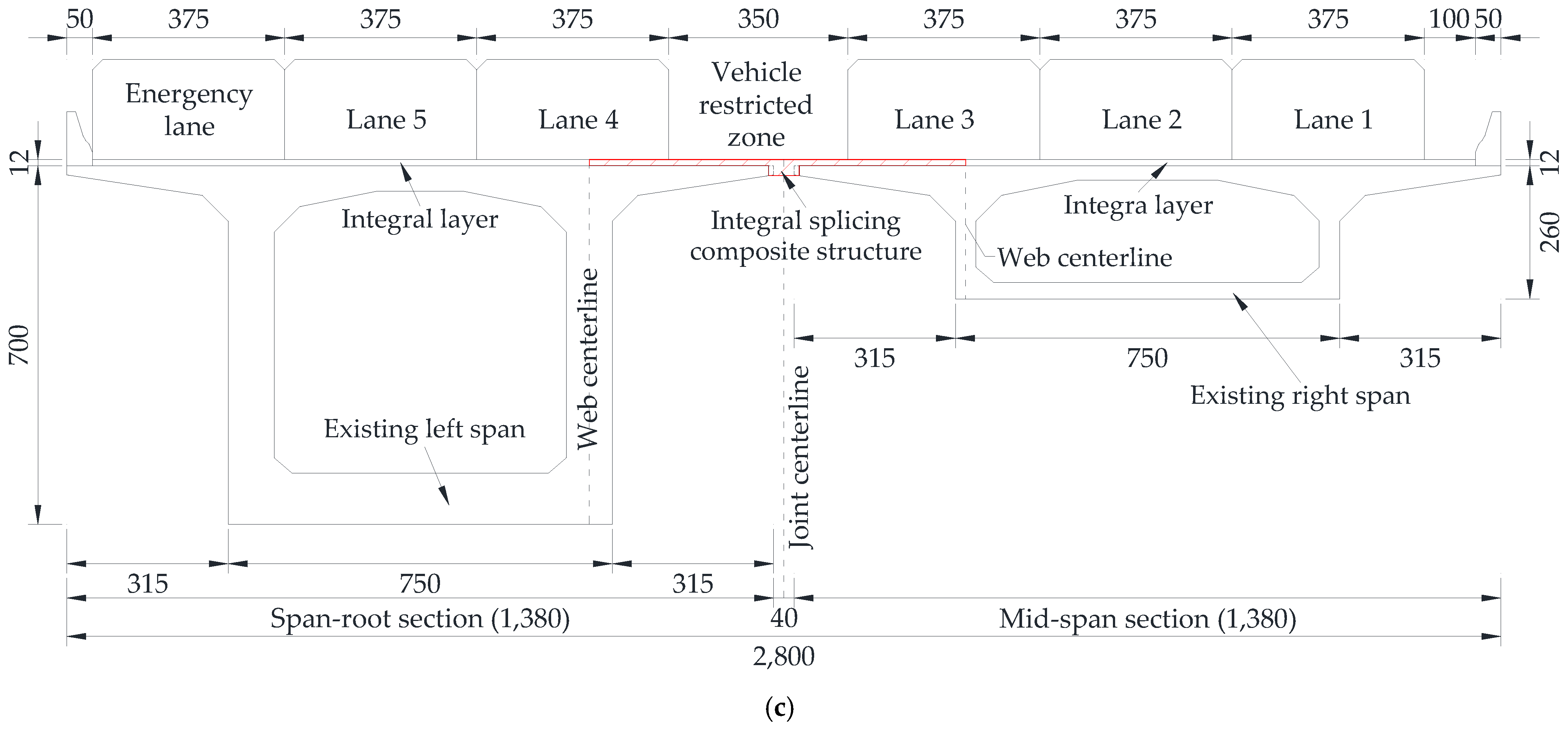
2.1. Target Box Girder Bridge
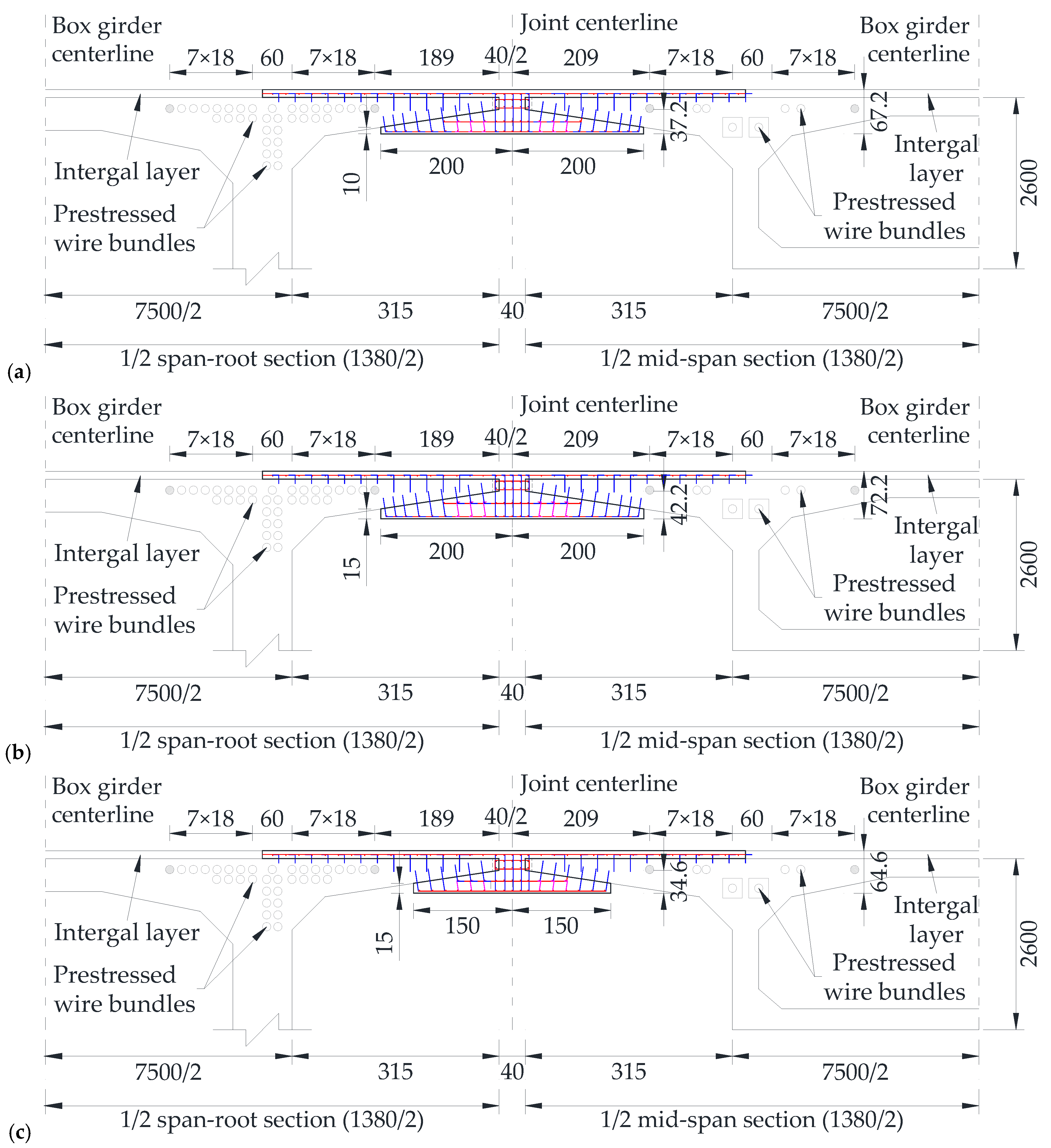
2.2. Integral Splicing Scheme of Adjacent Flange Plates
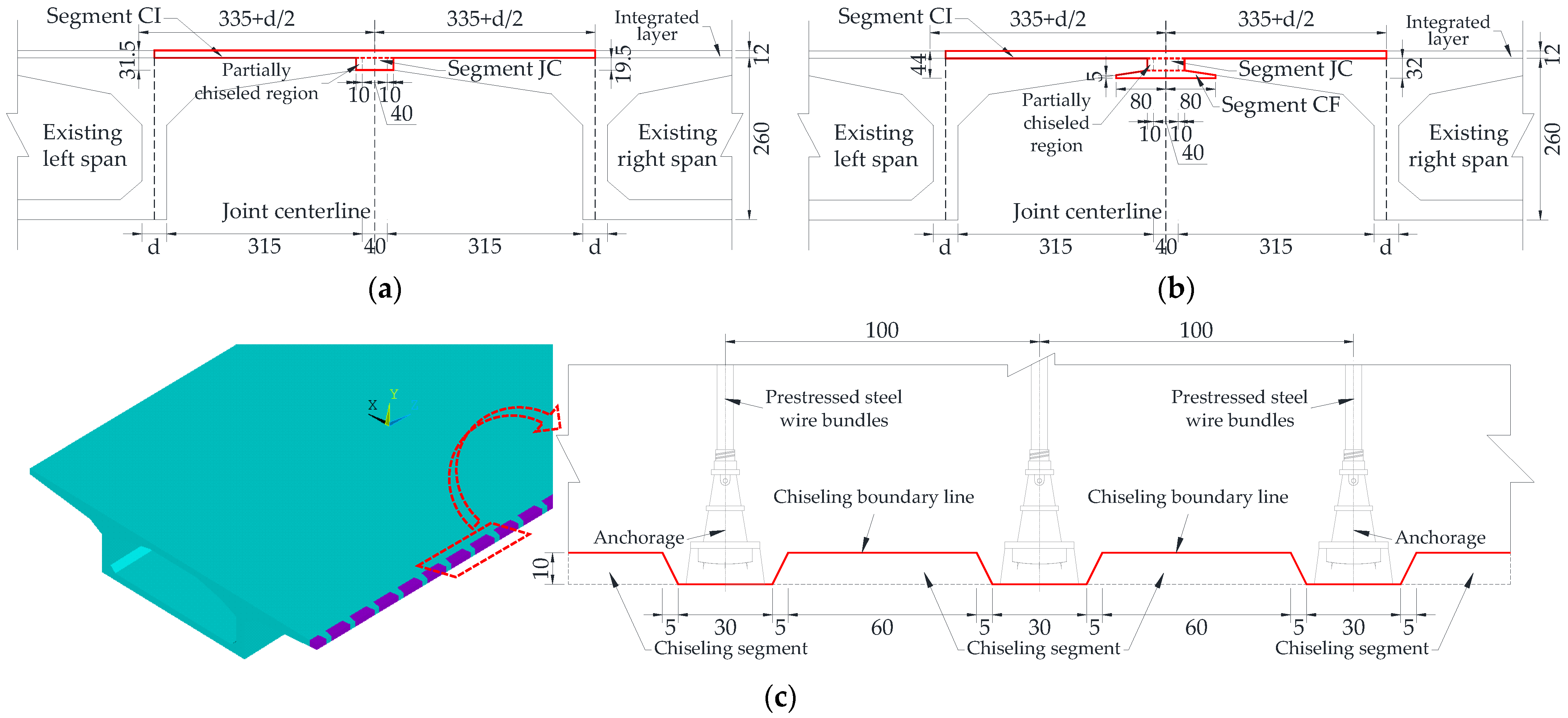
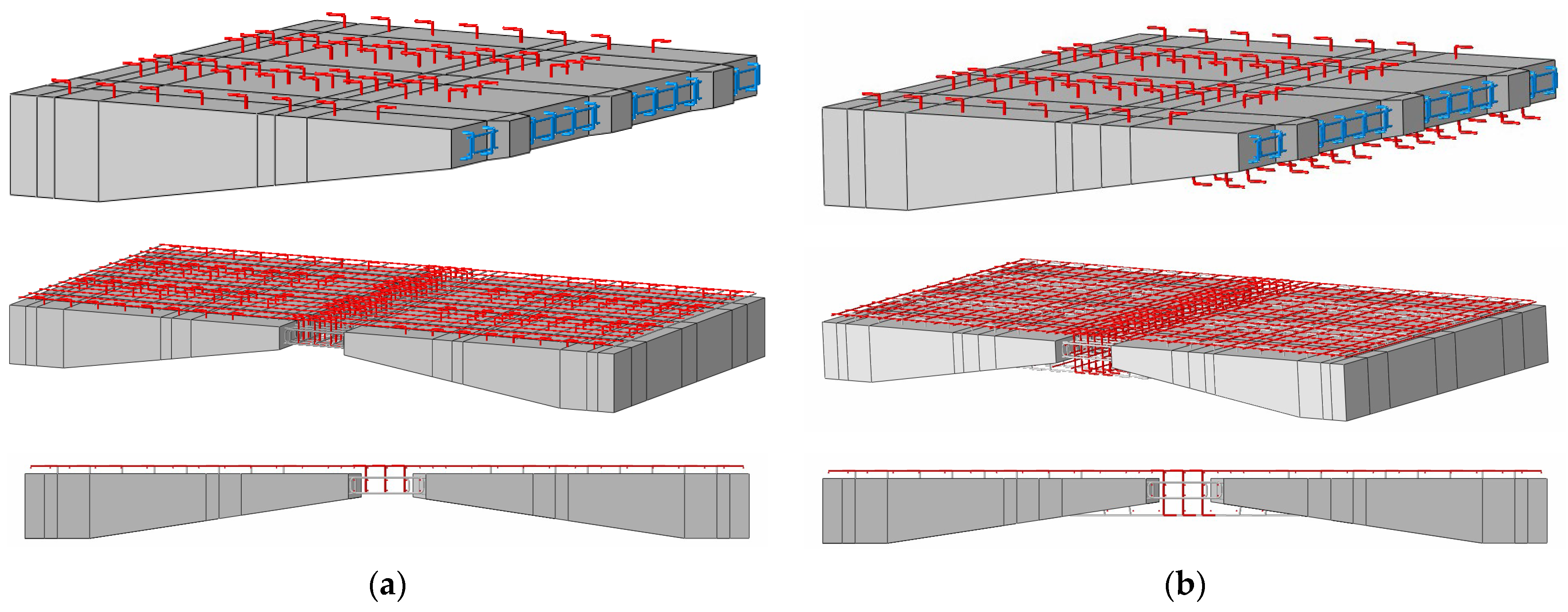
- Scheme ZL: The adjacent flange plate ends are directly connected by the splicing region. The thickness of the splicing region is the same as that of the flange plate ends, as shown in Figure 2a.
- Scheme ZH: The adjacent flange plate ends are connected by a thickened splicing region, and part of the flange plate end is wrapped, as shown in Figure 2b.
3. Test Design
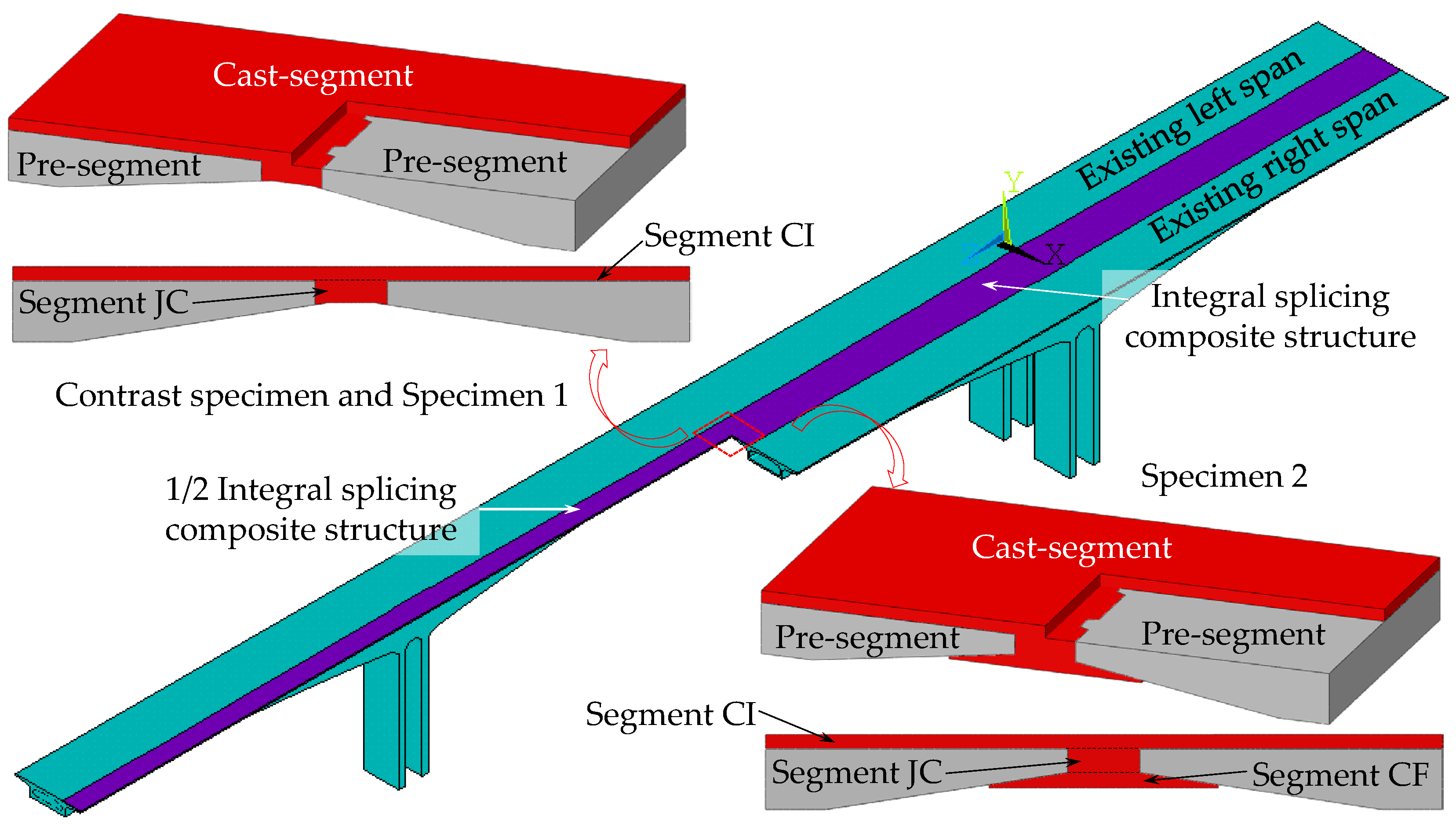
3.1. Design of Local Full-Scale Specimen
3.1.1. Specimen Size
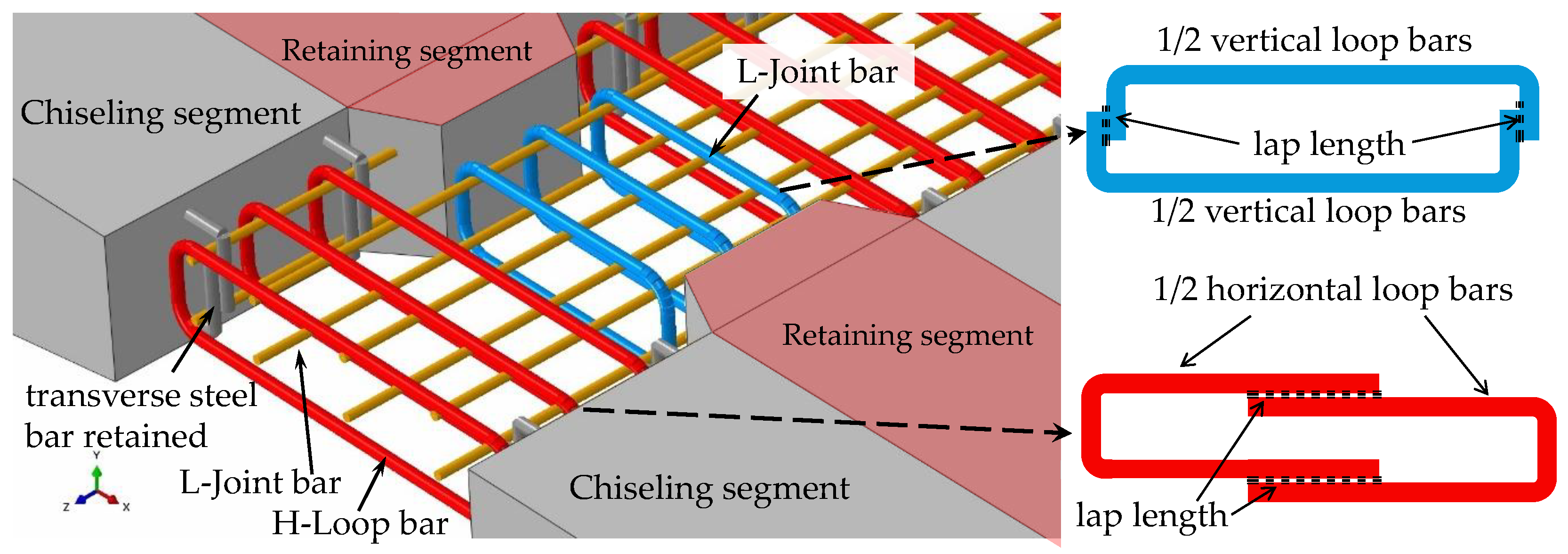
3.1.2. Steel Bar Arrangement Form of Cast-Segment
- Joint connection segment (segment JC)
- 2.
- Composite segment as an integral layer (segment CI)
- 3.
- Composite segment below the flange plate (segment CF)
3.1.3. Material Composition and Properties
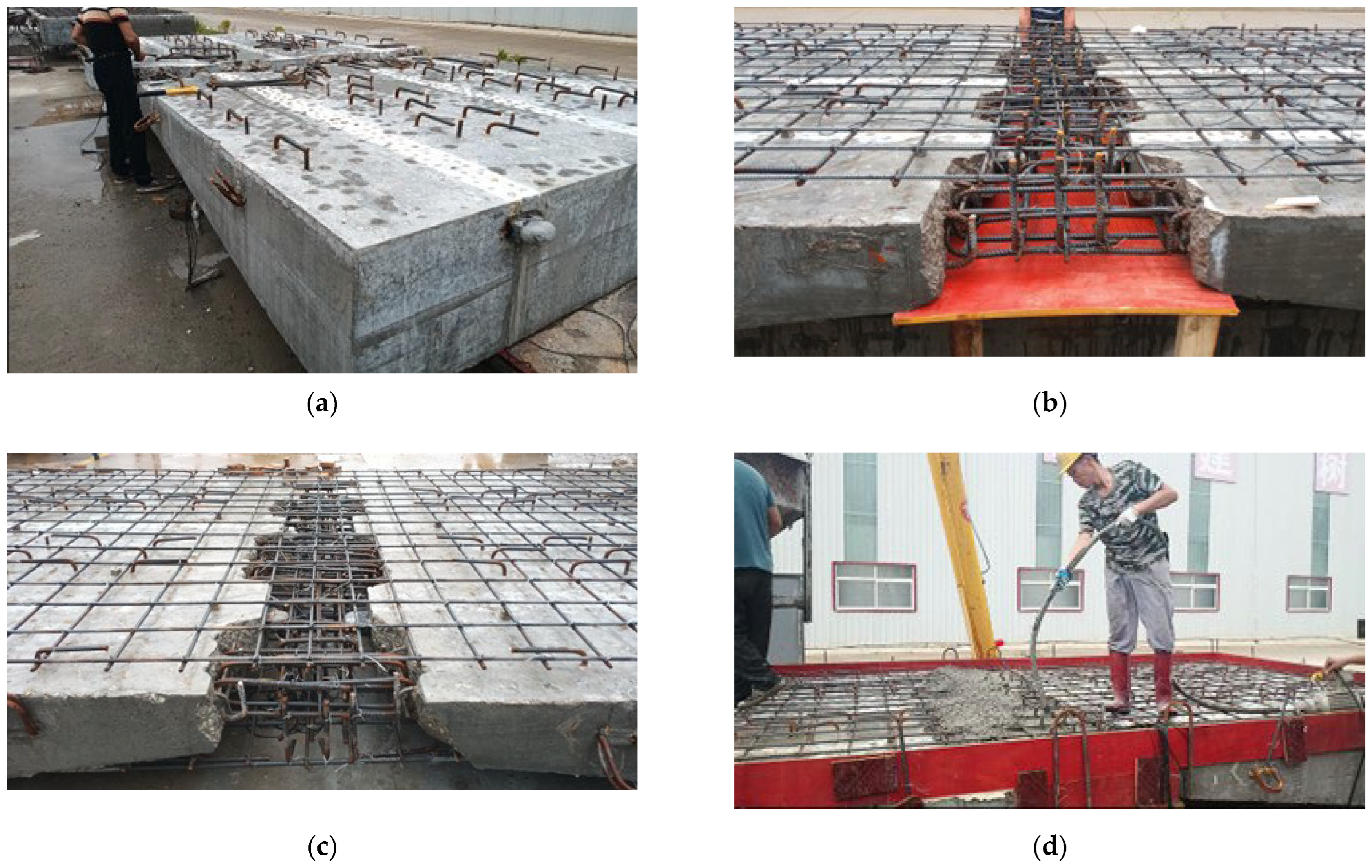
3.2. Preparation Process of Specimens
3.2.1. Preparation of Prefabricated Segments
3.2.2. Concrete Chiseling at the Splicing End
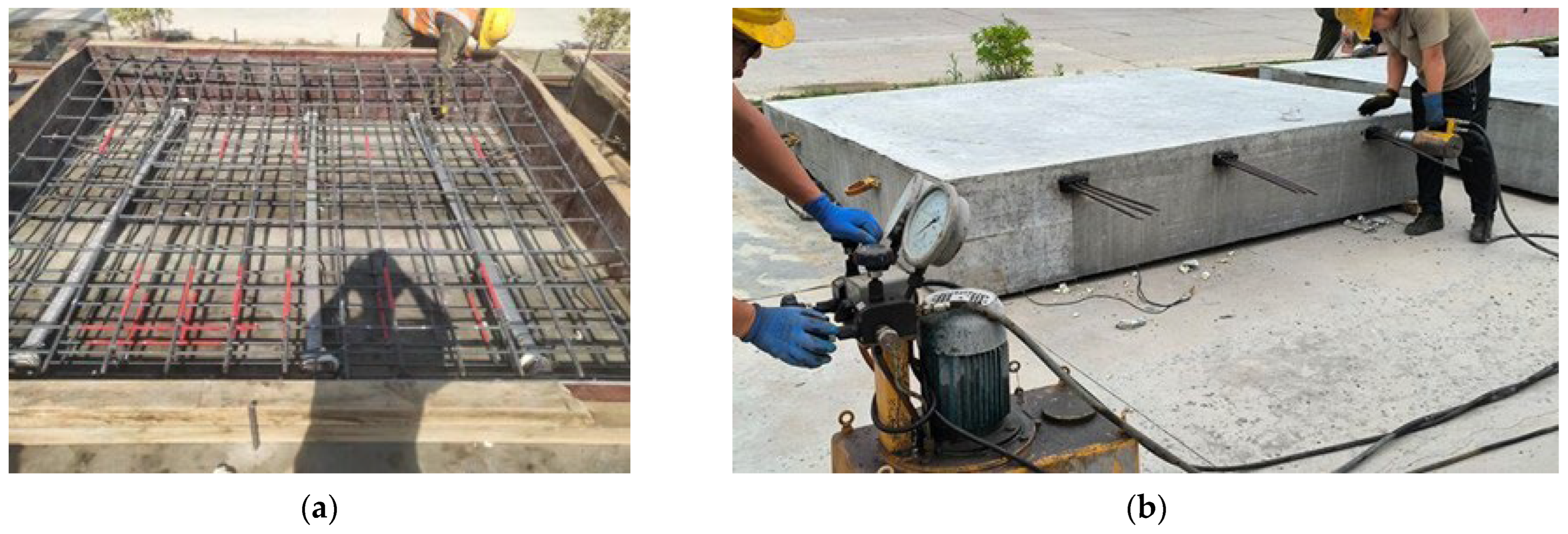
3.2.3. Reinforcement Connection and Concrete Pouring in the Splicing Region
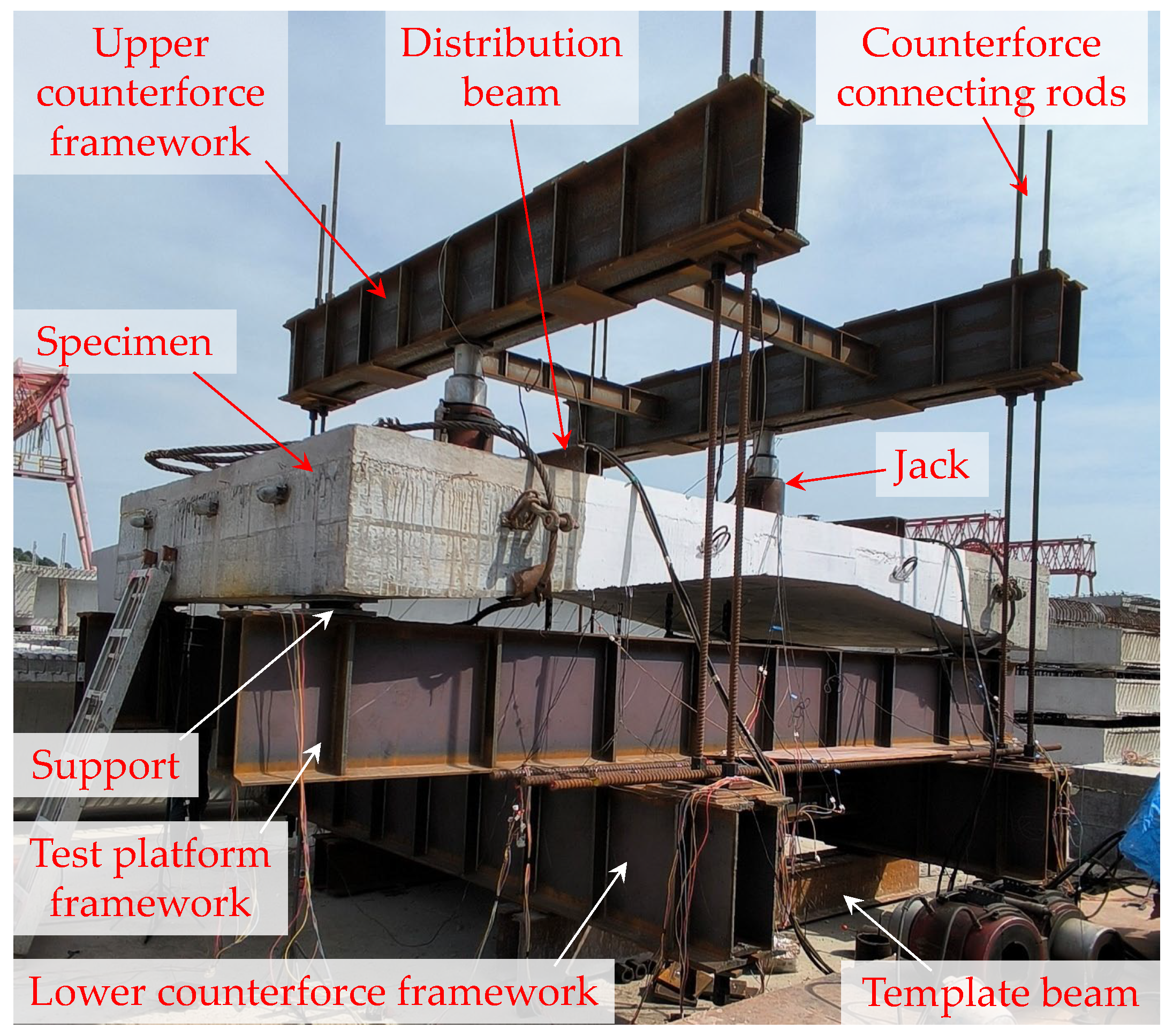
3.3. Test Setup
3.3.1. Loading Setup
- Upper counterforce framework: composed of two 4.5 m double-splicing I-shaped steel beams of I63 and two 2.4 m I-shaped steel beams of I20a.
- Test platform framework: composed of two 6.0 m double-splicing I-shaped steel beams of I63 and two 2.0 m I-shaped steel beams of I20a.
- Lower counterforce framework: composed of two 4.5 m double-splicing I-shaped steel beams of I56 and two 2.4 m I-shaped steel beams of I20a.
- The steel grade of these frames is Q235.
- Counterforce connecting rods: composed of eight thread steel rods of PSB930 with a diameter of 40 mm.
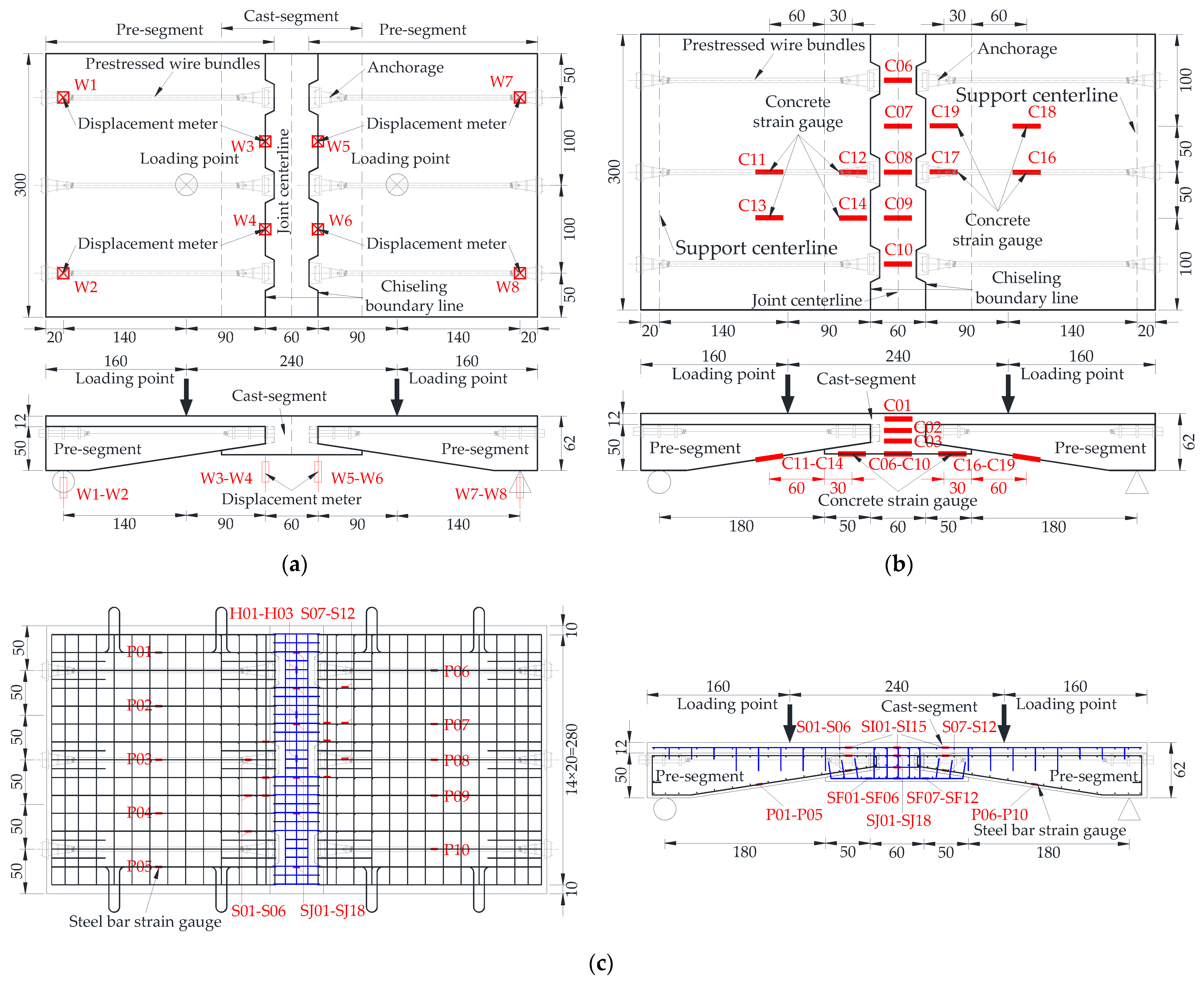
3.3.2. Measurement Setup
- Measurement of loading force
- Measurement of displacement
- Measurement of concrete strain
- Measurement of steel bar strain
4. Test Results and Analysis
4.1. Crack Propagation Characteristics and Failure Mode
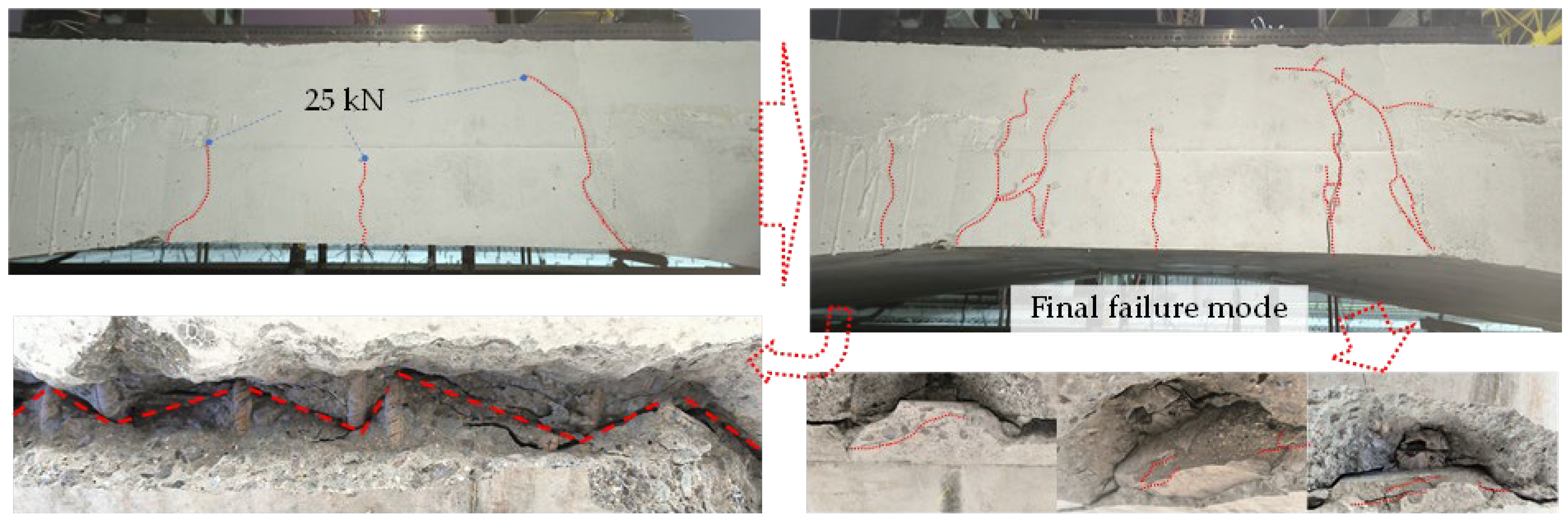
4.1.1. Contrast Specimen
- Crack Propagation Characteristics
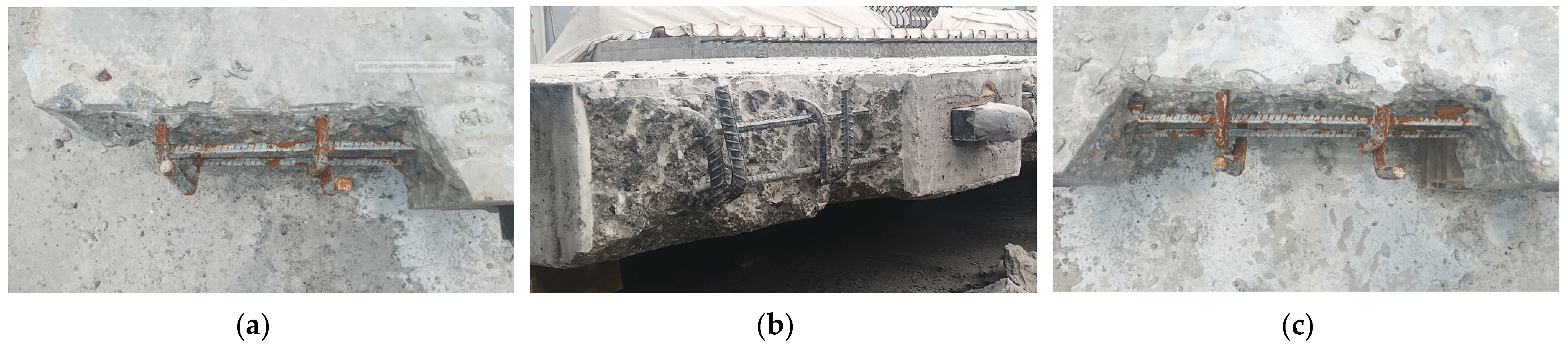
- Final failure mode
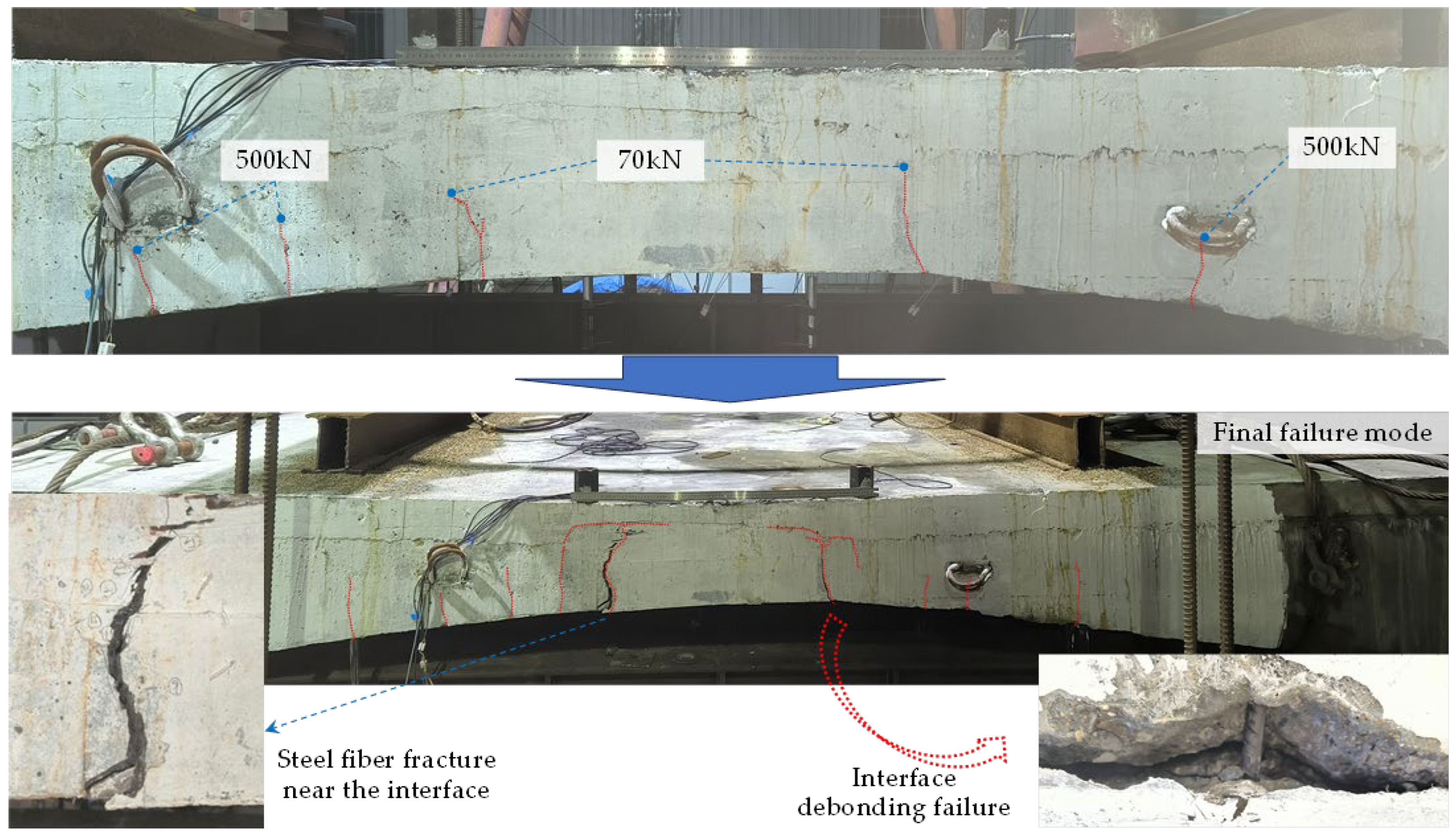
4.1.2. Specimen 1
- Crack Propagation Characteristics
- Final failure mode
4.1.3. Specimen 2
- Crack Propagation Characteristics
- Final failure mode
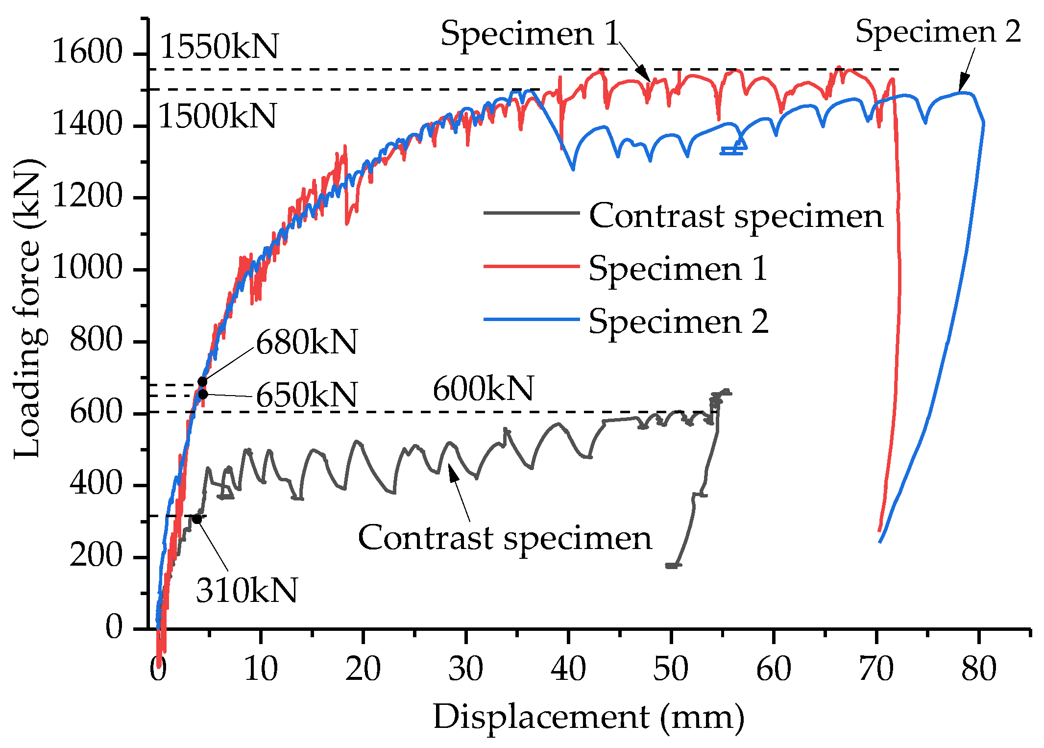
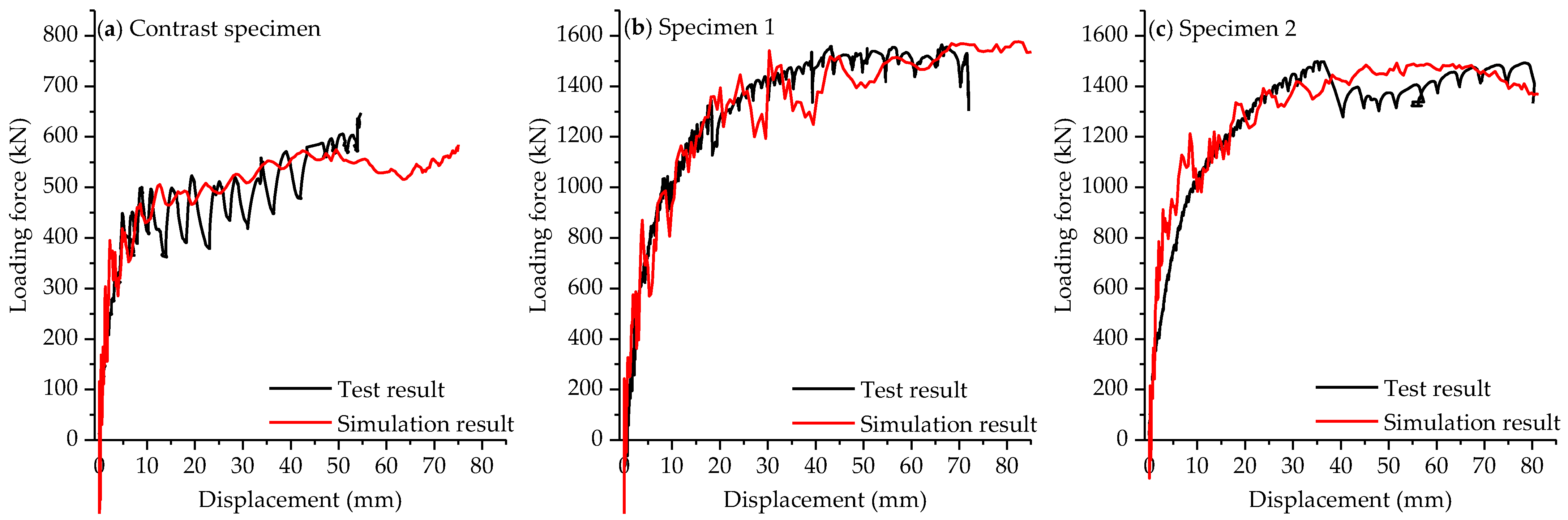
4.2. Relationship of Loading-Force–Displacement
5. Discussion
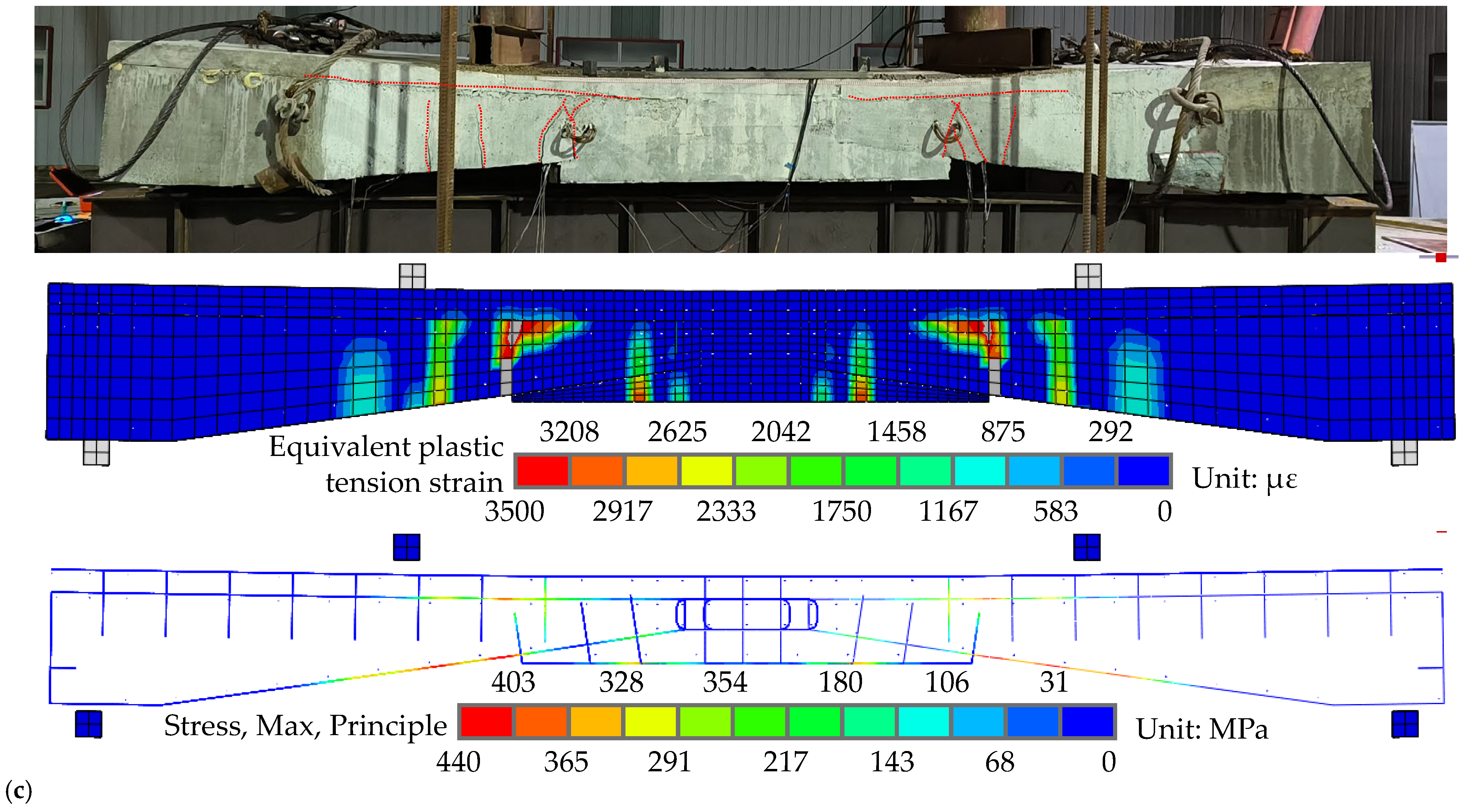
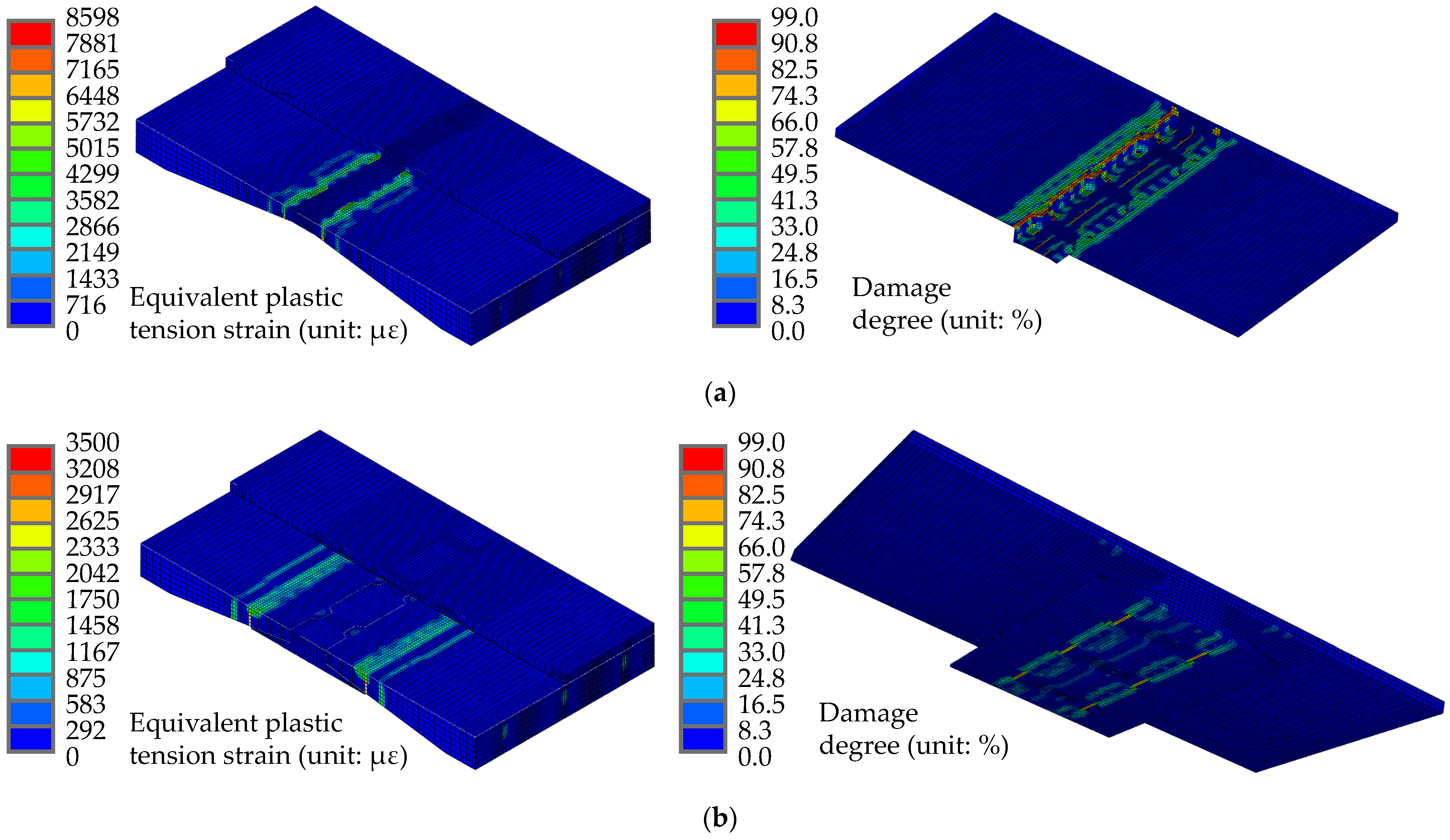
5.1. Simulation Model and Results Comparison
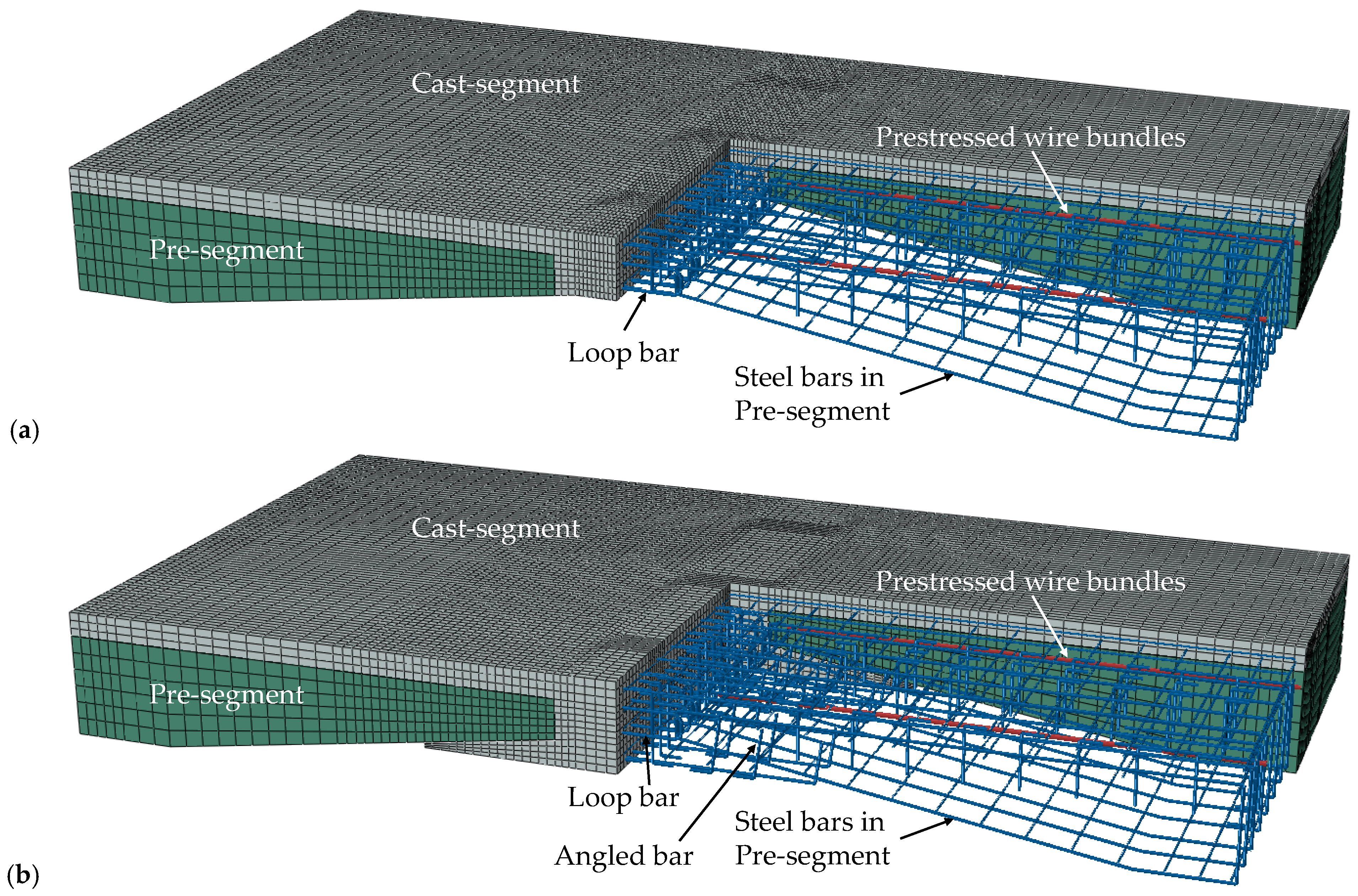
5.1.1. Simulation Model
- Material constitutive model
- 2.
- Mesh subdivision
- 3.
- Boundary conditions
- 4.
- Analysis type performed
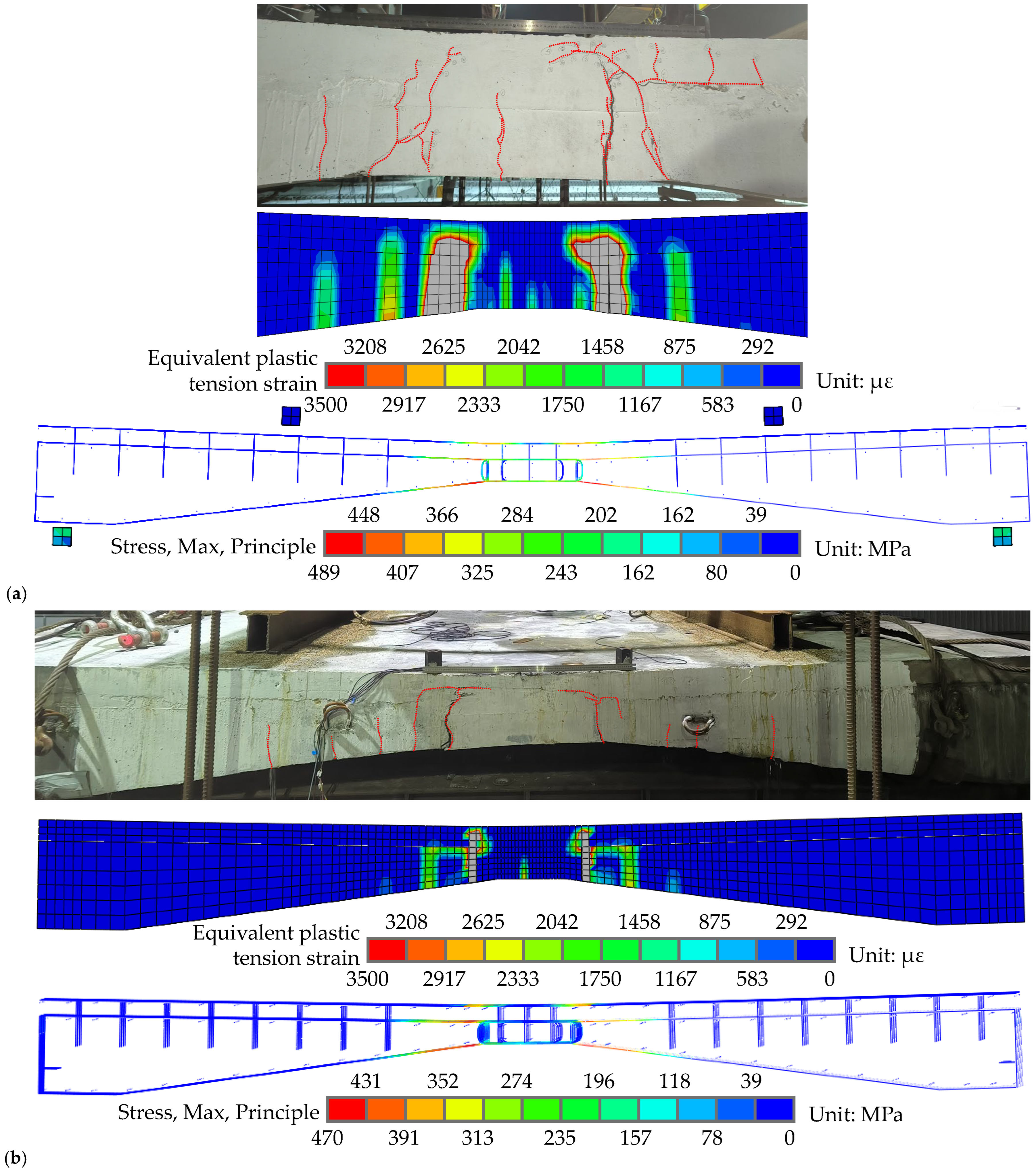
5.1.2. Comparison of Simulation Results with Test Results
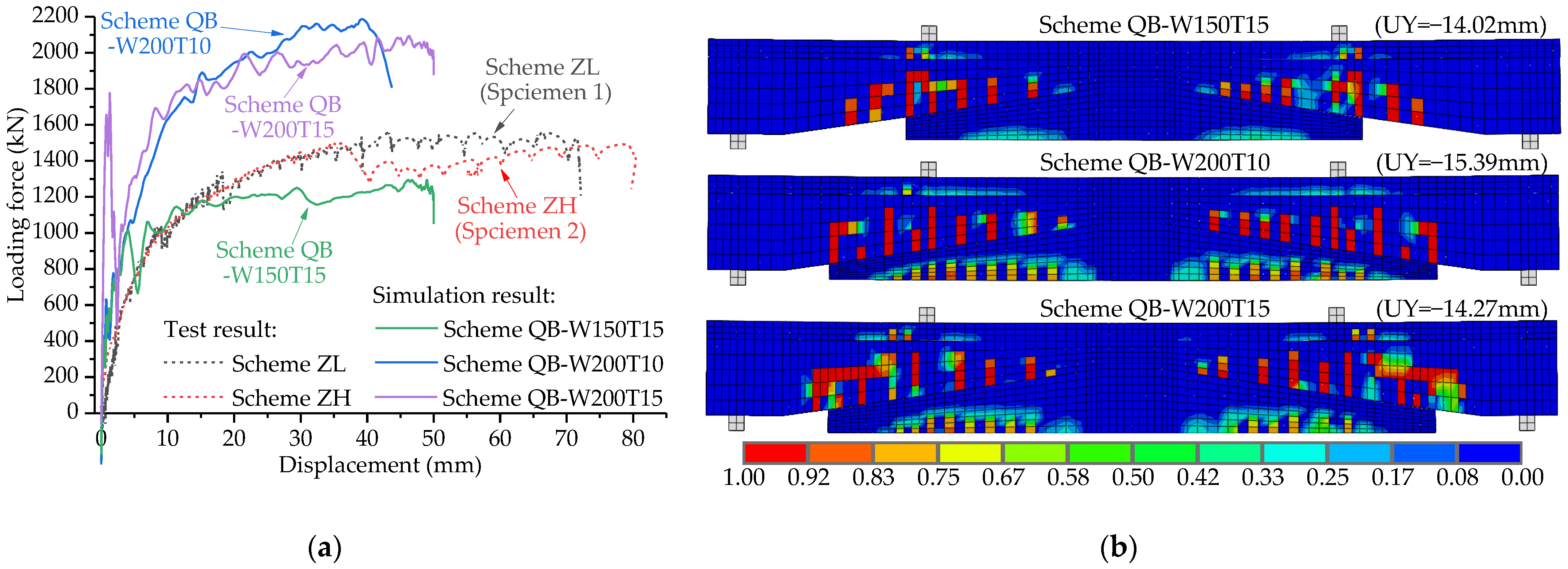
5.2. Optimization of Splicing Scheme
- Optimized for maximum composite width
- Optimized for construction convenience
6. Conclusions
- The loop bar in the joint connection segment (segment JC) should be connected to the traverse steel bar of the existing flange plate, and the application of UHPC material can ensure the effective anchorage length of the loop bar so that the integral splicing structure can effectively transfer the force to the existing flange plate.
- The failure process of the proposed integral splicing composite structure is firstly debonding at the interface and then cracking at the flange plate of the existing box girder. In order to ensure the safety of the bridge users during the normal operation of the bridge, the cracking load of the interface should be increased as much as possible. Through the calculation and test results, it is well verified that the interface cracking loads of integral splicing schemes ZL and ZH are obviously less than the load of the bridge suffered under normal condition.
- The embedded angled bar can delay the interface debonding failure and interface slip. It can make the composite segment below the flange plate (segment CF) bend together with the existing flange plate, which is beneficial to the protection of the existing flange plate.
- The refined simulation model proposed is in good agreement with the test results, and the model can be applied to optimize the splicing scheme. The size of the composite segment below the flange plate (segment CF) has a significant effect on the flexural performance of the integral splicing composite structure. Increasing its width is beneficial to delaying the interface debonding failure, and increasing its thickness can effectively delay the cracking load of the flange plate.
- When the width of segment CF is 150 cm, its end is close to the lane edge line of the designed lane layout, which puts the existing flange plate in an unfavorable state of shear stress. Segment CF with a thickness of 15 cm can increase the interface debonding load and the flange plate cracking load. Therefore, optimized splicing scheme QB-W200T15 is recommended, in which the width of segment CF is 200 cm and the minimum thickness is 15 cm.
Author Contributions
Funding
Institutional Review Board Statement
Informed Consent Statement
Data Availability Statement
Acknowledgments
Conflicts of Interest
References
- Sakib-Uz-Zaman, C.; Kabir, M.A.; Kabir, G. A Comprehensive Asset Management Plan for the Bridges of Ontario for 2023–2025. Eng. Proc. 2024, 76, 36. [Google Scholar] [CrossRef]
- Corbett, P.W.; Watterson, T.J. Widening of existing bridges on State Highway 16 in Auckland. Proc. Inst. Civ. Eng.-Bridge Eng. 2016, 169, 203–214. [Google Scholar] [CrossRef]
- Navarro-Moreno, J.; Calvo-Poyo, F.; de Oña, J. Influence of road investment and maintenance expenses on injured traffic crashes in European roads. Int. J. Sustain. Transp. 2023, 17, 649–659. [Google Scholar] [CrossRef]
- Lu, B.; Zhao, W.; Li, S.; Dong, M.; Xia, Z.; Shi, Y. Study on Seasonal Permafrost Roadbed Deformation Based on Water–Heat Coupling Characteristics. Buildings 2024, 14, 2710. [Google Scholar] [CrossRef]
- Zucca, M.; Reccia, E.; Longarini, N.; Eremeyev, V.; Crespi, P. On the structural behaviour of existing RC bridges subjected to corrosion effects: Numerical insight. Eng. Fail. Anal. 2023, 152, 107500. [Google Scholar] [CrossRef]
- Intini, P.; Blasi, G.; Fracella, F.; Francone, A.; Vergallo, R.; Perrone, D. Daniele Perrone, Predicting traffic volumes on road infrastructures in the context of multi-risk assessment frameworks. Int. J. Disaster Risk Reduct. 2024, 117, 105139. [Google Scholar] [CrossRef]
- Qin, P.; Wu, F.; Bin, S.; Li, X.; Ya, F. High-Accuracy, High-Efficiency, and Comfortable Car-Following Strategy Based on TD3 for Wide-to-Narrow Road Sections. World Electr. Veh. J. 2023, 14, 244. [Google Scholar] [CrossRef]
- McHaffie, B.; Waldin, J. Assessing the residual capacity and future performance of the Mason River Bridge, NZ. Proc. Inst. Civ. Eng.-Bridge Eng. 2019, 172, 217–225. [Google Scholar] [CrossRef]
- Li, H.; Zhang, H.; Zhao, B.; Zhao, G. Prediction methods for residual load-bearing capacity and service life of bridge cables. J. Constr. Steel Res. 2024, 219, 108797. [Google Scholar] [CrossRef]
- Tan, Z.; Yu, J.; Zhang, S. A Multi-Technique Hybrid Method for the Widening and Splicing of New and Old Beam Bridges. Sustainability 2024, 16, 6164. [Google Scholar] [CrossRef]
- Wen, Q.-J. Long-term effect analysis of prestressed concrete box-girder bridge widening. Constr. Build. Mater. 2011, 25, 1580–1586. [Google Scholar] [CrossRef]
- Nie, J.-G.; Wang, Y.-H.; Zhang, X.-G.; Fan, J.-S.; Cai, C. Mechanical behavior of composite joints for connecting existing concrete bridges and steel–concrete composite beams. J. Constr. Steel Res. 2012, 75, 11–20. [Google Scholar] [CrossRef]
- Shafighfard, T.; Kazemi, F.; Asgarkhani, N.; Yoo, D.-Y. Machine-learning methods for estimating compressive strength of high-performance alkali-activated concrete. Eng. Appl. Artif. Intell. 2024, 136, 109053. [Google Scholar] [CrossRef]
- Gu, P.; Wu, H.; Li, L.; Li, Z.; Hong, J.; Zhuang, M.-L. Effect of Traffic Vibration on Compressive Strength of High-Strength Concrete and Tensile Strength of New-to-Old Concrete Interfaces. Buildings 2024, 14, 3765. [Google Scholar] [CrossRef]
- Wang, K.; Liu, G.; Wang, C.; Wang, F. Tensile analysis of loop joints with different overlap lengths. J. Asian Archit. Build. Eng. 2024, 1–13. [Google Scholar] [CrossRef]
- Shi, X.; Zhong, Y.; Ma, H.; Hu, K.; Xie, P.; Zeng, C. Numerical analysis on tensile capacity of loop connections. Eng. Struct. 2021, 246, 113022. [Google Scholar] [CrossRef]
- Lu, K.; Xu, Q.; Li, W.; Hu, Y.; Wang, J.; Yao, Y. Fatigue performance of UHPC bridge deck system with field-cast dovetail joint. Eng. Struct. 2021, 237, 112108. [Google Scholar] [CrossRef]
- Lu, K.; Xu, Q.; Li, W.; Hu, Y.; Wang, J.; Yao, Y. Destructive testing and simulation for newly designed full-scale high-speed railway box girder. Constr. Build. Mater. 2022, 328, 127112. [Google Scholar] [CrossRef]
- Jayasooriya, D.; Rajeev, P.; Sanjayan, J. Tensile stress-strain models for steel fiber reinforced concrete. J. Build. Eng. 2024, 96, 110533. [Google Scholar] [CrossRef]
- Hu, K.; Zhu, C.; Shi, X.; Zhong, Y. Experiment on Flexural Fatigue Performance of Precast Bridge Deck Joints with Loop Connections. Appl. Sci. 2024, 14, 566. [Google Scholar] [CrossRef]
- Shen, F.; Wang, B.; Zhuge, P.; Qi, H. Flexural performance investigation of steel-concrete composite beams strengthened with prestressed CFRP tendons in the negative bending moment region. Structures 2024, 61, 106025. [Google Scholar] [CrossRef]
- Wdowiak-Postulak, A.; Gocál, J.; Bahleda, F.; Prokop, J. Load and Deformation Analysis in Experimental and Numerical Studies of Full-Size Wooden Beams Reinforced with Prestressed FRP and Steel Bars. Appl. Sci. 2023, 13, 13178. [Google Scholar] [CrossRef]
- Zhang, F.; Feng, F.; Liu, X. Reliability Analysis of Concrete Beam with High-Strength Steel Reinforcement. Materials 2022, 15, 8999. [Google Scholar] [CrossRef] [PubMed]
- JTG D60-2015; General Specification for Design of Highway Bridges and Culverts. China Communication Press: Beijing, China, 2015. (In Chinese)
- Xiang, W.; Wei, J.; Zhang, F. Structural Health Monitoring Design and Performance Evaluation of a Middle-Span Bridge. Sensors 2023, 23, 8702. [Google Scholar] [CrossRef] [PubMed]
- Hong, W.K.; Pham, T.D.; Nguyen, D.H.; Le, T.A.; Nguyen, M.C.; Nguyen, V.T. Experimental and nonlinear finite element analysis for post-tensioned precast frames with mechanical joints. J. Asian Archit. Build. Eng. 2023, 22, 2922–2945. [Google Scholar] [CrossRef]
- Razaghi, A.; Asgari Marnani, J.; Rohanimanesh, M.S. An energy-based computational scheme for the analysis of reinforced concrete structures with geometric and material nonlinearities. J. Asian Archit. Build. Eng. 2022, 22, 643–659. [Google Scholar] [CrossRef]


| Material | Specimen Number | Segment | Item | Parameter |
|---|---|---|---|---|
| Steel bar | Contrast specimen Specimens 1 and 2 | All segments | Characteristic value of tension strength | 400 MPa |
| Elastic modulus | 200 GPa | |||
| Concrete C50 | Contrast specimen Specimens 1 and 2 | Pre-segment of all specimens and Cast-segment of contrast specimen | Characteristic value of compression strength | 32.4 MPa |
| Characteristic value of tension strength | 2.65 MPa | |||
| Elastic modulus | 34.5 GPa | |||
| Passion ratio | 0.2 | |||
| UHPC | Specimens 1 and 2 | Cast-segment | Compression strength | ≥130 MPa |
| Flexural tension strength of 28 d | ≥22 MPa | |||
| Tensile strength in elastic stage | ≥7 MPa | |||
| Ultimate tensile strength | ≥9 MPa | |||
| Elastic modulus | 45 GPa | |||
| Shrinkage rate of 28 days | <200 × 10−6 |
| Specimen Number | Splicing Material | Splicing Scheme | Cracking at the Interface * | Cracking at The Flange Plate | ||
|---|---|---|---|---|---|---|
| Loading Force (kN) | Flexural Moment (kN·m) | Loading Force (kN) | Flexural Moment (kN·m) | |||
| Contrast specimen | C50 | Scheme ZL | 25 | 142.1 | 100 | 194.6 |
| Specimen 1 | UHPC | Scheme ZL | 70 | 173.6 | 500 | 474.6 |
| Specimen 2 | UHPC | Scheme ZH | 175 | 255.1 | 400 | 412.6 |
| Splicing Scheme | Size of Segment CF | Cracking at the Interface * | Cracking at the Flange Plate | |||
|---|---|---|---|---|---|---|
| Width (cm) | Thickness (cm) | Loading Force (kN) | Flexural Moment (kN·m) | Loading Force (kN) | Flexural Moment (kN·m) | |
| Scheme ZL 1 | 0 | 0 | 70 | 173.6 | 500 | 474.6 |
| Scheme ZH 1 | 2 × 80 | 5~14 | 175 | 255.1 | 400 | 412.6 |
| Scheme QB-W150T15 2 | 2 × 150 | 15~34.6 | 616 | 431.3 | 1226 | 858.2 |
| Scheme QB-W200T10 2 | 2 × 200 | 10~37.2 | 436 | 305.2 | 839 | 583.3 |
| Scheme QB-W200T15 2 | 2 × 200 | 15~42.2 | 785 | 549.5 | 1559 | 1091.3 |
Disclaimer/Publisher’s Note: The statements, opinions and data contained in all publications are solely those of the individual author(s) and contributor(s) and not of MDPI and/or the editor(s). MDPI and/or the editor(s) disclaim responsibility for any injury to people or property resulting from any ideas, methods, instructions or products referred to in the content. |
© 2025 by the authors. Licensee MDPI, Basel, Switzerland. This article is an open access article distributed under the terms and conditions of the Creative Commons Attribution (CC BY) license (https://creativecommons.org/licenses/by/4.0/).
Share and Cite
Zeng, G.; Wang, X.; Shi, X.; Zhu, C.; Song, J. Local Full-Scale Model Test on Mechanical Performance of the Integral Splicing Composite Structure of Adjacent Existing Box Girder Bridges. Buildings 2025, 15, 411. https://doi.org/10.3390/buildings15030411
Zeng G, Wang X, Shi X, Zhu C, Song J. Local Full-Scale Model Test on Mechanical Performance of the Integral Splicing Composite Structure of Adjacent Existing Box Girder Bridges. Buildings. 2025; 15(3):411. https://doi.org/10.3390/buildings15030411
Chicago/Turabian StyleZeng, Guoqiang, Xinyu Wang, Xuefei Shi, Chaoyu Zhu, and Jun Song. 2025. "Local Full-Scale Model Test on Mechanical Performance of the Integral Splicing Composite Structure of Adjacent Existing Box Girder Bridges" Buildings 15, no. 3: 411. https://doi.org/10.3390/buildings15030411
APA StyleZeng, G., Wang, X., Shi, X., Zhu, C., & Song, J. (2025). Local Full-Scale Model Test on Mechanical Performance of the Integral Splicing Composite Structure of Adjacent Existing Box Girder Bridges. Buildings, 15(3), 411. https://doi.org/10.3390/buildings15030411