1. Introduction
Squeezed branch piles (such as squeezed branch piles and rotated branch piles [
1]) are a type of pile foundation technology developed from the multi-section underreamed piles [
2] that emerged in the 1950s. Due to their excellent engineering properties [
3,
4], they have been widely used in various fields, and related research has continued uninterrupted [
5,
6,
7,
8]. A review of existing research findings reveals that current studies on squeezed branch piles mainly focus on the following aspects: bearing capacity analysis of single piles and pile groups [
9,
10], optimization of pile shape parameters [
11], and practical engineering applications [
12,
13]. Among these, research on bearing performance has always been a major focus for most scholars. However, current studies primarily concentrate on the response under vertical loads [
14,
15], while research on the mechanical behavior under horizontal loads, especially under combined loads (such as horizontal combined with uplift or horizontal combined with downward pressure), remains relatively limited.
It is worth noting that silty clay, a common type of soft soil widely distributed in coastal regions, is frequently encountered in the foundations of important infrastructure such as high-rise buildings, bridge structures, port engineering, and transmission tower bases. This type of soil is characterized by high water content, relatively high compressibility, low strength, and a tendency for creep deformation. These properties pose a series of challenges for pile foundation design in such strata, including settlement control, insufficient bearing capacity, and long-term deformation issues. Therefore, studying the mechanical behavior of squeezed branch piles in silty clay is of significant practical importance for enhancing the safety and economic efficiency of foundation engineering. Existing studies have shown that in such strata, parameters such as the disk spacing and disk diameter ratio of branch piles significantly affect their compressive and uplift bearing capacity [
16,
17].
However, systematic research on their performance under horizontal and combined loads remains relatively scarce [
18,
19]. Thus, conducting model tests under corresponding loading conditions is of great importance for further clarifying the applicability and reliability of squeezed branch piles in silty clay.
The paper carries out model tests under two types of combined loading conditions—“horizontal + uplift” and “horizontal + downward pressure”—to systematically investigate the bearing characteristics of squeezed branch piles in silty clay. The aim is to provide a scientific reference for the design of pile foundations under complex working conditions.
2. Materials and Methods
2.1. Model Materials
2.1.1. Foundation Soil Material
The foundation soil material used in this experiment was homogeneous silty clay. To ensure the particle size distribution and gradation relationship, all soil was passed through a sieve that was 0.63 mm fine. After sieving, a certain mass of soil sample was collected for indoor model testing. The geotechnical parameters of this foundation soil determined through measurements are presented in
Table 1 below.
Considering the compaction effect induced by pile installation equipment in practical engineering, the soil was compacted using custom-built tamping tools after being placed in the model container to achieve the equivalent densification effect.
2.1.2. Model Pile
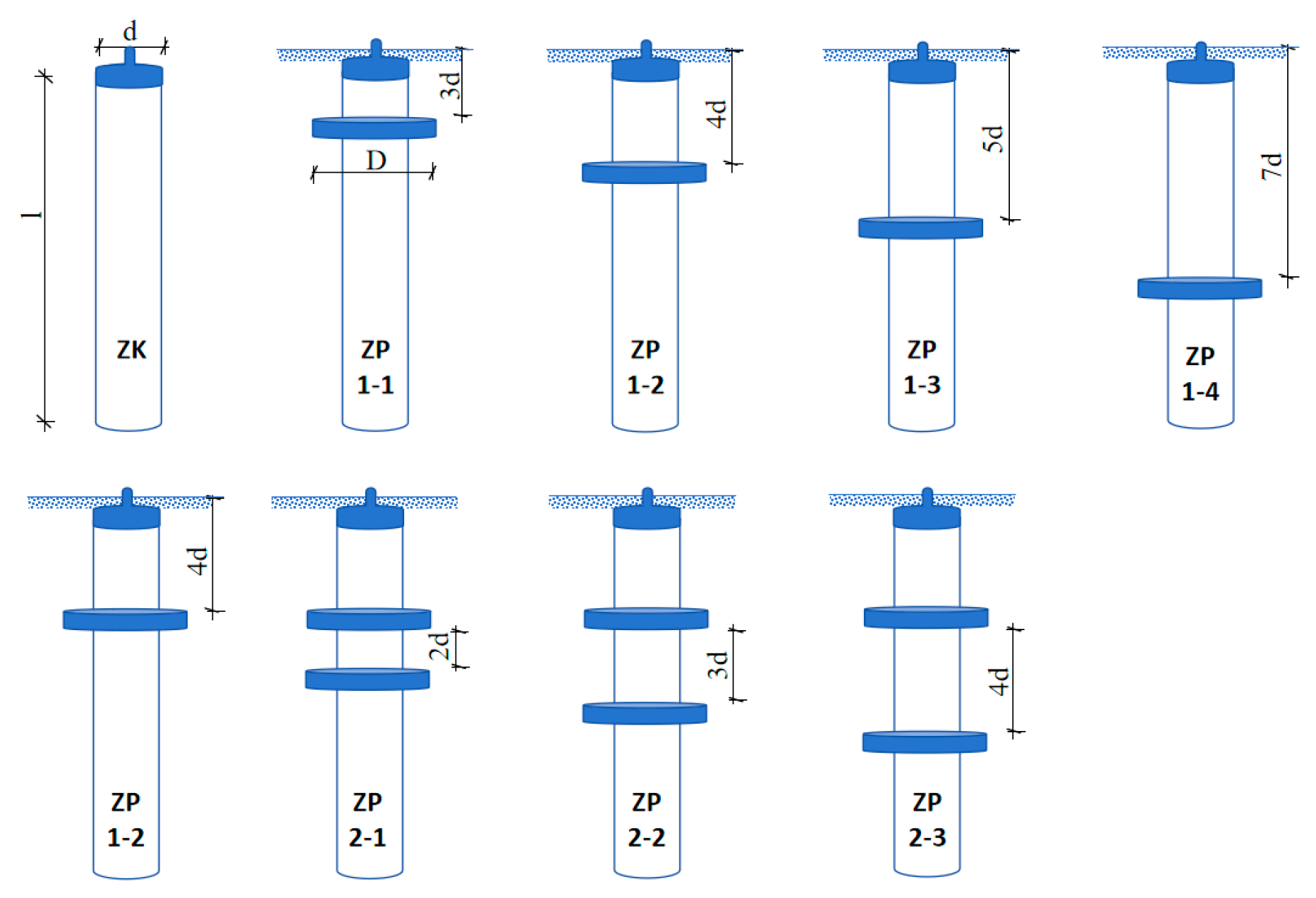
This model test program involved a total of eight pile types with different dimensions. To ensure the reliability and consistency of the test data, three identical replicate piles were manufactured for each pile type. All model piles had a designed length of 1800 mm. The bearing plates were made of the same steel material as the pile shaft. To fully mobilize the shaft friction resistance, the surface of the pile shaft was uniformly treated by grinding with fine sand. In addition, the bottom end of the pile was sealed to maintain the integrity of the pile structure. A photograph of the model piles and specific dimensions of the eight pile types are presented in
Figure 1 and
Figure 2 and
Table 2, respectively.
2.2. Test Apparatus
2.2.1. Model Test Chamber
The model test was designed based on prior research [
20,
21], employing a soil-filled test chamber measuring 2.5 m in length, 1.5 m in width, and 2 m in height. The chamber structure was manufactured from steel plates that were 10 mm thick, supplemented by welded stiffening ribs.
Figure 3 showed a schematic diagram of test chamber.
2.2.2. Loading Device
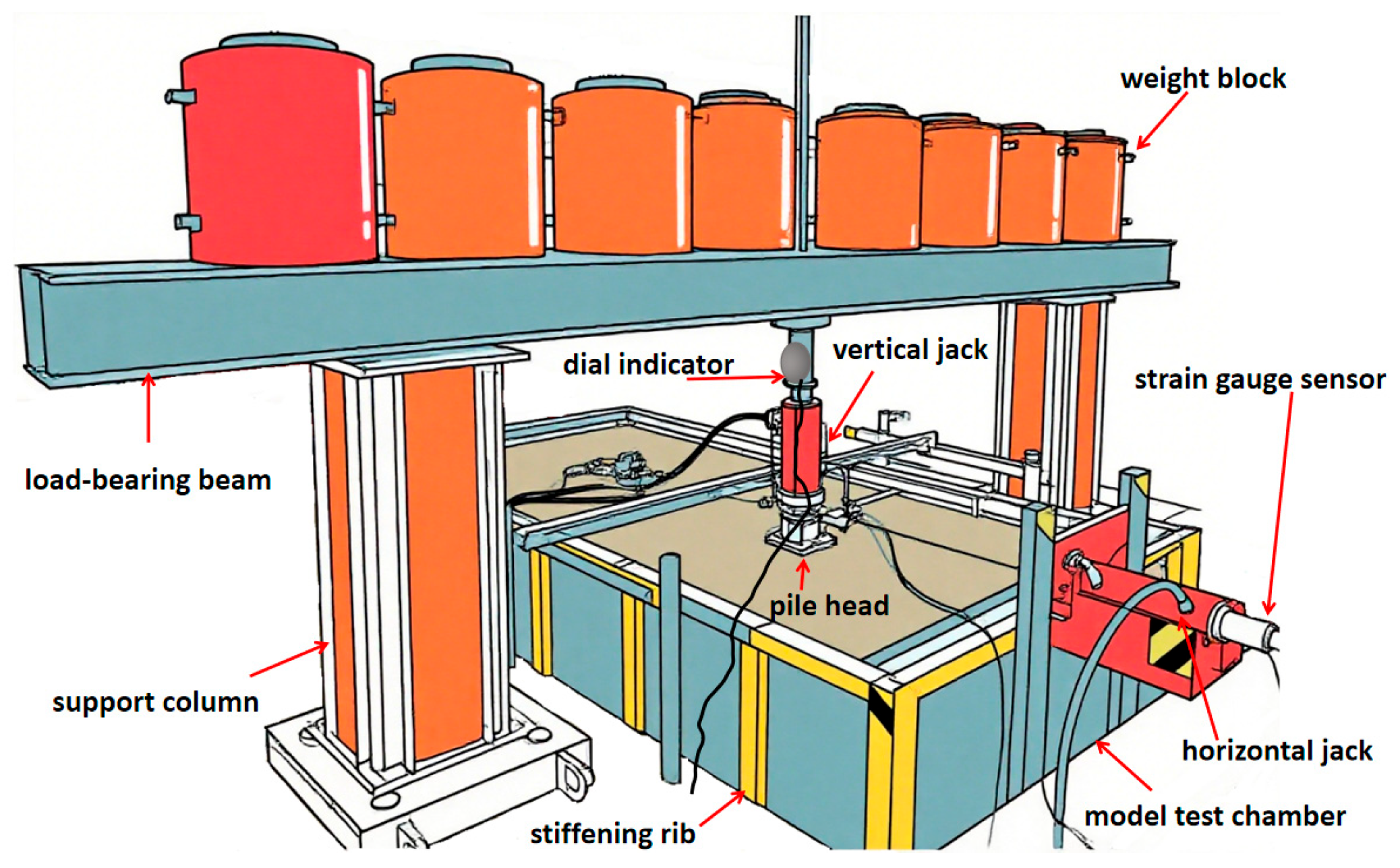
This model test utilized hydraulic jacks to apply both horizontal and vertical loads. Given the relatively small magnitude of the test loads, a jack with a capacity of 20 kN was selected, which offers a minimum loading increment of 0.01 Kn. This setup allows precise control of the loading process according to the predefined force levels, thereby facilitating accurate analysis of the variation in pile tip displacement with increasing load stages. The loading device is illustrated in
Figure 4.
2.2.3. Monitoring System
The instrumentation used in this model test primarily included strain-gauge tension sensors and dial indicators. The measurement system was divided into three parts: pile top load (vertical and horizontal), axial force at the bearing plates, and pile top displacement (vertical and horizontal). Among these, the pile top load was collected by a tension/compression sensor system connected to a strain reader; the axial force at the bearing plates was measured using tension sensors installed at the plate location; and the pile top displacement was monitored by dial indicators set up at the pile top. A physical diagram of the monitoring system is shown in
Figure 5.
Strain-gauge tension sensor: Based on the estimated maximum load in the test, a strain-gauge tension sensor with a capacity of 1 ton was selected to accurately measure the pile top load. The sensor has an input impedance of 364 Ω, an output impedance of 350 Ω, an output sensitivity of 1.508 mV/V, and a comprehensive error of ≤0.03% R.O. It complies with the Chinese National Standard GB/T 7551-2008 [
22].
Dial indicator: To accurately measure the pile tip displacement, an extended steel plate was installed at the pile tip, and dial indicators were mounted on the plate during the test. This setup ensured that the readings from the dial indicators accurately reflected the upward displacement of the pile. The configuration of the monitoring system is illustrated in
Figure 4 and
Figure 5.
2.3. Testing Methods
2.3.1. Parameter Measurement
Prior to the commencement of each test, it is necessary to understand the soil sample conditions and measure essential geotechnical data, with the most critical parameter being the water content. After determining the pre-test water content, the amount of water to be added can be calculated based on the obtained value. Water is then evenly added during the model embedding process to ensure that the water content of the soil sample remains approximately consistent across all tests. This test controls the water content at 19%.
2.3.2. Model Pile Treatment
The model pile is made of stainless steel. Its surface was overly smooth. To better simulate real-world conditions, the pile shaft surface was sanded with fine sand which was coated with it to increase its surface roughness.
2.3.3. Model Pile Embedment
For this model test, given the practical constraints of being unable to perform drilling, preformed and pre-embedded piles were used. The specific installation procedure was as follows:
Before filling the model test chamber with soil, the model pile was first secured with a wooden model fixture, positioned centrally within the test chamber, and ensured to be vertical. The horizontal distance from the center of the test chamber to the inner edge was no less than 4 D.
Soil was placed into the model chamber in thirteen layers and compacted using a manually fabricated tool. Each layer consisted of one bucket of soil, weighing approximately 25 kg. The surface of the soil was first leveled, and then uniformly compacted three times using the custom-made hammer. The drop height of the hammer remained consistent throughout the process, and the same hammer was used to ensure identical compaction energy. After compaction, any loose soil was leveled again.
The model setup was left to rest for 24 h, after which a test was conducted on the model pile.
2.3.4. Model Loading
After preparing the materials and device required for the test, the loading process was carried out in accordance with the “Technical Code for Building Pile Foundations” (JGJ 94-2008) [
23] and the “Technical Code for Testing of Building Pile Foundations” (JGJ 106-2014) [
24]. The specific loading steps were as follows:
Each stage of loading was set to be 1/10 of the estimated ultimate bearing capacity (the estimated ultimate bearing capacity was determined according to the “Design Specification for Cast-in-Place Piles with Expanded Branches and Bells by 3-way Extruding Arms” (JGJ-171-2009) [
25]. After each loading stage, measurements were taken at 5, 10, and 15 min, respectively. Subsequently, measurements were taken at 15 min intervals. After a cumulative duration of 1 h, measurements were taken at 30 min intervals. Each measured value was recorded in the test record table. The settlement was considered to have reached relative stability when the settlement did not exceed 0.1 mm within one hour and this condition occurred twice consecutively (calculated from three consecutive observation values within 1.5 h). Only after achieving relative stability was the next stage of load applied. The ratio of horizontal loading to vertical loading was 1:5 [
26]. The loading process was terminated when the horizontal displacement reached 10 mm [
27].
3. Results and Discussion
This section presents and discusses the model test results pertaining to the behavior of squeezed branch piles under various loading conditions, with particular emphasis on the influence of the number of bearing plates, their spacing, and the embedment depth of the uppermost plate on the overall bearing performance.
3.1. Bearing Mechanism of Squeezed Branch Pile
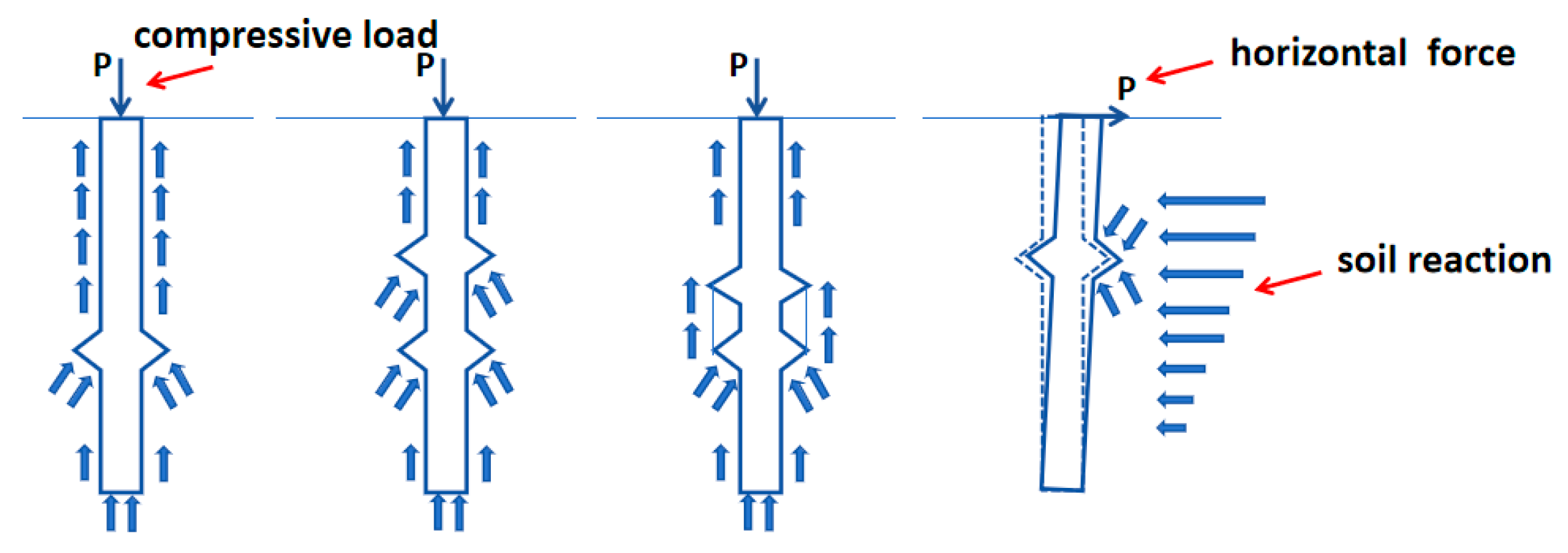
The bearing capacity situation of the squeezed branch pile can be represented by
Figure 6 and
Figure 7 below [
28].
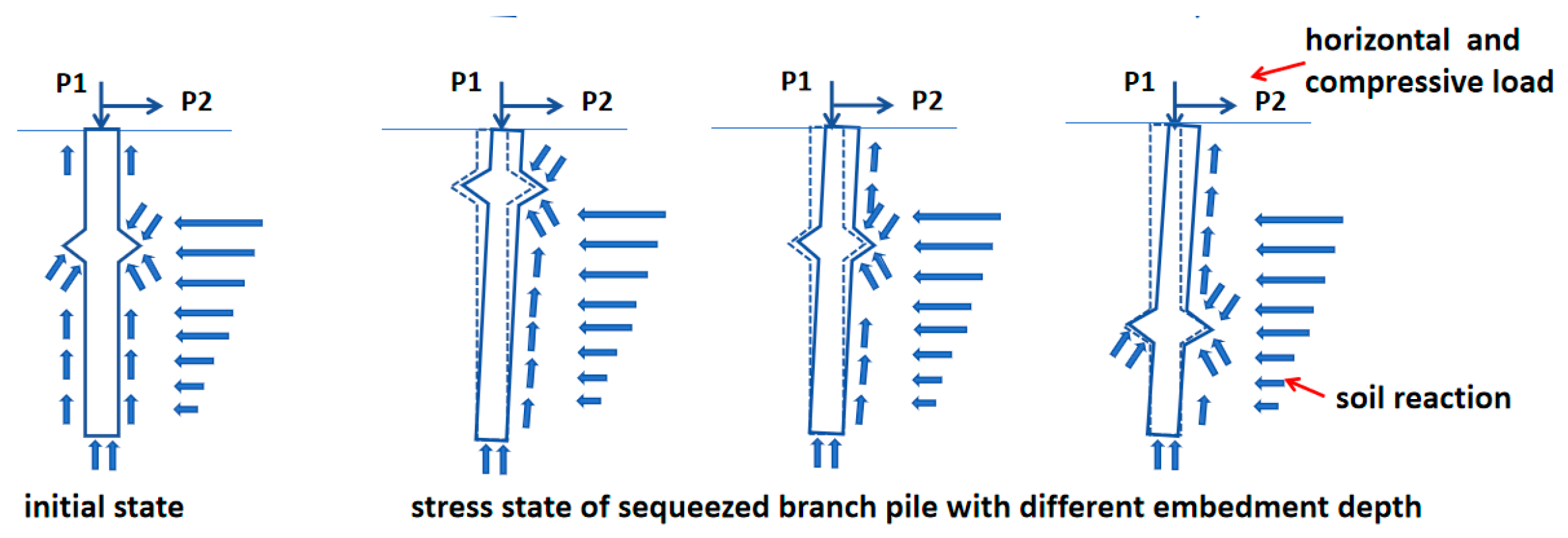
Based on the mechanical response patterns under the aforementioned single-load conditions, the squeezed branch pile may exhibit the following typical force distribution modes along the pile shaft under combined loading conditions, which were illustrated in
Figure 8 and
Figure 9 below:
The installation of plates on the squeezed branch pile increases the pile–soil contact area, allowing the plates to mobilize end-bearing capacity and thereby significantly enhance the vertical-bearing capacity. When multiple plates are installed, an adequate spacing must be maintained, as an insufficient distance between plates can reduce the bearing contribution of the inter-plate soil. Under horizontal loads, the plate structure also helps to improve the pile’s flexural and shear resistance, increasing its lateral capacity. Consequently, the bearing behavior of the pile under combined loads and the mechanism of how the plates contribute require investigation through the experimental data presented in this section.
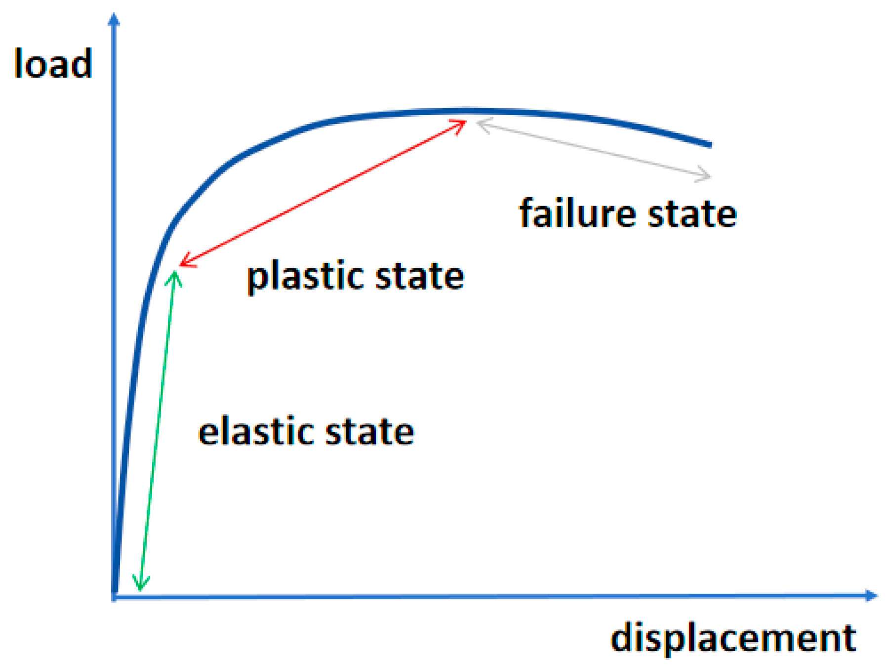
Meanwhile, considering the load-transfer mechanism, which could be found in
Figure 10, the bearing behavior of a branch pile under vertical load can be divided into three typical stages:
Stage I: The shaft resistance plays a dominant role, transferring the load to the surrounding soil.
Stage II: As the load increases, the branches gradually mobilize their end-bearing capacity, and the pile–soil system enters a plastic deformation stage.
Stage III: A further increase in load may ultimately lead to the failure of the surrounding soil or structural damage to the pile itself.
Since the branches are installed at different depths, the timing at which they engage in load-bearing varies. Therefore, investigating the influence of branch embedment depth on pile performance is of significant importance.
Under horizontal loading, the mechanical response of the branch pile can also be divided into three stages:
Stage I: The shallow soil provides the primary resistance, with minimal contribution from the branches. The relationship between pile displacement and load is approximately linear (corresponding to the initial segment of the p–y curve).
Stage II: The branches begin to exert a constraining effect on displacement, and the pile–soil system enters an elastoplastic deformation stage.
Stage III: Failure occurs due to either soil plastification or structural damage to the pile.
By integrating the bearing mechanisms under separate vertical and horizontal loads and referencing existing load–displacement curve data, the behavior of squeezed branch piles under combined loading conditions can be inferred.
3.2. Analysis of Bearing Capacity Under Horizontal + Uplift Loading
In order to investigate the bearing behavior of squeezed branch piles under horizontal and uplift loads, this section presents and discusses the load–displacement data from model tests, along with an analysis of the axial forces at the branches.
3.2.1. Load–Displacement Behavior of Piles Under Horizontal + Uplift Loading
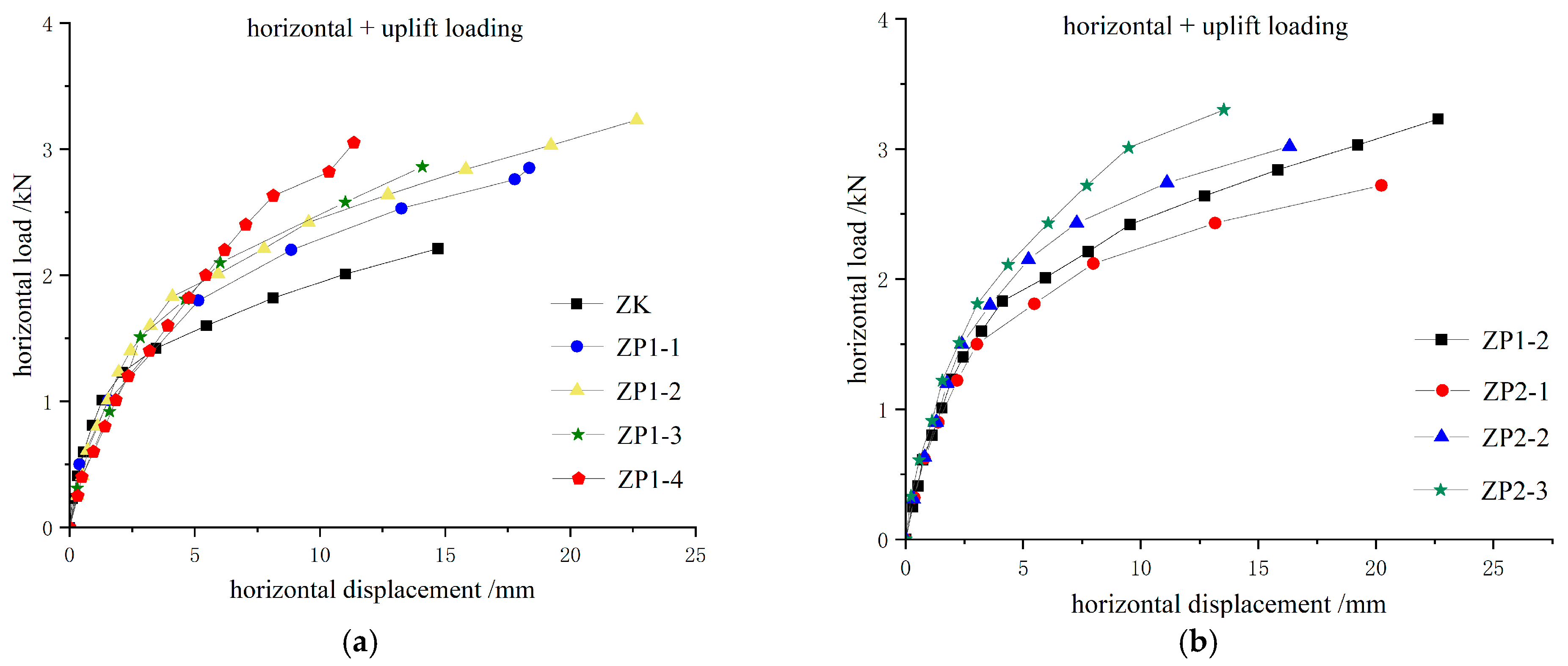
Figure 11 illustrates the relationship between horizontal load and displacement, while
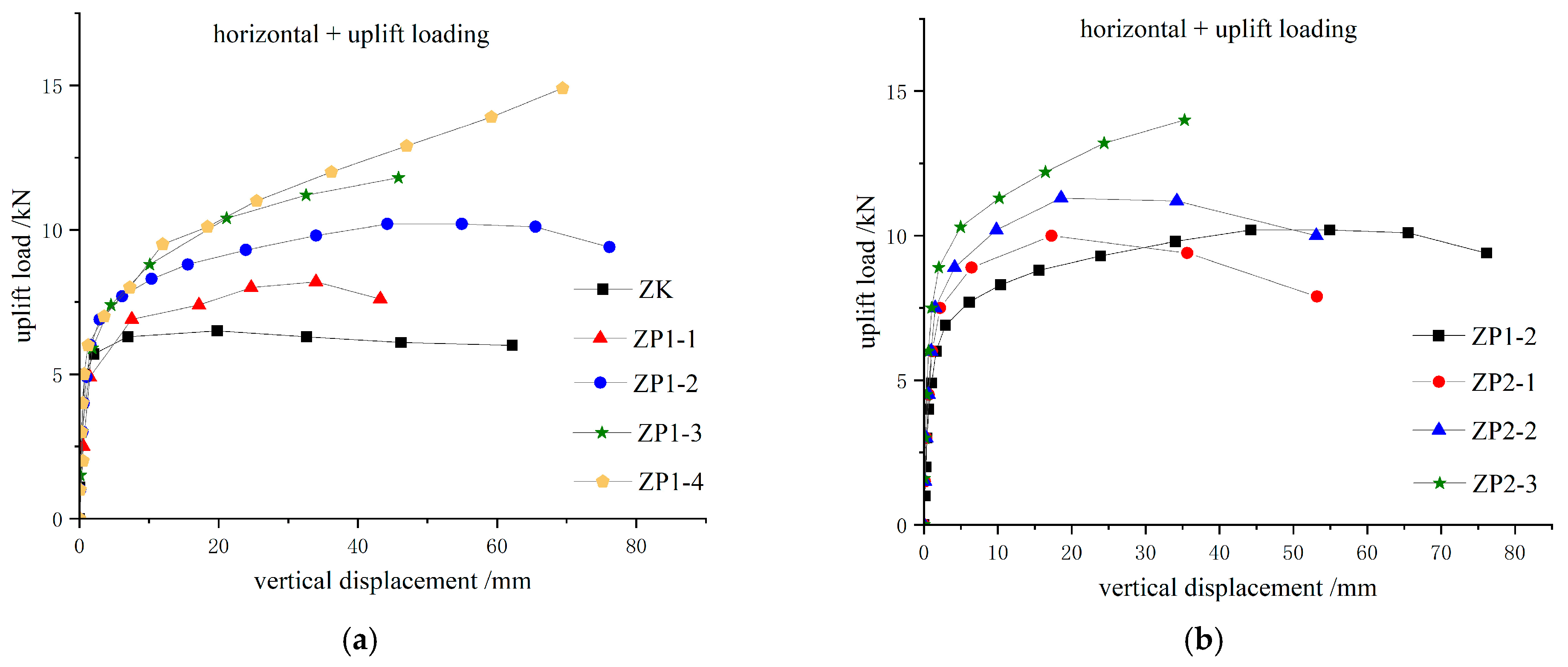
Figure 12 presents the vertical load–displacement curve.
As shown in
Figure 11 and
Figure 12, under combined horizontal and uplift loading, the load–displacement curves of the squeezed branch piles follow trends consistent with those observed under single-load conditions. This consistency is particularly evident in the vertical load–displacement curve. Given the horizontal-to-uplift load ratio of 1:5, the three characteristic-bearing stages are more distinctly exhibited in the vertical displacement response under combined loading.
Subplot (a) in both
Figure 11 and
Figure 12 indicates that both the horizontal and uplift capacities of the branch piles exceed those of the straight-shaft piles. For single-plate piles, the bearing capacity increases with greater embedment depth of the plate. Subplot (b) in both
Figure 11 and
Figure 12 further demonstrates that double-plate piles generally outperform single-plate piles in capacity. However, specimen ZP2-1 exhibited lower horizontal and uplift capacities than the single-plate pile ZP1-2, indicating that an excessively small plate spacing diminishes the load-bearing contribution of the plates.
A comparison based on the load values at a horizontal displacement of 10 mm reveals the following: in terms of horizontal capacity, single-plate piles show a 17–43% increase compared to straight-shaft piles, which escalates with deeper embedment; double-plate piles achieve a 7–24% improvement over single-plate piles, which rises with larger plate spacing (see
Table 3). A similar trend is observed for uplift capacity, with single-plate piles exhibiting a 22–122% gain and double-plate piles exhibiting a 13–34% enhancement.
3.2.2. The Elastic Recovery of Axial Force of Plates Under Horizontal + Uplift Loading
Analysis of the axial forces in the branches under combined horizontal uplift loading reveals the variation patterns in the upper and lower plates, reflecting their differences in the load-transfer mechanism.
As indicated in
Table 4, the total elastic recovery of axial force in double-plate piles is consistently greater than that in single-plate piles. This demonstrates that under combined loading conditions, the bearing plates in double-plate bear significantly higher axial forces, further confirming their superior uplift resistance capacity compared to single-plate configurations. With the increasing embedment depth, the axial force on the plate peaks at a depth of 4 d. Furthermore, as the spacing between plates widens, the total axial force borne by the plates demonstrates a gradual upward trend. Based on comparative analysis of axial forces between the upper- and lower-bearing plates, the upper plate consistently bears greater axial forces than its lower counterpart. This demonstrates that under combined loading conditions, the upper plate sustains higher mechanical performance in resisting structural deformation.
3.3. Analysis of Bearing Capacity Under Horizontal + Compressive Loading
In order to investigate the bearing behavior of squeezed branch piles under horizontal and compressive loads, this section presents and discusses the load–displacement data from model tests, along with an analysis of the axial forces at the branches.
3.3.1. Load–Displacement Behavior of Piles Under Horizontal + Compressive Loading
Figure 13 illustrates the relationship between horizontal load and displacement, while
Figure 14 presents the vertical load–displacement curve.
As shown in
Figure 13 and
Figure 14, under combined horizontal and compressive loading, the overall load–displacement curves of the squeezed branch pile are similar in shape to those under single-loading conditions. The squeezed branch pile demonstrates superior performance to the straight-shaft pile in terms of both horizontal-bearing capacity and compressive capacity.
As observed in
Figure 13a and
Figure 14a, it can be observed that the bearing capacity of the squeezed branch and plate pile increases progressively with the embedment depth of the bearing plates.
Figure 13b and
Figure 14b indicate that the overall bearing capacity of double-plate piles is generally higher than that of single-plate piles. The only exception is test pile ZP2-1, whose bearing capacity is even lower than that of the single-plate pile. This is primarily attributed to the excessively small plate spacing, which prevents the soil between the plates from fully mobilizing its bearing capacity. The corresponding load-transfer mechanism can be referred to in
Figure 6 and
Figure 7. Furthermore, as the plate spacing increases, the bearing capacity of the pile also shows an increasing trend.
A comparison based on the load values at a horizontal displacement of 10 mm reveals the following: in terms of horizontal capacity, single-plate piles showed a 12–45% increase compared to straight-shaft piles, which escalates with deeper embedment; double-plate piles achieved a 2–3% improvement over single-plate piles, which rises with larger plate spacing (see
Table 5). A similar trend is observed for compressive capacity, with single-plate piles exhibiting a 14–47% gain and double-plate piles exhibiting a 3–4% enhancement.
3.3.2. The Elastic Recovery of Axial Force of Plates Under Horizontal + Compressive Loading
Analysis of the axial forces in the branches under combined horizontal compressive loading reveals the variation patterns in the upper and lower plates, reflecting their differences in the load-transfer mechanism.
Based on the data presented in
Table 6, the cumulative axial force rebound of double-plate piles consistently exceeds that of single-plate piles. This indicates that the bearing plates significantly contribute to resisting axial forces under horizontal and vertical loads, reaffirming the superior vertical-bearing capacity of double-plate piles compared to single-plate piles. As the embedment depth increases, the cumulative axial force rebound of the bearing plates peaks at a depth of 4 d. Furthermore, comparison of axial forces between the upper and lower plates reveals that the upper plate typically bears greater axial forces than the lower plate. This demonstrates that under such combined loading conditions, the upper plate exhibits superior deformation resistance relative to the lower plate.
3.4. Comparison with Similar Results
To contextualize the findings within a broader academic framework, this study conducts a comparative analysis with selected literature representative of pile types and research methodologies. Due to differences in specific soil conditions and geometric parameters, a direct comparison of absolute bearing capacity values is of limited significance. Therefore, the comparison in this section focuses primarily on the consistency in the underlying mechanisms revealed by the overall shape and evolutionary trends of the load–displacement curves, thereby verifying the reliability of the model used in this study and highlighting its distinctive features.
3.4.1. General Consistency in Curve Behavior
The load–displacement curve obtained in this study exhibits a typically gradual pattern without a pronounced steep drop. This trend aligns with the model test results of squeezed branch piles in silty soil under horizontal uplift, as reported in the literature [
29]. Although the soil type in the cited study was silt, differing from the silty clay in this paper, both cases consistently demonstrate that the horizontal displacement is less than the vertical uplift displacement.
3.4.2. The Load-Bearing Behavior of the Branches
A pertinent comparison can be drawn with the findings reported in “Bearing Behavior of Squeezed Branch Pile Groups under Combined Loading [
30].” Both studies investigate the load-bearing performance of squeezed branch piles under combined horizontal and compressive loading, utilizing similar soil types. The main differences lie in the fact that the aforementioned study applied a slightly different ratio of horizontal to compressive load and incorporated a pile cap in its analysis. Despite these variations, it consistently confirmed the same load-bearing characteristics observed in our research: the bearing capacity of branch piles increases with the size of the bearing plates and also shows an increasing trend with greater pile spacing. Furthermore, its recommended optimum pile spacing of 4 d aligns with the conclusion presented in this paper.
Building upon the model test results and the fundamental behavioral patterns of squeezed branch piles under combined loading established in this study, future work could be extended to other soil types to validate the general applicability of these findings. Furthermore, numerical simulation is recommended to gain deeper insight into the failure mechanisms.
4. Conclusions
Based on a systematic comparison of the mechanical responses of straight-shaft piles and single-plate piles under horizontal uplift and horizontal compressive loading, this study reveals the load-dependent behavior of branched piles and proposes optimized design principles. The key conclusions are as follows:
Under horizontal combined loads, including both uplift and compression, squeezed branch piles demonstrate superior performance over straight-shaft piles by effectively mobilizing soil-arching effects via the bearing plates. Specifically, under horizontal uplift loading, the horizontal and uplift capacities are enhanced by 17–56% and 22–115%, respectively. Under horizontal compressive loading, the corresponding improvements are 12–47% in horizontal capacity and 14–49% in compressive capacity.
Owing to the composite confinement effect, double-plate piles show increase in overall deformation resistance under combined loads compared to single-plate piles. It should be noted, however, that at a plate spacing of 2 d, an adverse superposition effect occurs, leading to a marginally lower capacity than that of a single-plate pile.
The bearing capacity of the plates in squeezed branch piles under combined loading conditions is critically influenced by the embedment depth of the first plate. Measurements of the axial force rebound show a significant peak at a depth of 4 d (where d is the pile shaft diameter). These results indicate that a depth of 4 d may represent an optimal embedment depth for maximizing the pile’s load-bearing efficiency under such complex stress states.
The upper plate consistently bears 16–105% higher axial forces than the lower plate, confirming its core role in resisting deformation. This significant disparity unequivocally confirms the upper plate’s role as the primary load-bearing component in resisting deformation under combined loads. The dominance of the upper plate can be attributed to its position, which allows it to intercept and mobilize a greater share of the shear resistance from the surrounding soil before the load is transferred to the deeper lower plate. This mechanism highlights the critical influence of the upper plate on the overall performance of the pile system.
Author Contributions
Conceptualization, T.D., K.P., and Z.H.; methodology, T.D., K.P., and Z.H.; software, T.D., K.P., H.L., and Z.H.; validation, T.D., K.P., and Z.H.; formal analysis, T.D., K.P., H.L., and Z.H.; investigation, T.D., K.P., H.L., and Z.H.; resources, T.D., K.P., and Z.H.; data curation, T.D., K.P., and H.L.; writing—original draft preparation, T.D., K.P., H.L., and Z.H.; visualization, T.D., K.P., H.L., and Z.H. All authors have read and agreed to the published version of the manuscript.
Funding
This research received no external funding.
Data Availability Statement
The original contributions presented in this study are included in the article. Further inquiries can be directed to the corresponding author.
Conflicts of Interest
Author Kun Peng was employed by the company Power China Jiangxi Electric Power Engineering Co., Ltd. The remaining authors declare that the research was conducted in the absence of any commercial or financial relationships that could be construed as a potential conflict of interest.
References
- Gao, X.J.; Zhu, X.R. Theory Research and Engineering Application of Branched Piles; Science Press: Beijing, China, 2010. [Google Scholar]
- Xu, Z.J. Design, Construction and Engineering Application of Compaction Piles; China Standards Press: Beijing, China, 2011; pp. 1–466. ISBN 978-7-5066-6087-7. [Google Scholar]
- Wang, D.H.; Ju, Y.Z.; Song, M.; Zhao, J.; Bai, J. Uplift Bearing Capacity of Squeezed Branch Pile Group. Geotech. Geol. Eng. 2022, 41, 283–293. [Google Scholar] [CrossRef]
- Qian, Y.M.; Liu, J.L.; Wang, R.Z.; Jin, Y.J. Experimental study on influence of disc position on soil failure state of expanded pile under horizontal force in oceanographic engineering. J. Coast. Res. 2020, 108, 274–282. [Google Scholar] [CrossRef]
- Yang, Y.Q.; Ma, H.W.; Hu, Z.T.; Wang, L.; Chen, X. The Calculation Method for the Horizontal Bearing Capacity of Squeezed Branch Piles Considering the Plate–Soil Nonlinear Interaction. Appl. Sci. 2023, 13, 13229. [Google Scholar] [CrossRef]
- Zhang, K.B.; Wang, Y.M.; Chen, Y.K.; Qiu, S.; Yi, H.; Yang, J. Investigation of the Axial-Bearing Mechanism of Single and Group Squeezed Branch Piles in Soft Soil Combining Field Measurements and Numerical Modeling. Int. J. Geomech. 2025, 25, 04025225. [Google Scholar] [CrossRef]
- Ma, H.W.; Zhang, W.Q.; Ma, G.Q. Prediction method for uplift capacity of squeezed branch pile based on load transfer method. Ocean Eng. 2025, 334, 121603. [Google Scholar] [CrossRef]
- Zhang, S.Q.; Liu, X.F.; Zhang, H.J.; Piao, C.; Niu, Y. Study on the Force Model of Squeezed Branch Piles Based on Surface Potential Characteristics. Buildings 2023, 13, 2231. [Google Scholar] [CrossRef]
- Li, T.; Xu, P.; Yang, G.Q. Investigation into bearing performance of concrete expanded-plates piles: Field test and numerical modeling. Eng. Struct. 2022, 10, 114954. [Google Scholar] [CrossRef]
- Qian, Y.M.; Cao, Q.Z.; Yang, Y.; Teng, D.; Zhou, T.T. Influence of pile spacing on the compressive bearing performance of CEP groups. Buildings 2024, 14, 1447. [Google Scholar] [CrossRef]
- Qian, Y.M.; Chen, X.; Sun, L.; Wang, X.H.; Chen, Y. Effects of staggered plates on the uplift failure state and bearing capacity of NT-CEP pile groups. Buildings 2024, 14, 719. [Google Scholar] [CrossRef]
- Li, Z.; Meng, Y.; Zheng, R.; Hou, B.; Wu, Z.Y. Application of squeezed branch piles in an engineering project. Build. Struct. 2023, 52, 2465–2469. [Google Scholar]
- Yang, P.W.; Tang, M. Application of squeezed branch piles in Shiziyang Passage bridge project. Highway 2024, 69, 147–151. [Google Scholar]
- Yi, H.; Zhang, K.B.; Chen, Y.K.; Wang, Y.M. Research on Vertical Bearing Characteristics of Squeezed Branch Piles in Soft Soil Areas. World Bridges 2021, 49, 79–86. [Google Scholar]
- Xie, H.L.; Wang, M.M.; Tian, Y.Q.; Ren, Y.; Zhou, Z. Numerical Analysis of Bearing Characteristics and Settlement Behavior of Squeezed Branch Piles. J. Archit. Civ. Eng. 2025, 42, 197–206. [Google Scholar]
- Gao, X.J.; Qi, C.W. Determination of Optimal Nodule Location and Spacing for Rotary Expanded Nodular Piles. J. Geotech. Investig. Surv. 2009, 37, 13–17. [Google Scholar]
- Wang, Y.M.; Zhang, K.B.; Qiu, S.; Chen, Y.; Xv, D.; Yang, J. A Comparative Study of Design Parameters and Bearing Characteristics of Squeezed Branch Piles Based on Current Codes. Build. Struct. 2023, 53, 2648–2653. [Google Scholar]
- Kong, L.G.; Jiang, L.H.; Chen, R.P.; Fan, J.; Lin, G.; Chen, Y. Response Analysis of Squeezed Branch Piles under Inclined Uplift Load. Chin. J. Appl. Mech. 2013, 30, 228–233. [Google Scholar]
- Wang, D.H.; Shi, R.J.; Zhao, X.P.; Ju, Y.; Bai, J. Mechanical Performance and Economic Analysis of Pile Groups with Squeezed Branches for UHV Transmission Lines. J. Northeast Electr. Power Univ. 2020, 40, 65–70. [Google Scholar]
- Li, T.B.; Lu, C.Y.; Wang, K.Y. Model test study on working behavior of branched piles. J. Zhejiang Univ. Technol. 2008, 36, 290–294. [Google Scholar]
- Lu, C.Y.; Shou, Y.F.; Ju, R.X.; Wang, D. Study on influence of different shaped plate combination on bearing behavior of branched piles. J. Zhejiang Univ. Technol. 2015, 45, 467–472. [Google Scholar]
- GB/T 7551-2008; Load Cells. Standardization Administration of China: Beijing, China, 2008.
- JGJ 94-2008; Technical Code for Building Pile Foundations. Ministry of Housing and Urban-Rural Development of the People’s Republic of China: Beijing, China, 2008.
- JGJ 106-2014; Technical Code for Testing of Building Foundation Piles. Ministry of Housing and Urban-Rural Development of the People’s Republic of China: Beijing, China, 2014.
- JGJ 171-2009; Design Specification for Cast-in-Place Piles with Expanded Branches and Bells by 3-Way Extruding Arms. Ministry of Housing and Urban-Rural Development of the People’s Republic of China: Beijing, China, 2009.
- DL/T 5219-2005; Technical Regulation for Designing Foundation of Overhead Transmission Line. National Energy Administration: Beijing, China, 2005.
- Huang, Z.X.; Qian, Y.M.; Zhai, L. Influence of Vertical Load on the Lateral Behavior of Concrete Enlarged-Base Piles. Low Temp. Archit. Technol. 2017, 39, 59–62. [Google Scholar]
- Liu, J.; Guo, K.; Jiang, X.F. A Method for Calculation of the Bearing Capacity of Cast-In-Situ Piles with Expanded Branches and Plates. Build. Sci. 2007, 23, 32–36. [Google Scholar]
- Han, W.F.; Feng, B.B.; Zhou, J.; Lu, C.Y. The study on the engineering properties of squeezed branch piles under combined load. Adv. Civ. Ind. Eng. IV 2014, 580–583, 371–375. [Google Scholar] [CrossRef]
- Ju, Y.Z.; Song, M.Z.; Wang, D.H.; Bai, J.; Zhao, X. Bearing Behavior of Squeezed Branch Pile Groups under Combined Loading. J. Basic Sci. Eng. 2019, 27, 918–930. [Google Scholar]
Figure 1.
Photograph of model piles.
Figure 1.
Photograph of model piles.
Figure 2.
Schematic diagram of model piles.
Figure 2.
Schematic diagram of model piles.
Figure 3.
Schematic diagram of test chamber.
Figure 3.
Schematic diagram of test chamber.
Figure 4.
Schematic diagram of loading device.
Figure 4.
Schematic diagram of loading device.
Figure 5.
Photograph of monitoring system. (a) Front view; (b) close-up view.
Figure 5.
Photograph of monitoring system. (a) Front view; (b) close-up view.
Figure 6.
Schematic of the pile when subjected to uplift load and horizontal load separately.
Figure 6.
Schematic of the pile when subjected to uplift load and horizontal load separately.
Figure 7.
Schematic of the pile when subjected to compressive load and horizontal load separately.
Figure 7.
Schematic of the pile when subjected to compressive load and horizontal load separately.
Figure 8.
Schematic of the pile subjected to combined horizontal and uplift loads.
Figure 8.
Schematic of the pile subjected to combined horizontal and uplift loads.
Figure 9.
Schematic of the pile subjected to combined horizontal and compressive loads.
Figure 9.
Schematic of the pile subjected to combined horizontal and compressive loads.
Figure 10.
Diagram of load–displacement curve.
Figure 10.
Diagram of load–displacement curve.
Figure 11.
Horizontal load–displacement curve under horizontal + uplift loading. (a) Load–displacement curves of straight-shaft pile and single-plate piles; (b) load–displacement curves of double-plate piles with different spacing.
Figure 11.
Horizontal load–displacement curve under horizontal + uplift loading. (a) Load–displacement curves of straight-shaft pile and single-plate piles; (b) load–displacement curves of double-plate piles with different spacing.
Figure 12.
Uplift load–displacement curve under horizontal + uplift loading. (a) Load–displacement curves of straight-shaft pile and single-plate piles; (b) load–displacement curves of double-plate piles with different spacing.
Figure 12.
Uplift load–displacement curve under horizontal + uplift loading. (a) Load–displacement curves of straight-shaft pile and single-plate piles; (b) load–displacement curves of double-plate piles with different spacing.
Figure 13.
Horizontal load–displacement curve under horizontal + compressive loading. (a) Load–displacement curves of straight-shaft pile and single-plate piles; (b) load–displacement curves of double-plate piles with different spacing.
Figure 13.
Horizontal load–displacement curve under horizontal + compressive loading. (a) Load–displacement curves of straight-shaft pile and single-plate piles; (b) load–displacement curves of double-plate piles with different spacing.
Figure 14.
Compressive load–displacement curve under horizontal + compressive loading. (a) Load–displacement curves of straight-shaft pile and single-plate piles; (b) load–displacement curves of double-plate piles with different spacing.
Figure 14.
Compressive load–displacement curve under horizontal + compressive loading. (a) Load–displacement curves of straight-shaft pile and single-plate piles; (b) load–displacement curves of double-plate piles with different spacing.
Table 1.
Geotechnical parameters of silty clay.
Table 1.
Geotechnical parameters of silty clay.
| Foundation Soil | Density
(g·cm−3) | Specific Gravity of Soil Particles | Moisture Content
(%) | Cohesion
(kPa) | Internal Friction Angle ψ(°) | Elastic Modulus
(MPa) |
|---|
| Silty clay | 2.12 | 2.72 | 14 | 19 | 29 | 30 |
Table 2.
Dimensional details of model piles.
Table 2.
Dimensional details of model piles.
| Number of Bearing Plates | Configuration | Pile
Identifier | Embedment Depth of the 1st Bearing Plate
(mm) | Spacing Between 1st and 2nd Bearing Plates
(mm) | Note |
|---|
| 0 | 1 | ZK | / | / | d (pile shaft diameter), d = 200 mm;
D (bearing plate diameter), D = 400 mm;
l (pile length), l = 1800 mm. |
| 1 | 2 | ZP1-1 | 3d (600 mm) | / |
| 3 | ZP1-2 | 4d (800 mm) | / |
| 4 | ZP1-3 | 5d (1000 mm) | / |
| 5 | ZP1-4 | 7d (1400 mm) | / |
| 2 | 6 | ZP2-1 | 4d (800 mm) | 2d (400 mm) |
| 7 | ZP2-2 | 4d (800 mm) | 3d (600 mm) |
| 8 | ZP2-3 | 4d (800 mm) | 4d (800 mm) |
Table 3.
Comparison of bearing capacity under horizontal + uplift loading.
Table 3.
Comparison of bearing capacity under horizontal + uplift loading.
| Pile Identifier | Horizontal
Displacement
(mm) | Lateral Capacity
(N) | Increase Compared to Straight-Shaft Pile (%) | Increase Compared to Single-Plate Pile (%) | Uplift
Capacity
(N) | Increase Compared to Straight-Shaft Pile (%) | Increase Compared to Single-Plate Pile (%) |
|---|
| ZK | 10 | 194.29 | / | / | 617.06 | / | / |
| ZP1-1 | 10 | 228.62 | 17.67 | / | 755.66 | 22.46 | / |
| ZP1-2 | 10 | 245.16 | 26.18 | / | 985.75 | 59.75 | / |
| ZP1-3 | 10 | 256.26 | 31.90 | / | 1007.62 | 63.29 | / |
| ZP1-4 | 10 | 278.89 | 43.54 | / | 1373.60 | 122.60 | / |
| ZP2-1 | 10 | 224.04 | 15.31 | −8.61 | 976.70 | 56.82 | −0.92 |
| ZP2-2 | 10 | 263.58 | 35.66 | 7.51 | 1122.90 | 81.98 | 13.91 |
| ZP2-3 | 10 | 304.69 | 56.82 | 24.28 | 1330.19 | 115.57 | 34.94 |
Table 4.
The rebound of the axial force of branch piles under the horizontal + uplift loading.
Table 4.
The rebound of the axial force of branch piles under the horizontal + uplift loading.
| Pile Identifier | Embedment Depth of the 1st Bearing Plate
(mm) | Spacing Between 1st and 2nd Bearing Plates
(mm) | The Rebound of the Axial Force
(kN) |
|---|
| ZP1-1 | 600 | | 4.14 |
| ZP1-2 | 800 | | 11.166 |
| ZP1-3 | 1000 | | 9.987 |
| ZP1-4 | 1400 | | 6.921 |
| ZP2-1 (up) | | | 7.413 |
| ZP2-1 (down) | 800 | 400 | 3.992 |
| ZP2-2 (up) | | | 8.679 |
| ZP2-2 (down) | 800 | 600 | 4.946 |
| ZP2-3 (up) | | | 10.916 |
| ZP2-3 (down) | 800 | 800 | 5.337 |
Table 5.
Comparison of bearing capacity under horizontal + compressive loading.
Table 5.
Comparison of bearing capacity under horizontal + compressive loading.
| Pile Identifier | Horizontal
Displacement
(mm) | Lateral Capacity
(N) | Increase Compared to Straight-Shaft Pile (%) | Increase Compared to Single-Plate Pile (%) | Compressive
Capacity
(N) | Increase Compared to Straight-Shaft Pile (%) | Increase Compared to Single-Plate Pile (%) |
|---|
| ZK | 10 | 298.16 | / | / | 1451.95 | / | / |
| ZP1-1 | 10 | 334.92 | 12.32 | / | 1656.58 | 14.09 | / |
| ZP1-2 | 10 | 424.06 | 42.23 | / | 2071.78 | 42.69 | / |
| ZP1-3 | 10 | 429.75 | 44.13 | / | 2133.29 | 46.93 | / |
| ZP1-4 | 10 | 434.55 | 45.74 | / | 2144.33 | 47.69 | / |
| ZP2-1 | 10 | 368.89 | 23.72 | −13 | 1829.44 | 26.00 | −11.70 |
| ZP2-2 | 10 | 432.66 | 45.11 | 2.02 | 2137.12 | 47.19 | 3.15 |
| ZP2-3 | 10 | 439.28 | 47.33 | 3.59 | 2166.41 | 49.21 | 4.57 |
Table 6.
The rebound of the axial force of branch piles under the horizontal + compressive loading.
Table 6.
The rebound of the axial force of branch piles under the horizontal + compressive loading.
| Pile Identifier | Embedment Depth of the 1st Bearing Plate
(mm) | Spacing Between 1st and 2nd Bearing Plates
(mm) | The Rebound of the Axial Force
(kN) |
|---|
| ZP1-1 | 600 | | 14.4 |
| ZP1-2 | 800 | | 18.394 |
| ZP1-3 | 1000 | | 14.628 |
| ZP1-4 | 1400 | | 12.179 |
| ZP2-1 (up) | | | 19.143 |
| ZP2-1 (down) | 800 | 400 | 16.462 |
| ZP2-2 (up) | | | 17.466 |
| ZP2-2 (down) | 800 | 600 | 14.363 |
| ZP2-3 (up) | | | 21.039 |
| ZP2-3 (down) | 800 | 800 | 14.14 |
| Disclaimer/Publisher’s Note: The statements, opinions and data contained in all publications are solely those of the individual author(s) and contributor(s) and not of MDPI and/or the editor(s). MDPI and/or the editor(s) disclaim responsibility for any injury to people or property resulting from any ideas, methods, instructions or products referred to in the content. |
© 2025 by the authors. Licensee MDPI, Basel, Switzerland. This article is an open access article distributed under the terms and conditions of the Creative Commons Attribution (CC BY) license (https://creativecommons.org/licenses/by/4.0/).

