Article

Investigation into the Dynamic Performance of a Reverse-Rotation Locking Sleeve Connection Method

1
Guangzhou Electric Power Design Institute Co., Ltd., China Southern Power Grid, Guangzhou 510610, China
2
School of Civil Engineering and Transportation, South China University of Technology, Guangzhou 510641, China
3
China Energy Engineering Group Guangdong Electric Power Design Institute Co., Ltd., Guangzhou 510663, China
*
Authors to whom correspondence should be addressed.
These authors contributed equally to this work.
Buildings 2025, 15(20), 3790; https://doi.org/10.3390/buildings15203790
Submission received: 14 September 2025 / Revised: 13 October 2025 / Accepted: 17 October 2025 / Published: 21 October 2025
(This article belongs to the Special Issue Soil–Structure Interactions for Civil Infrastructure)

Abstract

Joint connections are critical to the overall performance of prefabricated structures. This paper proposes a novel reverse-rotation locking sleeve connection method, designed to ensure the safety of joint engineering while optimizing construction processes, improving operational efficiency, and endowing the joints with excellent seismic energy dissipation performance. To evaluate the performance of this connection method, quasi-static tests under displacement-controlled lateral loading were designed and conducted on three reinforced concrete column specimens (Specimen A: conventional reinforcement–cast-in-place monolithic; Specimen B: conventional reinforcement–reverse-rotation locking sleeve connected; Specimen C: enhanced reinforcement–reverse-rotation locking sleeve connected). The failure modes, hysteretic characteristics, skeleton curves, ductility, energy dissipation capacity, load-bearing capacity, and stiffness degradation patterns of the specimens were systematically examined. The results indicate that Specimen B exhibited the most severe damage extent, while Specimen A demonstrated the best integrity; in contrast, Specimen B showed significant and rapid degradation in energy dissipation capacity during the intermediate-to-late stages of testing; the hysteretic curves of Specimens B and C were full in shape, without obvious yield plateaus; the skeleton curves of all specimens exhibited S-shaped characteristics, and the peak loads of Specimens A and C corresponded to a lateral displacement of 21 mm, while that of Specimen B corresponded to a lateral displacement of 28 mm; compared to the cast-in-place monolithic Specimen A, the reverse-rotation locking sleeve–connected Specimens B and C showed increases in ultimate load under positive cyclic loading by 18.7% and 5.5%, respectively, and under negative cyclic loading by 40.8% and 2.0%, respectively; the ductility coefficients of all three specimens met the code requirement, being greater than 3.0 (Specimen A: 5.13; Specimen B: 3.56; Specimen C: 5.66), with Specimen C exhibiting a 10.3% improvement over Specimen A, indicating that the reverse-rotation locking sleeve–connected specimens possess favorable ductile performance; analysis revealed that the equivalent viscous damping coefficient of Specimen C was approximately 0.06 higher than that of Specimen A, meaning Specimen C had superior energy dissipation capacity compared to Specimen A, confirming that the reverse-rotation locking sleeve connection can effectively absorb seismic energy and enhance the seismic and energy dissipation characteristics of the specimens. The load-bearing capacity degradation coefficients of all specimens fluctuated between 0.83 and 1.01, showing an initial stable phase followed by a gradual declining trend; the stiffness degradation coefficients exhibited rapid initial decline, followed by a deceleration in the attenuation rate, and eventual stabilization. This indicates that the reverse-rotation locking sleeve-connected specimens can maintain relatively stable strength levels and favorable seismic performance during the plastic deformation stage.

1. Introduction

Prefabricated buildings are increasingly widely used in modern civil engineering due to their prominent advantages, such as high construction efficiency, controllable quality, resource conservation, and environmental friendliness [1]. As the key force-transferring link in prefabricated structures, the reliability of joint connections directly affects the mechanical performance and seismic capacity of the overall structure; however, the joint zone is simultaneously a vulnerable part of the structure [2]. This contradictory characteristic makes research on joint design of significant theoretical importance and engineering value. Currently, commonly used joint connection technologies mainly include traditional forms such as grouted sleeve connections [3] and bolted connections [4], as well as new connection types developed to enhance the energy dissipation capacity of joints, including bellows grouted anchor connections [5], friction-based energy-dissipating connections [6,7,8], and steel hinged joints [9]. In recent years, with the rapid development of prefabricated structures, joint connection technologies have continued to innovate. Some scholars [10,11,12] have systematically reviewed the seismic performance of new prefabricated concrete joint connections and provided new insights for joint design.
In the field of grouted sleeve connections, systematic research has been conducted. The development history of sleeve configurations was summarized by Liu et al. [13]. The enhancement mechanism of sleeve inner diameter on the confinement effect of grout material and interfacial bond strength was revealed by Ling et al. [14]. The failure modes and dynamic responses of precast beam–column joints with keyed grooves and reinforcement sleeve connections under static and dynamic loads were investigated by Wang et al. [15]. For bolted connections, a novel bolted joint was developed by Pan et al. [16], and the effects of pre-tension force and friction shim materials on its seismic performance were explored; inverted Z-shaped hysteretic curves with low fullness and poor energy dissipation capacity were observed. The dominant role and limitations of bolted connections on joint performance were demonstrated through quasi-static tests by Zhao et al. [17]. A high-strength bolt-conical hole grouted connection was proposed by Zhang et al. [18], and its shear performance was studied. A new bolted connection form for beam–beam joints was developed by Wu et al. [19]. Regarding corrugated duct grouted connections, the seismic performance of square steel tube concrete splice columns was studied by Zhao et al. [20]. A bundled bars-corrugated duct grouted connection was proposed by Xu [21] to address high reinforcement ratio issues. The seismic performance of such connections was evaluated through numerical simulation by Yan [22]. For friction energy-dissipating connections, the multi-stage energy dissipation mechanism of friction-bearing energy-dissipating beam–column joints was revealed based on experimental research by Liu et al. [23], and seismic performance was optimized by adjusting dimensions. A replaceable spliced connection node with friction energy dissipation components was proposed by Yang et al. [24], and its excellent energy dissipation capacity, high ductility, and replaceability were quantified using numerical simulation. A friction assembled joint was proposed by Xu et al. [25], which, through a friction slip connection, enables the ultimate axial force of the self-centering brace to be controlled and provides additional energy dissipation capacity for the overall structure. For steel hinge connections, a hinged prefabricated frame-anchor structure was developed by Zhou [26], where hinged joints connected by high-strength bolts release bending moments to achieve structural flexibility, and the shear performance and influencing factors of the joints were systematically evaluated. A prefabricated concrete beam–column hinged frame–shear wall structure system was constructed by Wang [27], where hinged joints enable dry connections between beams and columns, shear walls bear all horizontal forces, and the frame only withstands vertical loads, demonstrating design feasibility and economic advantages. A post-earthquake replaceable energy-dissipating steel hinge joint was designed by Zhang et al. [28], which realizes the “strong column-weak beam” seismic mechanism through dry connections, concentrating damage on replaceable energy-dissipating steel plates to protect the main structure and improve construction efficiency and post-earthquake reparability.
Comprehensive analysis indicates that existing joint connection technologies exhibit three significant shortcomings and research gaps: (1) Grouted sleeve connections rely on on-site grouting operations, presenting issues such as grouting fullness being difficult to control, reinforcement prone to slippage, and prolonged construction cycles; (2) Bolted connections impose extremely high requirements for prefabrication precision, where construction deviations easily lead to performance degradation, and generally exhibit insufficient seismic energy dissipation capacity; (3) Corrugated duct connections heavily depend on welding quality, and the alignment state of reinforcement is difficult to inspect. These limitations make it challenging for existing technologies to simultaneously achieve construction convenience, quality controllability, and seismic reliability, particularly showing significant deficiencies in applications within high seismic intensity regions [29].
In response to the aforementioned research gaps, an innovative reverse-rotation locking sleeve connection method is proposed in this paper, whose core innovations are reflected in three aspects: first, through a mechanical locking mechanism, dependence on grouting materials is completely eliminated, fundamentally solving the industry challenge of uncontrollable grouting quality; second, by adopting a composite force-bearing design, through the synergistic work of post-poured concrete and mechanical locking, the bending resistance, shear resistance, and energy dissipation capacity of the joints are significantly enhanced; third, the structure is simple, construction is convenient, efficient installation can be achieved without complex equipment, greatly improving the standardization degree and engineering applicability.
To systematically present the technical route and implementation process of this research, a schematic diagram of the research workflow is provided in Figure 1. This study first clarifies the research direction through literature review and engineering demand analysis; subsequently, innovative joint design and specimen preparation are carried out, followed by the development of a scientific test scheme and loading protocol; comprehensive performance data are obtained through systematic quasi-static tests; finally, in-depth analysis and discussion of the results are conducted, and the value for engineering applications is distilled. This complete research framework ensures the scientific nature and reliability of the study. To verify the mechanical performance of this connection method, three types of specimens are designed in this paper as follows: conventional reinforcement–cast-in-place monolithic (Specimen A), conventional reinforcement–reverse-rotation locking sleeve connected (Specimen B), and enhanced reinforcement–reverse-rotation locking sleeve connected (Specimen C), and systematic quasi-static tests are conducted. Through comparative analysis of parameters such as failure modes, hysteretic characteristics, skeleton curves, ductility coefficients, energy dissipation capacity, and stiffness degradation, the seismic performance of the joint is comprehensively evaluated. The test results demonstrate that this new connection method exhibits good comprehensive mechanical performance and engineering applicability, providing an effective solution for the design of joints in prefabricated concrete structures.

2. Research Methodology

The joint connection design employing reverse-rotation locking sleeves proposed in this study comprises sleeve and reverse-threaded nut components. The sleeve has a total length of 140 mm and wall thickness of 7 mm, and is fabricated from Q235 steel. Its external surface features a regular hexagonal prism configuration, while the inner wall incorporates rolled straight threads with stripped ribs. To facilitate concentric alignment during installation, a 10 mm deep conical recess angled at 30 degrees to the sleeve axis is machined into the inner wall at each end. The reverse-threaded nut measures 10 mm in length with a 10 mm wall thickness and exhibits an external regular hexagonal prism profile. Inner diameters of both sleeve and nut correspond precisely to rebar dimensions. The threaded length of reserved rebars in one precast beam is set to 140 mm to ensure full sleeve threading; the threaded length of reserved rebars in the opposing precast beam is set to 65 mm, guaranteeing equal rebar embedment within the sleeve during reverse rotation to achieve uniform force distribution. A schematic diagram of this connection system is presented in Figure 2, with concrete steps as follows:
The reverse-threaded nut is screwed onto the extreme left end of the threaded reserved rebar in precast beam A.
The sleeve is fully threaded onto the reserved rebar of precast beam A until contacting the reverse-threaded nut.
Reserved rebars of precast beams A and B are concentrically aligned utilizing the conical recess at the right end of the sleeve.
The sleeve is reversely rotated to the extreme right end of the reserved rebar in precast beam B, connecting both rebars.
The reverse-threaded nut on precast beam A’s rebar is reversely rotated to lock the sleeve, preventing leftward slippage along the thread direction.
Formwork is erected around the reverse-rotation locking sleeve connection, followed by C40 concrete casting. Demolding is performed after curing for the specified period.
Quasi-static testing methodology was adopted to investigate dynamic characteristics of reverse-rotation locking sleeve connected specimens. Failure modes and evolutionary patterns of dynamic parameter indices were revealed, while seismic energy dissipation characteristics of this connection scheme were evaluated through comparative analysis. These findings provide novel methodology and practical guidance for engineering applications.

3. Experimental Investigation

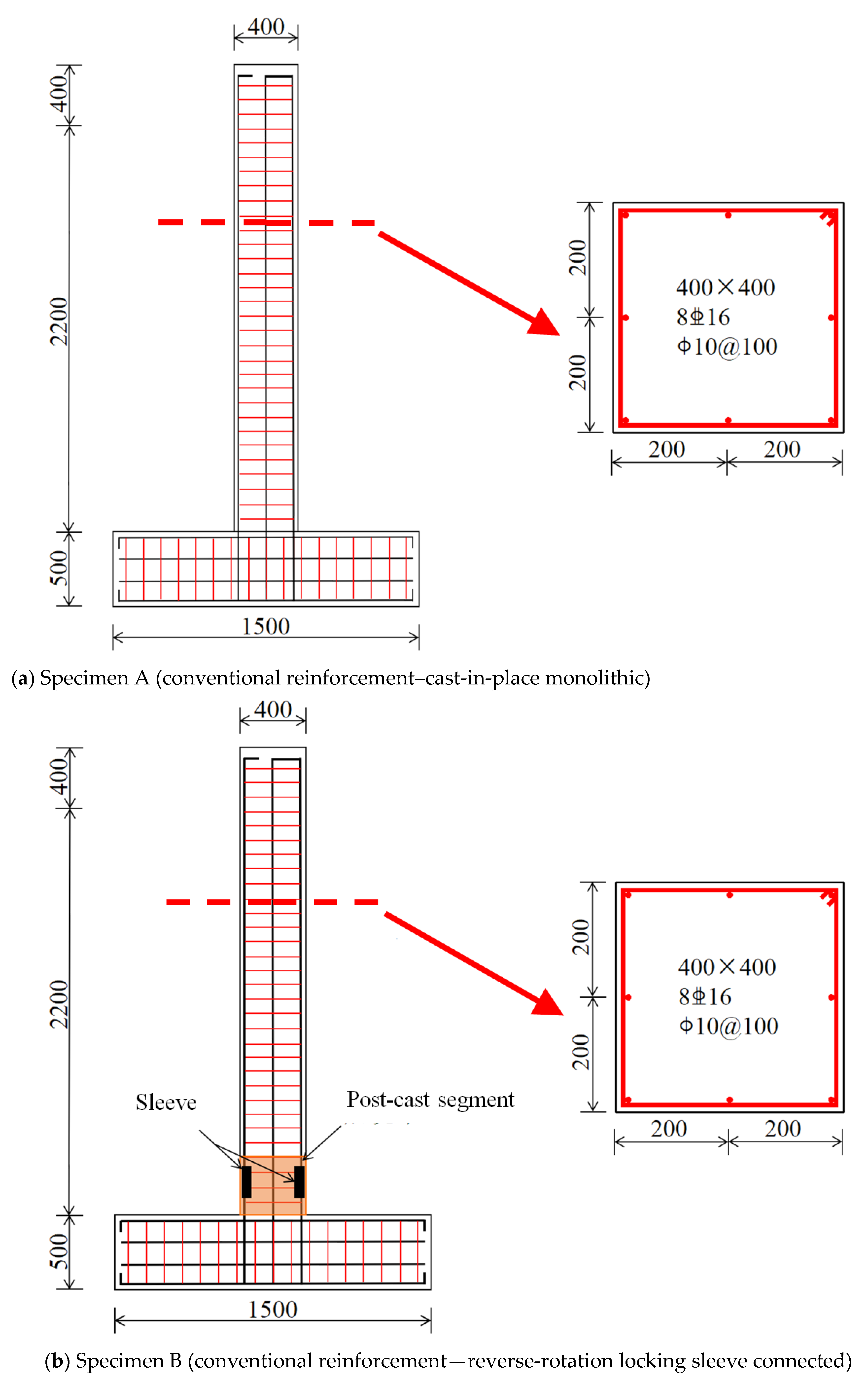
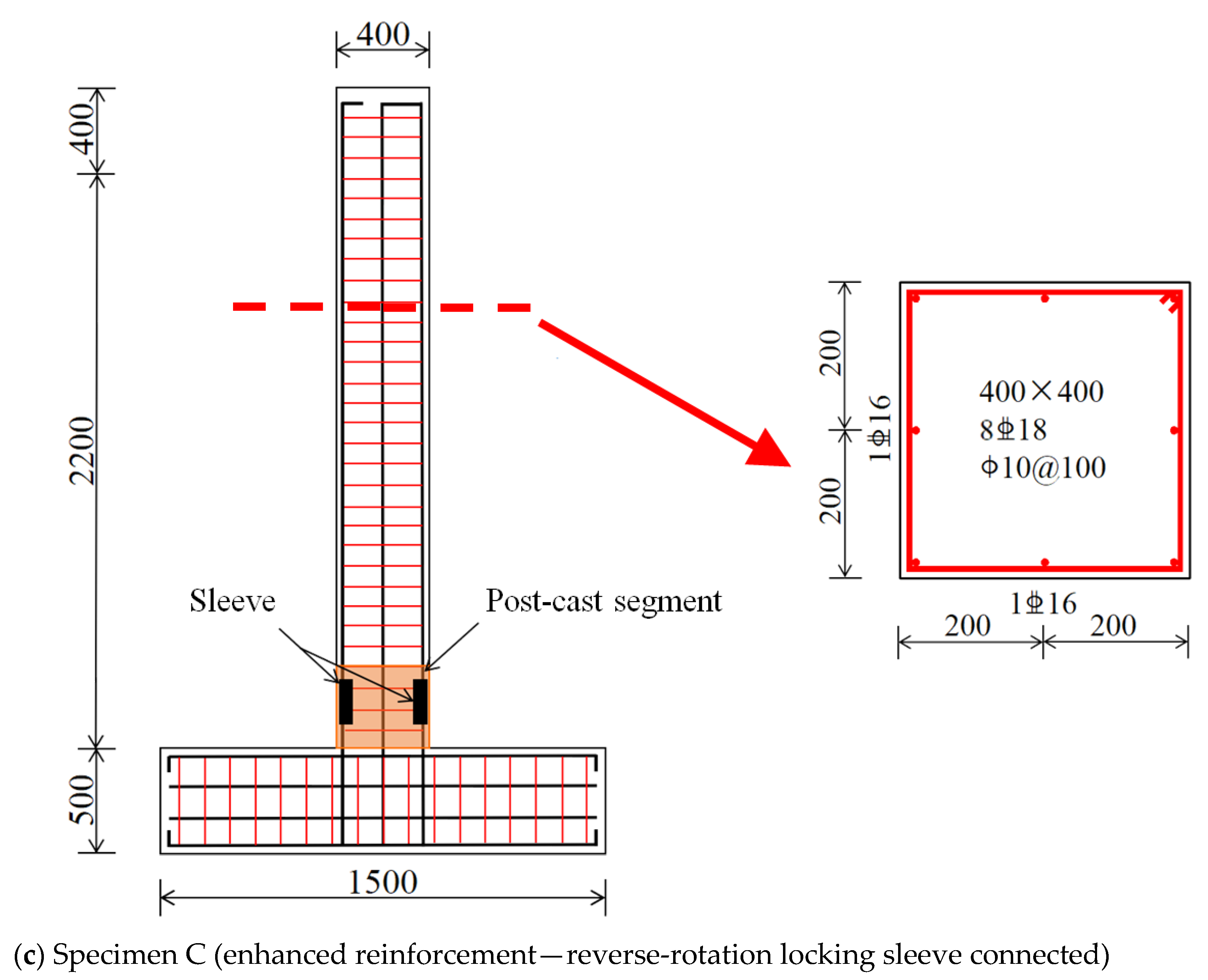
The cross-sectional dimensions of the reinforced concrete used in the quasi-static tests were 400 mm × 400 mm, with a height of 2500 mm; three types were categorized according to different connection methods and reinforcement configurations as follows: conventionally reinforced–cast-in-place monolithic (Specimen A), conventionally reinforced–reverse-rotation locking sleeve connected (Specimen B), and heavily reinforced–reverse-rotation locking sleeve connected (Specimen C). The main body was cast using C35 concrete, while the post-cast segment of the reverse-rotation locking sleeve was cast using C40 concrete; the determination of concrete strength grades was based on the requirements for joint zone concrete strength specified in the “Technical Standard for Prefabricated Concrete Buildings” [30], while also considering compatibility with practical engineering applications. The conventional reinforcement of the specimens consisted of 8C16 longitudinal bars, and the heavy reinforcement consisted of 8C18 longitudinal bars, with stirrups of A10@100 used in all cases; this reinforcement scheme was designed to consider the influence of different reinforcement ratios on joint performance while ensuring comparability among the specimens. Foundation blocks connected to specimen bases measured 500 mm × 500 mm in cross-section with a 1500 mm length. Quasi-static testing arrangements and reinforcement schematics are depicted in Figure 3.
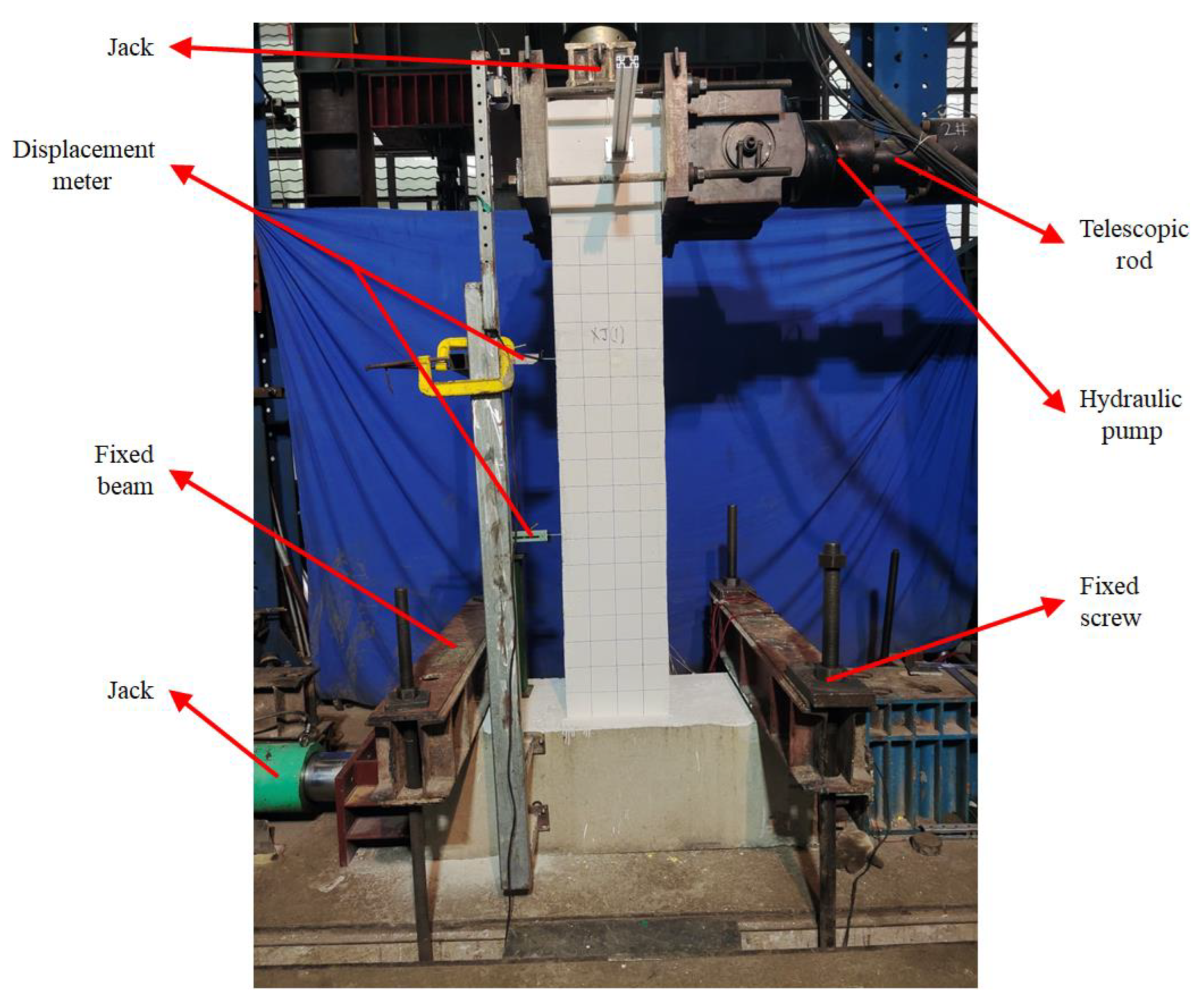
Prior to quasi-static testing, foundation blocks connected to specimen bases were restrained laterally by jacks at both ends. Steel beams were clamped against foundation sides and anchored to the ground with high-strength rods. Constant vertical preload was then applied to specimen tops via jacks. The preload magnitude was determined per GB 50011-2010 [31], corresponding to a 0.3 axial compression ratio. This ensured structural ductility requirements while enhancing seismic safety and stability. Finally, thick steel plates connected to hydraulic loading systems were fixed to the specimen’s top sides. Displacements at mid-height and bottom were recorded by dial indicators, whereas top displacements were automatically measured by hydraulic systems. Installation and fixation arrangements for quasi-static testing are depicted in Figure 4.
Quasi-static testing applied horizontal cyclic loads to specimen sides via telescopic rods connected to hydraulic pumps. Displacement-controlled loading was implemented, with controlled displacements per level calculated by multiplying loading height (2100 mm from base) by tilt angles. Tilt angles and corresponding controlled displacements are listed in Table 1. During testing, each horizontal displacement level underwent one cycle; after crack initiation, each level underwent three cycles. Loading ceased when horizontal load values dropped to 85% of peak capacity or upon specimen failure, concluding the test.

4. Discussions and Results

4.1. Specimen Failure Modes

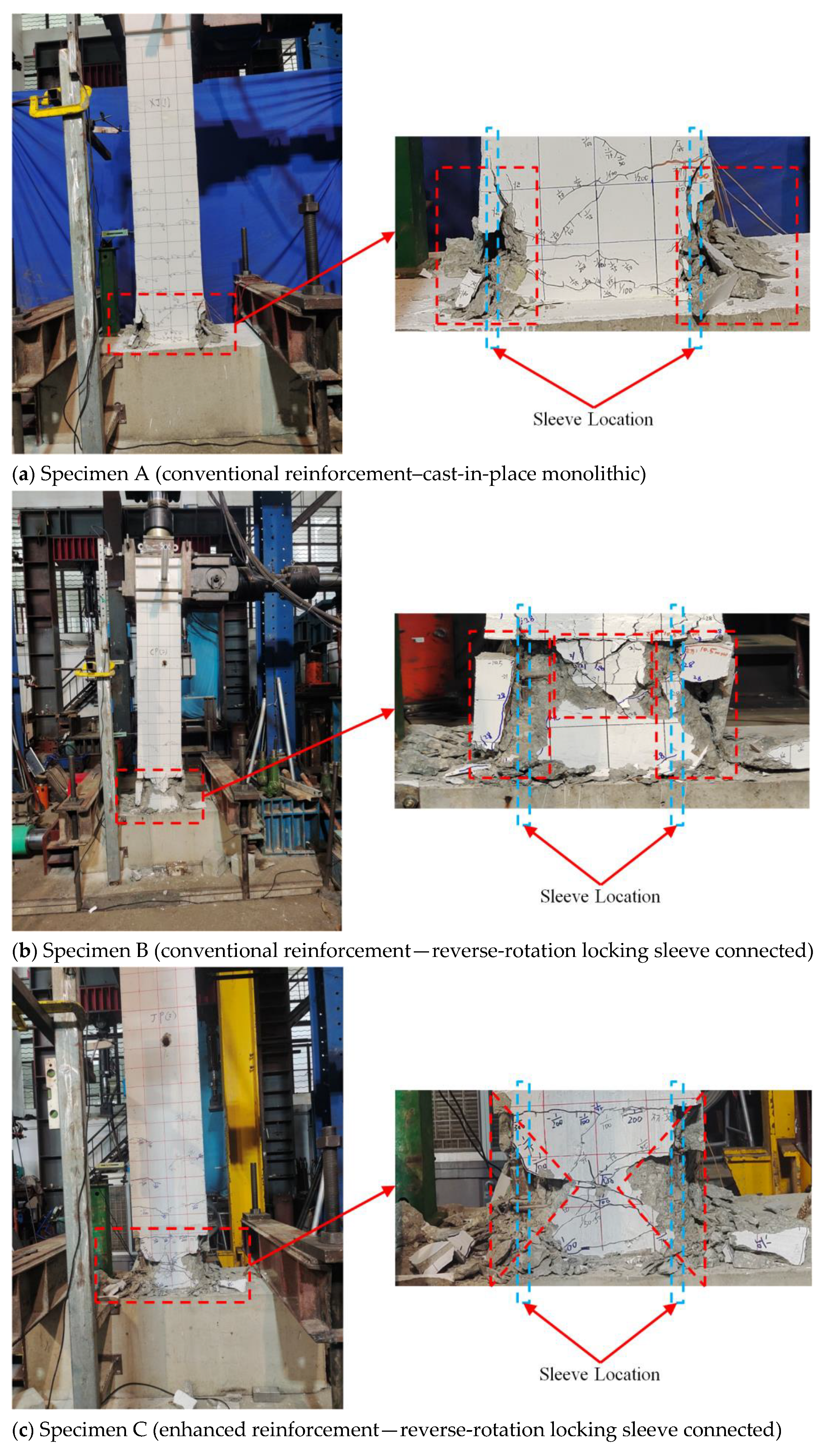
The differences in the failure modes of the specimens can directly reflect the influence of different connection methods and reinforcement configurations on the mechanical performance of the specimens. During the quasi-static test, when the horizontal displacement of Specimen A reached 7 mm, horizontal cracks were first observed at the base of the column, corresponding to a peak load of 93.9 kN; thereafter, each level of horizontal displacement was cycled three times. As the displacement increased, the cracks gradually curved and extended further. During the first cycle at a horizontal displacement of 105 mm, concrete failure occurred, the specimen lost its load-bearing capacity, loading was stopped, and the test was terminated. The specific failure mode is shown in Figure 5a. The failure zone was concentrated at the base of the column, where the outer concrete was crushed and spalled off, while the core concrete in the central region remained relatively intact with a low degree of damage, exhibiting characteristics typical of a ductile flexural failure mode.
For Specimen B, when the horizontal displacement reached 10.5 mm, flexural cracks were first observed at the base of the column, corresponding to a peak load of 134.97 kN, which represents a 43.7% increase compared to Specimen A; thereafter, each level of horizontal displacement was cycled three times. As the displacement increased, the flexural cracks extended toward the interface between the sleeve and the concrete, and propagated rapidly along the threaded interface of the sleeve. During the second cycle at a horizontal displacement of 70 mm, shear slip occurred at the sleeve-concrete interface, leading to specimen failure; loading was subsequently stopped, and the test was terminated. The specific failure mode is shown in Figure 5b. The failure zone was concentrated in the sleeve and surrounding concrete at the column base, where the outer part and part of the core concrete exhibited significant local crushing and spalling, and noticeable wear was observed on the sleeve threads. The overall degree of damage was relatively high, demonstrating characteristics typical of an interface shear failure mode. Compared to Specimen A, cracking occurred later in Specimen B, indicating that during the early stage of the test, the seismic energy dissipation capacity of Specimen B was stronger than that of Specimen A. However, as the test progressed, Specimen B failed at 70 mm, indicating that during the intermediate and late stages of the test, the seismic energy dissipation capacity of Specimen B decreased significantly and rapidly, leading to abrupt failure. This was attributed to stress concentration in the sleeve-concrete interface region, which promoted the rapid development of microcracks in the concrete around the threads, ultimately resulting in sectional shear slip.
For Specimen C, when the horizontal displacement reached 7 mm, flexural cracks were first observed at the base of the column, corresponding to a peak load of 100.22 kN, which represents a 6.7% increase compared to Specimen A; thereafter, each level of horizontal displacement was cycled three times. As the displacement increased, but due to the restraining effect of the enhanced reinforcement, the flexural cracks propagated slowly at an approximate 45° angle to the horizontal direction. During the third cycle at a horizontal displacement of 105 mm, shear failure occurred; loading was subsequently stopped, and the test was terminated. The specific failure mode is shown in Figure 5c. The failure zone was concentrated at the base of the column, where the crushed outer concrete was distributed in a triangular pattern, but the degree of damage was significantly less than that of Specimen B; the core concrete in the central region maintained good integrity, the sleeve threads exhibited slight tilting deformation, and the overall degree of damage was moderate, demonstrating characteristics typical of a flexural–shear composite failure mode. The horizontal displacement values corresponding to crack initiation and failure of Specimen C coincided with those of Specimen A, indicating the improving effect of enhanced reinforcement on the failure mode; this suggests that throughout the entire test process, the evolution law of the seismic energy dissipation capacity of Specimen C was essentially consistent with that of Specimen A, meaning Specimen A and Specimen C possessed nearly identical seismic energy dissipation capacities. It should also be noted that localized failure occurred in the central concrete at the base connection of both Specimen B and Specimen C, which may be attributed to the post-cast nature of this region; the differences in the failure morphology of the central concrete are related to the type of longitudinal reinforcement used.

4.2. Hysteretic Curves and Skeleton Curves

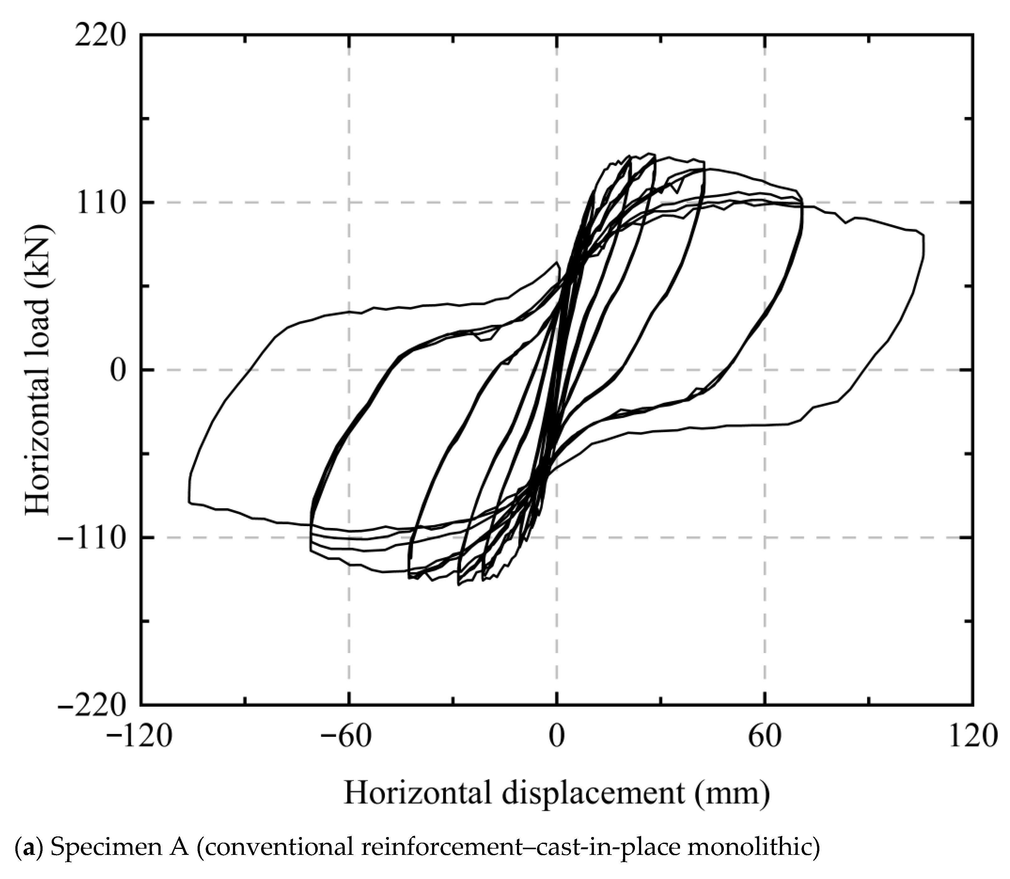
Hysteretic curves represent load–displacement relationships obtained during cyclic lateral loading, reflecting energy dissipation, load-bearing capacity, and stiffness degradation characteristics at each loading stage. Figure 6 reveals closed hysteretic loops for all specimens during initial loading phases due to low applied loads, indicating elastic behavior with minimal energy dissipation and negligible capacity/stiffness degradation. At approximately 12 mm top displacement, hysteretic loop areas gradually increased, signifying enhanced energy dissipation. When displacement reached 18 mm, surface cracking initiated and residual deformations emerged, exhibiting distinct hysteresis loops. With further displacement increases, all specimens developed full and uniform hysteretic loops, demonstrating strong plastic deformation capacity and effective energy dissipation under seismic loading. Beyond this stage, hysteretic loops assumed increasingly “bow-shaped” configurations, indicating pronounced pinching effects. This phenomenon typically occurs during later testing phases, caused by crack opening/closing during shear deformation under cyclic loading, where minor reverse-direction loads induce crack closure and large displacements. Throughout testing, no distinct yield plateau was observed; load–displacement curves reached peak loads rapidly after inflection points, followed by gradual decline until specimen failure.
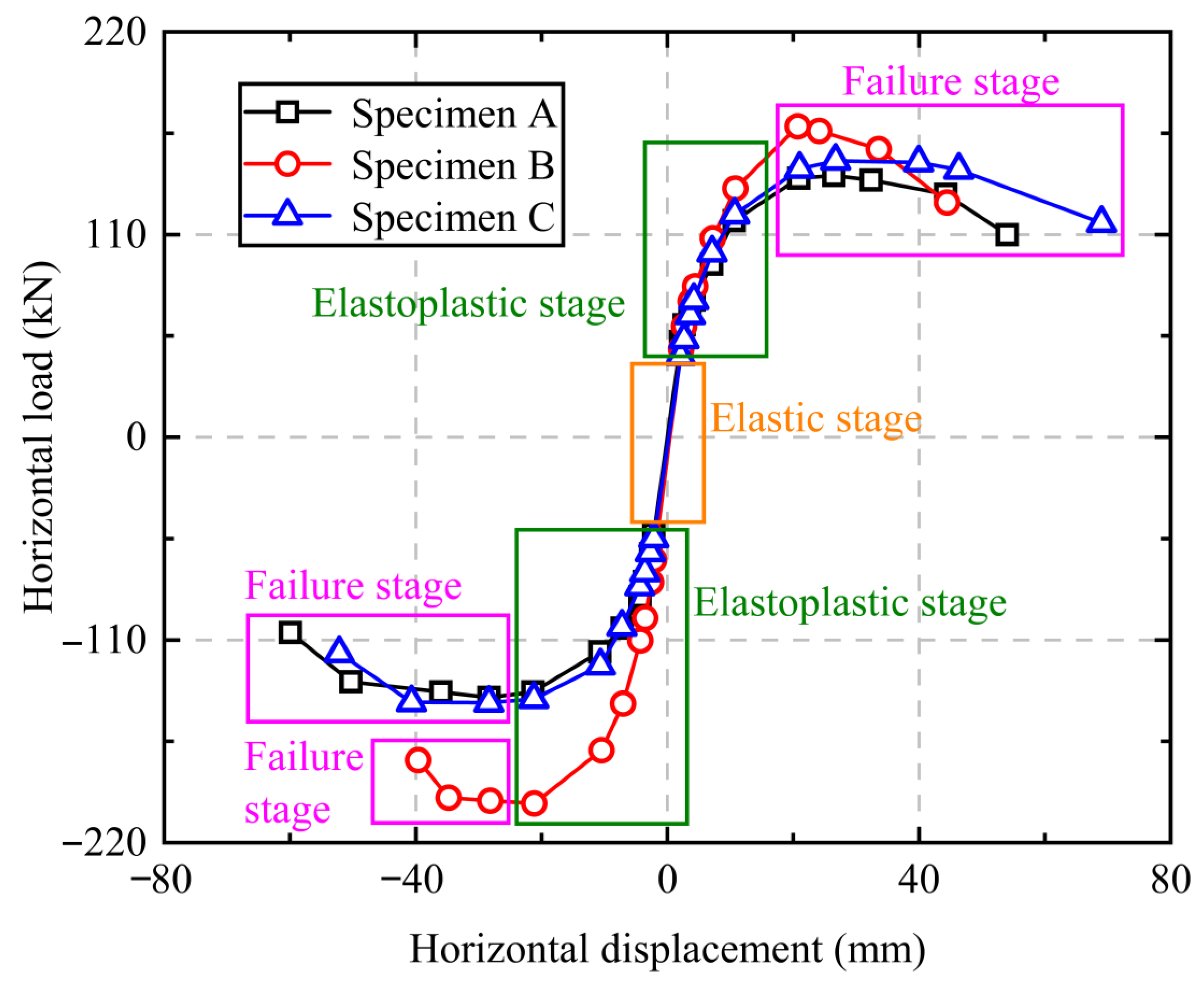
Envelope curves formed by connecting unloading points of hysteretic loops are defined as skeleton curves, reflecting load-bearing capacities, stiffness, and deformation characteristics at each loading cycle [32]. Stiffness governs structural displacement responses and seismic force resistance during earthquakes, constituting a critical factor for deformation control and seismic performance requirements. Figure 7 reveals that all specimens exhibit essentially S-shaped skeleton curves with symmetrical positive/negative loading paths. Each curve displays distinct stages: elastic deformation, elastoplastic deformation, and failure deformation. During initial loading, horizontal loads and displacements were proportional, yielding near-linear skeleton curves where specimens remained elastic with minimal differences. As testing progressed, increasing displacements induced elastoplastic behavior, manifested by curved skeleton curves with gradually decreasing slopes, indicating progressive stiffness degradation. When the peak horizontal load was reached, the horizontal displacement of Specimen B was 28 mm, and the horizontal displacements of Specimens A and C were 21 mm; moreover, the peak horizontal load corresponding to Specimen B was the largest, while the peak horizontal loads of Specimens A and C were essentially consistent. This indicates Specimen B underwent more rapid stiffness degradation and sustained higher short-term peak loads than A and C, demonstrating enhanced brittleness. During failure phases, Specimen B experienced rapid load decline until test termination. Specimens A and C exhibited gradual load reduction with displacement, where Specimen C displayed a slightly more pronounced yield plateau than A, indicating superior ductility. This confirms consistent structural behavior evolution and overall superior seismic performance in Specimen C.
To quantitatively characterize skeleton curve relationships, piecewise functions are recommended as follows:
y = a x ( x 3.5   cm ) b x c ( 3.5 < x 21   cm ) d e x ( x > 21   cm )
where y is the horizontal load (kN), x is the horizontal displacement (mm), and a, b, c, and d are all fitting parameters.
Yield state is considered attained when skeleton curves exhibit distinct inflection points. Corresponding horizontal displacement Δx is denoted as yield displacement; corresponding horizontal load Δy is defined as yield load. Specimen failure is identified when horizontal load declines to 85% of peak load. Corresponding horizontal displacement Δu is termed failure displacement; corresponding horizontal load Δv is designated as failure load (ultimate load), representing structural maximum load-bearing capacity. This constitutes the fundamental safeguard for seismic objectives, preventing structural collapse by maintaining vertical load resistance. Yield and failure state parameters for all specimens are listed in Table 2.
Table 2 data analysis reveals that during positive cyclic loading, compared to Specimen A, Specimen B exhibited a 3.6% reduction in yield load and an 18.7% increase in failure load; Specimen C showed a 13.7% yield load reduction and a 5.5% failure load increase. Under negative cyclic loading, relative to Specimen A, Specimen B demonstrated 55% higher yield load and 40.8% greater failure load; Specimen C displayed 21.2% increased yield load and 2% elevated failure load. These results indicate later attainment of yield and failure states in Specimens B and C compared to A, reflecting overall superior energy dissipation performance in reverse-rotation locking sleeve connections versus monolithic connections. Simultaneously, higher yield and failure loads in Specimens B and C confirm enhanced seismic performance during plastic stages with sleeve connections. This demonstrates failure loads are influenced by both reverse-rotation locking sleeve connections and reinforcement ratios, with greater sensitivity to sleeve connection methods.

4.3. Ductility and Energy Dissipation Capacities

Ductility permits structures to undergo substantial inelastic deformations without brittle failure under seismic action. Seismic energy dissipation through such plastic deformations constitutes a key earthquake resistance mechanism. To evaluate ductility characteristics, the ductility coefficient is adopted for quantitative expression.
Based on Table 2 data, the ductility coefficient μΔ is calculated as follows:
μ Δ = Δ u Δ y
where μΔ denotes the ductility coefficient, Δu represents failure displacement, and Δx indicates yield displacement. Per Equation (2), ductility coefficient values for all specimens are listed in Table 3.
Ductility coefficients for concrete structures are generally required to exceed 3 [33]. Table 3 indicates that under positive cyclic loading, Specimen C exhibits the highest ductility coefficient, followed by Specimen B, with Specimen A demonstrating the lowest value. All specimens exceed the threshold of 3. This confirms that reverse-rotation locking sleeve connections satisfy global ductility requirements. To further quantitatively evaluate the ductility effect of the reverse-rotation locking sleeve connection method, the ductility coefficients μΔ of different node connection techniques for prefabricated building structures are compared and analyzed, as shown in Table 4.
Among them, the positive ductility coefficient of Specimen C, 5.66, is very close to the values reported in references [34,35,36,37], indicating that compared to traditional node connection techniques for prefabricated building structures, the reverse-rotation locking sleeve connected to Specimen C possesses excellent plastic deformation dissipation capacity.
However, under negative cyclic loading, Specimens B and C exhibit lower ductility coefficients than Specimen A, suggesting potential for improvement in sleeve connection design. The phenomenon of lower ductility coefficients of Specimens B and C under reverse cyclic loading is mainly influenced by two aspects: firstly, the inherent characteristics of the connection design, where the reverse-rotation nut is prone to minor slippage under reverse cyclic loading, leading to non-uniform stress distribution; secondly, the influence of loading history, where positive cyclic loading precedes reverse cyclic loading, resulting in different cumulative damage in the material, causing differences in crack development and dynamic performance under compressive and tensile states. Cross-sectional dimensions of reinforcement constitute a critical factor influencing ductility. A quantitative relationship between ductility coefficients and reinforcement intensification ratios is established, yielding the following empirical formula:
η = A R A A × 100 %
μ Δ = 3.56 + 15.8 η
where η denotes reinforcement intensification ratio, A represents total cross-sectional area of longitudinal reinforcement, and AR signifies total cross-sectional area of enhanced longitudinal reinforcement. Substituting specimen B and C parameters into Equation (3) yields η = 13.3%. The fitting correlation coefficient for Equation (4) reaches 0.97. This formulation enables provision of critical guidance and effective recommendations for practical engineering applications of reverse-rotation locking sleeve connections.
Energy dissipation capacity constitutes a critical metric for evaluating structural seismic performance. Per JGJ/T 101-2015 [38], the equivalent viscous damping coefficient he quantitatively characterizes equivalent energy dissipation capacity during nonlinear response phases. This parameter serves as a key simplification for considering actual nonlinear energy dissipation behaviors in seismic analysis and design.
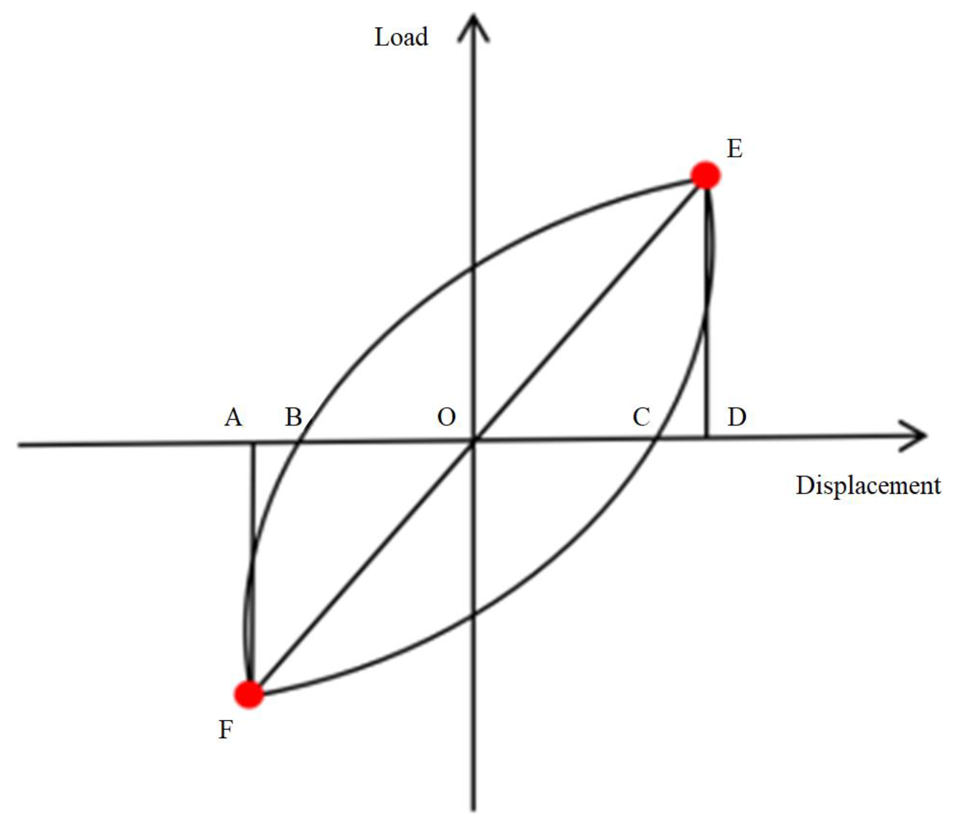
The calculation schematic for the equivalent viscous damping coefficient he is illustrated in Figure 8, with the computation method as follows:
h e = 1 2 π S ( E B F C ) S ( Δ A F O + Δ E D O )
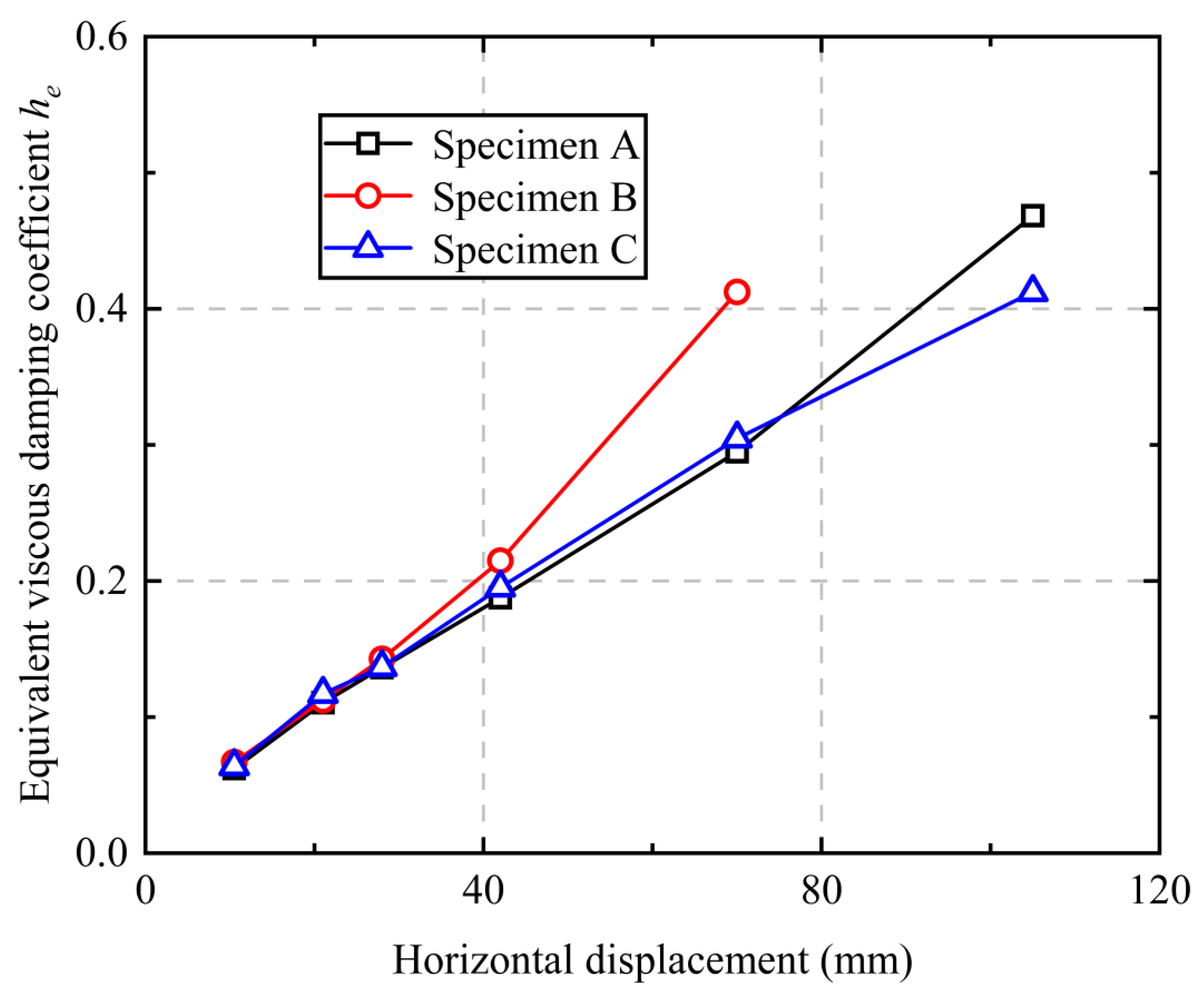
where he denotes the equivalent viscous damping coefficient, and S represents polygon area. Based on Figure 6 and Figure 8 and Equation (5), equivalent viscous damping coefficient he versus horizontal displacement Δx curves for quasi-static testing specimens are obtained, as illustrated in Figure 9.
Figure 9 indicates that the equivalent viscous damping coefficient he exhibits exponential variation with increasing horizontal displacement Δx, fitted by he = a(1 − (Δx)b), where a and b are fitting parameters. During quasi-static cyclic loading prior to 28 mm displacement, he values for all specimens essentially coincided, indicating nearly identical energy dissipation capacities in initial testing phases. Beyond this displacement, divergence emerged: Specimens B and C both achieved he = 0.41 before failure, but Specimen C sustained larger displacements, demonstrating superior energy dissipation. Both exhibited approximately 0.06 lower he than Specimen A [39]. This confirms reverse-rotation locking sleeve connections do not compromise energy dissipation and require smaller displacements for equivalent dissipation effects. By comparing the variables and parameters in Table 3 and Figure 9, it can be observed that the ductility coefficient of Specimen C (positive 5.66) is significantly higher than that of Specimen B (positive 3.56) and represents a 10.3% increase compared to Specimen A (positive 5.13); the energy dissipation capacity exceeded that of Specimen A after the lateral displacement exceeded 28 mm. Enhanced reinforcement in Specimen C increased sectional flexural rigidity, effectively delaying crack propagation and promoting uniform plastic deformation for improved ductility. Strengthened rebars in sleeve-cast zones reduced interfacial slip in post-cast concrete, forming triangular failure zones (Figure 5c) that enabled fuller energy dissipation. It is noteworthy that the maximum equivalent viscous damping coefficient he in Figure 9 and references [34,36] was slightly less than 0.5, demonstrating high consistency and proving the rationality of this study along with its certain promotional and practical application value.

4.4. Load-Bearing Capacity Degradation and Stiffness Degradation

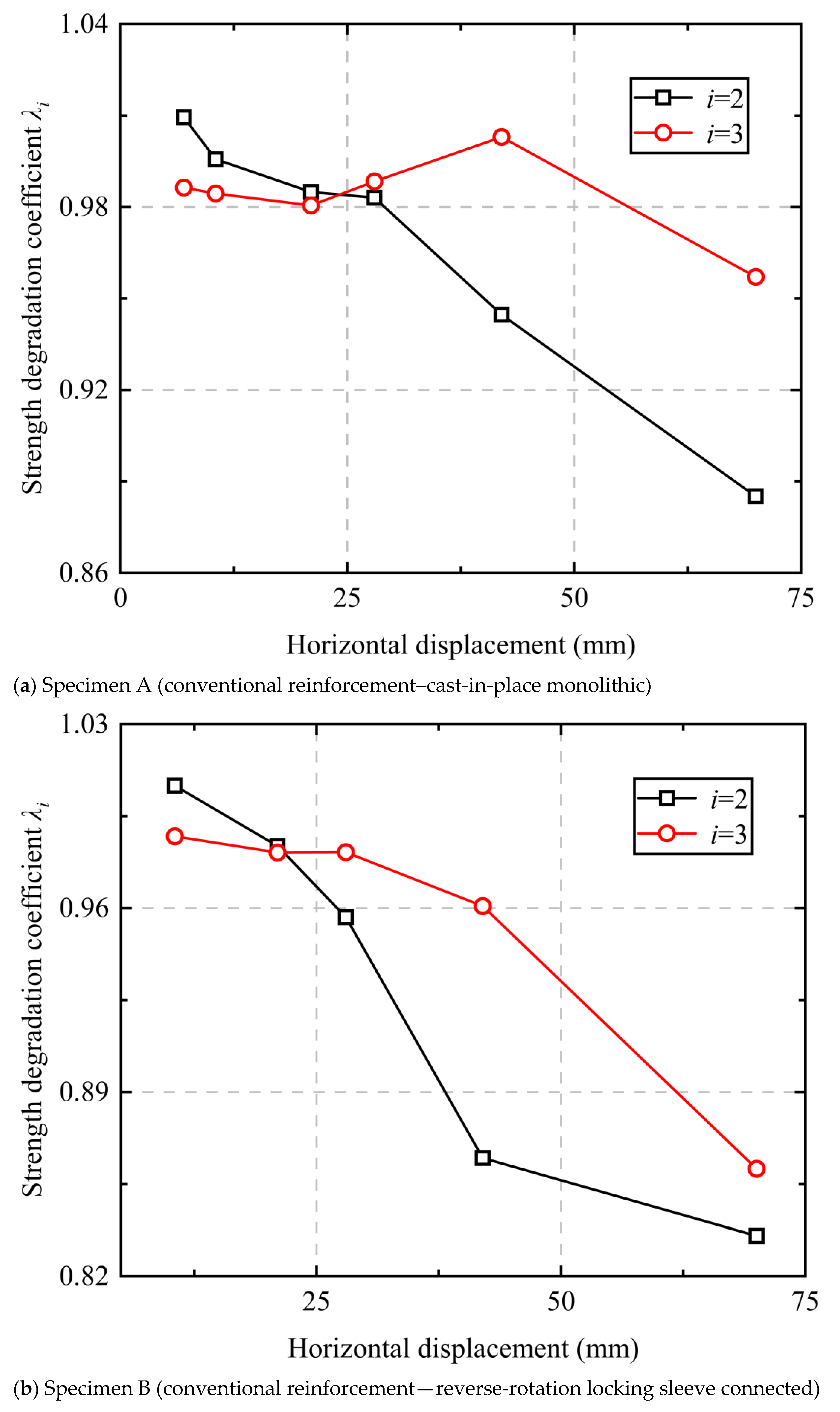
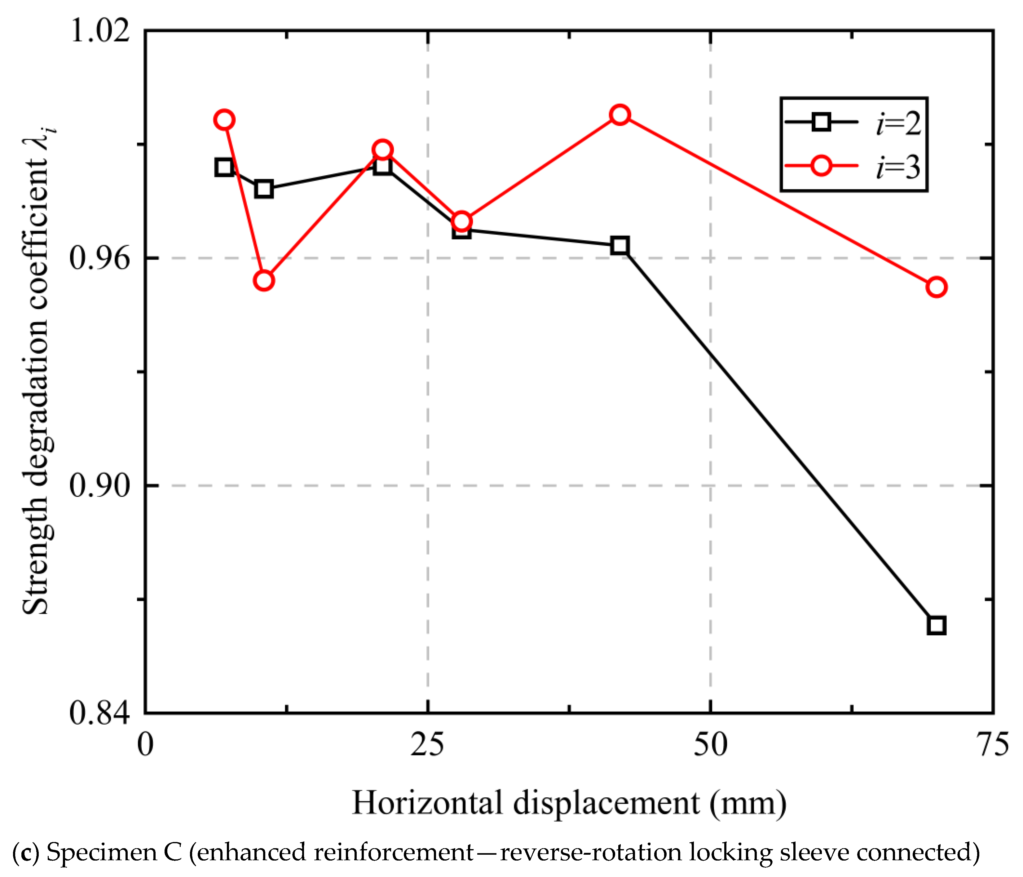
Load-bearing capacity degradation characteristics of specimens are quantified by load-bearing capacity degradation coefficients; stiffness degradation characteristics are quantified by stiffness degradation coefficients. Per JGJ/T 101-2015 [38], expressions for degradation coefficients λi (load-bearing capacity) and ki (stiffness) are defined as follows:
λ i = F j i F j i 1
where i denotes cycle number, λi represents load-bearing capacity degradation coefficient; F j i signifies peak load at the i-th cycle during j-th loading level; and F j i 1 indicates peak load at the (i−1)-th cycle during j-th loading level.
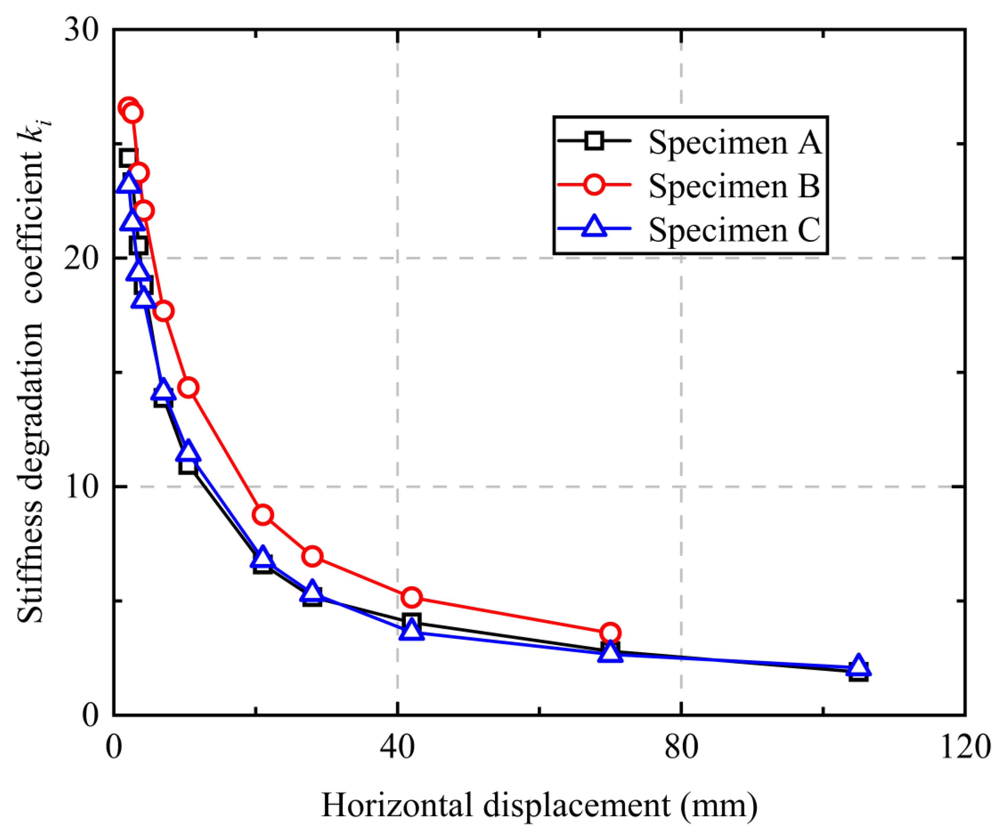
k i = + F i + F i + X i + X i
where ki denotes the stiffness degradation coefficient; +Fi and −Fi represent positive and negative directional peak loads at the i-th cycle, respectively; and +Xi and −Xi correspond to horizontal displacements at respective peak loads at the i-th cycle. Based on Figure 6 and Equation (6), load-bearing capacity degradation curves for quasi-static testing specimens are plotted in Figure 10.
Figure 10 demonstrates degradation coefficients fluctuating between 0.83 and 1.01 for all specimens, manifesting a decreasing trend with increasing horizontal displacement. Overall degradation progressed gradually with low severity. Beyond 30 mm displacement, degradation trends of Specimens A and C converged. During the third cycle at the final displacement level, degradation coefficients for Specimens A and C both approximated 0.96, within the normal range of 0.9–1.0 [40,41]. This indicates consistent load-bearing capacity degradation behavior between reverse-rotation locking sleeve specimens and monolithic specimens under cyclic loading, with minimal capacity variation. Reverse-rotation locking sleeve connected specimens maintain stable strength during elastoplastic deformation stages, demonstrating favorable seismic performance.
Based on Figure 6 and Equation (7), stiffness degradation curves and normalized stiffness degradation coefficient curves for quasi-static testing specimens are obtained, illustrated in Figure 11 and Figure 12, where κ denotes the normalized stiffness degradation coefficient ratio, defined as ki/kmax. Stiffness degradation coefficient trends are essentially identical across all specimens. During the elastic stage (Δx < 3.5 mm), stiffness degradation coefficients decrease rapidly. Throughout the elastoplastic stage (3.5 ≤ Δx ≤ 21 mm), degradation rate deceleration occurs progressively with crack propagation and concrete spalling. During the failure deformation stage (Δx > 21 mm), degradation rates stabilize. This demonstrates consistent stiffness degradation characteristics between reverse-rotation locking sleeve specimens and monolithic specimens, indicating favorable seismic performance.

5. Conclusions

To meet the safety requirements of joints in prefabricated structures, this paper comprehensively considers the advantages and disadvantages of various joint connection methods, such as sleeve connections and bolted connections, and originally proposes a reverse-rotation locking sleeve connection method, which is a composite connection mechanism combining mechanical locking and post-cast concrete. This connection method breaks through the limitations of traditional technologies, eliminates the need for grouting and bolt quality inspection, can effectively reduce comprehensive costs, provides an effective solution for the promotion and application of prefabricated structures, and has the advantages of simple construction, convenient installation, strong adaptability, and excellent mechanical performance, showing broad application prospects in engineering. Based on systematic quasi-static tests, a series of dynamic parameter indicators were obtained. Through comparative analysis, the dynamic performance of the reverse-rotation locking sleeve connection method was evaluated, and the following main conclusions were drawn:
  • Compared with traditional connection methods, the reverse-rotation locking sleeve connection demonstrates excellent comprehensive performance. In terms of failure modes, Specimen B exhibited more severe damage with potential stress concentration risks under strong earthquakes, while Specimen A showed the best integrity. Specimens A and C possessed nearly identical seismic energy dissipation capacities; however, Specimen B displayed significant rapid degradation in seismic energy dissipation capacity during the intermediate and late stages of testing, making Specimen C more suitable for high-intensity scenarios.
  • The hysteretic curves of Specimens B and C were relatively full without obvious yield platforms, enabling greater energy absorption during seismic events; all three specimens exhibited S-shaped skeleton curves, with Specimens A and C reaching their peak loads at a lateral displacement of 21 mm, while Specimen B reached its peak load at 28 mm; compared to the cast-in-place monolithic Specimen A, the reverse-rotation locking sleeve connected Specimens B and C showed increases in ultimate load under positive cyclic loading by 18.7% and 5.5%, respectively, and under negative cyclic loading by 40.8% and 2.0%, respectively, indicating that the reverse-rotation locking sleeve connection method exhibits superior seismic performance during the plastic stage.
  • The ductility coefficients of all three specimens met the requirement of being greater than 3.0 (Specimen A: 5.13; Specimen B: 3.56; Specimen C: 5.66), with Specimen C showing a 10.3% improvement over Specimen A, indicating that the reverse-rotation locking sleeve connection specimens possess favorable ductility and can effectively prevent sudden structural failure; analysis revealed that the equivalent viscous damping coefficient of Specimen C was approximately 0.06 higher than that of Specimen A, meaning Specimen C exhibited superior energy dissipation capacity compared to Specimen A, demonstrating that the reverse-rotation locking sleeve connection method can effectively absorb energy and enhance the seismic and energy dissipation characteristics of the specimens.
  • The load-bearing capacity degradation coefficients of all three specimens fluctuated between 0.83 and 1.01, showing an initial stable phase followed by a gradual declining trend; the stiffness degradation coefficients exhibited rapid initial decline, followed by a deceleration in the attenuation rate, and eventual stabilization. This indicates that the reverse-rotation locking sleeve connection specimens can maintain stable strength and favorable seismic performance during the plastic deformation stage.

Author Contributions

X.-M.T.: Funding acquisition and project administration. R.-G.G.: Conceptualization and writing—review and editing. C.-H.H.: Investigation and supervision. R.-Q.L.: Data curation and writing—original draft. K.G.: Formal analysis and writing—original draft. X.-F.Z.: Funding acquisition and methodology. All authors have read and agreed to the published version of the manuscript.

Funding

This study was supported by the Guangdong Provincial Key Laboratory of Modern Civil Engineering Technology (2021B1212040003).

Data Availability Statement

Data will be made available upon request. Any questions should be addressed to the corresponding author.

Acknowledgments

The authors thank all personnel who helped with this study.

Conflicts of Interest

Author Xue-Mei Tang was employed by the company Guangzhou Electric Power Design Institute Co., Ltd., Author Xiao-Feng Zhang was employed by the company China Energy Engineering Group Guangdong Electric Power Design Institute Co., Ltd. The remaining authors declare that the research was conducted in the absence of any commercial or financial relationships that could be construed as a potential conflict of interest.

References

  1. Wang, C.; Li, X.; Li, X. Construction technology for connecting prefabricated components and vertical cast-in-situ belt reinforcement in prefabricated buildings. Build. Technol. 2024, 55, 1868–1870. [Google Scholar]
  2. Tang, T.; Song, J.; Zhu, C.; Peng, L.; Lei, X. Research on energy dissipation and seismic reduction of joints in prefabricated concrete frame-shear wall structures. Build. Struct. 2023, 53 (Suppl. S2), 861–866. [Google Scholar]
  3. Du, Y.; Sun, X.; Yang, J.; Quan, Y.; Bian, D. Research on detection method for grouting fullness of sleeves in prefabricated structures based on piezoelectric principle. J. Railw. Sci. Eng. 2024, 21, 860–872. [Google Scholar]
  4. You, J.; Jia, H.; Tang, C.; Yang, H.; Mao, J. Relaxation behavior of bolt tension force in concrete member connections in cold regions. Shanxi Archit. 2024, 50, 6–9+15. [Google Scholar]
  5. Zang, X.; Zhu, Z. Quasi-static test study on prefabricated shear walls with spiral stirrup-constrained bellows grouted connection. Constr. Technol. 2018, 47, 82–87. [Google Scholar]
  6. Chouery, E.; Fan, K.; Jia, L. Research status of seismic performance and design methods for symmetric and asymmetric friction energy dissipation connections. Eng. Mech. 2021, 38, 22–37+49. [Google Scholar]
  7. Zhou, Z.; Pan, Z. Seismic performance analysis of fully prefabricated RCS hybrid structure with friction splicing energy dissipation joints. Build. Struct. 2014, 44, 51+72–76. [Google Scholar]
  8. Han, J.; Zhang, H.; Qiao, Y. Experimental study on hysteretic behavior of friction dampers with sliding long hole and high-strength bolts. J. Build. Struct. 2018, 39 (Suppl. S2), 315–320. [Google Scholar]
  9. Xu, X.; Kong, Z.; Sun, W.; Yu, Z.; Fan, X. Research on seismic performance and mechanical model of T-shaped steel energy dissipation hinge dampers. Earthq. Eng. Eng. Vib. 2024, 44, 136–147. [Google Scholar]
  10. Arapati, A.; Chen, G. A review of connection methods for joints in prefabricated concrete structures. Struct. Eng. 2020, 36, 224–233. [Google Scholar]
  11. Yan, L.; Wu, T.; Tuo, W.; Wei, Y.; Zhao, W.; Zheng, Y. A review of research progress on connection joints of prefabricated structures. Build. Sci. 2020, 36, 126–132. [Google Scholar]
  12. Ou, W.; Liu, K.; Ma, G. A review of research on connection joints of prefabricated frames. Constr. Sci. Technol. 2020, 401, 59–62. [Google Scholar]
  13. Liu, L.; Xiao, J. Research progress on grouted sleeve connection of steel bars. J. Build. Struct. 2023, 44, 235–247. [Google Scholar]
  14. Ling, J.; Abd, A.; Ibrahim, I.; Abdul, Z. Tensile capacity of grouted splice sleeves. Eng. Struct. 2016, 111, 285–296. [Google Scholar] [CrossRef]
  15. Wang, H.; Wang, G. Research on joints of fully prefabricated concrete structures. Bricks Tiles 2024, 7, 91–94. [Google Scholar]
  16. Pan, Z.; Bao, X.; Wang, S. Seismic performance and structural parameters of RCS beam-column joints with asymmetric friction connections. J. Jiangsu Univ. Sci. Technol. (Nat. Sci. Ed.) 2024, 38, 91–97. [Google Scholar]
  17. Zhao, B.; Lü, X.; Liu, L. Experimental study on seismic performance of fully prefabricated concrete beam-column composite members. Earthq. Eng. Eng. Vib. 2005, 01, 81–87. [Google Scholar]
  18. Zhang, W.; Shan, H.; Han, X. Experimental study on shear performance of prefabricated gutters with high-strength bolt cone hole grouting connections. Build. Struct. 2024, 54, 132–137. [Google Scholar]
  19. Wu, D.; Yang, Y.; Li, C. Experimental study on mechanical performance of bolted connections in prefabricated reinforced concrete beams. J. Water Resour. Archit. Eng. 2023, 21, 146–151+186. [Google Scholar]
  20. Zhao, L.; Hu, S.; Qi, H.; Nie, Y.; Tao, X.; Zhao, X.; Luo, L. Experimental study on seismic performance of square steel tube concrete splice columns with novel corrugated pipe connections. Build. Struct. 2024, 54, 1–7. [Google Scholar]
  21. Xu, Y.; Wei, K.; Li, M. Seismic performance study on precast pier-cap beam joints based on bundled bars–grouted corrugated duct connections. China Civ. Eng. J. 2023, 56, 12–22. [Google Scholar]
  22. Yan, X.; Zhang, H.; Yang, T.; He, W.; Zhang, X. Seismic performance analysis of precast bridge piers with grouted corrugated duct connections. Spec. Struct. 2025, 42, 87–91. [Google Scholar]
  23. Liu, R.; Wu, J.; Yan, G.; Wang, H. Experimental study on seismic performance of friction-bearing energy dissipation connections for beam-column joints. Eng. Mech. 2025, 42, 146–157. [Google Scholar] [CrossRef]
  24. Yang, Y.; Diao, Y.; Ren, Y.; Liu, Y.; Liu, X. Seismic performance study on replaceable spliced connection joints with friction energy dissipation components. Prog. Steel Build. Struct. 2023, 25, 22–34. [Google Scholar]
  25. Xu, L.; Huang, C.; Xie, X. Performance study on self-centering braced steel frames with friction assembled joints. J. Vib. Eng. 2024, 37, 1239–1249. [Google Scholar]
  26. Zhou, Q. Study on Mechanical Characteristics and Shear Performance of Joints in Hinged Prefabricated Frame-Anchor Structures. Master’s Thesis, Changsha University of Science & Technology, Changsha, China, 2022. [Google Scholar]
  27. Wang, H. Research on Seismic Performance and Design Methods of Prefabricated Concrete Beam-Column Hinged Frame-Shear Wall Systems. Master’s Thesis, Shandong Jianzhu University, Jinan, China, 2021. [Google Scholar]
  28. Zhang, J.; Ma, Z.; Liang, H. Numerical analysis of seismic performance of energy-dissipating steel hinged joints in prefabricated concrete frames. Build. Technol. 2018, 49 (Suppl. S1), 188–190. [Google Scholar]
  29. Wang, Y.; Gao, G.; Hong, Z.; Wang, J.; Liu, T. Fire resistance performance analysis of bolted connections in prefabricated beam-column joints. J. Shenyang Jianzhu Univ. (Nat. Sci.) 2024, 40, 658–667. [Google Scholar]
  30. GB/T 51231-2016; Technical Standard for Prefabricated Concrete Buildings. Anhui Jianzhu University: Hefei, China, 2016.
  31. GB/T 50011-2010; Code for Seismic Design of Buildings. Ministry of Housing and Urban-Rural Development of the People’s Republic of China: Beijing, China, 2010.
  32. Li, C.; Qi, Y.; Xu, C.; Sun, J. Study on mechanical behavior of T-stub connections between square concrete-filled steel tubular columns and steel beams. J. Build. Struct. 2017, 38 (Suppl. S1), 409–416. [Google Scholar]
  33. Shen, P. Explanation of Difficult Problems in High-Rise Building Structures: Prepared According to Code JGJ3-2010, 2nd ed.; China Architecture & Building Press: Beijing, China, 2011. [Google Scholar]
  34. Li, J.; Xia, Z.; Yu, Z. Bidirectional quasi-static test study on prefabricated concrete double-column piers with grouted sleeve connections. Earthq. Eng. Eng. Vib. 2020, 40, 193–203. [Google Scholar]
  35. Liu, X.; Pu, S.; Xu, A.; Ni, Z.; Zhang, A.; Ynag, Z. Experimental study on static and seismic behavior of fully bolted connections in modular prefabricated multi-story steel structures. J. Build. Struct. 2015, 36, 43–51. [Google Scholar]
  36. Ge, J.; Xia, Z.; Jiang, H. Bidirectional quasi-static test on prefabricated bridge piers with grouted corrugated ducts. China J. Highw. Transp. 2018, 31, 221–230+266. [Google Scholar]
  37. Wei, R. Quasi-static test study on new prefabricated rotating friction beam-column cross-shaped energy dissipation joints. Fujian Archit. 2024, 5, 104–110. [Google Scholar]
  38. JGJ/T 101-2015; Specification for Seismic Test of Buildings. Ministry of Housing and Urban-Rural Development of the People’s Republic of China: Beijing, China, 2015.
  39. Zhao, H. Steel and Concrete Composite Structures; Science Press: Beijing, China, 2001. [Google Scholar]
  40. Cao, F.; Lu, Z.; Zhao, G.; Lu, Y. Experimental study on seismic performance of interior joints in PEC column-steel beam frames. J. Build. Struct. 2020, 41, 30–41. [Google Scholar]
  41. Zhang, Z.; Chen, D.; Jiang, Z.; Zhang, Q. Experimental study on seismic performance of steel frame-cold-formed thin-walled steel shear wall structures. Prog. Steel Build. Struct. 2022, 24, 11–19. [Google Scholar]
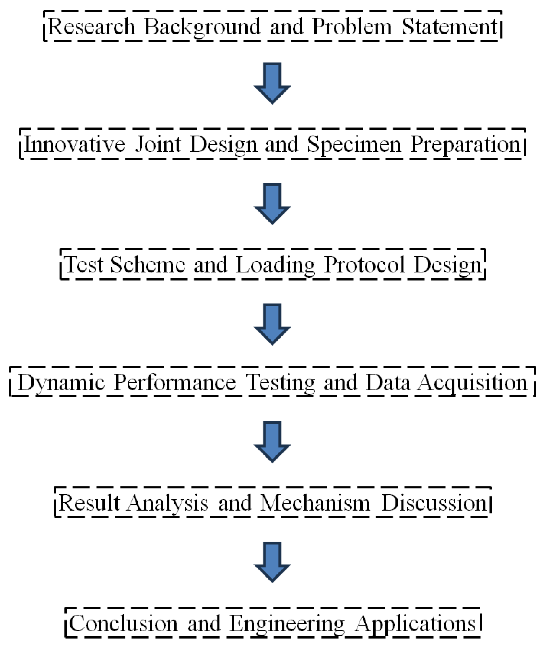
Figure 1. Schematic diagram of the research workflow.
Buildings 15 03790 g001
Figure 2. Reverse-rotation locking sleeve connection schematic.
Buildings 15 03790 g002
Figure 3. Quasi-static testing specimens and reinforcement schematics.
Buildings 15 03790 g003aBuildings 15 03790 g003b
Figure 4. Quasi-static testing specimen installation and fixation schematic (In the figure, XJ(1) and 2# designate Specimen A and Telescopic Hydraulic Cylinder #2 in the laboratory during the test, respectively).
Buildings 15 03790 g004
Figure 5. Failure patterns of quasi-static testing specimens (In the figure, XJ(1), CP(2), and JP(3) correspond to Specimen A, Specimen B, and Specimen C, respectively, during the testing process).
Buildings 15 03790 g005
Figure 6. Hysteretic curves of quasi-static testing specimens.
Buildings 15 03790 g006aBuildings 15 03790 g006b
Figure 7. Skeleton curves of quasi-static testing specimens.
Buildings 15 03790 g007
Figure 8. Load–displacement schematic for quasi-static testing (In the figure, O represents the origin of coordinates; A and D denote the maximum negative displacement and maximum positive displacement, respectively; E and F indicate the load value corresponding to displacement D and the load value corresponding to displacement A, respectively; B and C signify the positive displacement value and negative displacement value when the load value is zero, respectively).
Buildings 15 03790 g008
Figure 9. Equivalent viscous damping coefficient he—horizontal displacement curves for quasi-static testing specimens.
Buildings 15 03790 g009
Figure 10. Load-bearing capacity degradation curves of quasi-static testing specimens.
Buildings 15 03790 g010aBuildings 15 03790 g010b
Figure 11. Stiffness degradation curves of specimens.
Buildings 15 03790 g011
Figure 12. Normalized stiffness degradation coefficient curves of specimens.
Buildings 15 03790 g012
Table 1. Controlled displacements for test loading.
Control Displacement (mm)±2.1±2.625±3.5±4.2±7±10.5±21±28±42±70±105
Tilt angle±1/1000±1/800±1/600±1/500±1/300±1/200±1/100±1/75±1/50±1/30±1/20
Table 2. Yield and failure state parameters for three specimens.
DirectionSpecimen ASpecimen BSpecimen C
PositiveNegativePositiveNegativePositiveNegative
Yield StateΔx (mm)9.6−5.910.8−7.510.68−9.5
Δy (kN)140−95134.97−147.5120.87−115.1
Failure StateΔu (mm)49.2−12.538.5−10.4660.5−10.67
Δv (kN)120.8−120143.4−168.9127.5−122.4
Table 3. Ductility coefficient values for three specimens.
DirectionSpecimen ASpecimen BSpecimen C
PositiveNegativePositiveNegativePositiveNegative
μΔ5.132.123.561.395.661.12
Table 4. Comparison of ductility coefficients μΔ for different joint connection techniques of prefabricated building structures.
Connection TechniqueDuctility Coefficient μΔReference
Reverse-rotation locking sleeve connection5.66
Grouted sleeve connection5.84[34]
Bolted connection5.55[35]
Corrugated duct grouted anchor connection5.50[36]
Friction-type energy dissipation connection5.45[37]
Disclaimer/Publisher’s Note: The statements, opinions and data contained in all publications are solely those of the individual author(s) and contributor(s) and not of MDPI and/or the editor(s). MDPI and/or the editor(s) disclaim responsibility for any injury to people or property resulting from any ideas, methods, instructions or products referred to in the content.