Article

Ground Improvement Using Recycled Concrete Columns: A Case Study of Wind Turbine Foundation

by
Katarzyna Markowska-Lech
*,
Katarzyna Gabryś
* and
Mariusz Lech
Institute of Civil Engineering, Department of Geotechnical Engineering, Warsaw University of Life Sciences—SGGW, 02-787 Warszawa, Poland
*
Authors to whom correspondence should be addressed.
Buildings 2025, 15(20), 3752; https://doi.org/10.3390/buildings15203752
Submission received: 11 September 2025 / Revised: 6 October 2025 / Accepted: 15 October 2025 / Published: 17 October 2025

Abstract

There is a growing global trend toward reducing the consumption of natural resources and newly produced construction materials by replacing them with secondary raw materials. Concrete derived from construction and demolition waste can be recycled multiple times and is considered environmentally sustainable. This study evaluates the feasibility of reinforcing weak subsoil using crushed recycled concrete. Concrete obtained from the demolition of residential buildings was crushed under laboratory conditions to produce material with grain sizes corresponding to sands, and mixtures were subsequently prepared containing up to 30% fine fraction. The case study focuses on circular wind turbine foundations supported by symmetrically arranged columns made of four different materials, located beneath the foundation slab. The analyzed subsoil is characterized by strong stratification, low bearing capacity, and high compressibility. The calculation results indicate that the bearing capacity conditions for all foundations were met within similar ranges of the safety factor for the given loads, both for low- and high-power turbines. However, foundation deformations increased with turbine size and bending moments, and were nearly twice as large for recycled aggregates compared to recycled concrete. Numerical simulations demonstrate that recycled aggregate without fine fraction, as well as with fine fraction, and recycled concrete can provide load-bearing performance comparable to conventional concrete under low loading conditions, while offering significant environmental benefits.

1. Introduction

The rapid advancement of technology, combined with growing environmental awareness, has led to a shift in global construction practices toward the use of recycled materials rather than natural ones. The construction industry is one of the largest consumers of natural resources and synthetic products, while also being a major contributor to greenhouse gas emissions. Construction and demolition waste (CDW) accounts for at least 30% of all solid waste generated worldwide [1,2], and in the European Union, it represents the largest and fastest-growing waste stream [3,4].
Concrete, one of the most widely used construction materials, constitutes a large portion of this waste. Recycled concrete aggregate (RCA) can be produced by crushing demolished structures and then reused in various applications, depending on its physical and mechanical properties. These applications include recycled concrete production, road bases, sports fields, embankments, erosion control, as well as architectural and decorative elements [5].
The second focus of this study is the reinforcement of weak subsoil beneath wind turbine foundations. Wind energy installations are growing rapidly, but their foundations are often exposed to dynamic loads and are located in challenging geotechnical conditions. In Poland, regulations require turbines to be built at least 700 m away from residential buildings, which further restricts suitable locations and increases the likelihood of encountering difficult ground conditions. Columns constructed with RCA can improve load-bearing capacity and reduce settlement, potentially making wind energy projects more feasible and sustainable.
This study aims to evaluate the feasibility of using recycled concrete aggregate (RCA) for reinforcing various types of subsoil, including those with low bearing capacity, by comparing its mechanical properties and load transfer efficiency with those of conventional concrete. The analysis will be conducted using the GEO5 software (ver.2025.61 Educational), which enables the modeling of foundation pile groups—specifically, in this case, piles constructed using ground improvement techniques.
CDW is generated not only from large infrastructure projects but also from small-scale demolitions. Its composition varies depending on the technology, materials, and age of the demolished structures. In Poland, it is estimated that recycled concrete accounts for 45% of CDW, of which 10% consists of fines (<0.063 mm) [6].
Despite its potential, RCA is still underused in structural applications due to variability in quality, lower mechanical properties compared to natural aggregate concrete (NAC), and concerns about long-term durability. However, several studies demonstrate that RCA can achieve adequate performance when properly processed and designed [7,8,9,10]. Its use in ground improvement is especially promising, as strict strength and durability requirements for structural concrete do not directly apply to geotechnical applications.
Wind turbines in particular present a compelling case for RCA. Their shallow foundations require soil reinforcement due to large overturning moments and settlements. Traditional improvement methods rely on concrete or gravel columns, which involve high consumption of natural resources. Replacing these with RCA columns could reduce environmental impact without compromising performance, especially in low to moderate load ranges.
The use of concrete partially incorporating recycled aggregate is increasingly applied worldwide, including in Poland, for example, in road construction. However, there is a noticeable lack of research on the use of recycled aggregate alone in geotechnical applications, such as ground improvement beneath earth structures or buildings. This study attempts to evaluate the potential for reinforcing the subsoil beneath wind turbine foundations by combining two environmentally friendly technologies: concrete recycling and wind energy generation. The overarching goal is to contribute to a significant reduction in CO2 emissions.

2. Materials

2.1. Recycled Concrete Aggregate

Recycled concrete aggregate (RCA) is produced by crushing demolition waste, which contains concrete with varying levels of mortar adhesion. The quality of RCA depends on the source material, crushing method, and processing technique. RCA typically shows higher porosity and water absorption, and lower strength compared to natural aggregate [11].
Given the current climate challenges, RCA is increasingly viewed as a suitable alternative to traditional concrete, particularly in geotechnical applications such as reinforcing the subsoil beneath foundations. Using RCA reduces CO2 emissions by an average of 17–22% per cubic meter of concrete. This improvement is primarily due to a decrease in Portland cement consumption and the use of aggregates derived from demolition waste, which together reduce the demand for natural resources and energy [12,13,14,15,16,17].
Concrete aggregate containing up to 30% fine fraction typically exhibits a bulk density of approximately 2.0–2.4 t/m3, porosity of 10–20%, and water absorption of 5–10%. Concrete produced with RCA generally has a compressive strength of 12–20 MPa and a modulus of elasticity of 5000–15,000 MPa. By comparison, the compressive strength of conventional foundation concrete (e.g., class B20–B25) is 20–30 MPa, and its modulus of elasticity is approximately 25,000–35,000 MPa. Recycled concrete is characterized by higher porosity and lower density, which affects its mechanical properties; however, it remains a load-bearing material [18,19,20,21,22,23]. RCA is characterized by specific physical and mechanical properties that differ from those of natural aggregates, such as sand. Numerous studies [21,24,25] have shown the following:
  • The particle density of RCA ranges from 2.0 to 2.65 t/m3.
  • The cement paste adhering to the aggregate surface significantly affects particle density and porosity.
  • Highly porous RCA may undergo considerable deformation.
  • Water absorption ranges from 3% to 10%, compared to less than 3% for natural aggregates.
  • RCA exhibits higher porosity and hydraulic conductivity (3.83 × 10⁻⁶ m/s), approximately two orders of magnitude greater than that of natural aggregates.
  • RCA has an abrasion resistance of up to 25%.
  • As an unbound granular material (UGM), RCA shows lower CBR values and higher optimum moisture content with lower dry density compared to natural aggregates.
Fine RCA (fRCA) (particle sizes below 4 mm) is particularly challenging, as it significantly increases water demand and reduces concrete strength [21,24,25]. fRCA is produced through multi-stage crushing and separation of concrete rubble. The process includes the removal of contaminants such as metal, wood, and plastics. It can be used in geotechnical applications such as embankments, drainage layers, or reinforced soil columns [20,23,26].
For this study, the feasibility of using RCA with up to 30% fines for column construction under wind turbine foundations was evaluated. The test material, which originated from a demolition site in Warsaw, Poland, was delivered in a single bulk batch, in a pre-crushed state, containing gravel, sand, and silt-sized particles. This crushed concrete came from the demolition of concrete curbs and pavements in Warsaw in the 1990s. The recycled concrete contained no substances harmful to human health or the environment, nor any components that could adversely affect the mechanical properties of the newly formed anthropogenic material. Additional crushing and sieving (using a set of graded sieves) were performed in the geotechnical laboratory at Warsaw University of Life Sciences to focus on sand-sized and finer fractions [27,28]. Six artificial mixtures were prepared in the laboratory and labeled M1–M6.
  • M1–M4: air-dry mixtures with 0.2 mm grain size and fine fraction (FF) content of 0%, 10%, 20%, and 30%, respectively;
  • M5–M6: moistened mixtures with 0.2 mm grain size and FF content of 5% and 15%, respectively.
The grading curves for the tested fRCA samples are given in Figure 1.
Table 1 gives a summary of the physical properties of the tested RCA. Based on particle size distribution and physical properties, the mixtures were classified according to PN-EN ISO 14688-2:2018-05 Geotechnical investigation and testing [32], based on grain size indicator (coefficients of uniformity and curvature, CU and CC, respectively), as follows:
  • Poorly graded fine sands (M1, M2, and M5 blends; FF ≤ 10%);
  • Poorly graded sands with silt (M6 blend; FF = 15%; M3, M4 blends; FF > 15%) [29].
Due to the demonstrated influence of fine particle content on the initial shear modulus (G0), two samples prepared using the same method—M1_0%FF and M4_30%FF—were selected for numerical analysis in GEO5. These samples represent the lowest and highest content of particles smaller than 0.002 mm. Furthermore, the results obtained at the mean effective stress of p′ = 270 kPa and an input signal frequency of fin = 10 kHz were employed in further analysis. These are the following data concern the initial shear modulus (G0) and initial deformation modulus (E0):
  • M1_0%FF: G0 = 177 MPa, E0 = 442.5 Mpa;
  • M4_30%FF: G0 = 126.27 MPa, E0 = 315.68 MPa (assuming Poisson’s ratio ν = 0.25).

2.2. Reference Materials

For comparison, natural aggregate concrete (NAC)—defined as conventional C25/30 concrete with crushed stone and steel-reinforced columns—was incorporated into the analysis. The comparative materials, namely concrete containing recycled aggregate from precast elements and conventional concrete incorporating natural mineral aggregate, were selected from the literature [30,31]. Both types of concrete contain a Portland cement of class 32.5 or 42.5 and natural aggregates with the same maximum particle size of 0–16 mm, which reflects standard practice. These materials represent standard engineering solutions commonly applied in wind turbine foundation design. Figure 1 provides illustrative data, presenting a representative RCA curve, typically distinguished by a slightly higher proportion of fine particles relative to natural aggregate, alongside a conventional C25/30 concrete curve that remains within the standard specification range.

3. Methods

3.1. Numerical Modeling Approach
The calculations were performed using GEO5 ver. 2025.61 educational version of the geotechnical software [33], within the Pile Group module (guidelines em12 [34], em13 [35]), in accordance with EN 1997: Eurocode 7—Geotechnical design [36]. The standard introduces various partial factors depending on the selected Design Approach (DA). The load acting on the foundation is assumed to be the result of structural analysis of the superstructure, and both design loads (for bearing capacity analysis) and characteristic loads (for settlement analysis) are considered in the calculations.
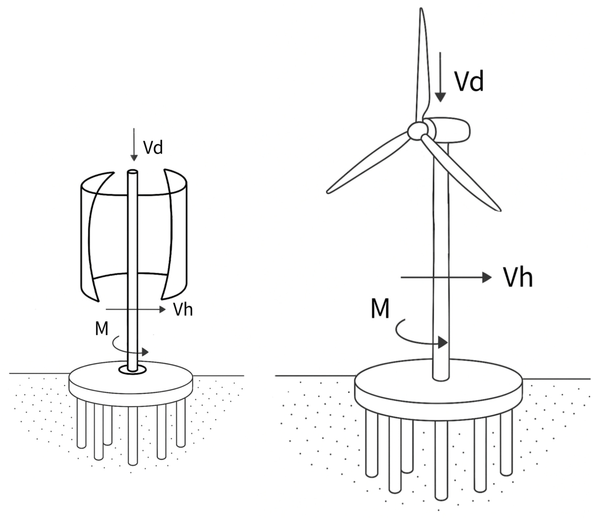
The loads acting on the analyzed example wind turbines with horizontal and vertical rotor axes were assumed in the form of vertical and horizontal forces as well as bending moments applied at the foundation level of the structure (Figure 2). The vertical force resulting from self-weight was calculated as the sum of the rotor and tower (or rotor and mast) masses multiplied by gravitational acceleration. The horizontal force was defined as the wind load corresponding to the central zone of Poland. According to the PN-EN 1991-1-4 standard [37], the basic wind speed for Zone 1 in central Poland is 22 m/s. The horizontal wind force was calculated using the following formula:
F h = 0.5 · ρ a · A · C v · v b 2
where ρa—air density, assumed as ρa = 1.225 kg/m3;
A—frontal area (for horizontal-axis turbines, the rotor area; for vertical-axis turbines, the product of height and width), m2;
Cv—aerodynamic drag coefficient (Cv = 1.2 for horizontal-axis turbines, Cv = 1.4 for vertical-axis turbines)
vb—basic wind speed, assumed as vb = 22 m/s.
Figure 2. Load schemes acting on the foundations of wind turbines with vertical and horizontal rotor axes (Vd—vertical load, Vh—horizontal force, M—bending moment).
Buildings 15 03752 g002
The bending moment was calculated based on the assumed dimensions of the tower (for horizontal-axis turbines) or mast (for vertical-axis turbines). All calculated values were rounded and are theoretical in nature, derived from average technical data of wind turbines publicly available on websites (e.g., horizontal-axis turbines: Vestas parameters [38], vertical-axis turbines: RMS turbines [39]). These values should be treated as indicative only. Each wind turbine load case should be analyzed under the specific conditions of its intended operation.
The calculations included three horizontal-axis wind turbines with rated powers of 850 kW, 1000 kW, and 2000 kW, and three vertical-axis wind turbines with significantly lower rated powers of 1 kW, 5 kW, and 10 kW. The vertical and horizontal forces, as well as bending moments at the foundation level, used for bearing capacity and settlement calculations in GEO5, are presented in Table 2.
The vertical bearing capacity of pile foundations can be determined using various methods. In this study, calculations were performed using soil parameters based on the Mohr-Coulomb hypothesis (internal friction angle, cohesion) and deformation parameters, applying the elastic method in the Pile Group module. The horizontal bearing capacity of pile foundations enabled the determination of horizontal pile displacements and internal force diagrams along the pile shaft. The actual bearing capacity of a pile was directly linked to its settlement—it can be stated that each pile undergoes vertical deformation under applied load.
The analyzed case concerns the reinforcement of weak subsoil beneath a circular wind turbine foundation, with diameters ranging from 4 m to 6 m depending on the magnitude of loads generated by the turbine. The foundation is supported by columns with diameters between 0.6 m and 1.2 m, arranged symmetrically beneath the foundation slab. Figure 3 and Figure 4 illustrate the layout of piles beneath the foundations of VAWT1 and HAWT2000 turbines. Each foundation has a circular shape, with piles evenly distributed along the circumference. The piles have identical diameters and lengths in each turbine case. The subsoil is highly stratified and characterized by low bearing capacity and high compressibility. The numerical model developed in GEO5 incorporates the geotechnical parameters of the subsoil and the material properties of the columns, including both conventional concrete and recycled concrete aggregate (RCA).
The applied loads reflect typical forces acting on wind turbine foundations, including vertical and horizontal forces as well as bending moments. The model compares the behavior of the foundation under four material variants:
  • Recycled aggregate (fRCA) with fine fraction (FF) contents of 0% (M1_0%FF);
  • Recycled aggregate (fRCA) with fine fraction (FF) contents of 30% (M4_30%FF);
  • Concrete containing recycled aggregate;
  • Conventional concrete of class C25/30.
The material properties used for the numerical calculations are presented in Table 3.
Key parameters for the models included the following:
  • Column stiffness, compressibility, and strength (from laboratory testing and literature);
  • Foundation load cases reflecting typical turbine operating conditions;
  • Settlement, stress distribution, tensile force, and bending moment in columns as output values.

3.2. Subsoil Data

The subsoil data used in this study were obtained from geotechnical investigations conducted within the city of Warsaw [39]. According to the physico-geographical regionalization of Poland, the analyzed area is located within the Warsaw Plain, where the subsurface is primarily composed of fluvial sands and gravels originating from glacial periods. Additionally, the presence of clays, silts, and loams has been identified in the subsoil [39]. The Warsaw Plain is characterized by two principal aquifer systems—Tertiary and Quaternary. Within the Quaternary formations, the groundwater table is confined and stabilizes at a depth of approximately 8 m. Field and laboratory investigations identified 11 geotechnical layers down to a depth of approximately 25 m and revealed the occurrence of intensive water seepage in the majority of soil types. The geotechnical profile, along with the basic soil properties, is presented in Table 4. These properties were determined based on investigations conducted in both the field and the laboratory. Fieldwork included borehole drilling, static cone penetration testing (CPT), and dilatometer testing (DMT). Undisturbed samples (NNS) were collected from the boreholes for laboratory analysis, which involved determining the natural water content, plastic limit, and liquid limit, as well as the strength parameters obtained from triaxial tests conducted under consolidated undrained (CU) and consolidated drained (CD) conditions. Considering the identified geological structure, the predominantly plastic or soft-plastic state of the soils, and the complex and variable geotechnical conditions, the foundation of the planned structure can be classified as challenging. Consequently, the project should be assigned to Geotechnical Category II according to EN 1997: Eurocode 7—Geotechnical design. The use of deep foundations in the form of piles is therefore justified in the design process.

4. Results and Discussion

The load-bearing capacity criterion is satisfied when the vertical load-bearing capacity of the pile, denoted as Rc (including shaft resistance and base resistance), exceeds the maximum design vertical force Vd, i.e., Rc > Vd. This indicates that the designed piles possess sufficient capacity to withstand the applied loads. Table 5 presents structural data for turbine foundations with a circular shape, including the minimum number of piles with predefined diameter and length, which satisfy the bearing capacity and serviceability requirements as determined by GEO5 calculations. Alternative structural geometries may be considered. For example, in the case of VAWT10, instead of designing 10 piles with a length of 10 m, one could opt for 12 piles with a length of 8 m, maintaining the same individual pile diameter, while still fulfilling the requirements of EC7. However, from the contractor’s perspective, it is generally more efficient to install fewer piles with greater length or diameter, rather than increasing the number of piles at the expense of their length or diameter, due to the increased frequency of equipment repositioning.
Table 6, Table 7, Table 8 and Table 9 present the results of bearing capacity and settlement analyses for four different soil materials, obtained for selected turbine foundation configurations listed in Table 5. The bearing capacity results section includes the presentation of maximum compressive and tensile forces, maximum bending moments, and shear forces values, while the serviceability analysis section provides maximum settlement, maximum horizontal displacement, and maximum slab rotation data. These values vary depending on the foundation dimensions, number of piles, and material type, with higher forces and moments observed under greater loads, regardless of the material used. The maximum settlement and horizontal displacement of the slab are relatively small (measured in millimeters), as is the slab rotation (measured in degrees).
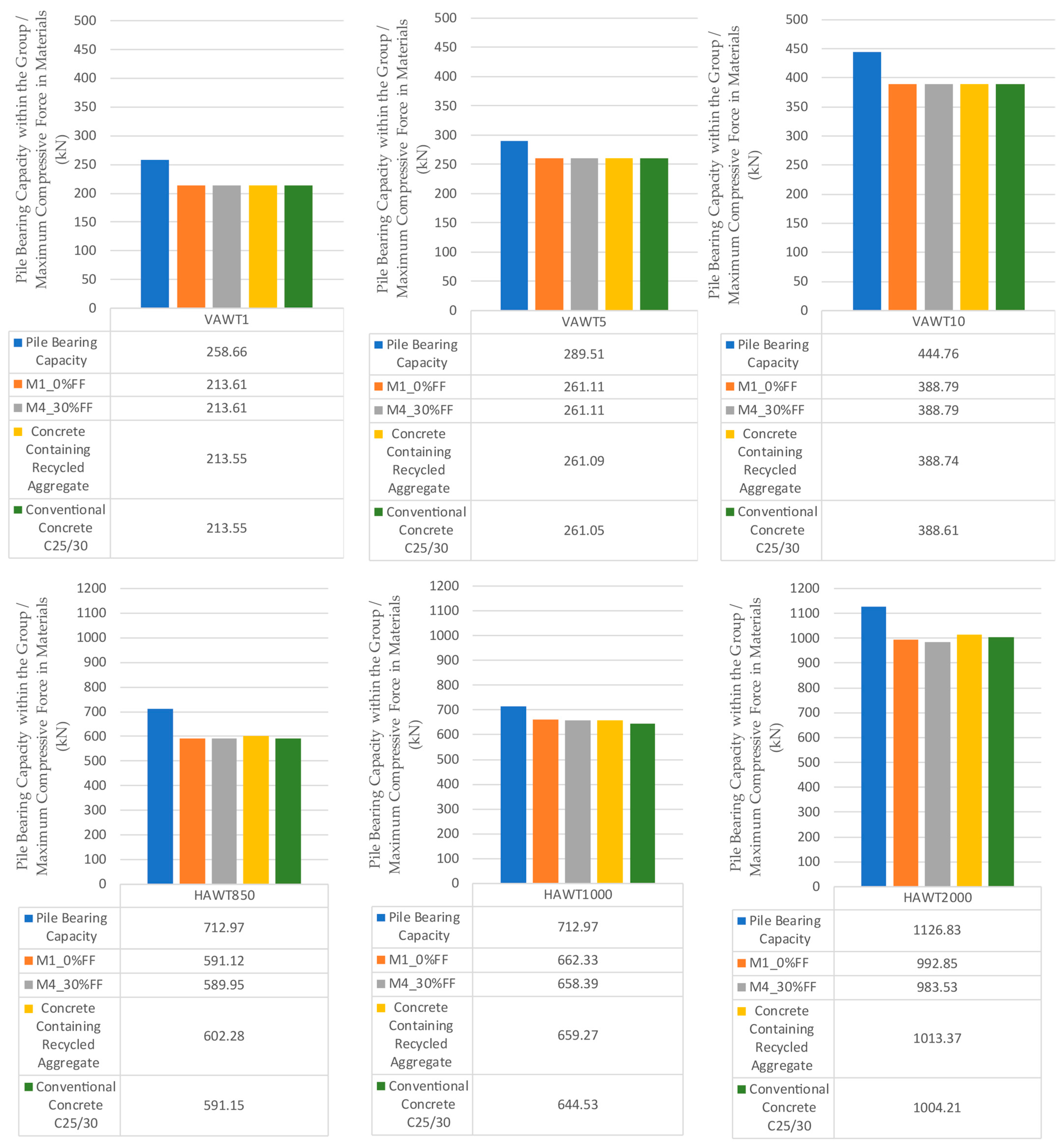
In Table 6, the results of load-bearing capacity and settlement calculations for piles made of recycled aggregate with 0% fine fraction content (M1_0%FF) are presented. The highest load values, namely maximum compressive force, maximum tensile force, maximum bending moment, and maximum shear force, were obtained for the turbine with the largest capacity, HAWT2000. Consequently, the greatest foundation deformations were observed, i.e., maximum settlement, maximum horizontal displacement, and maximum slab rotation. The pile bearing capacity within the group for the highest-capacity turbine HAWT2000 amounts to 1126.83 kN in relation to the maximum vertical force of 992.85 kN, while for the lowest-capacity turbine VAWT1 it amounts to 289.51 kN in relation to the maximum vertical force of 213.61 kN, which provides satisfactory compliance with the bearing capacity criterion.
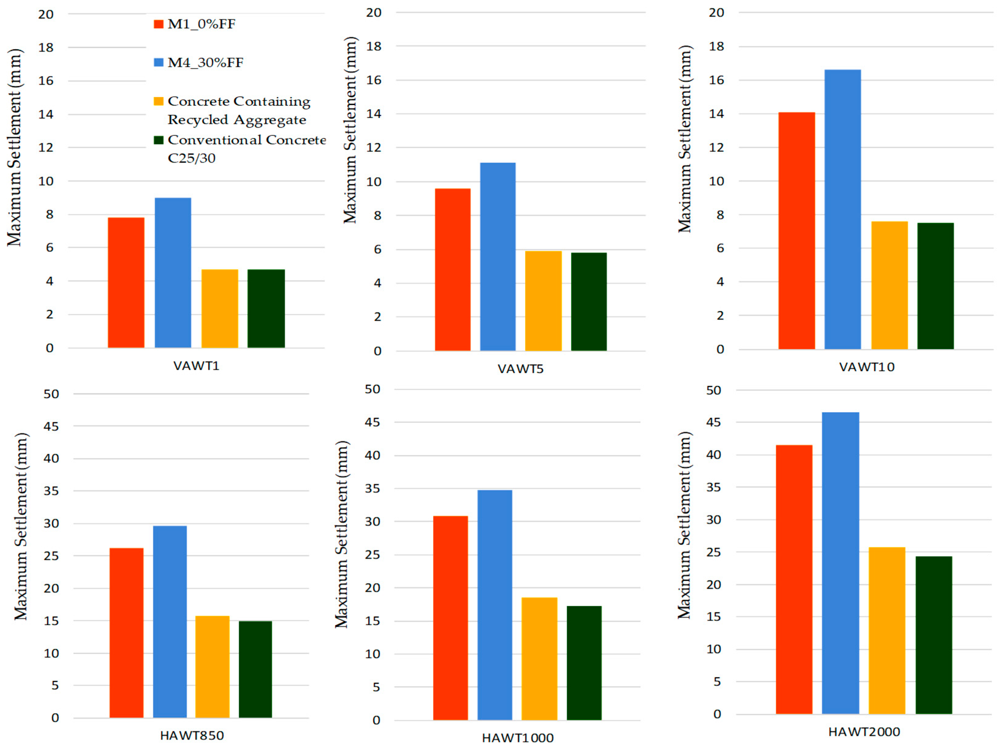
In Table 7, the results of load-bearing capacity and settlement calculations for piles made of recycled aggregate with 30% fine fraction content (M4_30%FF) are presented. Very similar results were obtained for the material with 0% fine fraction content (M1_0%FF), that is, the highest load values and the pile bearing capacity within the group were achieved for the highest-capacity turbine HAWT2000, and the lowest for the lowest-capacity turbine VAWT1. The foundation soil deformations were slightly higher for the material with 30% fine fraction content (M4_30%FF) compared to the material with 0% fine fraction content (M1_0%FF), i.e., the maximum settlement increased from 41.5 mm to 46.6 mm for the HAWT2000 turbine and from 7.8 mm to 9.0 mm for the VAWT1 turbine; similarly, the maximum horizontal displacement increased from 5.7 mm to 6.1 mm, and the maximum slab rotation from 0.17° to 0.19° for the HAWT2000 turbine, while for the VAWT1 turbine it remained at a comparable level. It follows that the addition of fine fraction (FF) does not have a significant effect on the vertical load-bearing capacity of the foundation, but it has a greater influence on the deformability of the material under load.
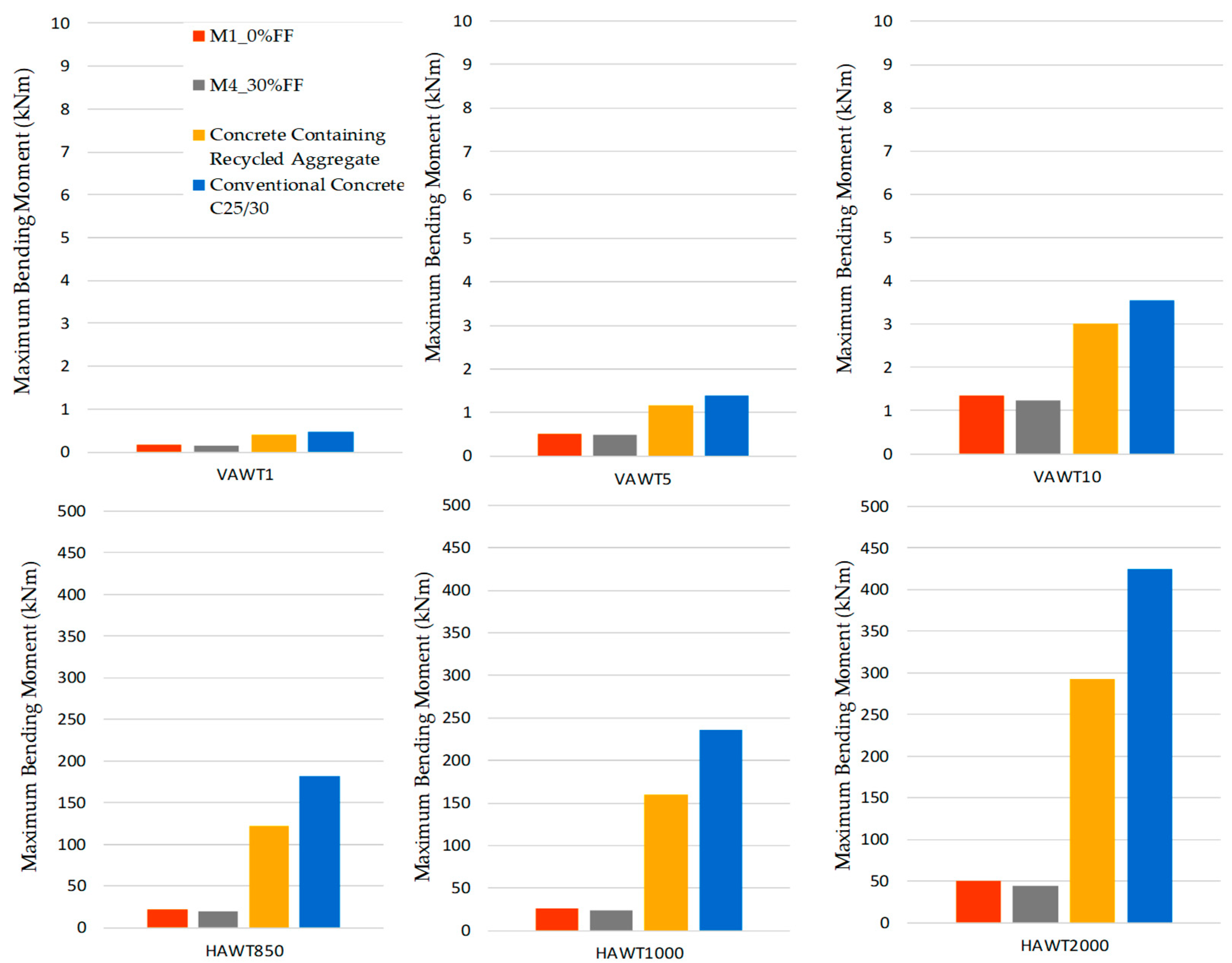
In Table 8, the results of load-bearing capacity and settlement calculations for piles made of concrete containing recycled aggregate are presented. The highest load values and the greatest foundation soil deformations were obtained for the turbine with the largest capacity, HAWT2000, and the lowest for the lowest-capacity turbine, VAWT1. In comparison with the results presented in Table 6 and Table 7, a significantly higher bending moment can be observed, which increased from 49.85 kNm for the material with 0% fine fraction content (M1_0%FF) and 44.86 kNm for the material with 30% fine fraction content (M4_30%FF) to 292.99 kNm. At the same time, the maximum settlements were considerably reduced, from 41.5 mm for the material with 0% fine fraction content (M1_0%FF) and 46.6 mm for the material with 30% fine fraction content (M4_30%FF) to 25.7 mm for the highest-capacity turbine HAWT2000. Similar trends, although with lower absolute values, were observed for the lowest-capacity turbine VAWT1, which indicates the enhanced ability of concrete to transfer torsional loads in comparison with loose aggregate.
In Table 9, the results of load-bearing capacity and settlement calculations for piles made of conventional concrete C25/30 are presented. As expected, the calculations confirmed the highest strength of this material compared to those previously presented in Table 6, Table 7 and Table 8. The table shows the greatest capacity for transferring vertical, horizontal, and torsional loads, expressed as the lowest settlement and displacement values. Apart from the maximum torsional moment, which increased from 49.85 kNm for the material with 0% fine fraction content (M1_0%FF), 44.86 kNm for the material with 30% fine fraction content (M4_30%FF), and 292.99 kNm for concrete containing recycled aggregate to 424.58 kNm for the highest-capacity turbine HAWT2000, the differences are not particularly significant, especially between the results for conventional concrete C25/30 and concrete containing recycled aggregate.
When comparing the values of maximum vertical forces acting on the most heavily loaded pile within the group, it can be observed that these values differ only slightly (Figure 5), which indicates a comparable capacity for transferring compressive (vertical) loads in both aggregates and concretes. Considering the load-bearing capacity criterion Rc/Vd, it can be observed that similar values were obtained for the individual turbines, regardless of the material type. The safest foundation in terms of vertical load was achieved for turbine VAWT1 (1.21–1.36), while the least safe was for turbine HAWT1000 (1.08–1.11), which depends on the adopted foundation diameter, number of piles, as well as pile diameter and length.
The behavior differs in the case of horizontal forces and bending moments. Figure 6 illustrates the maximum bending moment (associated with the horizontal force generated by wind) for four different materials. A clear distinction is observed between the moment values for turbines with vertical and horizontal rotor axes, which results from the geometry of the structure itself (tower height, turbine weight). For turbines with a vertical axis of rotation, the values do not exceed 4 kNm, whereas for turbines with a horizontal axis, the values are significantly higher, reaching nearly 450 kNm. Furthermore, in aggregates M1 and M4, the bending moments remain relatively low (up to 50 kNm), while in concrete materials, a substantial increase is evident. The highest capacity for transferring such loads is observed in conventional C25/30 concrete (the maximum value in the analyzed structures exceeds 400 kNm for the HAWT2000 turbine—see Figure 6). The results indicate the necessity of considering recycled aggregates as a standalone material for subgrade reinforcement beneath turbine foundations, particularly for turbines subjected to high bending moments.
The values of foundation displacements are related to the magnitude and direction of their loads, as shown in Table 6, Table 7, Table 8 and Table 9 and in Figure 7. Figure 7 presents the settlements beneath the turbines for the four tested materials. For both small turbines with a vertical axis of rotation (VAWT1, VAWT5, and VAWT10) and large turbines with a horizontal axis of rotation (HAWT850, HAWT1000, and HAWT2000), the highest values were obtained for aggregate containing 30% fine fraction (M4_30%FF), while the lowest values were observed for conventional concrete C25/30. As expected, the maximum predicted settlements for concrete are significantly smaller than those for aggregate. The difference between them is approximately twofold. For example, the settlement for the VAWT10 turbine is 7.5 mm for conventional concrete and 16.6 mm for aggregate M4_30%FF. For the HAWT2000 turbine, the corresponding values are 24.3 mm and 46.6 mm, respectively. The differences between the M1_0%FF and M4_30%FF aggregates are less pronounced. However, well-graded aggregates are more advantageous from this perspective, since the addition of fine fractions increases subsoil settlement (the FF particles fill the voids between the coarser grains under load). Nevertheless, the settlements for aggregates M1_0%FF and M4_30%FF under small turbines (and loads) are acceptable for all tested materials. However, turbines with a horizontal axis of rotation are relatively large and unfavorable from an engineering standpoint. In contrast, the differences in settlements between concrete containing recycled aggregate and conventional concrete are very small for all turbine types.
The maximum rotation of the foundation slab is predicted for large turbines on subsoil composed of aggregate M4_30%FF, i.e., 0.21° for the HAWT1000 turbine and 0.19° for the HAWT2000 turbine. In the remaining cases, the foundation rotations are acceptable; the smallest values were obtained for conventional concrete C25/30. These results of the foundation displacement calculations (maximum settlement, maximum horizontal displacement, and maximum slab rotation) confirm the limited applicability of this type of material for subsoil improvement beneath heavily loaded foundations.
The calculation results (Table 6, Table 7, Table 8 and Table 9) show that columns constructed with recycled concrete aggregate can achieve foundation bearing capacities comparable to those of piles made from both recycled and conventional concrete, particularly under the relatively low loading conditions characteristic of vertical-axis wind turbine foundations.
Under higher vertical and horizontal loads, as well as bending moments associated with the operation of horizontal-axis wind turbines, greater variability in bearing capacity was observed. In these cases, conventional concrete consistently outperformed recycled aggregate, especially with regard to bending moment resistance.
In all scenarios, vertical settlements, horizontal displacements, and slab rotations remained within acceptable limits, while the stress distribution in the subsoil confirmed effective load transfer. Slightly higher settlements and deformations were recorded for recycled aggregate and recycled concrete, which is consistent with the lower modulus of elasticity of these materials.
The fine fraction content in the recycled aggregates used—specifically in samples with 0% and 30% content of particles smaller than 2 mm—did not have a significant impact on the foundation bearing capacity or settlement results. The calculation results show that the difference between 0% and 30% FF leads to only modest changes in bearing capacity. This outcome is not due to modeling simplifications, but rather to the fact that the overall foundation response is governed mainly by the stiffness and strength of the composite subsoil system, which are only moderately affected by variations in fines content within the tested range. Intermediate mixtures (5%, 10%, 15%, and 20% FF) produced values that lay consistently between the 0% and 30% cases, confirming a gradual trend rather than a step change. The relative insensitivity of the system, therefore, reflects the soil–foundation interaction rather than a limitation of the modeling approach.
Conventional concrete C25/30 and recycled concrete exhibit higher stiffness and resistance to bending loads compared to aggregates. Aggregates—especially those with 0% fine fraction—show the highest values of settlement and slab rotation, indicating reduced foundation stability. Recycled concrete performs well under compressive and tensile forces, although it exhibits slightly greater settlement than conventional C25/30 concrete.
The presented results of the calculations indicate that the tested recycled aggregates, when used as standalone materials for ground improvement beneath structures subjected to complex loading conditions, may not be suitable. Similarly, due to the limited applicability of these aggregates in underwater environments, they are not considered appropriate for offshore wind power installations.
Numerous global studies provide data on CO2 emissions associated with conventional and recycled concrete, based on life cycle assessment (LCA) methodologies applied to concrete materials. These studies consistently show that the use of recycled aggregates reduces CO2 emissions compared to concrete produced with natural aggregates. Specifically. CO2 emissions for recycled concrete may be approximately 20% lower than those for conventional concrete. Furthermore, various sources [40,41,42,43,44,45,46] indicate that replacing conventional concrete with recycled aggregates can lead to CO2 emission reductions in the range of 40–60%, depending on the type of material and local processing conditions. These reductions are estimates, as they depend on multiple factors, including the specific stages of the concrete life cycle, transportation distances, and the proportions of natural aggregates, recycled aggregates, cement, and water used in the mix.
Table 10 presents the calculations of CO2 emission reduction during the construction of a wind farm, assuming it consists of 20 identical turbines with capacities and foundation types analyzed in this study. The assumption of 20 wind turbines was introduced to illustrate the potential scale of CO2 emission savings for a typical wind farm project. An analysis of existing developments shows that many wind farms with a total capacity of 30–50 MW, using common turbine units of 1.5–2.5 MW, comprise around 20 turbines. This configuration reflects the prevailing project sizes implemented across Europe in the past two decades, shaped by unit capacity availability, local grid constraints, and financing or permitting considerations. The emission reductions for subgrades reinforced with recycled concrete aggregate (RCA) and with aggregate were calculated in comparison to the CO2 emissions associated with conventional C25/30 concrete, based on literature data indicating reductions of 20% and 30%, respectively.
Moreover, the environmental benefit of using recycled aggregate solely for ground improvement is even greater. There is a clear need to explore broader applications of recycled materials in the construction sector and beyond. Environmental considerations strongly support the use of recycled materials; however. Further research is required to assess the long-term durability and performance of these materials. Numerical modeling using GEO5 proved to be a valuable tool for evaluating the effectiveness of ground improvement and enables design optimization.

5. Conclusions

The following conclusions can be drawn from the above considerations:
  • From a technical perspective (bearing capacity, ground settlement, structural behavior):
    • Concrete recycled aggregate derived from demolition waste is a viable alternative to natural aggregate concrete for soil reinforcement beneath wind turbine foundations, particularly in low to moderate load ranges.
    • Settlements with concrete recycled aggregate derived from demolition waste are up to 20% higher than conventional concrete but remain within acceptable limits. Reinforcement significantly improves performance.
    • Recycled concrete can be considered a fully functional engineering material, particularly in infrastructure and energy-related projects where durability and efficiency are essential.
  • In the environmental domain (CO2 emission reduction, resource efficiency):
    • The environmental benefits of concrete recycled aggregate derived from demolition waste are considerable, including reduced CO2 emissions, lower energy consumption, and diversion of waste from landfills.
    • Recycled aggregate and concrete containing recycled components support the principles of a circular economy, reduce construction waste, and limit emissions associated with transportation.
    • Their application contributes to achieving the EU’s climate objectives and promotes environmental responsibility in construction.
  • From a research perspective (material limitations, necessity of in situ testing, behavior under cyclic and dynamic loads):
    • Concrete recycled aggregate derived from demolition waste may be suitable for projects that prioritize sustainability, where ultimate stiffness is not the primary design criterion.
    • Further research should focus on the long-term performance of concrete recycled aggregate derived from demolition waste under cyclic and dynamic loading conditions, its behavior under freeze–thaw cycles, and the potential for improving its mechanical properties through biocementation.
    • There is a need for continued field studies to assess concrete recycled aggregate derived from demolition waste behavior under realistic operational scenarios and to refine design methodologies.

Author Contributions

Conceptualization, K.M.-L. and K.G.; methodology, K.M.-L.; software, M.L.; formal analysis, K.M.-L. and K.G.; investigation, K.G.; data curation, K.M.-L.; writing—original draft preparation, K.M.-L.; writing—review and editing, K.G.; visualization, K.M.-L. and K.G.; supervision, M.L. All authors have read and agreed to the published version of the manuscript.

Funding

This research received no external funding.

Data Availability Statement

The original contributions presented in the study are included in the article; further inquiries can be directed to the corresponding author.

Conflicts of Interest

The authors declare no conflicts of interest.

References

  1. Pikoń, K.; Bogacka, M.; Landrat, M.; Piecha-Sobota, K. A Guide to Circularity in Construction. Available online: https://circon.plgbc.org.pl/ (accessed on 31 August 2025).
  2. Soto-Paz, J.; Arroyo, O.; Torres-Guevara, L.E.; Parra-Orobio, B.A.; Casallas-Ojeda, M. The circular economy in the construction and demolition waste management: A comparative analysis in emerging and developed countries. J. Build. Eng. 2023, 78, 107724. [Google Scholar] [CrossRef]
  3. Eurostat. Waste Statistics. Available online: https://ec.europa.eu/eurostat/statistics-explained/index.php?title=Waste_statistics#Total_waste_generation (accessed on 31 August 2025).
  4. Statista Construction Waste as a Share of All Waste Generated in the E.U. Available online: https://www.statista.com/statistics/1399099/construction-waste-as-a-share-of-all-wastegenerated-in-the-eu/ (accessed on 31 August 2025).
  5. Fronczyk, J.; Markowska-Lech, K. Solid Waste and Recycling. In Lecture Notes in Civil Engineering; Koda, E., Vaverková, M.D., Reddy, K.R., Agnihotri, A.K., Eds.; Springer: Singapore, 2025; Volume 119, pp. 119–130. ISBN 9789819619443. [Google Scholar] [CrossRef]
  6. Ustawa z Dnia 14 Grudnia 2012 R o Odpadach (Dz, U. z 2023 R. Poz. 1587. z Późn. Zm.). Available online: https://isap.sejm.gov.pl/isap.nsf/DocDetails.xsp?id=wdu20130000021 (accessed on 31 August 2025).
  7. Rytlewska, M.; Bukowski, H.; Niedziółka, K. Report: Recovery of Building Materials—Opportunities and Challenges. Available online: www.saint-gobain.pl/raport-saint-gobain-odzysk-materialow-budowlanych (accessed on 31 August 2025).
  8. Al-Hamrani, A.; Kucukvar, M.; Alnahhal, W.; Mahdi, E.; Onat, N.C. Green Concrete for a Circular Economy: A Review on Sustainability. Durability and Structural Properties. Materials 2021, 14, 351. [Google Scholar] [CrossRef]
  9. Pacheco, J.; de Brito, J.; Lamperti Tornaghi, M. Use of Recycled Aggregates in Concrete: Opportunities for Upscaling in Europe; Publications Office of the European Union: Luxembourg, 2023. [Google Scholar] [CrossRef]
  10. Knoeri, C.; Sanyé-Mengual, E.; Althaus, H.-J. Comparative LCA of recycled and conventional concrete for structural applications. Int. J. Life Cycle Assess. 2013, 18, 909–918. [Google Scholar] [CrossRef]
  11. Turk, J.; Cotič, Z.; Mladenovič, A.; Šajna, A. Environmental evaluation of green concrete versus conventional concrete by means of LCA. J. Clean. Prod. 2015, 87, 613–619. [Google Scholar] [CrossRef] [PubMed]
  12. Almusaed, A.; Yitmen, I.; Myhren, J.A.; Almssad, A. Assessing the Impact of Recycled Building Materials on Environmental Sustainability and Energy Efficiency: A Comprehensive Framework for Reducing Greenhouse Gas Emissions. Buildings 2024, 14, 1566. [Google Scholar] [CrossRef]
  13. Kumar, B.N.; Vineela, P.S.; Bhat, D.K. Revolutionizing concrete through sustainable Practices: A performance study on strength variation under acidic environments. Discov. Sustain. 2025, 6, 418. [Google Scholar] [CrossRef]
  14. Chamasemani, N.F.; Kelishadi, M.; Mostafaei, H.; Najvani, M.A.D.; Mashayekhi, M. Environmental Impacts of Reinforced Concrete Buildings: Comparing Common and Sustainable Materials: A Case Study. Constr. Mater. 2024, 4, 1–15. [Google Scholar] [CrossRef]
  15. Attri, G.; Gupta, R.C.; Shrivastava, S. Comparative Environmental Impacts of Recycled Concrete Aggregate and Manufactured Sand Production. Process Integr. Optim. Sustain. 2022, 6, 737–749. [Google Scholar] [CrossRef]
  16. Luo, J.; Huang, R.; Wang, J.; Zhang, Y. Carbon Sequestration by Preparing Recycled Cement. Recycled Aggregates. and Recycled Concrete from Construction and Demolition (C&D) Wastes. Materials 2024, 17, 5020. [Google Scholar] [CrossRef]
  17. Barbhuiya, S.; Das, B.B.; Adak, D.; Kapoor, K.; Tabish, M. Low carbon concrete: Advancements. challenges and future directions in sustainable construction. Discov. Concr. Cem. 2025, 1, 3. [Google Scholar] [CrossRef]
  18. Singh, S.; Singh, S.K.; Mahgoub, M.; Mir, S.A.; Kanga, S.; Kumar, S.; Kumar, P.; Meraj, G. Evaluating Recycled Concrete Aggregate and Sand for Sustainable Construction Performance and Environmental Benefits. CivilEng 2024, 5, 461–481. [Google Scholar] [CrossRef]
  19. Badiger, M.; Mamatha, K.H.; Dinesh, S.V. Mechanical Evaluation of Granular Sub-base Reinforced with Recycled Tyres: A Way Towards Sustainability. Geotech. Geol. Eng. 2025, 43, 189. [Google Scholar] [CrossRef]
  20. Prasittisopin, L.; Tuvayanond, W.; Kang, T.H.-K.; Kaewunruen, S. Concrete Mix Design of Recycled Concrete Aggregate (RCA): Analysis of Review Papers. Characteristics. Research Trends. and Underexplored Topics. Resources 2025, 14, 21. [Google Scholar] [CrossRef]
  21. Arulrajah, A.; Piratheepan, J.; Disfani, M.M.; Bo, W. Geotechnical and Geoenvironmental Properties of Recycled Construction and Demolition Materials in Pavement Subbase Applications. J. Mater. Civ. Eng. 2013, 25, 1077–1088. [Google Scholar] [CrossRef]
  22. Vieira, C.S.; Pereira, P.M. Use of recycled construction and demolition materials in geotechnical applications: A review. Resour. Conserv. Recycl. 2015, 103, 192–204. [Google Scholar] [CrossRef]
  23. Han, S.; Zhao, S.; Lu, D.; Wang, D. Performance Improvement of Recycled Concrete Aggregates and Their Potential Applications in Infrastructure: A Review. Buildings 2023, 13, 1411. [Google Scholar] [CrossRef]
  24. Shah, S.K.H.; Uchimura, T.; Kawamoto, K. Permanent Deformation and Breakage Response of Recycled Concrete Aggregates under Cyclic Loading Subject to Moisture Change. Sustainability 2022, 14, 5427. [Google Scholar] [CrossRef]
  25. Santos, C.N.; Cetin, B. Saturated and unsaturated properties of recycled concrete aggregate for sustainable pavement design. Transp. Geotech. 2025, 52, 101578. [Google Scholar] [CrossRef]
  26. Alibeigibeni, A.; Stochino, F.; Zucca, M.; Gayarre, F.L. Enhancing Concrete Sustainability: A Critical Review of the Performance of Recycled Concrete Aggregates (RCAs) in Structural Concrete. Buildings 2025, 15, 1361. [Google Scholar] [CrossRef]
  27. Gabryś, K. Shear modulus and damping ratio of recycled concrete aggregate from cyclic torsional shear test. Roads Bridges 2023, 22, 387–398. [Google Scholar] [CrossRef]
  28. Gabryś, K.; Šadzeviĉius, R.; Dapkienė, M.; Ramukeviĉius, D.; Sas, W. Effect of a Fine Fraction on Dynamic Properties of Recycled Concrete Aggregate as a Special Anthropogenic Soil. Materials 2023, 16, 4986. [Google Scholar] [CrossRef]
  29. Gabryś, K.; Markowska-Lech, K.; Sas, W. Small-strain stiffness of selected anthropogenic aggregates from bender element tests. Stud. Geotech. Mech. 2024, 46, 193–206. [Google Scholar] [CrossRef]
  30. Arola, A. Use Recycled Concrete Aggregate in Concrete Manufacturing. Master’s Thesis, Aalto University, Espoo, Finland, 2022. Available online: https://aaltodoc.aalto.fi/server/api/core/bitstreams/5571d9b6-e937-4c9c-b8e3-4accb3b24a18/content (accessed on 31 August 2025).
  31. Klabacha, A. Zastosowanie Cementów z Dodatkiem Popiołu Lotnego do Produkcji Betonów Posadzkowych, Holcim Polska S.A. Available online: https://www.holcim.pl/blog/zastosowanie-cementow-z-dodatkiem-popiolu-lotnego-v-do-produkcji-betonow-posadzkowych (accessed on 31 August 2025).
  32. PN-EN ISO 14688-2:2018-05; Geotechnical Investigation and Testing—Identification and Classification of Soil—Part 2: Principles for a Classification (ISO 14688-2:2017). Polish Committee for Standardization: Warsaw, Poland, 2018.
  33. Geotechnical Software GEO5, ver. 2025.61 Educational Version; Fine Software: Prague, Czech Republic, 2025; Available online: https://www.finesoftware.eu/geotechnical-software/ (accessed on 31 August 2025).
  34. GEO5: Analysis of Vertical Load Bearing Capacity and Settlement of a Pile Group; Fine Software: Prague, Czech Republic; Available online: https://www.finesoftware.eu/geo5/pile-group/ (accessed on 31 August 2025).
  35. GEO5: Analysis of Deformation and Pile Group Dimensioning; Fine Software: Prague, Czech Republic; Available online: https://www.finesoftware.eu/geo5/pile-group/ (accessed on 31 August 2025).
  36. EN 1997; Eurocode 7—Geotechnical Design, European Standard. European Committee for Standardization: Brussels, Belgium, 2007.
  37. Dlubal Software. Wind Load Zones According to PN-EN 1991-1-4. Available online: https://www.dlubal.com/pl/strefy-obciazenia-sniegiem-wiatrem-trzesieniem-ziemi/wiatr-pn-en-1991-1-4.html#&center=52.01193653675363.19.138183593750004&marker=52.231782.21.021438 (accessed on 31 August 2025).
  38. Elektrownie Vestas—Parametry. Elektroonline.pl. Available online: http://elektroonline.pl/a/1339.Elektrownie-Vestas-parametry (accessed on 31 August 2025).
  39. Turbiny Wiatrowe o Pionowej Osi Obrotu. Available online: https://www.rms.com.pl/oferta/turbiny-i-silownie-wiatrowe/turbiny-wiatrowe-o-pionowej-osi-obrotu/ (accessed on 31 August 2025).
  40. Cavalieri, F.; Bellotti, D.; Caruso, M.; Nascimbene, R. Comparative evaluation of seismic performance and environmental impact of traditional and dissipation-based retrofitting solutions for precast structures. J. Build. Eng. 2023, 79, 107918. [Google Scholar] [CrossRef]
  41. Jiménez, L.F.; Domínguez, J.A.; Vega-Azamar, R.E. Carbon Footprint of Recycled Aggregate Concrete. Adv. Civ. Eng. 2018, 2018, 7949741. [Google Scholar] [CrossRef]
  42. Zhang, J.; Huang, Z.; Zhu, Z.; Yang, S.; Wei, J. Research progress of the recycled aggregate concrete in life cycle assessment. J. Build. Des. Environ. 2024, 2, 32570. [Google Scholar] [CrossRef]
  43. Sabau, M.; Bompa, D.V.; Silva, L.F.O. Comparative carbon emission assessments of recycled and natural aggregate concrete: Environmental influence of cement content. Geosci. Front. 2021, 12, 101235. [Google Scholar] [CrossRef]
  44. Estévez, B.G.; Aguado, A.; Josa, A. Environmental Impact of Concrete Recycling. Coming from Construction and Demolition Waste (C&DW). Available online: https://www.irbnet.de/daten/iconda/CIB865.pdf (accessed on 31 August 2025).
  45. Zhu, W.; Li, J.; Wang, L.; Li, X. Sustainable design of recycled concrete using shape optimization and carbon dioxide emission based on LCA. J. Civ. Eng. Manag. 2025, 31, 631–645. [Google Scholar] [CrossRef]
  46. Jeon, M.-K.; Kim, J.; Ham, S.-M.; Kim, S.; Han, A.T.; Kim, H.; Kwon, T.-H. CO2 treatment of recycled concrete aggregates with high mortar contents: From finding optimal treatment condition. quality enhancement. to life cycle assessment. Constr. Build. Mater. 2024, 447, 137953. [Google Scholar] [CrossRef]
  47. OEKOBAUDAT 2024-I. Available online: https://www.climatiq.io/data/emission-factor/7f5c9dbe-2259-4bea-8236-cefc18e83365 (accessed on 31 August 2025).
Figure 1. Grading curves of the tested fRCA samples M1–M2 [29], compared with recycled concrete aggregate (RCA) [30] and conventional concrete C25/30 [31].
Buildings 15 03752 g001
Figure 3. Schematic layout of piles beneath the foundation of VAWT1 turbine from GEO5 (pile diameter: 0.6 m, pile length: 5 m, foundation radius: 4 m, number of piles: 8).
Buildings 15 03752 g003
Figure 4. Schematic layout of piles beneath the foundation of HAWT2000 turbine from GEO5 (pile diameter: 1.0 m, pile length: 12 m, foundation radius: 8 m, number of piles: 24).
Buildings 15 03752 g004
Figure 5. Comparison of pile bearing capacity in a group under maximum vertical forces for selected turbine foundations in four different materials.
Buildings 15 03752 g005
Figure 6. Maximum bending moment values for selected turbine foundations in four different materials.
Buildings 15 03752 g006
Figure 7. Settlement values for selected turbine foundations in four different materials.
Buildings 15 03752 g007
Table 1. Physical properties of fRCA in this study.
Specimen CodeFraction
(mm)
Mean Grain Size D50
(mm)
Preparation MethodInitial Void Ratio e0Initial Dry Unit Weight γd0
(kN/m3)
M1_0%FF0.063–2.00.20Dry tamping0.6116.29
M2_10%FF0.02–1.00.16Dry tamping0.6316.08
M3_20%FF0.015–0.80.14Dry tamping0.7215.43
M4_30%FF0.015–0.60.21Dry tamping0.8114.62
M5_5%FF0.02–2.00.21Moist tamping0.7414.96
M6_15%FF0.02–1.00.18Moist tamping0.7115.00
Table 2. Load values assumed for calculations in GEO5.
Turbine/
Rotor Type
Power
(kW)
Tower/Mast Height (m)Rotor (for Horizontal) or Turbine (for Vertical) Diameter (m)Rotor Weight (t)Tower (Horizontal) or Mast (Vertical) Weight (t)Vertical Load (kN)Horizontal Force (kN)Bending Moment (kNm)
HAWT850850555210137.5150030016,500
HAWT10001000606018150.0170035021,000
HAWT20002000808023200.0220060048,000
VAWT115.51.80.1813.75140211
VAWT555.540.9513.75150740
VAWT10101161.727.5030016180
Table 3. Material data used for calculations.
Material TypeCompressive
Strength fck
(MPa)
Tensile
Strength fctm
(MPa)
Elastic
Modulus Ecm
(MPa)
Shear
Modulus G (MPa)
Recycled aggregate with 0% fine fraction content (M1_0%FF)81.2442.5177.0
Recycled aggregate with 30% fine fraction content (M4_30%FF)81.2315.5126.27
Concrete containing recycled aggregate151.515,0006250
Conventional concrete C25/30252.631,00012,917
Table 4. Geotechnical soil profile adopted for the numerical analysis GEO5.
Layer No.Layer Thickness
(m)
Soil TypeLiquidity Index LI/Relative Density DrBulk Density γ
(kN/m3)
Effective Internal Friction Angle φ′
(°)
Cohesion c′
(kPa)
Poisson’s Ratio ν
(–)
11.20saClLI = 0.2019.527.0100.35
21.20FSa/siSaDr = 0.4517.529.5-0.30
31.00grSaDr = 0.5020.035.5-0.20
41.80saClLI = 0.2018.524.5140.35
54.00SiLI = 0.3020.021.0120.40
65.90saClLI = 0.1521.019.0120.40
77.90saClLI = 0.1021.019.0120.40
Table 5. Summary of exemplary pile configurations satisfying the bearing capacity and serviceability requirements for turbine foundations, as determined by calculations performed in GEO5.
Turbine/
Rotor Type
Number
of Piles
Pile
Diameter
(m)
Pile
Length
(m)
Foundation
Radius
(m)
HAWT850200.8106
HAWT1000220.8106
HAWT2000241.0128
VAWT180.654
VAWT5100.665
VAWT10100.6106
Table 6. Results of load-bearing capacity and settlement calculations for piles made of recycled aggregate with 0% fine fraction content (M1_0%FF).
Turbine TypeVAWT
1
VAWT
5
VAWT
10
HAWT
850
HAWT
1000
HAWT
2000
Maximum Compressive Force Vd (kN)213.61261.11388.79591.12662.33992.85
Maximum Tensile Force (kN)23.7721.545.31159.48206.57312.06
Maximum Bending Moment (kNm)0.170.521.3422.0125.8449.85
Maximum Shear Force (kN)0.250.71.61515.9125
Maximum Settlement (mm)7.89.614.126.230.941.5
Maximum Horizontal Displacement (mm)00.10.43.94.65.7
Maximum Slab Rotation (°)0.000530.000820.00230.140.180.17
Pile Bearing Capacity within the Group Rc (kN)289.51289.51444.76712.97712.971126.83
Load-Bearing Capacity Criterion R c V d > 1 1.36
Satisfied
1.11
Satisfied
1.14
Satisfied
1.21
Satisfied
1.08
Satisfied
1.13
Satisfied
Table 7. Results of load-bearing capacity and settlement calculations for piles made of recycled aggregate with 30% fine fraction content (M4_30%FF).
Turbine TypeVAWT
1
VAWT
5
VAWT
10
HAWT
850
HAWT
1000
HAWT
2000
Maximum Compressive Force Vd (kN)213.61261.11388.79589.95658.39983.57
Maximum Tensile Force (kN)21.5419.4637.4160.86209.24317.57
Maximum Bending Moment (kNm)0.160.481.2419.9323.244.86
Maximum Shear Force (kN)0.250.71.61515.9125
Maximum Settlement (mm)911.116.629.634.846.6
Maximum Horizontal Displacement (mm)00.10.44.256.1
Maximum Slab Rotation (°)0.000620.000960.00270.160.210.19
Pile Bearing Capacity within the Group Rc (kN)289.51289.51444.76712.97712.971126.83
Load-Bearing Capacity Criterion R c V d > 1 1.36
Satisfied
1.11
Satisfied
1.14
Satisfied
1.21
Satisfied
1.08
Satisfied
1.14
Satisfied
Table 8. Results of load-bearing capacity and settlement calculations for piles made of concrete containing recycled aggregate.
Turbine TypeVAWT
1
VAWT
5
VAWT
10
HAWT
850
HAWT
1000
HAWT
2000
Maximum Compressive Force Vd (kN)213.55261.09388.74602.28659.271013.37
Maximum Tensile Force (kN)30.4727.878.6121.86160.93241.14
Maximum Bending Moment (kNm)0.41.163121.82159.29292.99
Maximum Shear Force (kN)0.250.71.618.8924.8737.76
Maximum Settlement (mm)4.75.97.615.718.525.7
Maximum Horizontal Displacement (mm)00.10.13.54.65.1
Maximum Slab Rotation (°)0.000290.000470.00110.0760.0990.086
Pile Bearing Capacity within the Group Rc (kN)258.66289.51444.76712.97712.971126.83
Load-Bearing Capacity Criterion R c V d > 1 1.21
Satisfied
1.11
Satisfied
1.14
Satisfied
1.18
Satisfied
1.08
Satisfied
1.11
Satisfied
Table 9. Results of load-bearing capacity and settlement calculations for piles made of conventional concrete C25/30.
Turbine TypeVAWT
1
VAWT
5
VAWT
10
HAWT
850
HAWT
1000
HAWT
2000
Maximum Compressive Force Vd (kN)213.55261.05388.61591.15644.531004.21
Maximum Tensile Force (kN)30.5927.9279.41103.54140.45213.15
Maximum Bending Moment (kNm)0.471.383.55181.72235.48424.58
Maximum Shear Force (kN)0.250.71.627.7336.1854.5
Maximum Settlement (mm)4.75.87.514.917.324.3
Maximum Horizontal Displacement (mm)000.13.84.95.5
Maximum Slab Rotation (°)0.000280.000460.00110.0680.0880.076
Pile Bearing Capacity within the Group Rc (kN)258.66289.51444.76712.97712.971126.83
Load-Bearing Capacity Criterion R c V d > 1 1.21
Satisfied
1.11
Satisfied
1.14
Satisfied
1.21
Satisfied
1.11
Satisfied
1.12
Satisfied
Table 10. Calculated CO2 emission reductions for subgrade reinforcement solutions.
Turbine/
Rotor Type
Concrete Volume per Single Structure
(m3)
CO2 Emissions for Single Structure of C25/30 Concrete *
(kg CO2)
CO2 Emissions for Wind Farm Foundations
(kg CO2)
CO2 Emission Reduction for RCA
(kg CO2)
CO2 Emission Reduction for Aggregate
(kg CO2)
HAWT850128.811148.0422,960.834592.176888.25
HAWT1000138.861237.6424,752.904950.587425.87
HAWT2000216.771932.0738,641.407728.2811,592.42
VAWT123.88212.814256.15851.231276.85
VAWT536.60326.216524.241304.851957.27
VAWT1056.55504.0210,080.372016.073024.11
* The mean carbon dioxide emission associated with C25/30 concrete is 8.913 kg CO2/m3 [47].
Disclaimer/Publisher’s Note: The statements, opinions and data contained in all publications are solely those of the individual author(s) and contributor(s) and not of MDPI and/or the editor(s). MDPI and/or the editor(s) disclaim responsibility for any injury to people or property resulting from any ideas, methods, instructions or products referred to in the content.