Article

A Macro-Scale Modeling Approach for Capturing Bending-Shear Coupled Dynamic Behavior in High-Rise Structures Using Deep Learning

1
School of Intelligent Civil and Ocean Engineering, Harbin Institute of Technology, Shenzhen 518055, China
2
Department of Civil & Environmental Engineering, Syracuse University, Syracuse, NY 13244-1240, USA
*
Author to whom correspondence should be addressed.
Buildings 2025, 15(20), 3727; https://doi.org/10.3390/buildings15203727
Submission received: 15 September 2025 / Revised: 9 October 2025 / Accepted: 14 October 2025 / Published: 16 October 2025

Abstract

Macro-scale modeling is a fundamental approach for assessing structural damage and occupant comfort in urban high-rises during earthquakes or typhoons. The key to its effectiveness is accurately reproducing dynamic responses and extracting modal characteristics. The critical issue is whether the macro-scale model can effectively capture Flexure-Shear Coupled (FSC) dynamic behavior. This paper proposes a macro-scale modeling method for high-rise structures with FSC dynamic behavior using deep learning (DL). FSC dynamic behavior is quantified by establishing Displacement Interaction Coefficients (DInC) under each mode shape. To account for the flexural resistance of horizontal members and the anti-overturning contribution of vertical members in high-rise structures, equivalent stiffness parameters representing horizontal and vertical members are introduced into the Lumped Parameter Model (LPM), enhancing the flexibility of the macro-scale model in expressing FSC dynamic behavior. The DInCs are used as input features to identify the LPM’s stiffness parameters, enabling efficient macro-scale modeling. The method was validated on a frame and a frame-core tube structure by comparing dynamic characteristics with their detailed finite element models. This method holds engineering application potential in areas requiring highly accurate and rapid structural characteristic or response calculations, such as seismic response analysis and design optimization of high-rise structures.

1. Introduction

Under extreme hazards such as earthquakes and typhoons, high-rise structures often encounter a series of complex serviceability issues, including structural damage, non-structural component failures, and abnormal vibrations [1,2]. Efficient computation of structural responses for urban high-rise building clusters under natural disasters is crucial for rapid serviceability performance assessment [3,4]. Macro-scale modeling, widely adopted for high-rise structural serviceability assessment due to its computational efficiency and convenient parameter/data processing capabilities, primarily utilizes three model types: Shear Models (SM), Beam-element Models (BM), and Lumped Parameter Models (LPM). SM can effectively capture the first two vibration frequencies and mode shapes of actual structures [5,6,7,8] but fails to represent flexural deformations. However, as one of the primary deformation modes of high-rise structures under dynamic loads [9,10], flexural deformation plays a decisive role in their overall dynamic response.
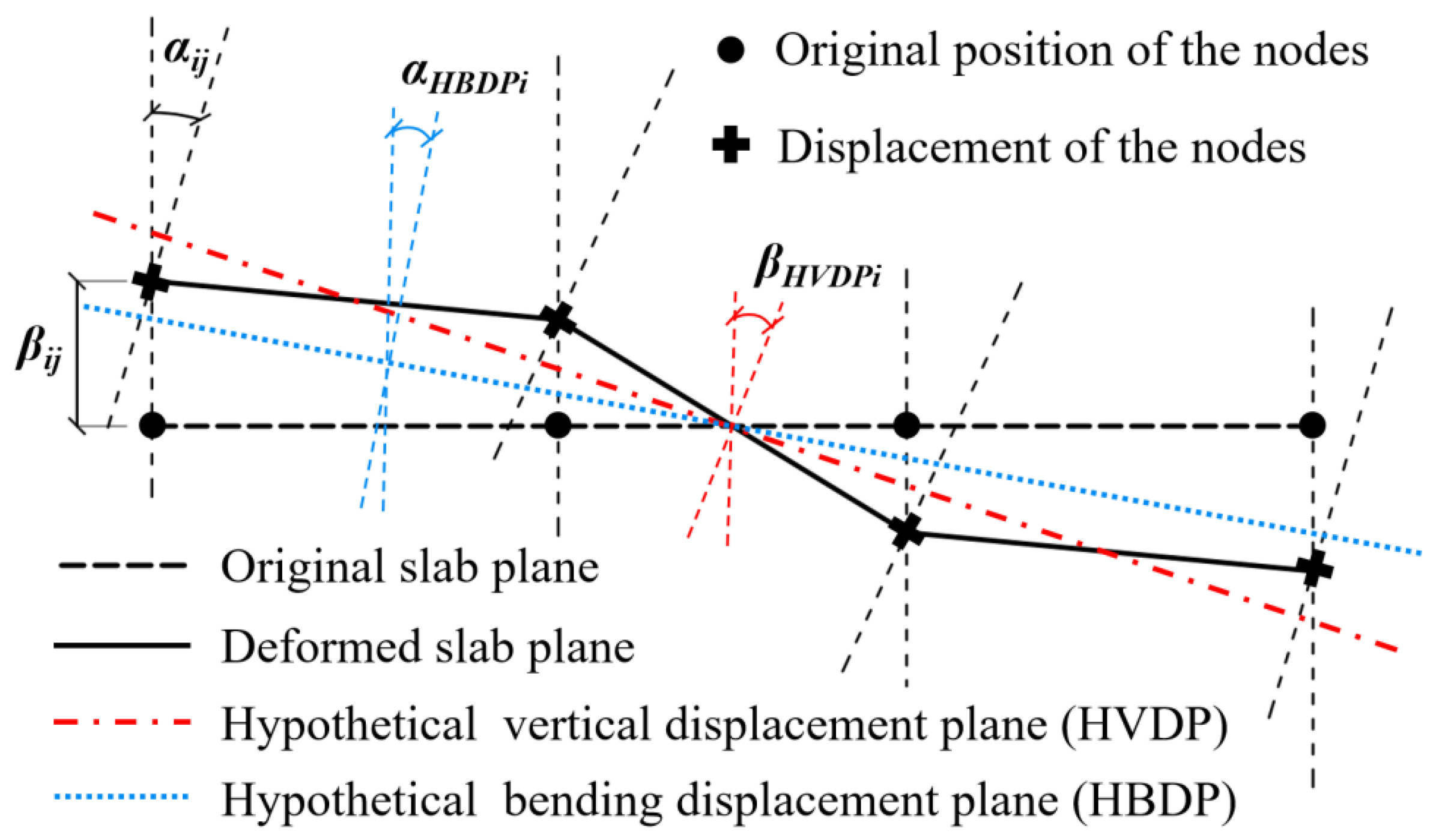
The BM, typically employing serial-connected Timoshenko beams for macro-scale modeling, enhances the flexibility in simulating flexure displacement, thereby providing an effective modeling framework for digitally replicating the complex behavior of high-rise structures [11,12,13,14]. However, the BM essentially assumes the horizontal members as rigid bodies while computing equivalent stiffness parameters of all vertical members as beam elements. As illustrated in Figure 1, when horizontal members are hypothetically rigid, the substructure of a high-rise building’s floor will only exhibit horizontal shear deformation and rotational deformation induced by tension-compression of vertical members under lateral loads. In reality, however, horizontal members develop resisting moments (Mij) and shear forces (Fij) when subjected to joint torsional deformations, which subsequently influence floor rotations and tilt angles, thereby significantly complicating the Flexure-Shear Coupled (FSC) dynamic behavior. This mechanism is explicitly illustrated by the jth horizontal member at the ith floor in Figure 1. Nevertheless, the FSC dynamic behavior at the floor level profoundly influences the natural vibration characteristics, modal distributions, and time-history response amplitudes in macro-scale modeling. Accurate characterization and representation of the FSC dynamic behavior represent the fundamental challenge in improving the accuracy of macro-scale structural modeling.
LPM has partially addressed this issue, as exemplified by the fishbone model’s incorporation of torsion-resistant rigid arms and restraining springs to account for horizontal members’ resistance to floor flexural deformations [15,16,17,18]. Qu et al. [16] used a fishbone model to simulate a reinforced concrete frame, studying the influence of the column-to-beam strength and stiffness ratio. The torsional spring setting accounted for the contribution of horizontal components to the structural bending capacity, which resulted in a good fit between the natural frequency. However, the increased number of constraints caused inconsistencies between the model’s predicted bending moments and the actual behavior. The internal forces at each floor level significantly influence the FSC behavior of high-rise structures. Moreover, key engineering design parameters require floor-level internal force calculations—such as overturning moments and inter-story shear ratios—serve as critical indicators for evaluating structural mechanical performance. Another critical aspect warrants attention: as illustrated in Figure 1, the FSC behavior of high-rise structures encompasses not only joint rotations at floor levels but also story inclination angles induced by vertical nodal deformations—a key factor influencing structural overturning resistance that current BM and LPM fail to consider. This necessitates developing macro-scale models capable of: (1) considering the flexural resistance of horizontal members without introducing additional constraints that would lead to discrepancies in the internal forces of the floor, and (2) considering the anti-overturning contribution of vertical members and explicitly representing story inclination mechanisms, thereby enabling more accurate modeling of the FSC dynamic behavior of the high-rise structures.
The accurate modeling of global mechanical behavior in high-rise structures requires not only a highly flexible macro-scale modeling framework but also a precise determination of model parameters, which is crucial for achieving this technical objective. Specifically, regarding the condensation of equivalent stiffness parameters, the equivalent shear stiffness and bending stiffness are generally determined using closed-form analytical formulas, whereas for complex structures, pushover analysis is required for parameter identification, with the calculation based on the relationship between force and displacement. However, these methods may yield suboptimal identification results due to their neglect of inter-story interactions and boundary condition variations or owing to errors introduced by computational simplifications. For a more flexible macro-scale model that accounts for the bending capacity of horizontal members and the anti-overturning effect of vertical members—with a greater variety and number of parameter types—the issue of parameter identification in macro-scale modeling becomes even more complex. The coupling relationships between parameters make traditional methods difficult to apply. Optimization algorithms or artificial neural networks (ANNs) provide a method for enhanced model parameter identification [13,19,20]. Shan et al. [19] proposed a parameter identification framework with a particle swarm optimization (PSO) algorithm, which was used to update the macro-scale model of shear-wall structures based on vibration data. The results showed that the optimal parameters identified were robust in terms of ground motion and sensor allocation. Gonzalez and Zapico [21] employed artificial neural networks to identify parameters of a simplified model for a five-story office building. Their approach utilized natural frequencies and mode shapes as input features, with mass and stiffness parameters as output targets, demonstrating robust performance in damage identification through simulated data validation. Nowadays, Deep learning (DL), like Convolutional Neural Network (CNN), has achieved significant advancements [22,23]. With their outstanding capabilities in processing multi-source heterogeneous data and recognizing complex patterns, they can provide new solutions for identifying parameters in macro-scale modeling. Therefore, by establishing a flexible macro-scale model that characterizes the FSC dynamic behavior of high-rise structures and integrating emerging DL-driven research advancements, a parameter identification framework for macro-scale modeling can be developed. This enables the structural “skeleton” (flexible macro-scale model) to be endowed with precise “muscles” (parameter identification), thereby digitally reproducing the global dynamic characteristics of real-world buildings or detailed finite element models (FEM).
This paper proposes a macro-scale modeling method with FSC dynamic behavior in high-rise structures using DL, specifically CNN. The process mainly consists of three steps, as illustrated in Figure 2: (1) By establishing Displacement Interaction Coefficients (DInC) under each mode shape, the coupling effects of horizontal, vertical, and bending displacements at different floors are quantified to describe the FSC dynamic behavior in high-rise structures. (2) To account for both the flexural resistance of horizontal members and the anti-overturning capacity of vertical members in high-rise structures, equivalent stiffness parameters representing these components are incorporated into the LPM. This modification improves the flexibility of the macro-scale model in capturing the FSC dynamic behavior. (3) DInCs are integrated as input features for CNN to identify the equivalent stiffness parameters of the enhanced LPM, thereby achieving the macro-scale modeling of the FSC dynamic behavior in high-rise structures. The macro-scale models thus obtained can more accurately reflect the dynamic characteristics of the high-rise structure and possess higher flexibility which holds engineering application potential in areas requiring highly accurate and rapid structural characteristic or response calculations, such as seismic response analysis and design optimization of high-rise structures. By combining the monitoring and identification of the overall dynamic characteristics of real high-rise structures and the acquisition of floor responses under the action of earthquakes or typhoons, this model provides a theoretical model foundation for achieving accurate and rapid macro-scale digital twins of real high-rise structures.

2. FSC Behavior Parameterization and Modeling Method

2.1. Displacement Interaction Coefficients

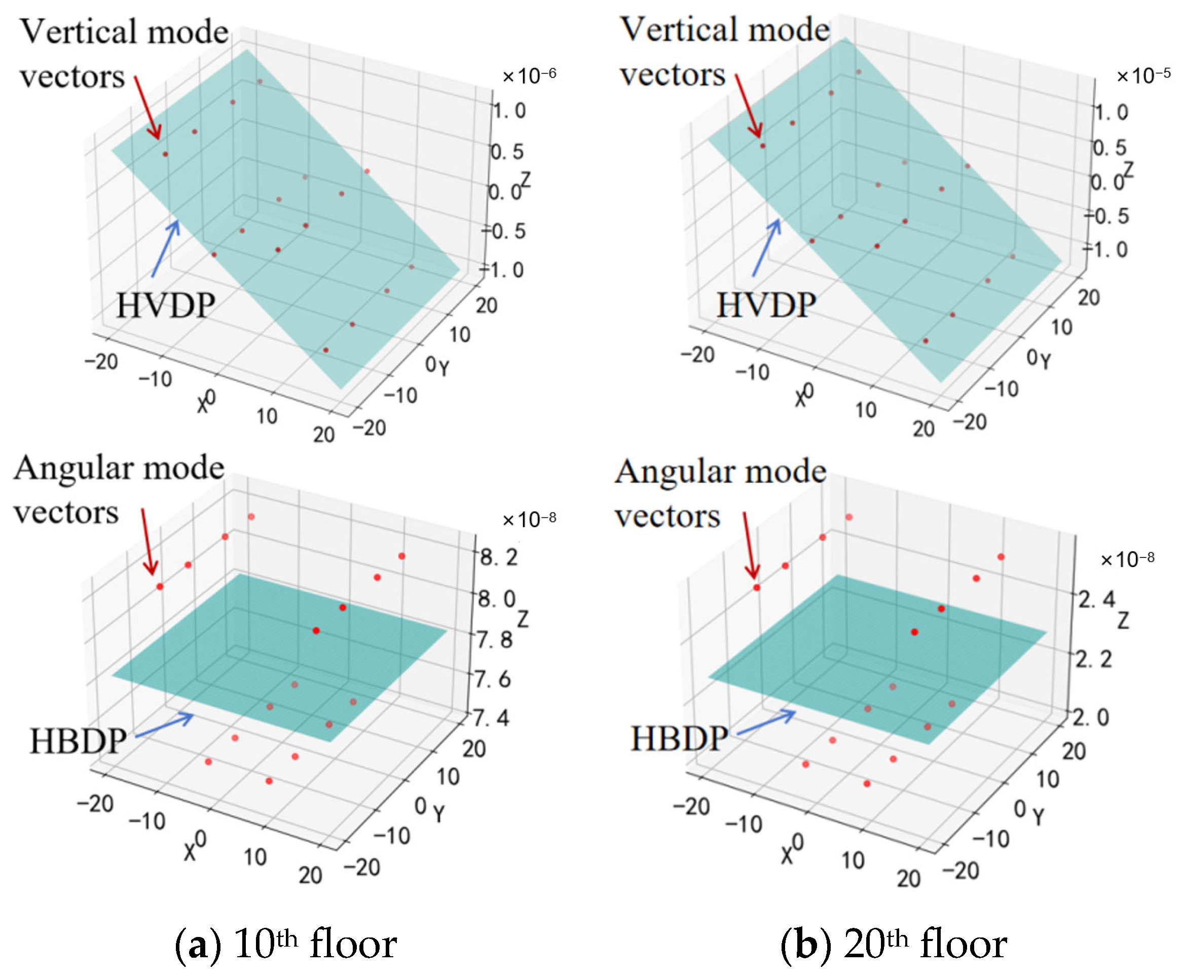
High-rise structures usually adopt the rigid floor diaphragm assumption. The total lateral displacement ΔTi of the ith floor is represented by the displacements at the coupling points of the slab. However, the rigid floor diaphragm assumption does not constrain the vertical deformation and torsional rotation of the nodes. To quantitatively represent the vertical deformations, the vertical displacement (βij) of each jth slab node in the ith floor was fitted to a Hypothetical Vertical Displacement Plane (labeled HVDP) using the least squares method. The angle of rotation of the HVDP (βHVDPi) shown in Figure 3 represents the slab nodes’ overall degree of vertical displacement. Similarly, to quantitatively represent the bending deformations, the bending deformation (αij) of each jth slab node in the ith floor was averaged to form a Hypothetical Bending Displacement Plane (labeled HBDP). The angle of rotation of HBDP (αHBDPi) shown in Figure 3 represents the slab nodes’ overall degree of bending displacement.
The introduction of HBPV offers a way to isolate the lateral displacement components induced by bending and shear in high-rise structures. Using HBDP to represent the rotation of the slab, as shown in Figure 4, the displacement caused by bending can be approximated by the equation:
Δ B i = ( tan φ i + λ tan ω i ) H i
where φi is the angle of rotation of the story below the ith story; ωi is the change in angle of rotation from the lower story to the ith story; Hi is the height between the two stories; To assess the horizontal displacement caused by the bending angle, it is actually an integration problem. By converting it into a calculation involving trigonometric functions, this problem can be simplified. Coefficient λ is a parameter used to adjust the accuracy of the simplification (set as 0.5 in the present study).
The displacement induced by shear ΔSi for the ith floor was calculated by subtracting the bending displacements from the total displacements, i.e.,
Δ S i = Δ T i i = 1 N Δ B i
where N is the total number of floors.
To describe the FSC dynamic behavior in high-rise structures, two DInC were proposed to quantify the coupling behavior of horizontal, vertical, and bending displacements at different floors in a mode shape, i.e., DVBi and DBTi as the normalized difference in the angle of rotation of HVDP (βHVDPi) and HBDP (αHBDPi) of the ith floor, and the normalized difference in bending and shear displacements of the ith floor, respectively:
D V B i = N α H B D P i β H V D P i i = 1 N α H B D P i + α H V D P i
D B T i = N Δ S i i = 1 N Δ T i + Δ B i
These coefficients not only serve as pathways for representing the flexural resistance of horizontal members and the anti-overturning contribution of vertical members, but they also offer a better understanding of the FSC behavior of high-rise structures. More importantly, they provide a theoretical index for the development of a more accurate macro-scale model for assessing the displacement response of high-rise structures.

2.2. Enhanced LPMs for FSC Dynamic Behavior

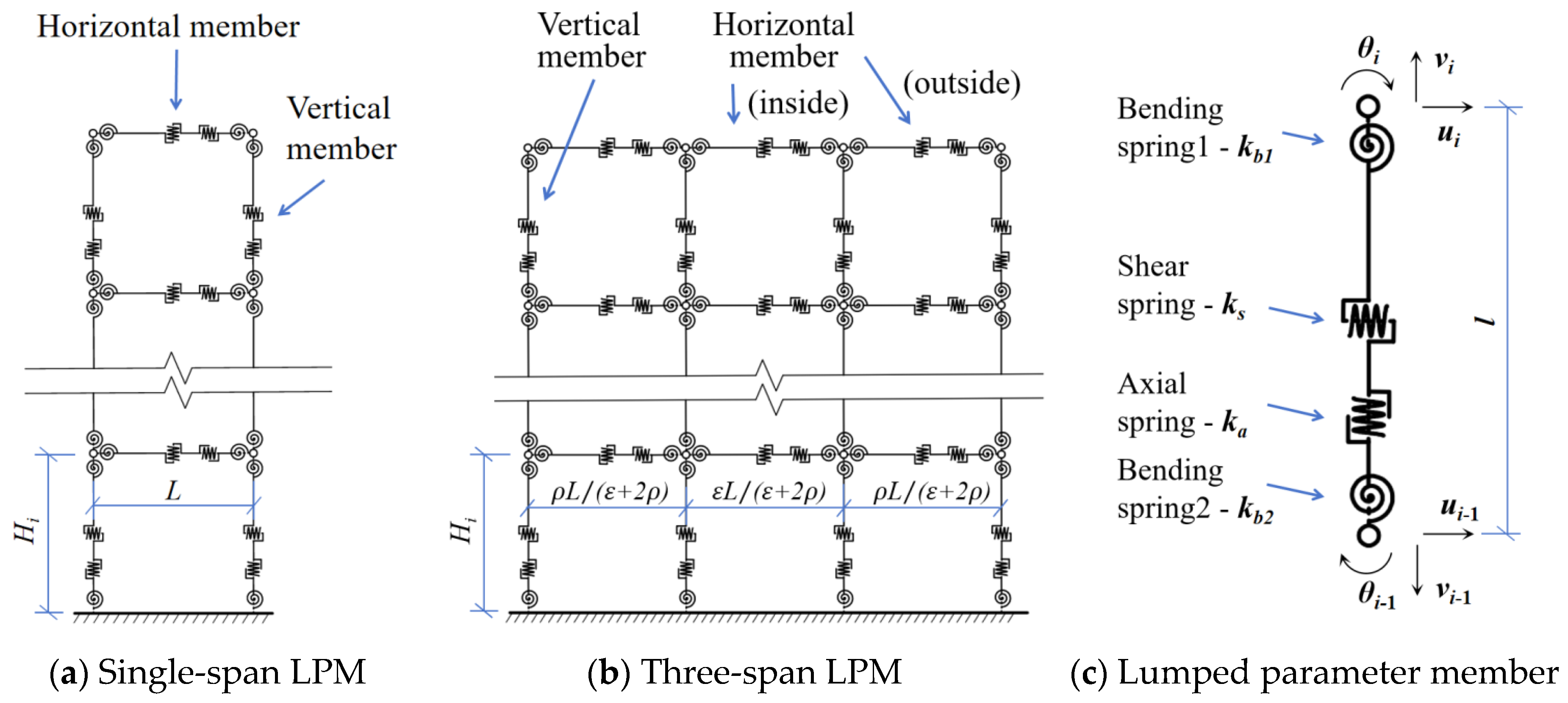
Equivalent stiffness parameters representing these components are incorporated into the LPM, as illustrated in Figure 5, to account for both the flexural resistance of horizontal members without introducing additional constraints and the anti-overturning capacity of vertical members in high-rise structures.
In the proposed enhanced LPMs, each story is modeled using vertical and horizontal members as shown in Figure 5a,b. Spring elements that represent the axial, shear, and bending stiffness of each lumped parameter member are shown in Figure 5c. The stiffness matrix relating the axial, transverse, and rotational degrees of freedom for each node of the 2-node member with lumped parameter members is given in Equations (5) and (6):
1 η k a η sym . k b 1 + k b 2 k s k b 2 k s l k b 2 k b 1 + k s l 2 k a η k a η k b 2 + k b 1 k s k b 2 k s l k b 2 + k b 1 k s k b 1 k s l k b 2 k b 1 k b 1 k s l k b 1 k b 2 + k s l 2
η = k b 1 + k b 2 + k s l 2
where ka is the axial spring stiffness; kb1 and kb2 are the bending spring stiffness, which are equal to kb to simplify the identification difficulty in the following study; ks is the shear spring stiffness; and l is the length of the member. The stiffness matrix of the enhanced LPMs can now be obtained by assembling the stiffness matrices for all members that constitute this 2-D macro model. The macro-scale model maintains consistency with the detailed FEM in terms of total height H, floor height Hi, and total width L of the building. The ratio of the lengths of the inside and outside horizontal members is controlled by coefficients ε and ρ. The complexity of a model determines its flexibility and, at the same time, the difficulty in identifying its parameters. Single-span LPM shown in Figure 5a features a concise formulation, whereas three-span LPM shown in Figure 5b incorporates an increased number of parameters to be identified for horizontal members. This enhancement, however, provides higher local FSC stiffness-flexibility, which will be demonstrated in subsequent sections. To simplify the recognition process, the axial stiffness of all the horizontal members is set to infinitely rigid. The stiffness parameters of the same type of springs for vertical members and two outside horizontal members on each floor are set to be consistent.

2.3. Parameter Identification with CNN

To make the macro-scale model (proposed enhanced LPM) consistent with the dynamic characteristics of the detailed FEM, CNNs, and model properties of the first M orders of the detailed FEM were used to recognize the stiffness parameters of the LPM. The identification process can be carried out in two stages: (1) Step 1 is with the assumption that the stiffness parameters of all floors are the same. (2) Step 2 is with the assumption that the stiffness parameters vary from story to story. In the learning process of CNN, the stiffness parameters of the enhanced LPM are set to the output parameter Poutput. For Step 1, output parameter Poutput1 is given in Equation (7):
P O u t p u t 1 = k v a k v b k v s k h b k h s k i h b k i h s
where kva, kvb, kvs are the axial, bending, shear stiffness of the vertical member; khb, khs are the bending, shear stiffness of the outside horizontal member; and kihb, kihs are the bending, shear stiffness of the inside horizontal member, respectively. In this matrix, for single-span LPM, there are no items kihb and kihs. As for Step 2, output parameter Poutput2 is given in Equation (8):
P O u t p u t 2 = K v a K v b K v s K h b K h s K i h b K i h s
where Kva, Kvb, Kvs are matrices composed of the axial, bending, shear stiffness of the vertical member of N floors; Khb, Khs are matrices composed of the bending, shear stiffness of the outside horizontal member of N floors; and Kihb, Kihs are matrices composed of the bending, shear stiffness of the inside horizontal member of N floors, respectively. In this matrix, for single-span LPM, there are also no items Kihb and Kihs.
As mentioned earlier, HBDP (αHBDPi) and DInC, given in Equations (3) and (4), offer a pathway for characterizing FSC behavior on high-rise structures. Therefore, a matrix composed of these parameters of the detailed FEM was selected as input parameters Pinput given in Equation (9):
P I n p u t = I F I L I B I D v b I D b t
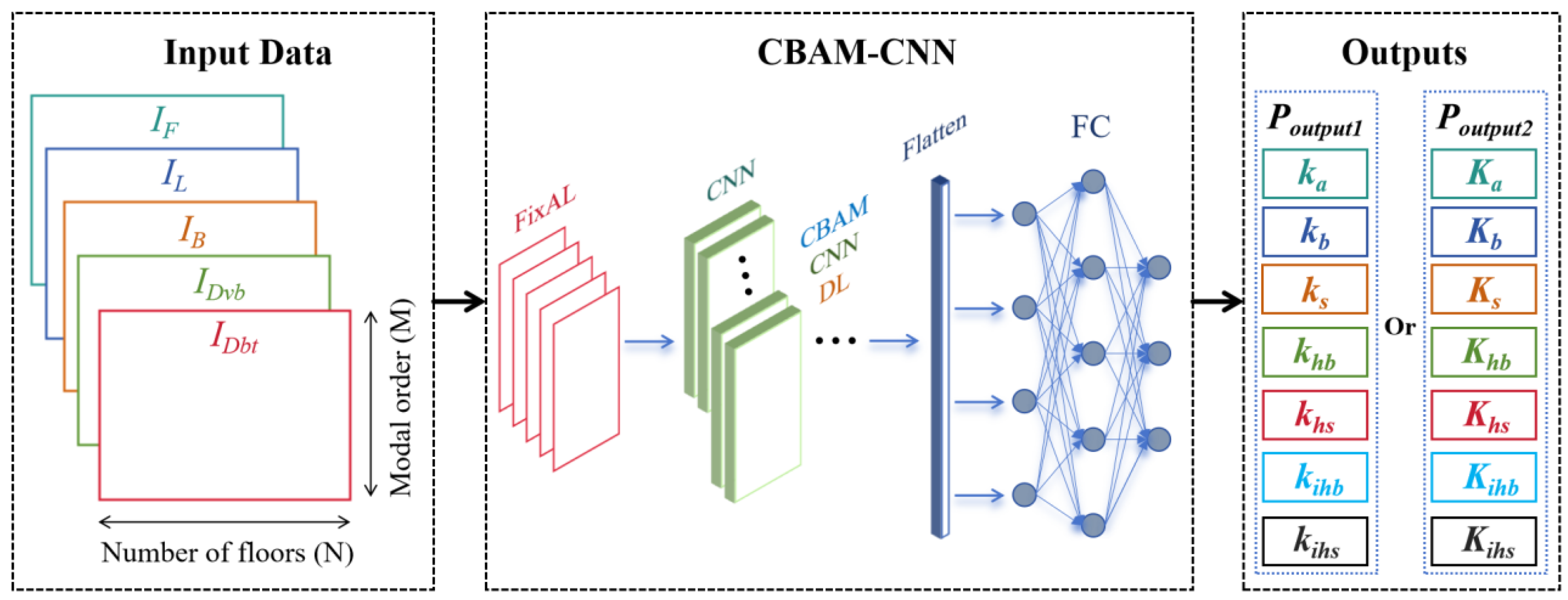
where IF, IL, IB, IDvb, IDbt are N × M matrices composed of natural frequencies (via uniform replication and padding), displacement normalized lateral vibration mode vectors, HBDP (αHBDPi), and of the detailed FEM, respectively. Given the large number of input parameters and output parameters in this study, a CNN incorporating channel and spatial attention mechanisms [24] (CBAM-CNN) was used to enhance recognition efficiency and accuracy, as illustrated in Figure 6.
For the sample data required for CNN learning, a substantial number of stiffness parameters (targets to be recognized, i.e., outputs in Figure 6) are acquired through Latin square sampling and subsequently incorporated into the proposed macro-scale model for batch processing. Thus, modal parameters of sample models (features, i.e., inputs in Figure 6) were generated. To consider the importance of different features to model recognition, a (non-learnable) Fixed attention layer (FixAL) is selectively added to manually assign weights to different features based on prior knowledge or the specific needs of a particular task [25] that would likely affect the recognition results. When verifying the similarity of the recognized macro-scaled model and detailed FEM, in addition to frequencies, the Modal Assurance Criterion (MAC) is employed to evaluate the difference between two vibration mode shapes, as expressed in Equation (10):
M A C ( ϕ D , ϕ M ) = ϕ D T ϕ M 2 ϕ D T ϕ D ϕ M T ϕ M
where ϕD is the model shapes of the detailed FEMs, and ϕM is the model shapes of the macro-scaled models. It should be noted that when calculating the Lateral MAC, matrices ϕD and ϕM represent the lateral mode shape vectors of the models, whereas for angular MAC calculation, they correspond to the angular mode shape vectors of the models. Here, the angular mode shape vectors are represented by the angles of HBDPs of the models.
During the training process, the performance metrics of the model are mainly reflected by the loss function value of the training set and that of the validation set. A good model training process is considered when both decrease simultaneously and approach each other. However, if the latter does not follow the decrease in the former, it may indicate a risk of overfitting and intervention is required. In the following case, methods such as adding a dropout layer and L2 regularization were adopted. After the training is completed, the obtained neural network model can be used to build a macro-scale model based on the dynamic characteristics of the structure (natural vibration frequency and mode shape). This model, due to its consideration of the FSC dynamic behavior and being constructed with LPM can perform structural response calculations more accurately and quickly.

3. Application in Frame and Frame-Tube Core Structures

The proposed method was applied to frame and frame-core tube structures, with its feasibility and effectiveness verified through comparative analysis of dynamic characteristics between the macro-scale models and detailed FEMs. When the high-rise structure is subjected to wind loads and seismic forces, the vibration of the structure is composed of multiple frequencies. Therefore, the degree of fitting between frequency and vibration mode is a key factor in evaluating the accuracy of the macro-scale model. Moreover, the vibration characteristics of multiple and higher orders are difficult to obtain due to their correlation with local mechanical properties. However, the method proposed in this paper provides engineering application potential for the fitting of the vibration characteristics of high-rise structures at multiple and even higher orders.

3.1. Frame Structures and Conventional Macro-Scale Model

The detailed FEM of a high-rise frame structure was constructed and shown in Figure 7. OpenSees [26] (Version 3.7.0) was imported for modal analysis and batch extraction of modal vectors. The frame has 20 floors, each with a height of 4.2 m. The vertical and horizontal members (columns and beams) were modeled using Euler-Bernoulli beam elements. To visually observe the patterns of the identified stiffness parameters of LPM, uniform member sizes and material were adopted for all structural components. All columns were box-shaped B650 × 650 × 40 sections, and all beams were H-shaped H750 × 350 × 20 × 30 × 350 × 30 sections. They were both made of Q235 carbon steel with elastic modulus: E = 2.06 × 10⁸ kN/m2; Poisson’s ratio: ν = 0.3; density: ρ = 78 kN/m3. A modal analysis was conducted, and the modal vectors at the slab nodes of each story were extracted. This study focuses on X-direction lateral vibrations, as shown in Figure 8. For the first 5 modes, HVDPs and HBDPs of all stories were extracted using mass-normalized mode shapes. Examples of this fitting for the 10th and 20th floors of the 1st mode are given in Figure 9.
A SM was constructed, and its shear stiffness of each floor was acquired by applying a unit horizontal force at the top of the detailed FEM and calculating the reciprocal of the resulting horizontal displacement. As shown in Table 1, compared to the detailed FEM, the SM model achieved a good fit in terms of the first-order frequency and horizontal vibration mode. However, its performance was unsatisfactory for higher-order frequencies, and the degrees of freedom of the model limited the representation of rotational dynamic characteristics. Meanwhile, a BM was constructed using Timoshenko-beam elements. By applying a unit bending moment at the top of the detailed FEM with an assumed rigid floor [27], the reciprocal of the floor angle was calculated to obtain the floor’s bending stiffness as a reference. The model parameters were then determined by adjusting the coefficients of Timoshenko-beam elements to make the model’s first-order frequency closely match that of the detailed FEM. As shown in Table 1, although the BM model has bending degrees of freedom, it cannot reproduce the FSC dynamic behavior of the detailed FEM, as reflected in the low Angular MAC.

3.2. Single-Span LPM for Frame Structure

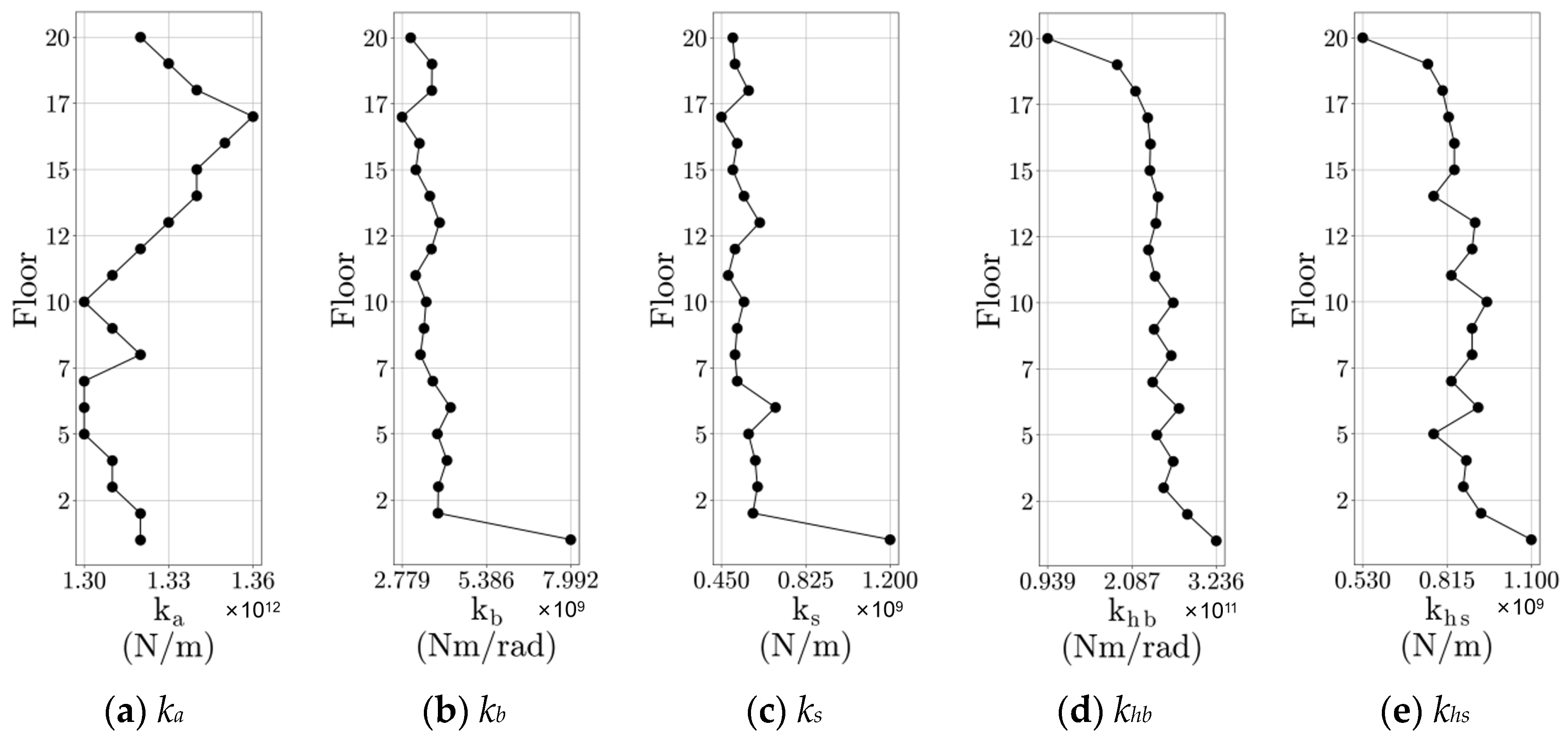
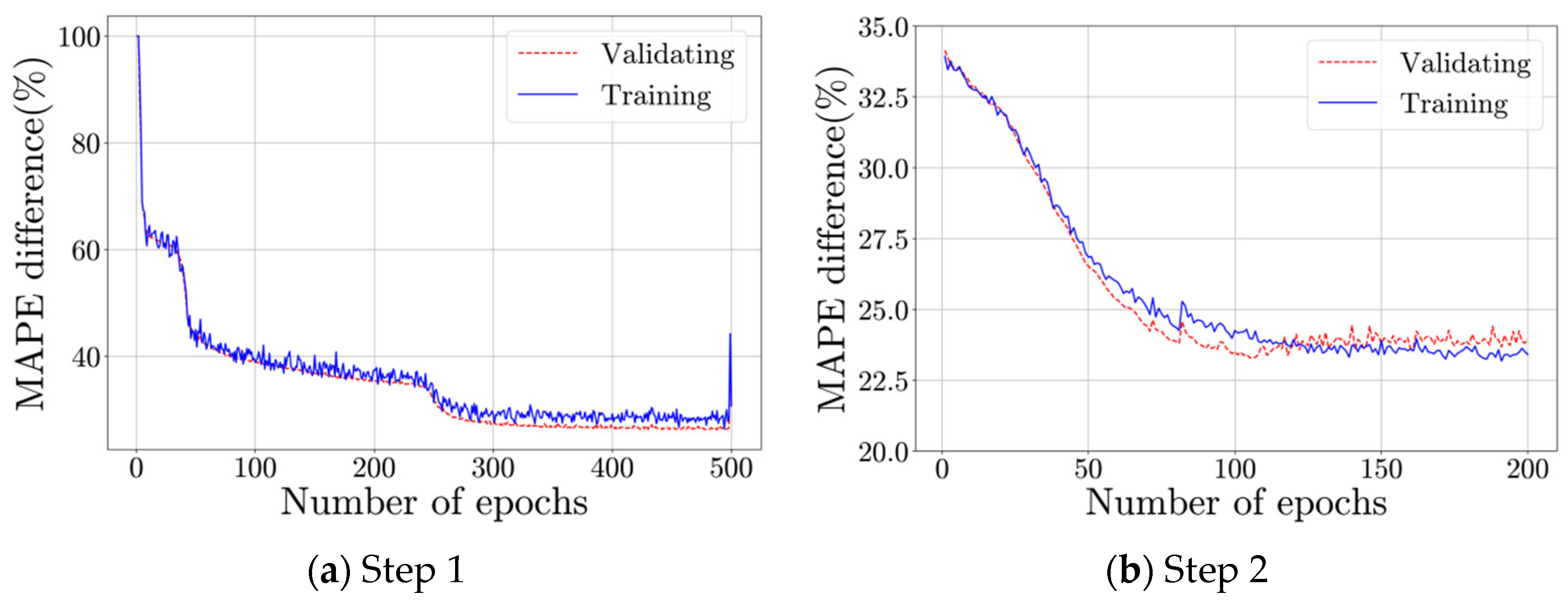
A two-stage approach is adopted for stiffness parameter identification to construct a single-span LPM for the frame structure (labeled LPM-1). In Step 1, the initial values of the model parameters were determined through a few trial calculations (provided in the Appendix A Table A1), and the change range was set to 10–1000%, with a sample size of 100,000. The dataset was split into a 75% training set and a 25% validation set. The hyperparameter settings and specific network architecture of the CNN are provided in the Appendix A Table A2 and Table A3, respectively. Dropout layer and L2 regularization were employed to prevent potential overfitting risks. A FixAL was added to amplify the natural frequencies, displacement normalized lateral vibration mode vectors, displacement normalized HBDP (αHBDPi), DBT, and DVB by a weight matrix-1 of [0.22, 0.19, 0.19, 0.20, 0.21]. Another FixAL was added to amplify the features of mode 1 to mode 5 by a weight matrix-2 of [0.22, 0.21, 0.20, 0.19, 0.18]. The learning curve is shown in Figure 10a, and the recognized stiffness parameters with the developed CNN model are provided in the Appendix A Table A1. The training was conducted on a computer with an i7-11700K processor and 128 GB of RAM, with a total training duration of 898 s.
In Step 2, the initial values of the stiffness parameters that were set with recognized values in Step 1, which are provided in the Appendix A Table A1, and the change range was set to 50–200%, with a sample size of 500,000. The dataset was split into a 75% training set and a 25% validation set.. The hyperparameter settings and specific network architecture of the CNN in Step 2 are provided in the Appendix A Table A2 and Table A3, respectively. Dropout layer and L2 regularization were employed to prevent potential overfitting risks. Two similar FixALs were added with weight matrix-1 of [0.20, 0.18, 0.21, 0.21, 0.20] and weight matrix-2 of [0.21, 0.21, 0.20, 0.19, 0.19]. The learning curve is shown in Figure 10b, and the recognized stiffness parameters with the developed CNN model are provided in Appendix A Figure A1. With the recognized stiffness parameters, LPM-1 was constructed, and modal analysis was performed. Its dynamic characteristics and mode shapes are shown in Table 2 and Figure 11, respectively. It can be observed that LPM-1 demonstrates good modeling accuracy for the first two natural frequencies. More importantly, the lateral and angular MAC values indicate that it effectively captures the FSC dynamic behavior across the first five modes. The training was conducted on the same computer with a total training duration of 2030 s.
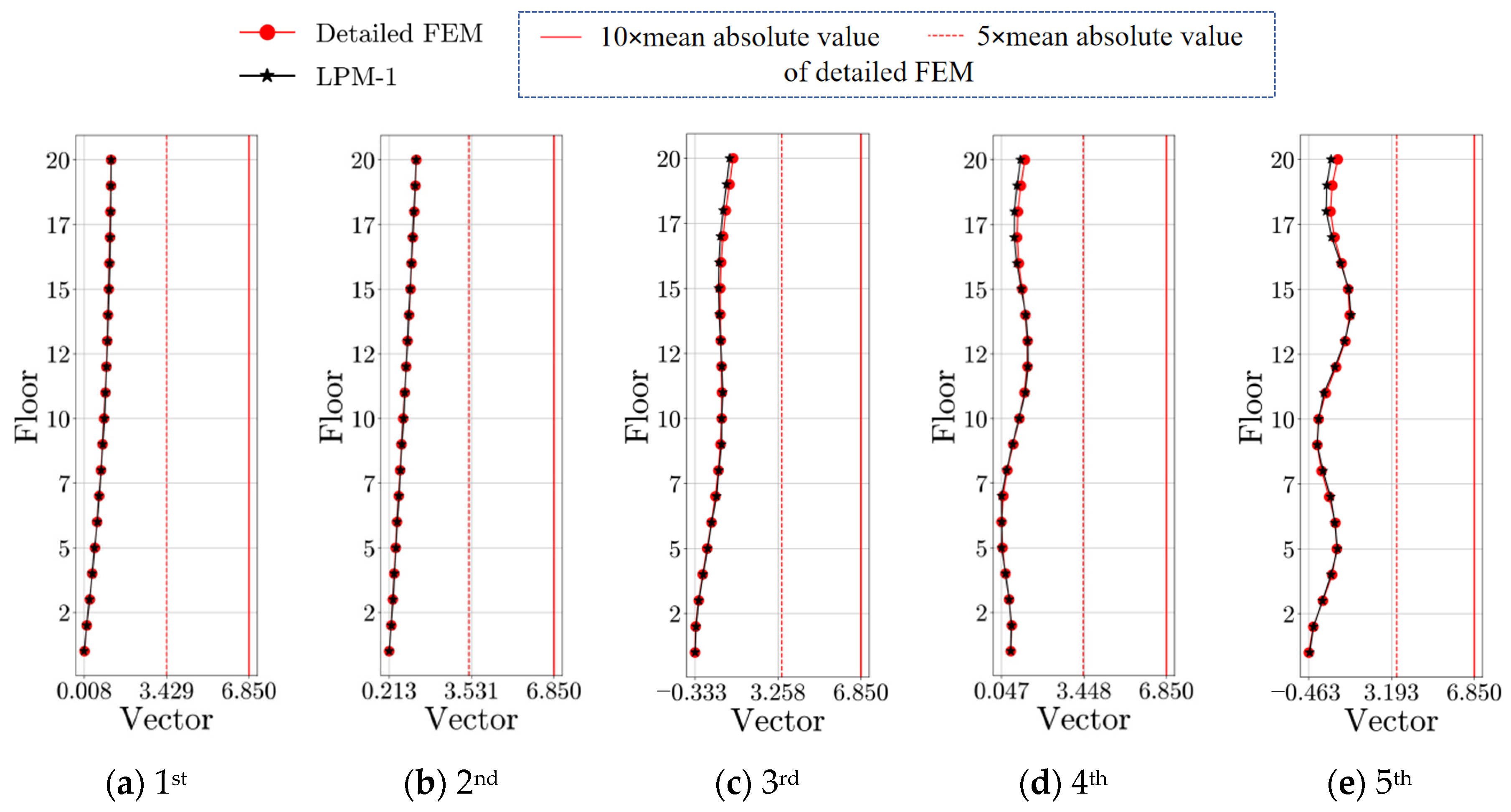
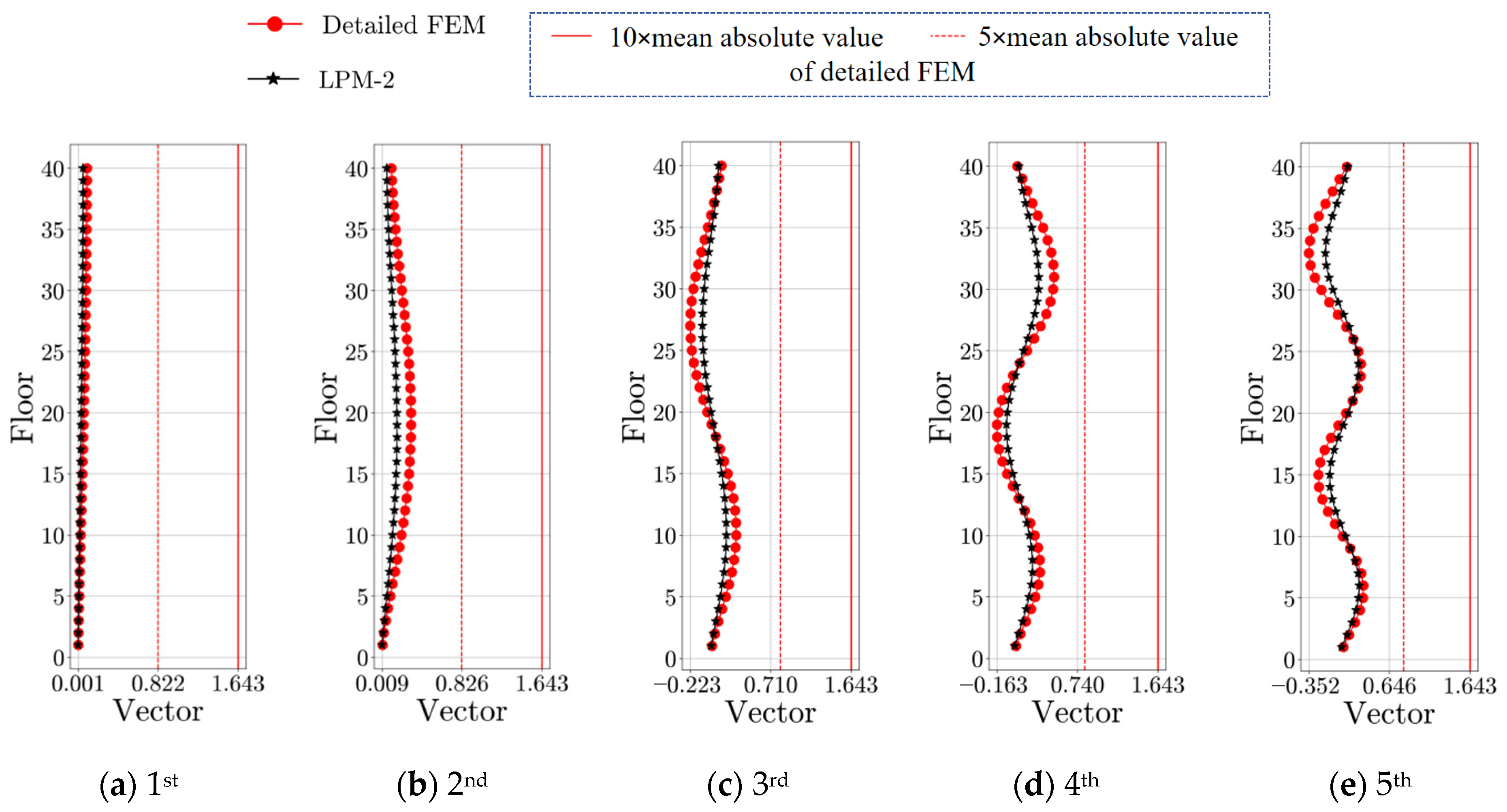
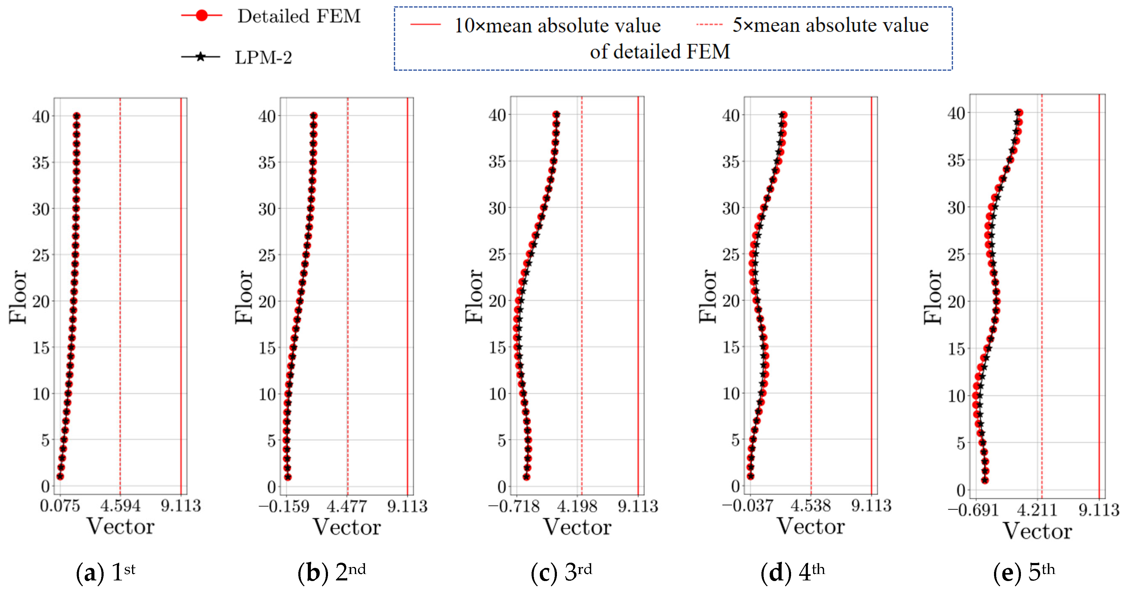
From another perspective, the fitting accuracy of LPM-1 in modeling the FSC dynamic behavior can also be evaluated using the DInC metric, with the calculated DInC values of both the detailed FEM of the high-rise frame structure and LPM-1 presented in Figure 12 and Figure 13. The red vertical dashed lines and solid lines in the figures serve as a reference representing the 5 and 10 times of the mean absolute values of the detailed FEM vectors, providing a visual and normalized measure of FSC behavior different between models. The DBTi of the BM was also calculated, showing a progressive single-directional increase in each mode, with values substantially higher than those of the detailed FEM. The reason is that, as mentioned in the previous subsection, the BM model neglects the resistance of horizontal members to the bending deformation of the floor.

3.3. Three-Span LPM for Frame-Core Tube Structure

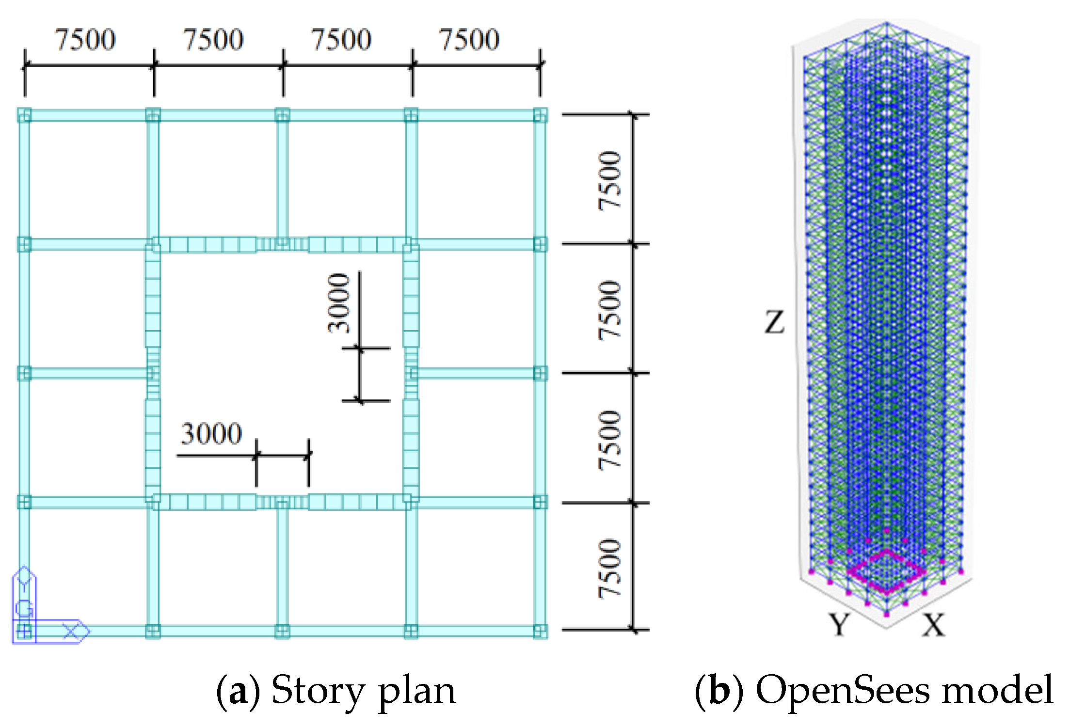
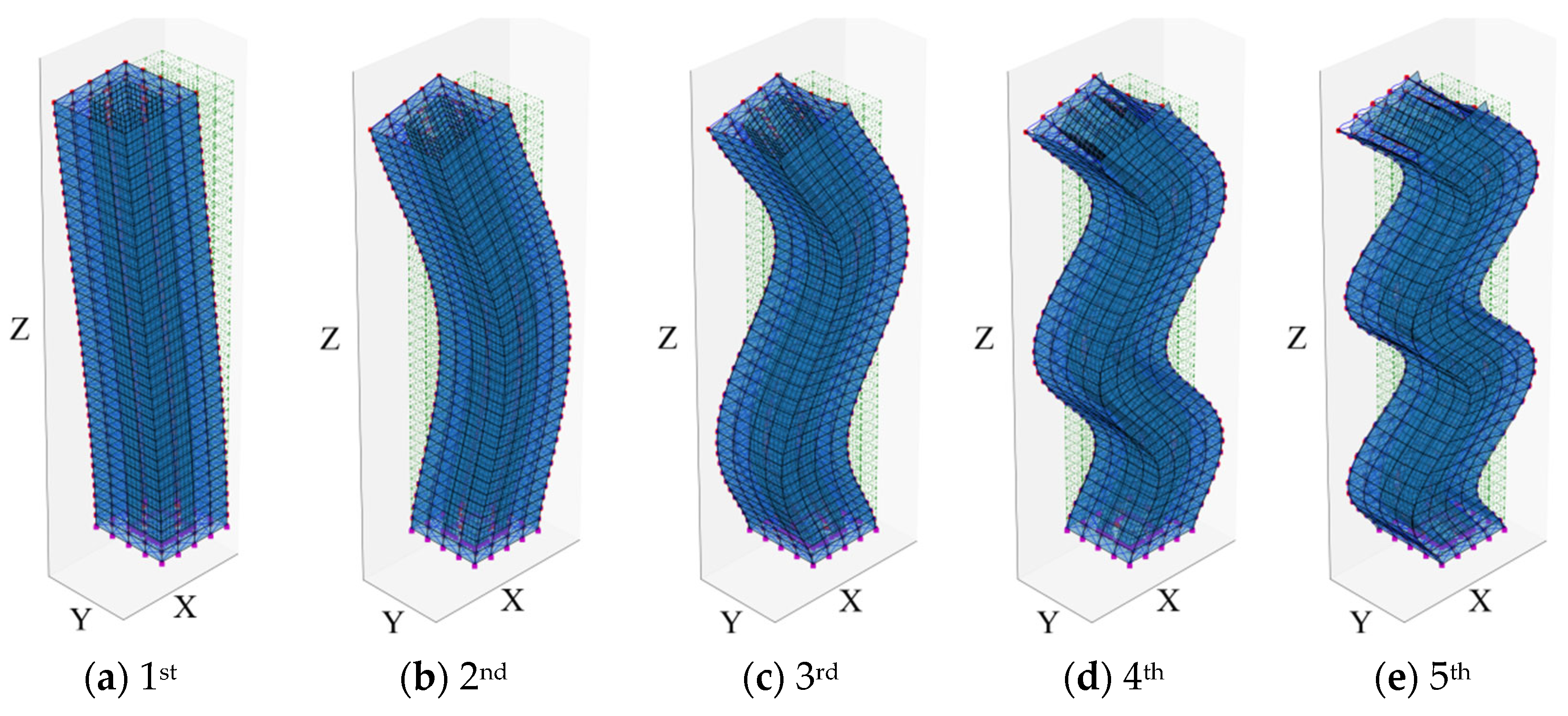
FSC dynamic behavior fitting for high-rise structures has the potential to provide a basis for the macro-scale simulation of higher-order frequencies. A limitation remains in LPM-1′s accuracy for higher-order frequency fitting, which stems from its restricted flexibility in capturing local dynamic behaviors. This can be mitigated by enhancing the model’s local stiffness complexity, as implemented in three-span LPM (Figure 5b), to improve frequency matching. To better illustrate the superior functionality of three-span LPM, a more complex high-rise frame core tube structure was chosen for model fitting, as shown in Figure 14. The structure has 40 stories, each with a height of 4.0 m. The columns and beams were modeled using Euler-Bernoulli beam elements, and the core wall was modeled using shell elements. Uniform member sizes and materials were adopted for all structural components. All columns were 800 × 800 mm2 rectangular C40-RC columns, and all beams were 500 × 1000 mm2 rectangular C30-RC beams, except for the coupling beams in the core wall, which have a cross-section of 700 × 1400 mm2. The material properties are: C30 concrete (E = 3.0 × 10⁷ kN/m2, ν = 0.25, ρ = 25 kN/m3) and C40 concrete (E = 3.25 × 10⁷ kN/m2, with ν and ρ assumed identical to C30). The wall thickness of the core tube is 900 mm. This model also incorporates simplified simulations of infill walls, exterior curtain walls, and rigid panel zones, which, due to space limitations, are not discussed in detail in this paper. Similarly, modal analysis of the structure was conducted under the assumption that deformations were restricted to the X-direction, as shown in Figure 15.
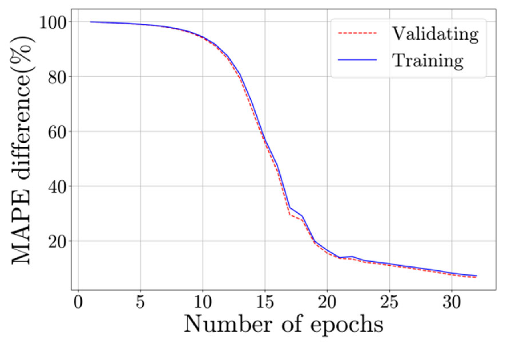
A macro-scale model in the form of three-span LPM (Figure 5b) was constructed (labeled as LPM-2). Coefficients ε and ρ were set as 2 and 1, respectively. Only one step (Step-1) stiffness identification method was adopted since a good fitting effect has been achieved. The initial values of the stiffness parameters were determined through a few trial calculations (provided in the Appendix A Table A1). 15,000 samples were generated with the combination of different stiffness change ranges (5000 samples with 80–120% variation ranges, and 10,000 samples with 90–110% variation ranges) and batch modal analysis. The dataset was split into a 75% training set and a 25% validation set. Dropout layer and L2 regularization were employed to prevent potential overfitting risks. FixAL was set as: weight matrix-1 [0.57, 0.10, 0.10, 0.10, 0.10]; The weight matrix-2 is [0.72, 0.14, 0.06, 0.04, 0.03] for frequency components, and [0.37, 0.28, 0.20, 0.12, 0.03] for other components. The hyperparameter settings and specific network architecture of the CBAM-CNN are provided in the Appendix A Table A2 and Table A3, respectively. The training was conducted on the same computer with a total training duration of 291 s.
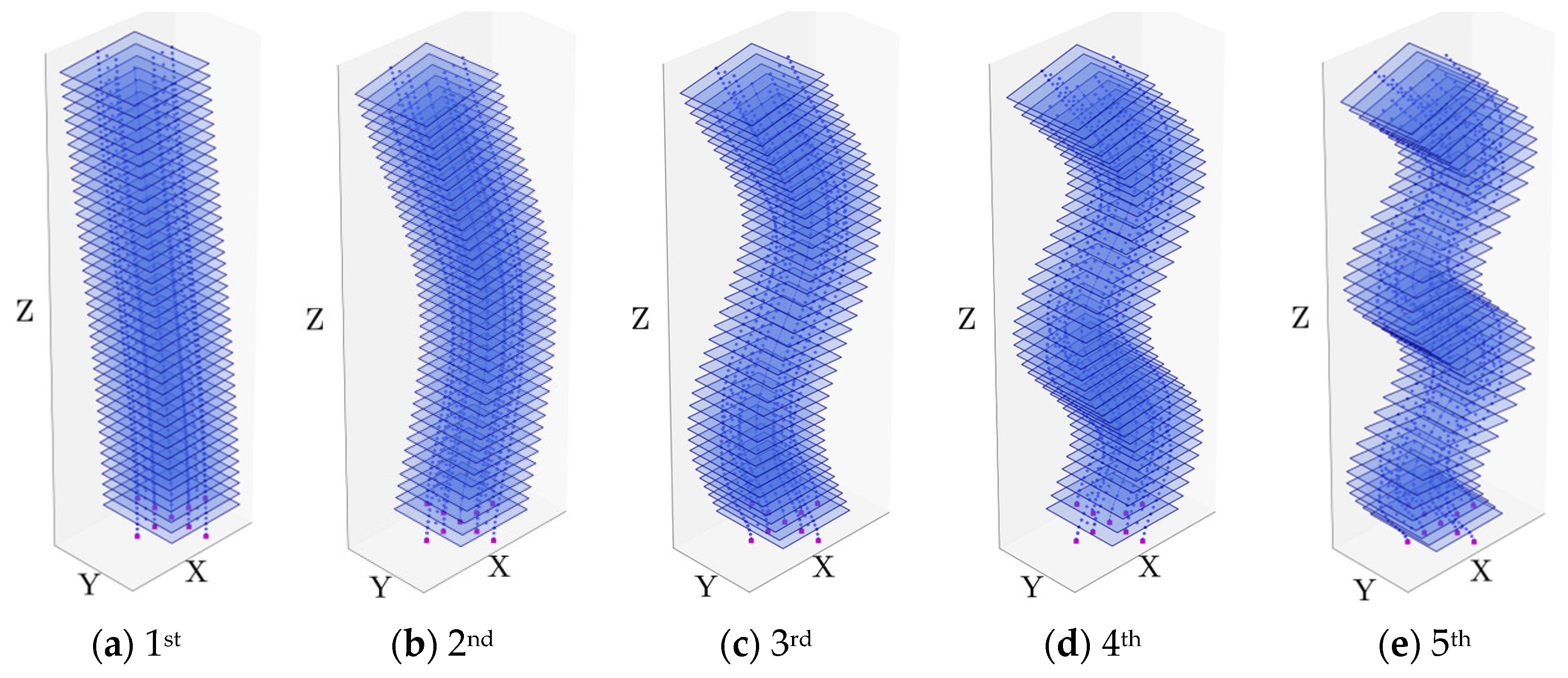
The learning curve is shown in Figure 16, and the recognized stiffness parameters with the developed CNN model are provided in the Appendix A Table A2. With the recognized stiffness parameters, the macro-scale model of the high-rise frame core tube building was constructed. The modal analysis of the CNN-recognized LPM-2 was conducted as shown in Table 3 and Figure 17, as well as the dynamic properties of the detailed FEM. It can be observed that LPM-2 demonstrates good modeling accuracy for all the first five natural frequencies. Meanwhile, the lateral and angular MAC values indicate that it effectively captures the FSC dynamic behavior across the first five modes. Similarly, this is also demonstrated by the DInC metric as shown in Figure 18 and Figure 19. It can be anticipated that LPM-2 has greater fitting potential in the model identification of Step 2 (where stiffness coefficients vary across floors), but at the cost of higher identification expenses and computational power requirements.

4. Conclusions

This paper proposes a macro-scale modeling method with FSC dynamic behavior in high-rise structures using DL, specifically CNN. By establishing DInC under each mode shape, the coupling effects of horizontal, vertical, and bending displacements at different floors are quantified to describe the FSC dynamic behavior in high-rise structures. To account for the flexural resistance of horizontal members without introducing additional constraints and the anti-overturning contribution of vertical members, which explicitly represent story inclination mechanisms, equivalent stiffness parameters representing horizontal and vertical members are introduced into the LPM, enhancing the flexibility of the macro-scale model in expressing FSC dynamic behavior. Furthermore, DInCs are integrated as input features for CNN to identify the equivalent stiffness parameters of the enhanced LPM, thereby achieving the macro-scale modeling of the FSC dynamic behavior in high-rise structures. The proposed method was applied to frame and frame-core tube structures, with its feasibility and effectiveness verified through comparative analysis of dynamic characteristics and DInCs between the macro-scale models and detailed FEM.
In this study, the single-span LPM can already achieve good fitting results for the first two modes in terms of frequencies and FSC dynamic behavior. In contrast, three-span LPM shows greater capacity in fitting higher-order vibration modes, though it inevitably increases identification difficulty and computational cost. In practical engineering applications, the choice between Single-span LPM and three-span LPM depends on the trade-off between the required accuracy of dynamic characteristics fitting in the macro-scale model and computational efficiency, as well as the complexity of the simulation target.
The macro-scale models developed in this study can more accurately capture the dynamic behavior of high-rise structures while offering greater flexibility. This makes them particularly suitable for engineering applications that require highly precise and efficient calculations of structural characteristics or responses—such as seismic analysis and design optimization of high-rise structure. By integrating monitoring and identification of the global dynamic properties of real high-rise structures with recorded floor-level responses under seismic or typhoon loads, the proposed approach establishes a theoretical foundation for achieving accurate and rapid macro-scale digital twins of actual high-rise structures.
The application of the proposed method to real high-rise structures remains challenging and warrants further research. For instance, some areas of improvement include more precise reproduction of FSC dynamic behavior, application to high-rise buildings with bracing, spandrels, and belt trusses, etc., as the addition of these lateral force-resisting systems can drastically change the dynamic characteristics of these buildings. However, the simplicity, flexibility, and adaptability of the proposed macro-scale model and the accuracy of the recognition method make a potential extension of the model to accurately represent the dynamic behavior of real-life structures attainable.

Author Contributions

Conceptualization, H.S. and J.T.; Methodology, W.L. and E.M.L.; Software, H.S. and W.Z.; Validation, H.S.; Investigation, W.Z.; Writing—original draft, H.S.; Writing—review & editing, W.L. and E.M.L.; Visualization, H.S.; Supervision, W.H. and J.T.; Funding acquisition, W.L., W.H. and J.T. All authors have read and agreed to the published version of the manuscript.

Funding

This research was funded by the National Key Research and Development Program of China [grant numbers 2024YFC3810504], National Natural Science Foundation of China [grant numbers 52438004, 52122804, 52378296], and the Fundamental Research Project of Shenzhen Science and Technology Plan [grant number JCYJ20240813110403005].

Data Availability Statement

The original contributions presented in the study are included in the article, further inquiries can be directed to the corresponding author.

Conflicts of Interest

The authors declare no conflicts of interest.

Appendix A

Table A1. Stiffness parameters of LPM.
Stiffness ParametersInitial ValuesRecognized Values
LPM-1 (Step-1)LPM-2LPM-1 (Step-1)LPM-2
k a (N/m)1.20 × 10127.00 × 1071.42 × 10126.96 × 107
k b (Nm/rad)3.50 × 1091.50 × 10143.57 × 1091.45 × 1014
k s (N/m) 7.50 × 1081.00 × 10125.74 × 1089.92 × 1011
k h b (Nm/rad)2.00 × 10118.00 × 10132.10 × 10117.98 × 1013
k h s (N/m)3.00 × 1091.00 × 10148.18 × 1099.99 × 1013
k i h b (Nm/rad)-4.00 × 1013-3.95 × 10¹⁰
k i h s (N/m)-1.00 × 1014-1.00 × 10¹³
Table A2. Hyperparameter settings of the CNN.
ParametersLPM-1 (Step 1)LPM-1 (Step 2)LPM-2
Number of epochs50020032
Batch size2562562048
Learning rate0.020.10.0001
Kernel size of Conv3d3 × 3 × 33 × 3 × 33 × 3 × 3
Weight decay (L2 regularization)1.0 × 10−81.0 × 10−101.0 × 10⁻³
Dropout rate0.30.10.2
Table A3. Specific network architecture of the CNN.
LayerTypeOutput Size
LPM-1(Step 1)LPM-1(Step 2)LPM-2
InputModal databs 1 × 1 × 5 × 5 × 20bs × 1 × 5 × 5 × 40
FixAL 2Weight matrix-1bs × 1 × 5 × 5 × 20bs × 1 × 5 × 5 × 40
Weight matrix-2bs × 1 × 5 × 5 × 20bs × 1 × 5 × 5 × 40
CNN 3Conv3dbs × 32 × 5 × 5 × 20bs × 16 × 5 × 5 × 40
ReLU--
Max poolingbs × 32 × 2 × 2 × 10bs × 16 × 2 × 2 × 20
CBAM 4Channel attentionbs × 32 × 2 × 2 × 10-
Spatial attentionbs × 32 × 2 × 2 × 10
CNNConv3dbs × 64 × 2 × 2 × 10bs × 32 × 2 × 2 × 20
ReLU--
Max poolingbs × 64 × 1 × 1 × 5bs × 32 × 2 × 2 × 10
CNNConv3d-bs × 64 × 2 × 2 × 10
ReLU-
Max poolingbs × 64 × 1 × 1 × 5
CBAMChannel attention-bs × 64 × 1 × 1 × 5
Spatial attentionbs × 64 × 1 × 1 × 5
DL 5---
FC 6Flattenbs × 320bs × 320bs × 320
FC cellsbs × 64bs × 256bs × 1000
ReLU---
FC cellsbs × 16bs × 128bs × 640
ReLU---
FC cellsbs × 5bs × 100bs × 256
OutputStiffness parametersbs × 5bs × 100bs × 7
1 Batch size. 2 Fixed attention layer. 3 Convolutional layer. 4 Convolutional block attention module. 5 Dropout layer. 6 Fully connected layer.
Figure A1. Recognized stiffness parameters of LPM-1 in Step 2.
Buildings 15 03727 g0a1

References

  1. Zhou, K.; Li, Q.S.; Li, X. Dynamic behavior of supertall building with active control system during Super Typhoon Mangkhut. J. Struct. Eng. 2020, 146, 04020077. [Google Scholar] [CrossRef]
  2. Naeim, F.; Lew, M.; Carpenter, L.D.; Youssef, N.F.; Rojas, F.; Saragoni, G.R.; Adaros, M.S. Performance of tall buildings in Santiago, Chile during the 27 February 2010 offshore Maule, Chile earthquake. Struct. Des. Tall. Build. 2011, 20, 1–16. [Google Scholar] [CrossRef]
  3. Yu, S.; Guo, T.; Wang, Y.; Han, X.; Du, Z.; Wang, J. Visualization of regional seismic response based on oblique photography and point cloud data. Structures 2023, 56, 104916. [Google Scholar] [CrossRef]
  4. Xu, Z.; Chen, J.; Shen, J.; Xiang, M. Regional-scale nonlinear structural seismic response prediction by neural network. Eng. Fail. Anal. 2023, 154, 107707. [Google Scholar] [CrossRef]
  5. Lam, H.F.; Hu, J.; Yang, J.H. Bayesian operational modal analysis and Markov chain Monte Carlo-based model updating of a factory building. Eng. Struct. 2017, 132, 314–336. [Google Scholar] [CrossRef]
  6. Prajapat, K.; Ray-Chaudhuri, S. Prediction error variances in Bayesian model updating employing data sensitivity. J. Eng. Mech. 2016, 142, 04016096. [Google Scholar] [CrossRef]
  7. Sun, H.; Büyüköztürk, O. Probabilistic updating of building models using incomplete modal data. Mech. Syst. Signal. Process. 2016, 75, 27–40. [Google Scholar] [CrossRef]
  8. Deng, Y.; Li, Y.; Li, A. Seismic safety assessments of historical timber buildings using updated finite element models: Case study of Yingxian wooden pagoda, China. J. Build. Eng. 2023, 63, 105454. [Google Scholar] [CrossRef]
  9. Lee, D.G.; Kim, H.S.; Chun, M.H. Efficient seismic analysis of high-rise building structures with the effects of floor slabs. Eng. Struct. 2002, 24, 613–623. [Google Scholar] [CrossRef]
  10. Minami, Y.; Yoshitomi, S.; Takewaki, I. System identification of super high-rise buildings using limited vibration data during the 2011 Tohoku (Japan) earthquake. Struct. Control Health Monit. 2013, 20, 1317–1338. [Google Scholar] [CrossRef]
  11. Encina, J.; de la Llera, J.C. A simplified model for the analysis of free plan buildings using a wide-column model. Eng. Struct. 2013, 56, 738–748. [Google Scholar] [CrossRef]
  12. Pan, Y.; Ventura, C.E.; Xiong, H.; Zhang, F.L. Model updating and seismic response of a super tall building in Shanghai. Comput. Struct. 2020, 239, 106285. [Google Scholar] [CrossRef]
  13. Shan, J.; Zhuang, C.; Chao, X.; Loong, C.N. Model updating of a shear-wall tall building using various vibration monitoring data: Accuracy and robustness. Struct. Des. Tall. Spec. Build. 2024, 33, e2114. [Google Scholar] [CrossRef]
  14. Amoussou, C.P.D.; Lei, H.; Alhaddad, W.; Halabi, Y. Simplified modeling and analysis method for skyscrapers with outrigger system. Structures 2021, 33, 1033–1050. [Google Scholar] [CrossRef]
  15. Li, X.; Kurata, M. Probabilistic updating of fishbone model for assessing seismic damage to beam–column connections in steel moment-resisting frames. Comput.-Aided Civ. Infrastruct. Eng. 2019, 34, 790–805. [Google Scholar] [CrossRef]
  16. Qu, Z.; Gong, T.; Li, Q.; Wang, T. Evaluation of the fishbone model in simulating the seismic response of multistory reinforced concrete moment-resisting frames. Earthq. Eng. Eng. Vib. 2019, 18, 315–330. [Google Scholar] [CrossRef]
  17. Tang, Y.; Cai, C.; Xie, Y. Improved lumped parameter model for shear wall–frame structures with geometric and material nonlinearities. J. Build. Eng. 2024, 91, 109633. [Google Scholar] [CrossRef]
  18. Ji, X.; Fenves, G.L.; Kajiwara, K.; Nakashima, M. Seismic damage detection of a full-scale shaking table test structure. J. Struct. Eng. 2011, 137, 14–21. [Google Scholar] [CrossRef]
  19. Shan, J.; Zhuang, C.; Loong, C.N. Parametric identification of Timoshenko-beam model for shear-wall structures using monitoring data. Mech. Syst. Signal. Process. 2023, 189, 110100. [Google Scholar] [CrossRef]
  20. Zapico, J.L.; González, M.P. Numerical simulation of a method for seismic damage identification in buildings. Eng. Struct. 2006, 28, 255–263. [Google Scholar] [CrossRef]
  21. González, M.P.; Zapico, J.L. Seismic damage identification in buildings using neural networks and modal data. Comput. Struct. 2008, 86, 416–426. [Google Scholar] [CrossRef]
  22. Li, Z.; Liu, F.; Yang, W.; Peng, S.; Zhou, J. A survey of convolutional neural networks: Analysis, applications, and prospects. IEEE. Trans. Neural. Netw. 2021, 33, 6999–7019. [Google Scholar] [CrossRef]
  23. Yao, G.; Lei, T.; Zhong, J. A review of convolutional-neural-network-based action recognition. Pattern. Recognit. Lett. 2019, 118, 14–22. [Google Scholar] [CrossRef]
  24. Woo, S.; Park, J.; Lee, J.Y.; Kweon, I.S. Cbam: Convolutional block attention module. In Proceedings of the European Conference on Computer Vision (ECCV), Munich, Germany, 8–14 September 2018; pp. 3–19. Available online: https://link.springer.com/conference/eccv (accessed on 5 October 2024).
  25. Zhang, L.; Cosmo, L.; Minello, G.; Torsello, A.; Rossi, L. GraFix: A graph transformer with fixed attention based on the wl kernel. In Lecture Notes in Computer Science, Proceedings of the International Conference on Pattern Recognition, Kolkata, India, 1–5 December 2024; Springer Nature: Cham, Switzerland, 2024; Volume 15304, pp. 435–450. [Google Scholar] [CrossRef]
  26. McKenna, F.; Scott, M.H.; Fenves, G.L. Nonlinear finite-element analysis software architecture using object composition. J. Comput. Civ. Eng. 2010, 24, 95–107. [Google Scholar] [CrossRef]
  27. Chen, W.H.; Lu, Z.R.; Lin, W.; Chen, S.H.; Ni, Y.Q.; Xia, Y.; Liao, W.Y. Theoretical and experimental modal analysis of the Guangzhou New TV Tower. Eng. Struct. 2011, 33, 3628–3646. [Google Scholar] [CrossRef]
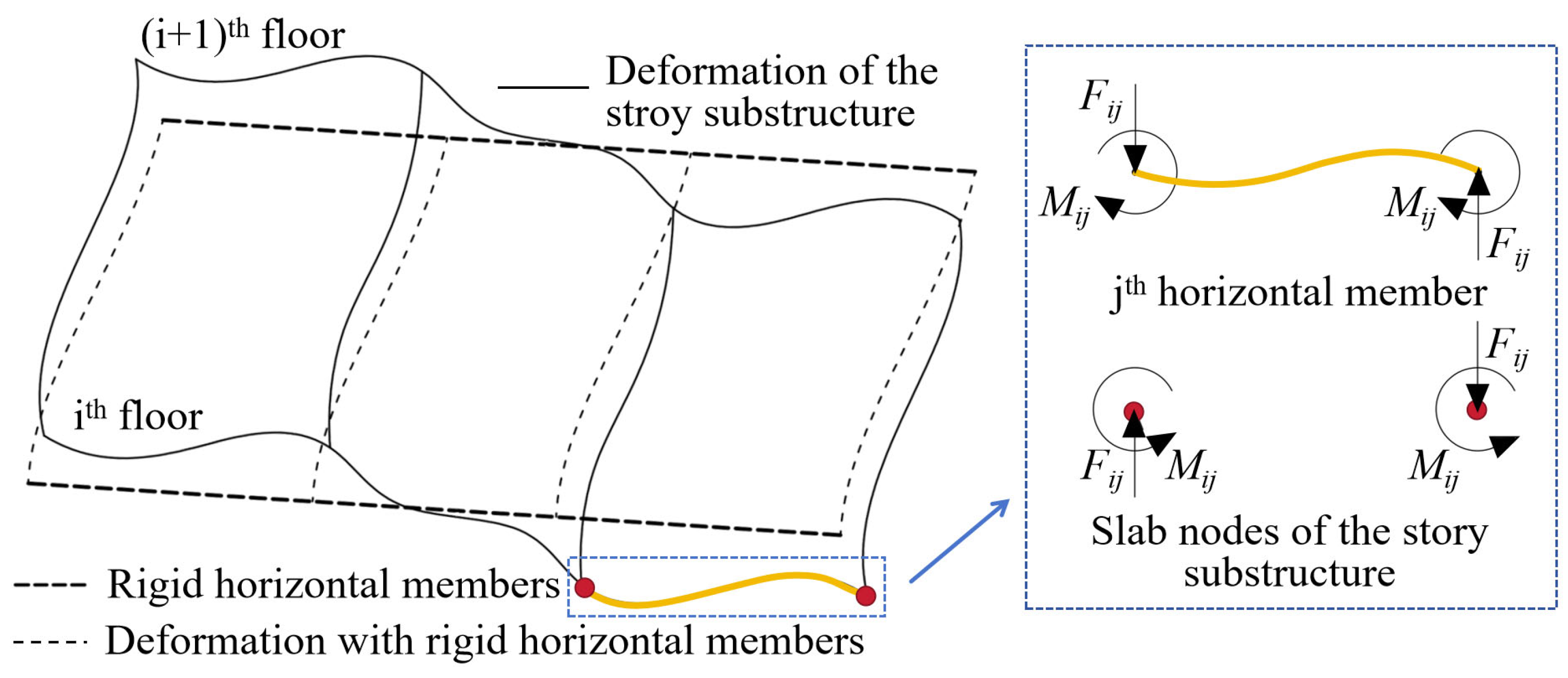
Figure 1. The horizontal members provide resistance moment and vertical force against the rotation of the floor node.
Buildings 15 03727 g001
Figure 2. Schematic overview of the macro-scale modeling approach.
Buildings 15 03727 g002
Figure 3. Displacement diagram of slab nodes.
Buildings 15 03727 g003
Figure 4. Story-bending deformation diagram.
Buildings 15 03727 g004
Figure 5. Enhanced LPMs for FSC dynamic behavior.
Buildings 15 03727 g005
Figure 6. CNN model construction.
Buildings 15 03727 g006
Figure 7. A high-rise frame structure.
Buildings 15 03727 g007
Figure 8. Lateral mode shapes of the high-rise frame structure.
Buildings 15 03727 g008
Figure 9. HVDPs and HBDPs of the 1st mode of the frame structure.
Buildings 15 03727 g009
Figure 10. Mean Absolute Percent Error (MAPE) difference in LPM-1.
Buildings 15 03727 g010
Figure 11. Lateral modal vectors of the LPM-1.
Buildings 15 03727 g011
Figure 12. DBTi of the models.
Buildings 15 03727 g012
Figure 13. DVBi of the models.
Buildings 15 03727 g013
Figure 14. A high-rise frame core tube structure.
Buildings 15 03727 g014
Figure 15. Lateral mode shapes of the high-rise frame core tube structure.
Buildings 15 03727 g015
Figure 16. MAPE of LPM-2.
Buildings 15 03727 g016
Figure 17. Lateral mode shapes of the LPM-2.
Buildings 15 03727 g017
Figure 18. DBTi of the detailed FEM and LPM-2.
Buildings 15 03727 g018
Figure 19. DVBi of the detailed FEM and LPM-2.
Buildings 15 03727 g019
Table 1. Dynamic properties of the frame structure and conventional models.
Modal OrderDetailed FEMSMBM
Freq. 1 (Hz)Freq. (Hz)Δf 2 (%)Lateral MAC (%)Freq. (Hz)Δf (%)Lateral MAC (%)Angular MAC (%)
10.300.30−0.230.99990.300.130.99980.8314
20.920.88−4.550.99940.90−1.640.99740.7233
31.621.45−10.450.99821.59−2.260.99230.5006
42.352.02−14.040.99542.22−5.730.98440.3437
53.142.58−18.120.99182.84−9.640.97760.2385
1 Natural vibration frequency. 2 Difference in the frequencies between the macro-scale model and the detailed FEM.
Table 2. Dynamic properties of the LPM-1.
Modal OrderFreq. 1 (Hz)Δf 2 (%)Lateral MAC (%)Angular MAC (%)
10.300.940.99970.9963
20.90−1.770.99950.9995
31.47−10.010.99920.9986
42.09−12.290.99840.9979
52.67−17.820.9540.9879
1 Natural vibration frequency. 2 Difference in the frequencies between the macro-scale model and the detailed FEM.
Table 3. Dynamic properties of the high-rise frame core tube structure and LPM-2.
Modal OrderDetailed FEM Freq. 1 (Hz)LPM-2 Freq. 1 (Hz)Δf 2 (%)Lateral MAC (%)Angular MAC (%)
10.350.361.190.99990.9984
21.431.411.070.99990.9984
33.002.941.581.00000.9990
44.674.581.370.99980.9986
56.546.401.330.99950.9984
1 Natural vibration frequency. 2 Difference in the frequencies between the macro-scale model and the detailed FEM.
Disclaimer/Publisher’s Note: The statements, opinions and data contained in all publications are solely those of the individual author(s) and contributor(s) and not of MDPI and/or the editor(s). MDPI and/or the editor(s) disclaim responsibility for any injury to people or property resulting from any ideas, methods, instructions or products referred to in the content.