Article

Parametric Analysis of Steel Studs to Reduce Thermal Bridges in Light Steel Framing Construction Systems

by
Marcelo Langner
1,
Thais A. Soares
1,
António Figueiredo
1,
Ricardo M. S. F. Almeida
2,3,* and
Romeu Vicente
1
1
CERIS—Civil Engineering Research and Innovation for Sustainability, Civil Engineering Department, University of Aveiro, Campus Universitário de Santiago, 3810-193 Aveiro, Portugal
2
Department of Civil Engineering, Polytechnic Institute of Viseu, Campus Politécnico de Repeses, 3504-510 Viseu, Portugal
3
Institute of R&D in Structures and Construction-LFC (CONSTRUCT-LFC), Faculty of Engineering (FEUP), University of Porto, Rua Dr. Roberto Frias s/n, 4200-465 Porto, Portugal
*
Author to whom correspondence should be addressed.
Buildings 2025, 15(2), 194; https://doi.org/10.3390/buildings15020194
Submission received: 5 December 2024 / Revised: 4 January 2025 / Accepted: 8 January 2025 / Published: 10 January 2025
(This article belongs to the Section Building Energy, Physics, Environment, and Systems)

Abstract

Thermal bridges significantly affect the thermal performance of light steel framing systems due to the high thermal conductivity of steel. The objective of this study is to identify modifications on the steel profiles to reduce heat flux and improve the thermal resistance of both single- and double-layer wall panels. Three approaches were analyzed: (i) slotted steel studs, (ii) integration of less-conductive materials into the web section, and (iii) modifications to web geometry. A numerical model was calibrated based on experimental data and used to perform dynamic simulations with different configurations. Results show that incorporating less-conductive materials, such as rigid polyamide, achieved a heat flux reduction of up to 98%, while optimized slotted patterns reduced heat flux by up to 90%. The results also demonstrated that all web modifications effectively reduced heat flux through the wall, with approaches (i) and (ii) showing the greatest impact. The shape of the slots also has an important impact on the heat flux. The most effective strategy for enhancing the thermal performance of the steel studs was the use of a less-conductive material.

1. Introduction

The building sector has attracted global attention as a key contributor to energy-related issues, being responsible for approximately 30% of CO2 emissions and 40% of global energy consumption in the European Union (EU) [1]. In this total, the consumption for heating and cooling accounts for 50%, of which 80% is used in buildings [2,3].
In response to this alarming scenario, the construction sector has been developing and investing in lower-impact building systems [4,5]. The industrialized and lightweight systems have been one of the choices as an alternative to heavyweight masonry and reinforced concrete systems [6,7].
Studies by Roque et al. have investigated the thermal performance of two identical test cells, one constructed with a Light Steel Frame (LSF) system and the other with heavy masonry, through long-term experimental campaigns. The test cells were monitored over an entire year, providing valuable insights into their behavior under real climatic conditions. The results demonstrated that the LSF test cell consistently exhibited lower energy consumption across all monitored months. However, it also showed higher responsiveness to external weather variations, making it more susceptible to nocturnal temperature drops and overheating during warmer periods. These findings highlight the potential and challenges of the LSF constructive system when compared to heavy masonry, particularly in terms of energy efficiency and indoor thermal comfort [8,9,10].
In addition, the light steel framing (LSF) system is an option that offers advantages such as reduced weight, which makes transportation and handling easier, faster construction on site, reduced waste and water consumption (dry construction) and quality control that comes with prefabrication processes [11,12].
Nevertheless, due to the high thermal conductivity of the steel structure, the LSF system is prone to the formation of thermal bridges [13,14] that can affect the energy efficiency of the building, increasing the heating demand by approximately 30% and the cooling demand by up to 20% [15]. This thermal inefficiency of the envelope can result in thermal discomfort for the occupants, and in certain cases, it could originate in moisture condensation and mold growth [16,17]. Therefore, the need to investigate patterns and solutions to minimize the effects of the thermal bridges in LSF systems is fundamental. Regarding this issue, several authors have been investigating the unfavorable influence of thermal bridges in light steel systems, proposing new methods for its quantification in terms of heat losses [18,19,20].
Among the strategies to mitigate these effects, thermoprofiles have shown promising results by incorporating slots into the web section of steel profiles. These perforations disrupt the heat flux path, reducing thermal bridging and enhancing the overall thermal resistance of the element [21].
In terms of overall design, the strategies for reducing thermal bridges identified in the literature include avoiding interruptions in the insulation layers on the outside of the steel frame, joining the insulation layers over their full width at junctions, using low thermal conductivity fasteners to attach the studs to the insulation layer, and keeping the geometry of the façade simple [11]. In addition, Santos et al. [22] advise that factors such as the spacing between steel frames, the thickness of the steel elements, the length of the web and flanges, the cross-section profile, and the number of steel frames can also affect the impact of thermal bridges on the thermal resistance of the wall.
As the steel frame can be the main source of heat loss, Soares et al. and Santos [11,22] proposed key strategies specifically for these components. These include the use of slotted steel studs to extend the heat flux path by inserting longitudinal slots in the steel studs, which helps to reduce heat transfer through the material.
Most studies on the structural strength of cold-formed steel studs consider holes designed for electrical and/or plumbing installations [23,24,25,26,27]. Holes in the web of structural members, such as steel studs, affect mechanical strength to varying degrees, depending on the material, geometry and hole configuration. Zhao et al. [28] observed that web holes caused an average reduction of 2.4% in the load capacity of columns controlled by distortional buckling and 6.4% for those under local buckling. He et al. [29] reported a 7.5% reduction in the ultimate capacity of columns with holes compared to those without due to stress concentrations around the holes and enhanced local and distortional failure modes. In contrast, Pham [30] showed that small holes (20% of web dimension) can increase resistance by up to 5% in some cases, while larger holes (50–80% of web dimension) reduce capacity by 15–30%, confirming that the effect depends on the size and proportion of holes.
Similar results were found in aluminum sections by Paul et al. [31], who reported an 18% reduction in moment capacity for larger holes, while smaller dimensions or closer hole spacing had a marginal effect on mechanical resistance. Vu et al. [32] and Santos et al. [33] confirm that the negative effect is more significant when the holes are unreinforced, with reductions of up to 20% in the compressive strength of steel members with unreinforced holes. On the other hand, reinforced holes can improve resistance by up to 22%. Taken together, these studies suggest that the effect of holes depends not only on their dimensions but also on reinforcement, height-to-length ratio, and material properties. Thus, existing design methods, such as the Direct Strength Method (DSM), generally provide conservative predictions but may overestimate or underestimate depending on the specific case. This highlights the need for adjustments and greater refinement in calculation methods to accurately reflect the influence of holes on mechanical strength.
Some studies have examined the structural aspects of thermoprofiles. Alekperov et al. [34] analyzed the influence of the shape of the holes in the web on the thermal and mechanical performance of the elements. Using finite element analysis and experimental testing, models with different hole configurations, including triangular and dumbbell-shaped holes, were evaluated and compared with rectangular hole studs. The results showed that the different shapes reduced the thermal conductivity by up to 19% and increased the critical load capacity by up to 45%, mainly due to changes in the hole pattern that increased the shear resistance in the support area.
Garifullin et al. [35] conducted a detailed investigation of the buckling behavior of cold-formed steel profiles with thermal slots, focusing on Reticular-Stretched Thermoprofile (RST) profiles. These profiles exhibited high load-carrying capacity due to their optimized geometry and the inclusion of an intermediate longitudinal stiffener. Through experimental tests and finite element analysis using Abaqus, the study showed that RST profiles can outperform traditional perforated profiles in terms of structural resistance and achieve performance levels comparable to solid profiles.
Alekperov et al. [34] studied the slotted steel studs in the Russian climate in order to improve the thermal performance of a steel stud with new web hole shapes compared to a conventional model commercialized in his country. From the simulations, the authors concluded that the new models analyzed presented superior performance than the standard slotted stud in shear resistance. As for heat transfer, it was minimized in the new shapes.
Blomberg and Claesson [36] suggested the use of slotted steel studs as an effective method to reduce thermal bridges in LSF systems. They identify that as the number of slots increases, the heat flux through the steel studs decreases. The authors concluded that to achieve the equivalent thermal properties of a slotted steel stud, the thickness of a regular steel profile would need to be reduced by six times. Höglund and Burstrand [37] also investigated reducing thermal bridges by increasing thermal resistance, achieved by reducing the area of the steel stud and adding slots to the web stud. Additionally, the results showed that when the flange length is reduced, the U-value decreases, which, according to the authors, means that the flanges of the steel stud function as heat collectors.
Martins et al. [12] conducted a study to assess the effect of individual and combined thermal bridge mitigation strategies on the thermal performance of a standard LSF wall. The improvements analyzed were: thermal break rubber strip, with two rubber thicknesses, placed between the vertical steel stud and the Oriented Strand Board (OSB) panel on the exterior surface; vertical male or female studs with different connection sizes in the web; vertical slotted steel studs with a 28% reduction in web mass of ‘C’ profiles; slotted steel studs considering all the steel profiles slotted and; and fixing bolts instead of horizontal steel plate connection. The authors concluded that the most effective combined approach resulted in an 8.3% reduction in the U-value of the reference LSF wall. This optimal solution included a combination of 10 mm rubber strips, slotted steel studs (28%), and bolted connections.
Liu Can et al. [38] have been studying the development of a new demountable LSF system, improving the flexural behavior and the thermal performance of the system. The authors substitute the traditional self-drilling screws with bolts, allowing the demountable and modular capacity of this system and mitigating the thermal bridge effect caused by the connections of the two angle steels, attaining a reduction in the thermal bridge ranging from 0.271 W/m2 to 0.316 W/m2.
Paulo Santos et al. [39] evaluated the importance of including the flanking thermal losses in the thermal performance of LSF walls. Using a 3-D finite model in the study, fixing elements and perimeter thermal insulation were investigated. From this study, the authors concluded that simple localized steel contacts in the periphery of the walls can provide considerable changes in the thermal transmittance values, and flanking thermal losses have a significant influence on the measured global thermal transmittance of a building component.
While various methods to mitigate thermal bridging in LSF systems have been explored, this study focuses on addressing specific challenges in the thermal performance of steel studs. Through a detailed parametric investigation, three optimization approaches were analyzed: (i) design of innovative slot patterns to extend the heat flux path, (ii) integrating less-conductive materials into the web to mitigate thermal bridges, and (iii) altering profile geometry to improve thermal resistance. These strategies were systematically evaluated to determine their impact on heat flux, with the aim of identifying the most effective solutions for enhancing the thermal performance of LSF wall panels. Moreover, the impact of an external insulation layer with varying thicknesses was also evaluated.
The study involved the calibration of a numerical model using experimental data, followed by a simulation of the wall with the modified steel studs and a comparison with a reference model to assess the effectiveness of the proposed modifications in achieving the objectives of the study.

2. Materials and Methods

2.1. Materials

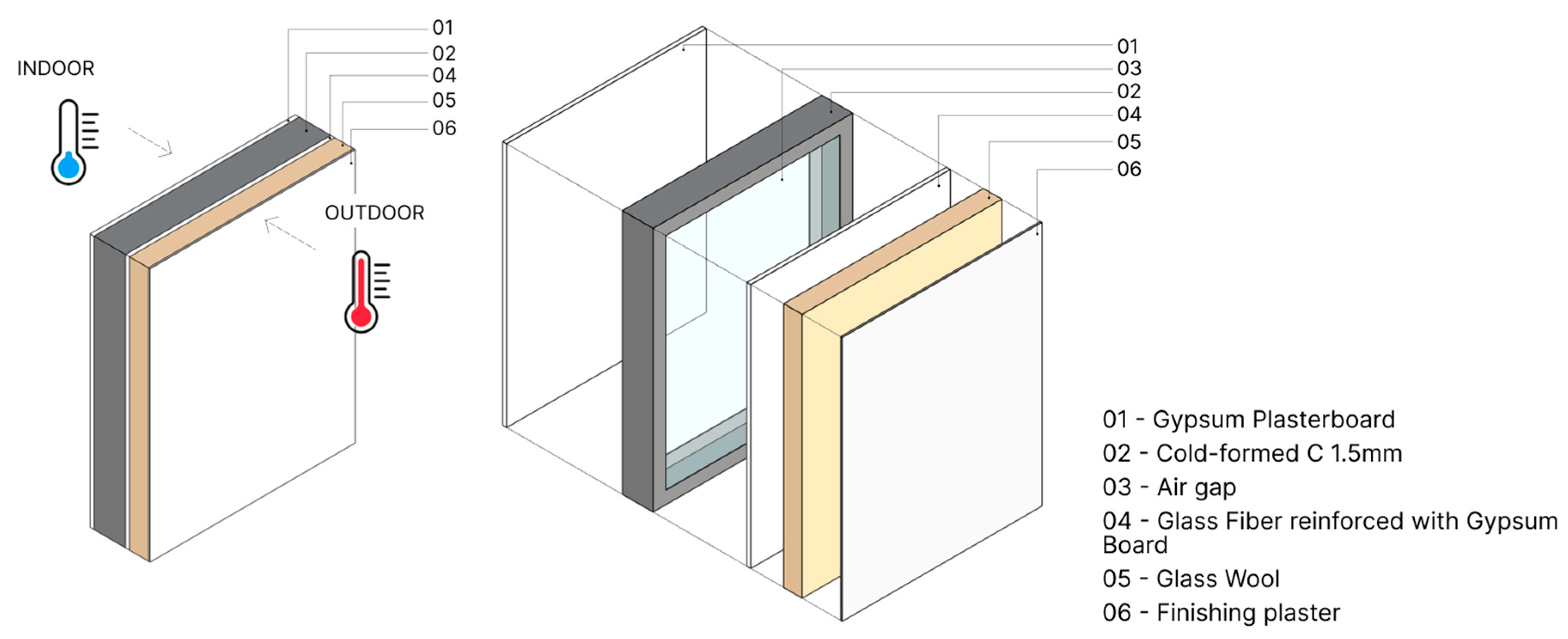
The wall panel used is a commercial LSF solution with the composition described in Figure 1. The thermophysical properties of the materials and the dimensions of the different layers are detailed in Table 1.

2.2. Methods

Methodology and Procedures

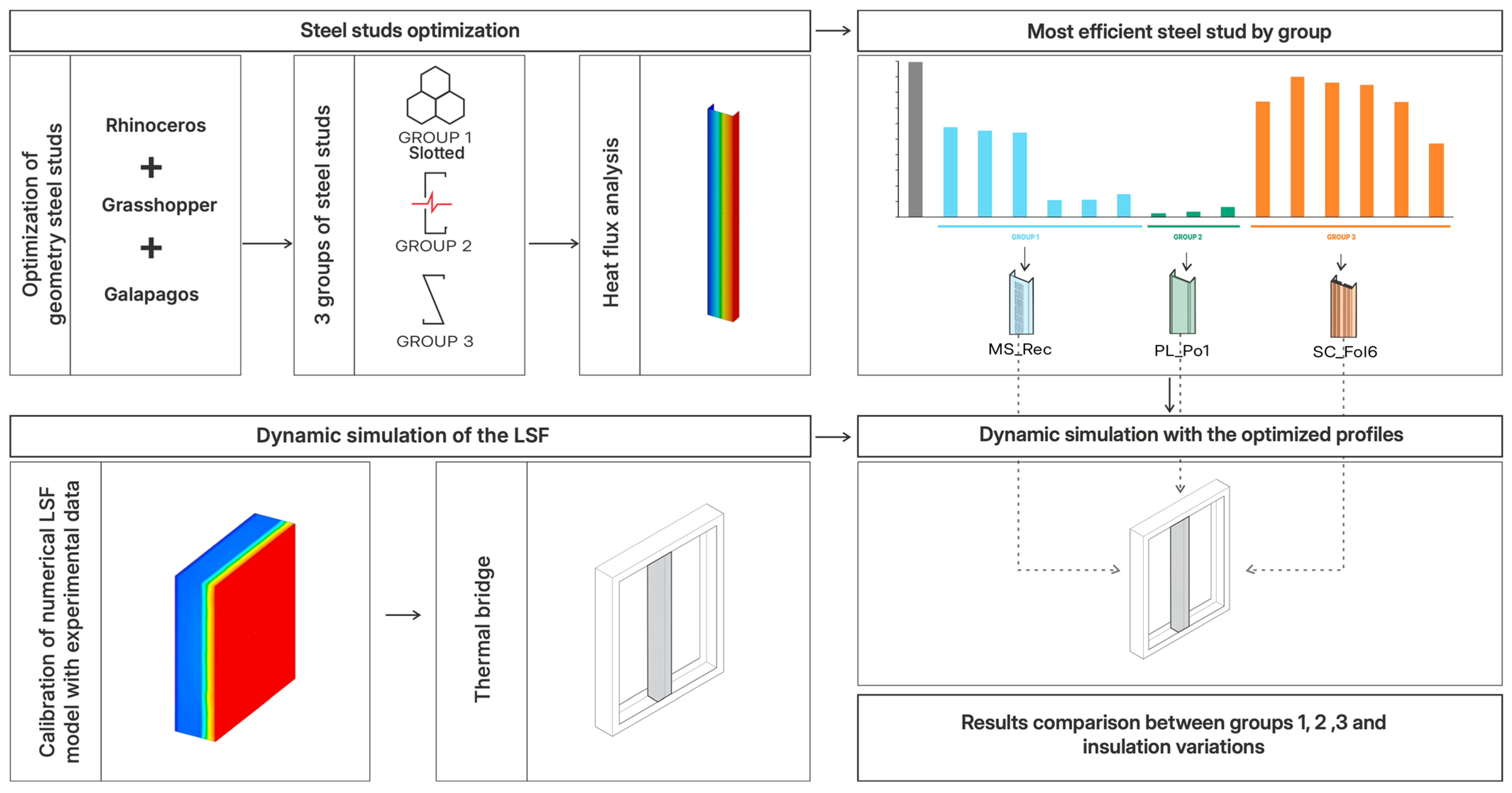
The methodology combines a workflow that integrates geometric optimization, dynamic simulations and numerical analysis to optimize the thermal performance of the steel studs. Figure 2 illustrates the methodology that was implemented for the optimization and dynamic analysis of steel profiles used in Light Steel Frame (LSF) systems. The workflow can be divided into two main stages: the geometric optimization of the steel profiles and the dynamic simulation of the LSF system.
In the first stage, the steel profiles were divided into three main groups, each with different characteristics. Group 1 consists of profiles with slotted geometries designed to reduce thermal conductivity. Group 2 includes profiles interrupted by elements of lower conductivity, with the aim of minimizing heat flow between surfaces. Group 3 includes profiles with variations in the geometry of the section. More information about the groups and their details is provided in the following sections.
After classification, the steel profiles of Group 1 were optimized using Rhinoceros software (version 8.13), the Grasshopper plugin and the Galapagos optimization tool. All groups were then subjected to heat flux analysis. The 15 models were evaluated and compared to a reference-steel stud solution with dimensions of 100 × 40 × 800 mm (width, height, and length, respectively) and a thickness of 1.5 mm. The most efficient profiles were then identified: MS_Rec in Group 1; PL_Po1 in Group 2; and SC_Fo16 in Group 3.
In the second stage, the thermal performance of the LSF single-layer wall system was simulated. The numerical model was calibrated using experimental data from a hot box testing apparatus, as described by Figueiredo et al. [40]. The simulation, conducted in Ansys Mechanical, replicated the experimental boundary conditions, allowing for a detailed analysis of the thermal performance of the construction system (see Figure 3).
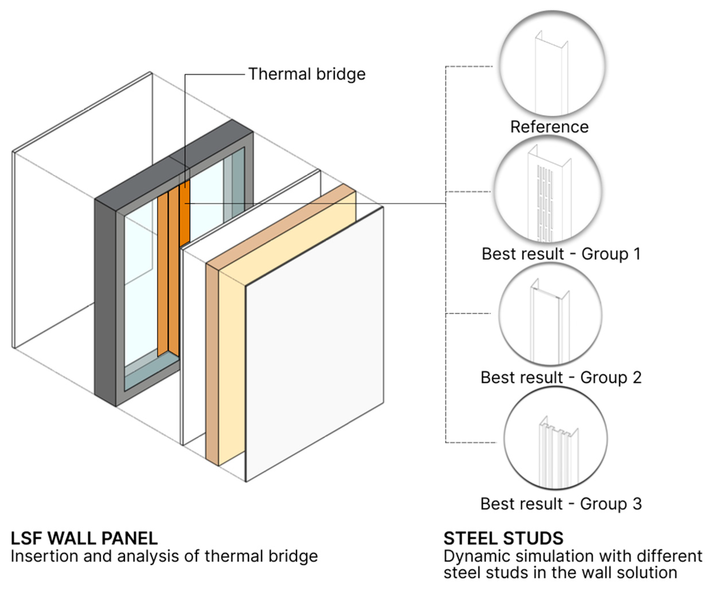
Subsequently, the most efficient profiles previously identified in each group were incorporated into the wall panel of the system (see Figure 4) and simulated under dynamic conditions, evaluating variations in thermal insulation and geometry efficiency.
The simulations also include the analysis of the impact of an external insulation layer and the variation of its thickness (0—without, 20, 40 and 60 mm) on the performance of the wall. The results allowed a detailed comparison between the groups, highlighting the best solutions for thermal optimization.

2.3. Parametric Analysis Definition

For the variations in steel studs, the basic principles of the geometry of the steel studs were considered with respect to the structural integrity of the cross-section. To ensure mechanical strength, a margin of 25 mm around the surface of the web and a 20% limitation in the slotted area were maintained [34].
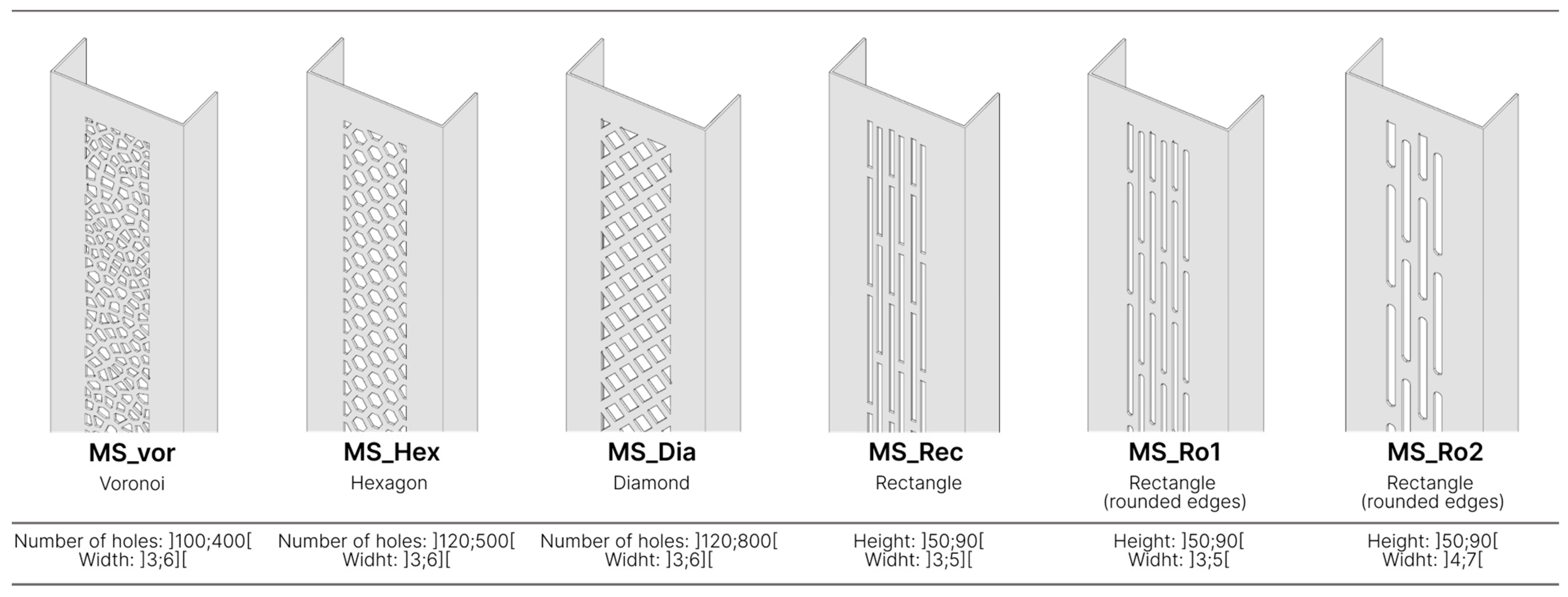
The initial group of models comprised the generation of different web meshes for the steel studs, incorporating various slot patterns. Six models were proposed and analyzed, including variations in geometry, gap dimensions, angles, and edge types. These models were developed using computational optimization techniques in Grasshopper software (version 1.0), with modeling assistance provided by Rhinoceros software (version 8.13).
The visual programming code in Grasshopper employed the Galapagos component to perform optimization through a genetic algorithm. The code was designed to parameterize the web geometry so that each solution, despite its differences, maintained the same solid material volume (97 cm3), which represents 80% of the volume of a reference web section without holes. This approach ensured comparability between results. The proposed types of slots are illustrated in Figure 5. The MS_Vor, MS_Hex and MS_Dia models were optimized based on the number of holes in the web section, while the MS_Rec, MS_Ro1 and MS_Ro2 models were optimized based on the size of the rectangular slots.
The simulation was performed on a computer equipped with two CPUs with 20 cores and 40 threads each, 128 GB of RAM, a 1 TB solid-state drive, and an RTX A4000 graphics card with 16 GB of memory.
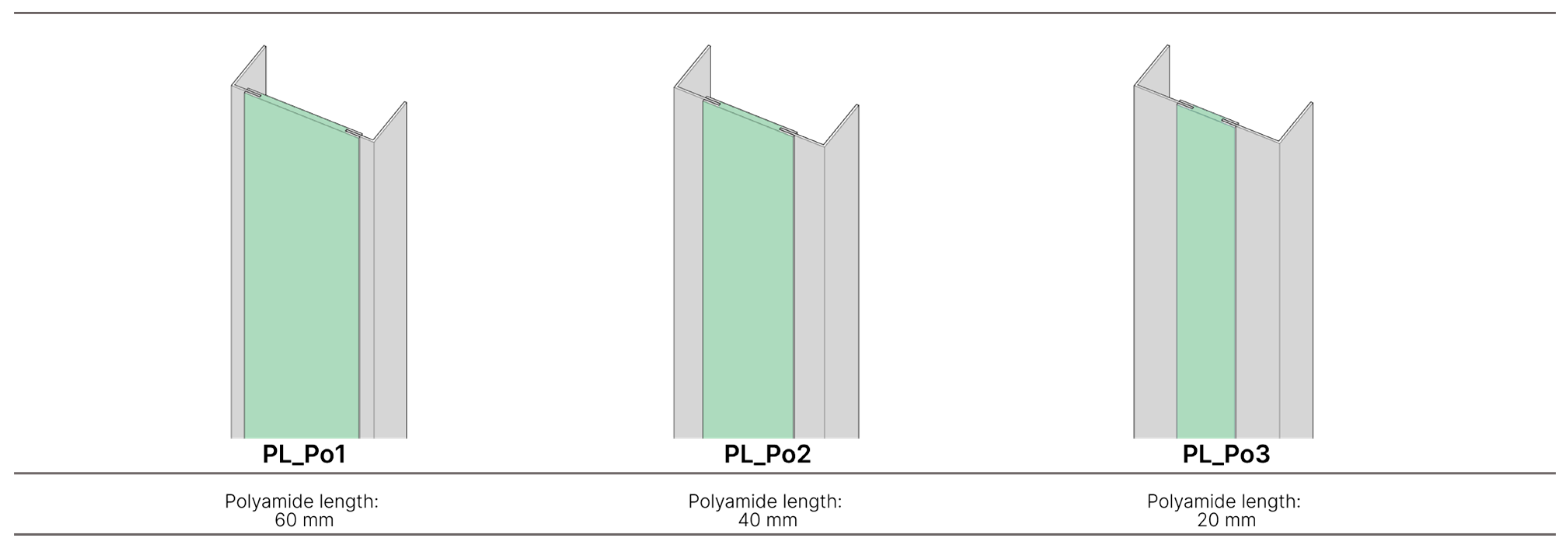
The second group of models was designed to mitigate the thermal bridge effect of the steel studs by incorporating a less-conductive material into the web section. Specifically, a rigid polyamide element was introduced in the middle of the web, oriented vertically. In order to determine whether the width of the polyamide member would influence the heat flux, three models were proposed, each featuring a different width for the added material (60 mm, 40 mm, and 20 mm) (see Figure 6).
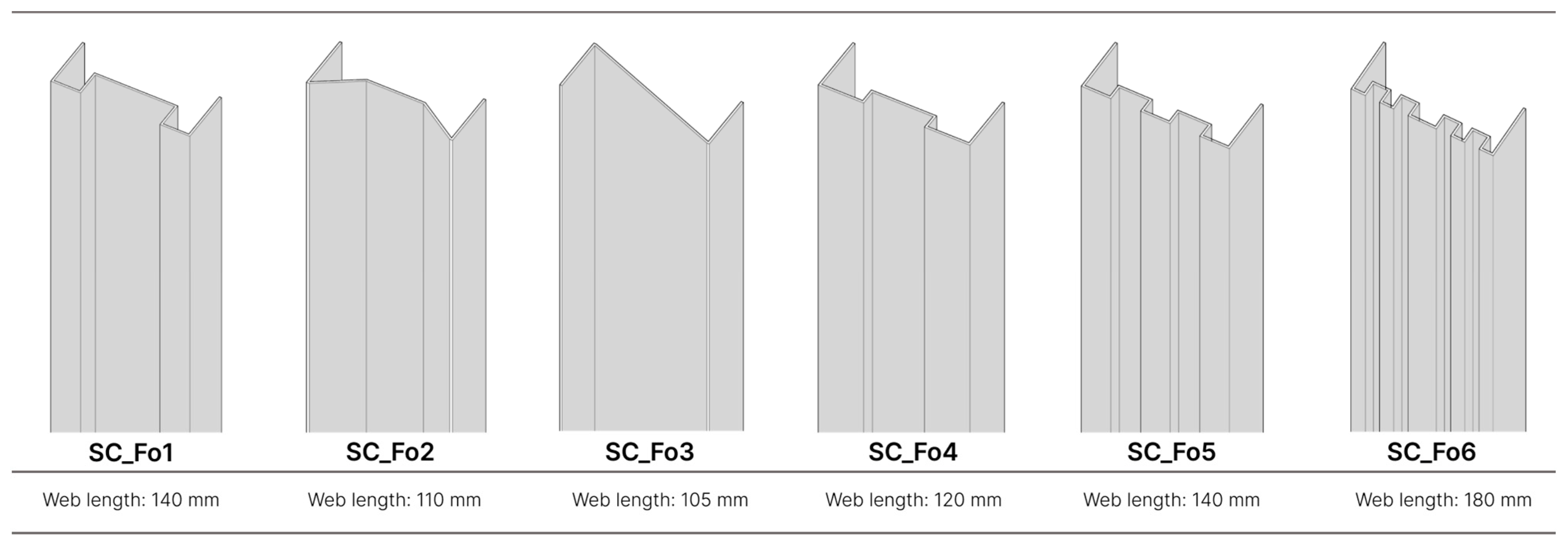
The third group involved modifying the shape of the web section by introducing simple folding geometries. This approach aimed to increase the length of the heat flux path along the web cross-section of the steel stud, therefore improving thermal performance. Six distinct folding configurations were created, as shown in Figure 7.
The heat flux of the steel studs from the three groups was calculated using simulations performed in Ansys software (version R1 2024). The boundary conditions for the Finite Element Method (FEM) simulation were defined by applying a temperature difference (ΔT) of 10 °C (20 °C and 30 °C on opposing surfaces) to the flanges, while all other surfaces were set as adiabatic.

2.4. Numerical Simulation of LSF System

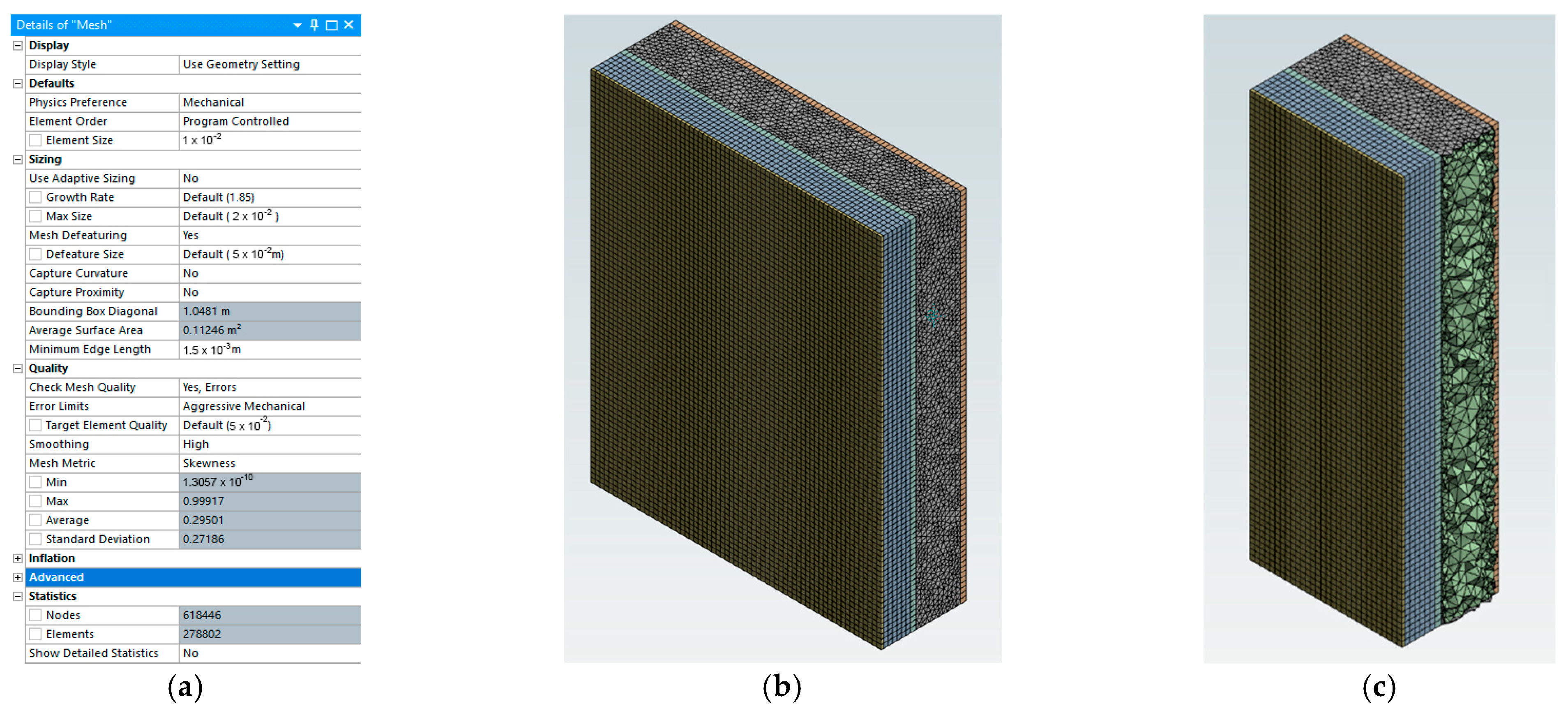
The Finite Element Method (FEM) simulation was performed using Ansys Mechanical software version R1 2024. The mesh model was discretized using the Automatic (Primemesh) method, with the mesh characteristics presented in Figure 8. The same configuration used for the reference model was consistently applied across all other simulations in the FEM analysis.
For the simulation in Ansys, the Transient Thermal module was used with the following boundary conditions:
  • Side 1 (simulating indoor conditions) temperature: 8 °C for 480 min, increasing by 2 °C every 480 min until reaching 30 °C.
  • Side 2 (simulating outdoor conditions) temperature: 18 °C for 480 min, increasing by 2 °C every 480 min until 40 °C is reached.
The other boundaries were all set as adiabatic. The required thermophysical properties of the materials were configured using the data presented in Table 1.

3. Results

3.1. Simulation of Steel Studs

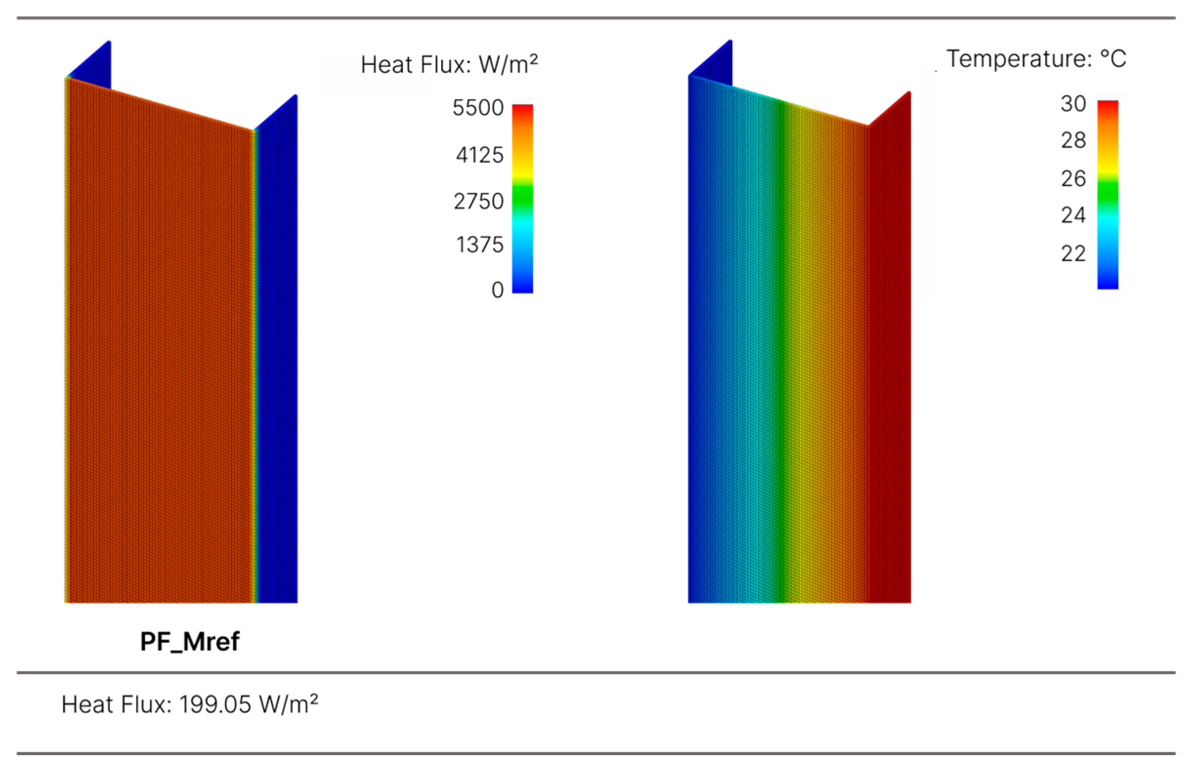
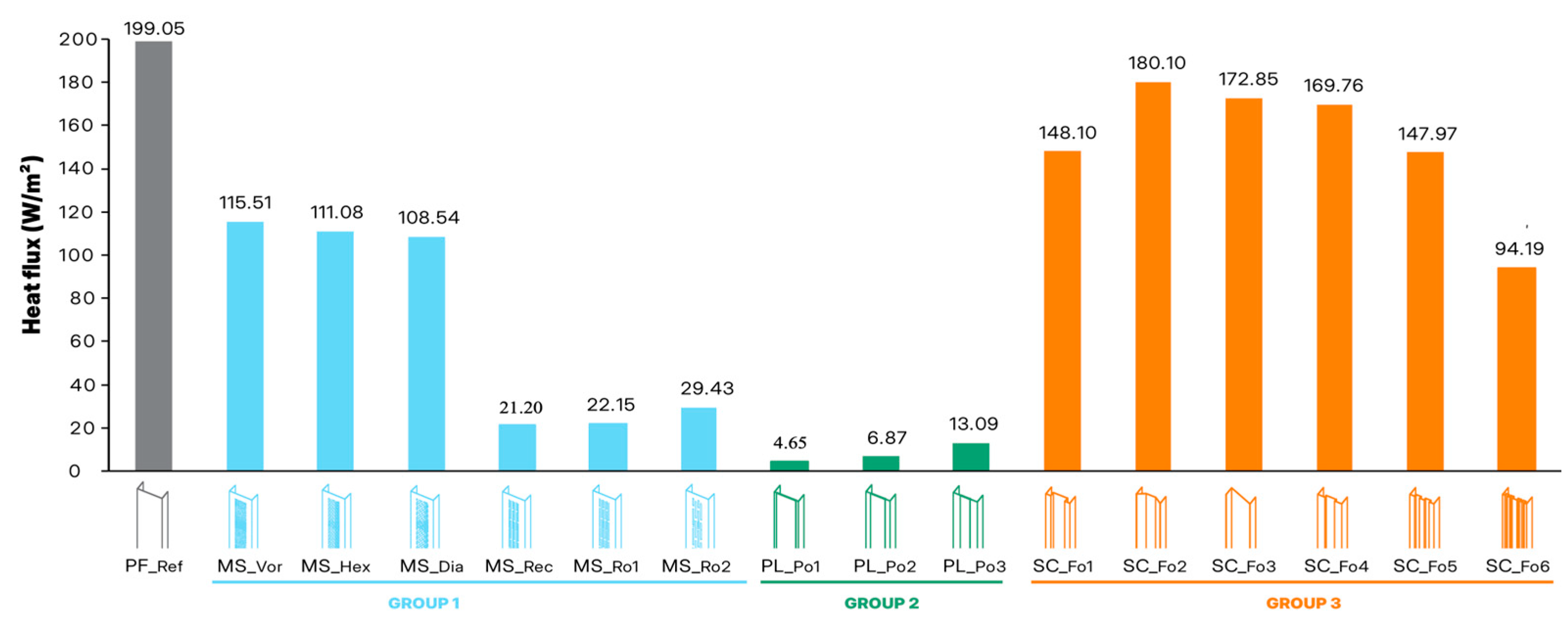
This section presents the analysis of the simulation results for the steel studs featuring different geometric alternatives across the 3 groups. For comparison purposes, the first steel stud simulated was a standard commercial solution, serving as the reference model (PF_Mref), without slots (see Figure 9). This reference model presented a total heat flux of 199.05 W/m2.
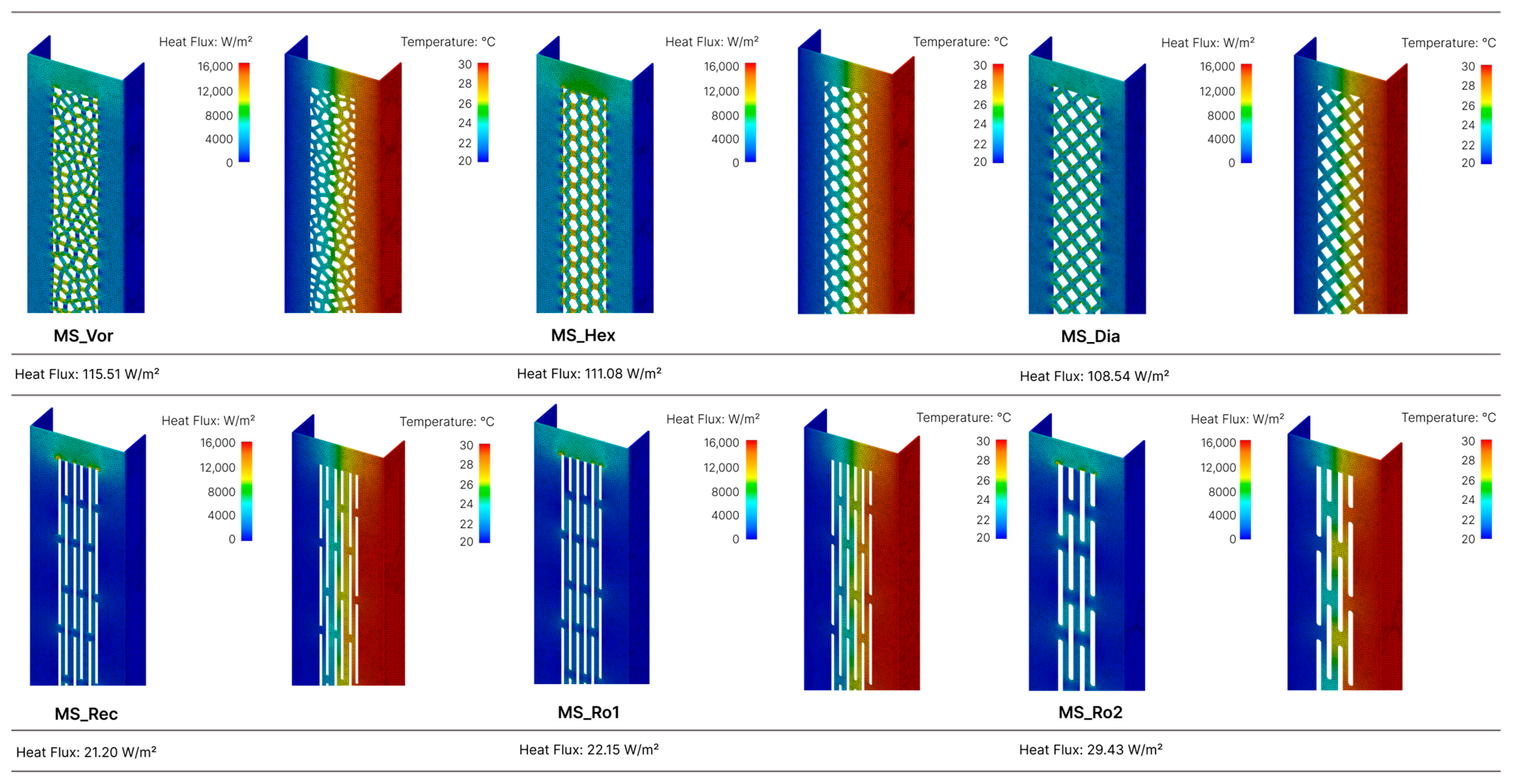
As detailed in the methodology section, the first group with six models, features distinct slot patterns derived through optimization. Among these models, a significant reduction in heat flux is observed compared to the reference model. Despite the 20% reduction in material volume, the heat flux decreases by up to 90%.
The highest heat flux within Group 1 is exhibited by the MS_Vor model, which has an irregular mesh and edges with a geometry based on Voronoi. This model shows a heat flux of 115.51 W/m2, representing a 42% reduction compared to the reference-steel stud. Conversely, the optimal result in this category is achieved by the MS_Rec model, which incorporates intercalated rectangular gaps with straight edges, resulting in a heat flux of just 21.20 W/m2. Figure 10 provides a graphical representation of the six models simulated.
The incorporation of a material to partially replace the web section of the steel stud proved to be highly effective, with the models in Group 2 delivering the most favorable results. The PL_Po1 model, comprising a 60 mm wide rigid polyamide component, achieved the best performance among all analyzed options, with a heat flux of just 4.65 W/m2. This represents a reduction of approximately 98% in heat flux compared to the reference model. The PL_Po3, with a 20 mm wide polyamide component, exhibited a heat flux of 13.09 W/m2, the highest within Group 2. However, it still ranked as the third-best result overall, achieving a nearly 93% reduction in heat flux. Figure 11 illustrates the simulated models.
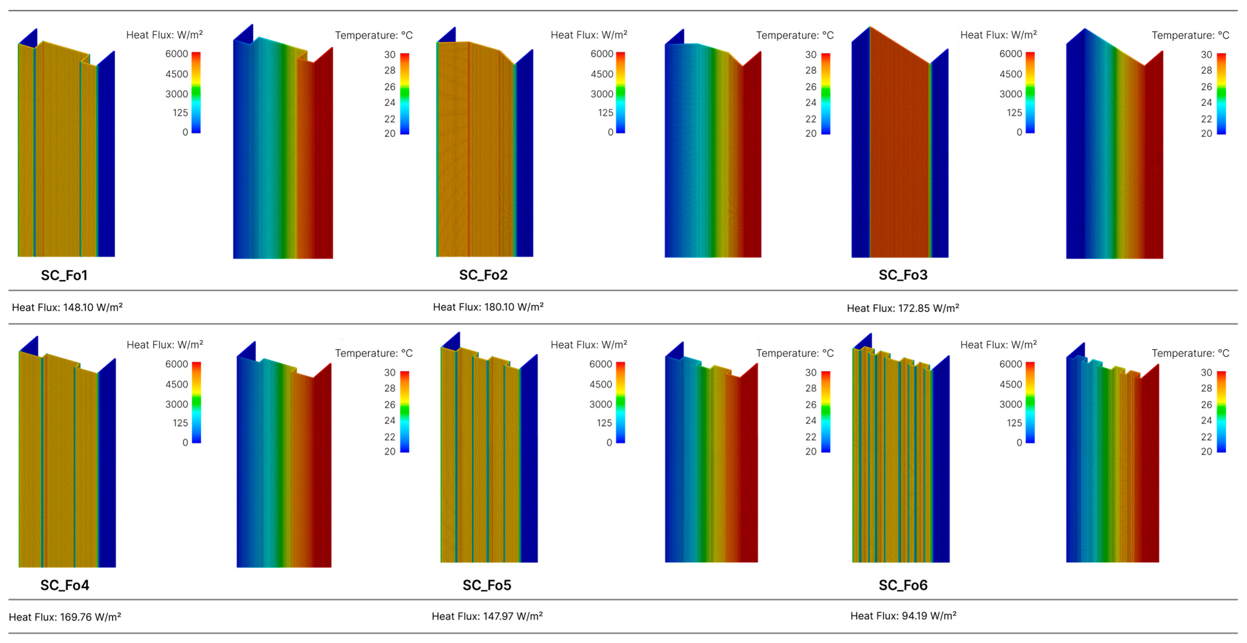
The component models of Group 3, featuring variations in folding shapes, revealed heat flux reductions of up to 53% compared to the reference model. These results are particularly noteworthy, as they are derived from modifications to the reference model that do not incorporate slots and/or the insertion of different materials. The best-performing model in this group is the SC_Fo6, which has the largest number of folds and presents a heat flux of 94.19 W/m2. In contrast, the least favorable outcome is the SC_Fo2 model, with a heat flux of 180.01 W/m2, closely resembling the result of the reference model. The results of the simulations are presented in Figure 12.
The simulation results demonstrate that optimizing LSF steel studs can lead to significant improvements in the thermal performance of the system. However, certain aspects, such as a coupled study of mechanical and thermal performance, remain to be addressed to ensure the feasibility of these designs. These considerations fall outside the scope of the current analysis.
The modified web section simulations were compared to the reference case, with results organized by groups according to the methodology outlined earlier. Figure 13 shows the results of all simulated steel studs and clearly illustrates that all proposed models achieved heat flux values lower than the reference model. Based on the analysis, the best-performing models from each group were selected for further evaluation.

3.2. Numerical Model Calibration

A numerical model was developed using Ansys software to simulate an LSF wall panel based on hotbox testing data conducted by Figueiredo et al. [40]. For the computational simulation, the thermos-physical properties of the materials were defined according to the supplier’s specifications.
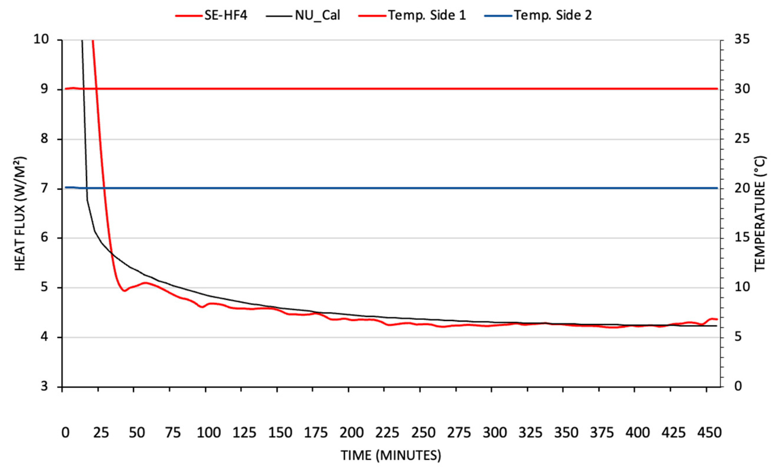
The heat flux of the LSF system was calibrated considering a temperature difference of 10 °C between the surfaces of the wall panel. Figure 14 illustrates the results of the Finite Element Method (FEM) simulation, presenting both the experimental data (EXP) and the calibrated numerical model (NU_Cal).
The graph shows that the initial differences between the experimental heat flux (SE-HF4) and the numerical model (NU_Cal) gradually adjust over time and may be attributed to dynamic boundary conditions and the transient behavior of the panel materials. After approximately 150 min, the heat flux stabilizes at around 4.5 W/m2 for both curves, approximately representing the system’s steady-state condition. During this period, the applied temperature difference (30 °C and 20 °C) remains constant, reinforcing the uniformity of the boundary conditions.
Analyzing both the experimental and simulated curves, slight differences were observed prior to reaching heat flux equilibrium. However, once equilibrium was achieved, an excellent agreement between the two curves was noted.

3.3. Simulation Results with Optimized Steel Studs for Different Insulation Thickness

Based on the results from Section 3.1, the most effective solutions were identified and selected for thermal evaluation. The LSF system was then comprehensively simulated, incorporating the optimized components and varying the insulation thickness to assess their impact on thermal performance. Figure 15 shows the heat flux results obtained from the simulation of the wall solution containing the following models: NU_Cal (calibrated numerical model), PF_Mref (reference model), MS_Rec (Group 1), PL_Po1 (Group 2), and SC_Fo6 (Group 3). The temperature range of 20 °C to 30 °C was chosen for the analysis, as it reflects the thermal characteristics of the materials at an average temperature of 25 °C.
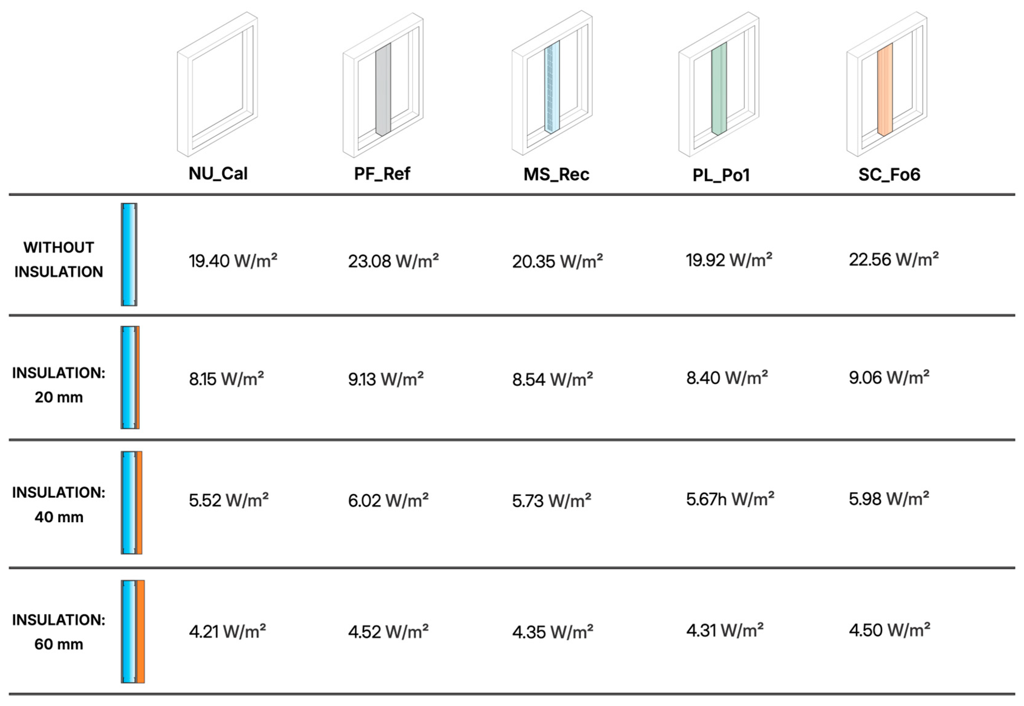
The insertion of a steel stud, representing a thermal bridge at the center of the LSF wall panel, resulted in an increase in heat flux ranging from 0.31 W/m2 to 3.69 W/m2 when comparing the calibrated model (NU_Cal) with the reference model (PF_Ref). However, when the modified steel studs were introduced to mitigate the thermal bridge, a reduction in heat flux was observed across all analyzed options. The most notable reductions occurred when comparing PF_Ref with the modified steel studs without insulation. The PL_Po1 model achieved the greatest reduction at 3.17 W/m2, followed by MS_Rec with 2.73 W/m2. In contrast, SC_Fo6 showed lower reductions, consistently below 0.10 W/m2 across all insulated scenarios (20 mm, 40 mm, and 60 mm).
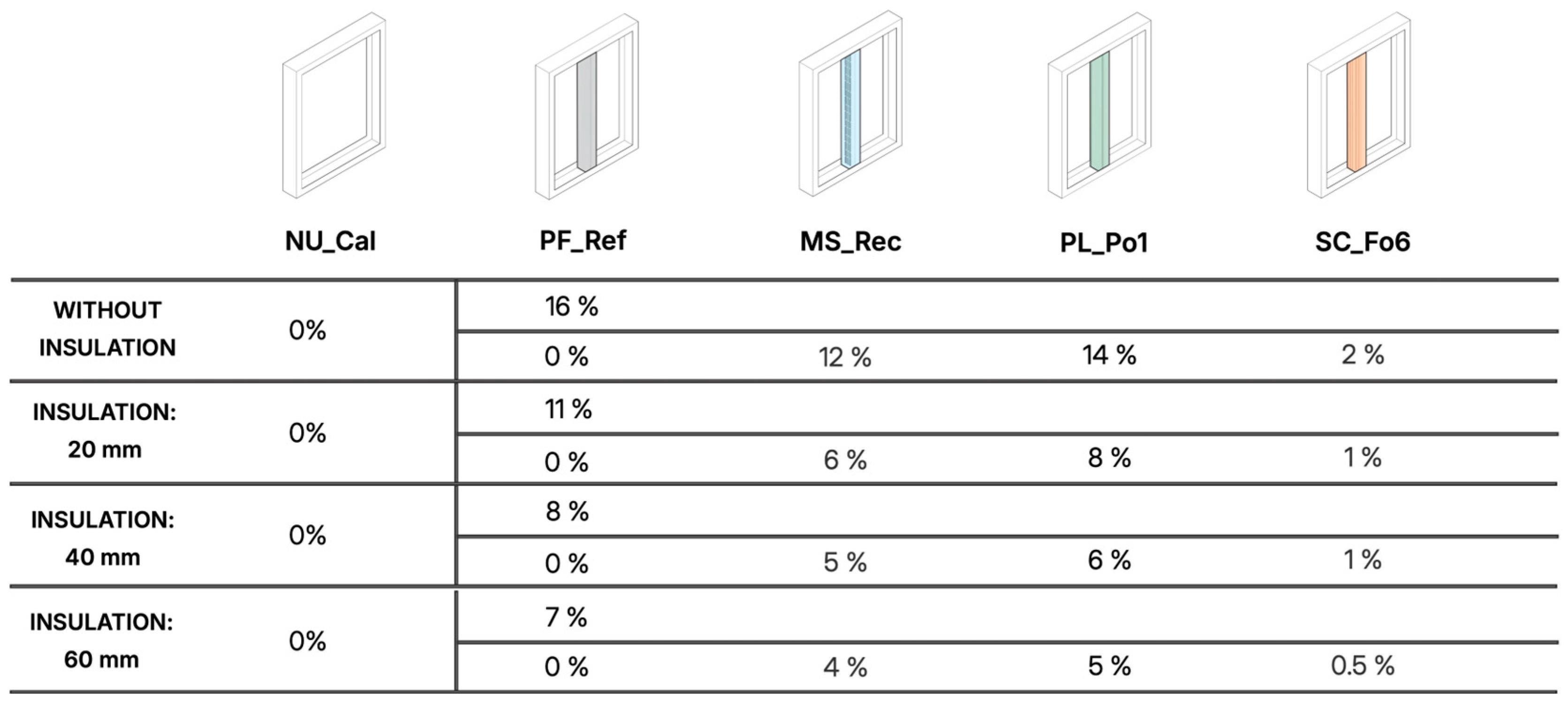
Figure 16 shows the percentage increase in heat flux for each scenario. The results indicate that PL_Po1 is the most promising model, with a 14% decrease in heat flux. In all cases, it was the model with a higher reduction in thermal bridge. The MS_Rec model also shows a significant performance with reductions ranging from 4% to 12% compared to PF_Ref.
The results presented in Figure 16 highlight the effectiveness of the modified steel profile solutions in reducing heat flux. The PL_Po1 and MS_Rec models demonstrated the best performance, achieving reductions of up to 14% and 12%, respectively, compared to the reference model PF_Ref. These findings align with the strategies proposed by Höglund et al. [37], which stated that the insertion of slots in steel profiles can be an effective measure to mitigate thermal bridging, reducing thermal transmission by up to 16%. Furthermore, the simulated values are also consistent with the data presented by Martins et al. [12], who emphasized the importance of combining geometric modifications with insulating materials to optimize thermal performance. Studies conducted in Finland and Sweden by Nieminen et al. [41] demonstrated that the equivalent thermal conductivity of perforated profiles ranges from 5 to 10 W/m2K, depending on factors such as the design and dimensions of the slots, the insulating material properties filling the spaces, and the dimensions of the solid steel segments between the slots.
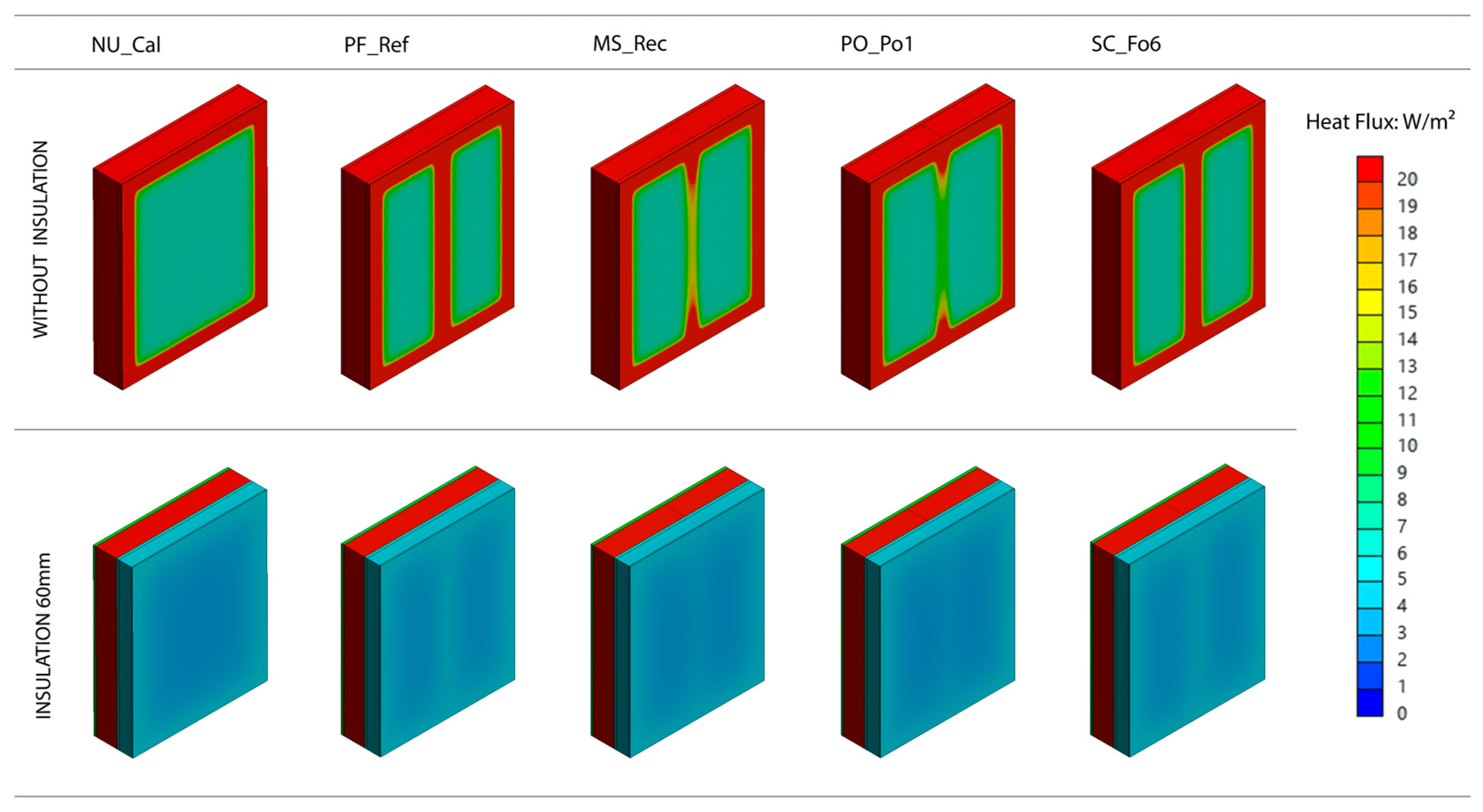
Figure 17 shows the distribution of heat flux (W/m2) in the panel configurations, comparing the scenarios without insulation and with 60 mm of external insulation layer (the maximum thickness analyzed). Without insulation, the heat flux is obviously more intense and concentrated in the areas near the steel profiles. The insulation layer significantly reduces the heat flux and promotes greater thermal uniformity.
The simulation results for the LSF systems with modified steel studs indicate a consistent reduction in heat flux across all cases. The findings highlight the most effective steel studs from Groups 1 and 2, demonstrating significant potential for reducing the heat flux of the LSF wall panel. The largest reductions were observed in models without insulation or with thinner insulation layers, in which the impact of thermal bridges is obviously more relevant.

4. Conclusions

The objective of this study was to evaluate which geometric modifications and solutions of steel studs, particularly in the web section, could provide the most favorable results for the thermal performance of LSF wall panels. The optimization results show that the most effective approaches for t reducing heat flux involve web slotting and the incorporation of less-conductive materials in the web section to mitigate thermal bridging.
The main findings from this parametric analysis are as follows:
  • The addition of a steel stud significantly increases heat flux, adding 3.68 W/m2 to the heat flux of the wall panel without insulation, highlighting the opportunity to modify the web section to reduce thermal bridging.
  • A weight reduction in the steel studs can be an effective strategy for the mitigation of heat flux and enhancing the thermal performance of the system. In this study, the volume of the web was reduced by 20% in Group 1.
  • Modifying the web section, as in Group 3, results in a significant reduction in the heat flux (0.52 W/m2 to 0.02 W/m2), although less than with the introduction of slots and/or the use of a less-conductive material.
  • The shape of the slots influences heat flux: rectangular shapes, aligned vertically, increase the path of heat flux through the metal, effectively improving thermal performance.
  • The most effective strategy for enhancing the thermal performance of the steel studs was the use of a less-conductive material, such as polyamide, within the web section (Group 2). This corresponds to a reduction in the heat flux between 3.16 W/m2 and 0.21 W/m2 between the different types of insulation.
  • As insulation thickness increases, the impact of the modified steel studs becomes less pronounced, with the potential for reduction diminishing and becoming less evident in highly insulated configurations.
Further studies should focus on analyzing the structural performance of the proposed steel stud solutions from the 3 groups in conjunction with their thermal performance. Additionally, a Life Cycle Assessment (LCA) is necessary, as some solutions, such as slotting and material replacement, may have an impact on the use of steel. Future works should also include further technical and economical characterization of the optimized solutions, including evaluation of surface temperature factors (fRsi) and the risk of condensation at connection zones, as well as the calculation of the return-on-investment period (payback). These analyses will provide a more comprehensive understanding of the practical and economic feasibility of the proposed modifications.

Author Contributions

Conceptualization, M.L. and T.A.S.; methodology, M.L. and A.F.; software, M.L.; validation, A.F., R.V. and R.M.S.F.A.; writing—original draft preparation, T.A.S.; writing—review and editing, M.L., A.F., R.V. and R.M.S.F.A.; visualization, M.L. and T.A.S.; supervision, A.F., R.V. and R.M.S.F.A.; project administration, R.V.; funding acquisition, R.V. All authors have read and agreed to the published version of the manuscript.

Funding

This research was supported by the Foundation for Science and Technology (FCT)–Ref. 2022.12799.BD, by the Research Centre for Risks and Sustainability in Construction (RISCO), Universidade de Aveiro, Portugal, and was also developed in the scope of the Project “Agenda ILLIANCE” [C644919832-00000035|Project nº 46], financed by PRR–Plano de Recuperação e Resiliência under the Next Generation EU from the European Union.

Data Availability Statement

The raw data supporting the conclusions of this article will be made available by the authors upon request.

Conflicts of Interest

The authors declare no conflicts of interest.

References

  1. European Commission. Energy Efficiency in Buildings; European Commission: Brussels, Belgium, 2020. [Google Scholar]
  2. The Official Journal of the European Union. Directive 8(EU) 2018/844 of the European Parliament and of the Council on the Energy Performance of Buildings and on Energy Efficiency; The Official Journal of the European Union: Brussels, Belgium, 2018. [Google Scholar]
  3. The Official Journal of the European Union. Directive (EU) 2018/2001 of the European Parliament and of the Council on the Promotion of the Use of Energy from Renewable Sources; The Official Journal of the European Union: Brussels, Belgium, 2018. [Google Scholar]
  4. Figueiredo, A.; Almeida, R.M.S.F.; Vicente, R.; Ferreira, V.M. Impact of Heating Strategies towards Energy-Efficient Buildings. Energy Build. 2024, 315, 114287. [Google Scholar] [CrossRef]
  5. Sengupta, A.; Douaa, A.A.; Kazanci, O.B.; Shinoda, J.; Breesch, H.; Steeman, M. Building and System Design’s Impact on Thermal Resilience to Overheating during Heatwaves: An Uncertainty and Sensitivity Analysis. Build. Environ. 2024, 265, 112031. [Google Scholar] [CrossRef]
  6. Figueiredo, A.; Figueira, J.; Vicente, R.; Maio, R. Thermal Comfort and Energy Performance: Sensitivity Analysis to Apply the Passive House Concept to the Portuguese Climate. Build. Environ. 2016, 103, 276–288. [Google Scholar] [CrossRef]
  7. Gonçalves, M.; Figueiredo, A.; Almeida, R.M.S.F.; Vicente, R.; Samagaio, A.; Kośny, J. Thermal Performance Evaluation of a Light Steel Framing Building with Macroencapsulated Phase Change Materials in a Mediterranean Climate. Energy Build. 2024, 323, 114837. [Google Scholar] [CrossRef]
  8. Roque, E.; Vicente, R.; Almeida, R.M.S.F. Opportunities of Light Steel Framing towards Thermal Comfort in Southern European Climates: Long-Term Monitoring and Comparison with the Heavyweight Construction. Build. Environ. 2021, 200, 107937. [Google Scholar] [CrossRef]
  9. Roque, E.; Vicente, R.; Almeida, R.M.S.F.; Ferreira, V.M. Energy Consumption in Intermittently Heated Residential Buildings: Light Steel Framing vs Hollow Brick Masonry Constructive System. J. Build. Eng. 2021, 43, 103024. [Google Scholar] [CrossRef]
  10. Roque, E.; Vicente, R.; Almeida, R.M.S.F.; Ferreira, V.M. The Impact of Thermal Inertia on the Indoor Thermal Environment of Light Steel Framing Constructions. Energies 2022, 15, 3061. [Google Scholar] [CrossRef]
  11. Soares, N.; Santos, P.; Gervásio, H.; Costa, J.J.; Silva, L.S. Energy Efficiency and Thermal Performance of Lightweight Steel-Framed (LSF) Construction: A Review. Renew. Sustain. Energy Rev. 2017, 78, 194–209. [Google Scholar] [CrossRef]
  12. Martins, C.; Santos, P.; Silva, L.S. Lightweight Steel-Framed Thermal Bridges Mitigation Strategies: A Parametric Study. J. Build. Phys. 2016, 39, 342–372. [Google Scholar] [CrossRef]
  13. Ge, H.; Baba, F. Dynamic Effect of Thermal Bridges on the Energy Performance of a Low-Rise Residential Building. Energy Build. 2015, 105, 106–118. [Google Scholar] [CrossRef]
  14. Sun, K.; Zheng, C.; Wang, X. Thermal Performance and Thermal Transmittance Prediction of Novel Light-Gauge Steel-Framed Straw Walls. J. Build. Eng. 2023, 67, 105973. [Google Scholar] [CrossRef]
  15. Santos, P.; Lopes, P.; Abrantes, D. Thermal Performance of Load-Bearing, Lightweight, Steel-Framed Partition Walls Using Thermal Break Strips: A Parametric Study. Energies 2022, 15, 9271. [Google Scholar] [CrossRef]
  16. Tadeu, A.; Simões, I.; Simões, N.; Prata, J. Simulation of Dynamic Linear Thermal Bridges Using a Boundary Element Method Model in the Frequency Domain. Energy Build. 2011, 43, 3685–3695. [Google Scholar] [CrossRef]
  17. Larbi, A.B. Statistical Modelling of Heat Transfer for Thermal Bridges of Buildings. Energy Build. 2005, 37, 945–951. [Google Scholar] [CrossRef]
  18. Gorgolewski, M. Developing a Simplified Method of Calculating U-Values in Light Steel Framing. Build. Environ. 2007, 42, 230–236. [Google Scholar] [CrossRef]
  19. Zalewski, L.; Lassue, S.; Rousse, D.; Boukhalfa, K. Experimental and Numerical Characterization of Thermal Bridges in Prefabricated Building Walls. Energy Convers. Manag. 2010, 51, 2869–2877. [Google Scholar] [CrossRef]
  20. Atsonios, I.A.; Mandilaras, I.D.; Kontogeorgos, D.A.; Founti, M.A. Two New Methods for the In-Situ Measurement of the Overall Thermal Transmittance of Cold Frame Lightweight Steel-Framed Walls. Energy Build. 2018, 170, 183–194. [Google Scholar] [CrossRef]
  21. Stromberg, J. Development of Dry Composite Construction Systems Based on Seel in Residential Applications: Final Report; Office for Official Publications of the European Communities (EUR-OP): Luxembourg, 2002; ISBN 9289439467. [Google Scholar]
  22. Santos, P. Energy Efficiency of Lightweight Steel-Framed Buildings. In Energy Efficient Buildings; InTech: Shinjuku, Japan, 2017. [Google Scholar]
  23. Baskar, R.; Duraimurugan, K.S.K. Structural Performance of Cold-Formed Steel Channel Joist with Web Openings Subjected to Bending. Matéria 2024, 29, 839. [Google Scholar] [CrossRef]
  24. Pham, N.H. Investigation of Web Hole Effects on Capacities of Cold-Formed Steel Channel Members; Lecture Notes in Civil Engineering; Springer Science and Business Media Deutschland GmbH: Berlin, Germany, 2023; Volume 235, pp. 161–175. [Google Scholar]
  25. Francis, R.; Shabhari, A.; Chandrasekar, D.; Jeyapragasam, V.V.K. Investigation of Local Buckling Behavior of Web Perforated Plain Channel Stub Columns. J. Constr. Steel Res. 2024, 222, 108978. [Google Scholar] [CrossRef]
  26. Wang, W.; Roy, K.; Fang, Z.; Ananthi, G.B.G.; Lim, J.B.P. Web Crippling Behaviour of Cold-Formed Steel Channels with Elongated Un-Stiffened and Edge-Stiffened Web Holes under End-Two-Flange Loading Condition. Thin-Walled Struct. 2024, 195. [Google Scholar] [CrossRef]
  27. Živaljević, V.; Jovanović, Đ.; Kovačević, D.; Džolev, I. The Influence of Web Holes on the Behaviour of Cold-Formed Steel Members: A Review. Buildings 2022, 12, 1091. [Google Scholar] [CrossRef]
  28. Zhao, J.; He, J.; Chen, B.; Zhang, W.; Yu, S. Test and Direct Strength Method on Slotted Perforated Cold-Formed Steel Channels Subjected to Eccentric Compression. Eng. Struct. 2023, 285. [Google Scholar] [CrossRef]
  29. He, Z.; Jian, Y.; Zhou, X.; Jin, S. Local-Distortional Interactive Behavior and Design of Cold-Formed Steel C-Sections with & without Slotted Holes. J. Build. Eng. 2023, 79, 107812. [Google Scholar] [CrossRef]
  30. Pham, N.H. Numerical Investigation of Cold-Rolled Aluminium Alloy Stub Columns with Perforations Undergoing Local Buckling. Iran. J. Sci. Technol.—Trans. Civ. Eng. 2023, 47, 3453–3463. [Google Scholar] [CrossRef]
  31. Paul, B.; Roy, K.; Ji, Y.; Fang, Z.; Sivaji, V.; Lim, J.B.P. Moment Capacity of Perforated Cold-Formed Aluminium Channels–Tests, Analysis, and Design. Thin-Walled Struct. 2024, 204. [Google Scholar] [CrossRef]
  32. Vu, Q.A.; Pham, N.H.; Thinh, V.T.; Nguyen, N.T. Overview on Research on the Strength and Behavior of Cold-Formed Steel Members with Perforations. In Proceedings of the E3S Web of Conferences, Nantes, France, 28–30 August 2024; EDP Sciences: Les Ulis, France, 2024; Volume 533. [Google Scholar]
  33. Santos, P.; Lopes, P.; Abrantes, D. Thermal Performance of Lightweight Steel Framed Facade Walls Using Thermal Break Strips and ETICS: A Parametric Study. Energies 2023, 16, 1699. [Google Scholar] [CrossRef]
  34. Alekperov, R.; Aksenov, I. Decrease of Cold-Formed Slotted Studs Heat Conductivity by Slots Shape Modification. In Proceedings of the E3S Web of Conferences, Bucharest, Romania, 26–29 May 2019; EDP Sciences: Les Ulis, France, 2019; Volume 97. [Google Scholar]
  35. Garifullin, M.; Sinelnikov, A.; Bronzova, M.; Kovacic, B.; Kamnik, R. Buckling Behavior of Cold-Formed Studs with Thermal Perforations. In MATEC Web of Conferences; EDP Sciences: Les Ulis, France, 2016. [Google Scholar]
  36. Blomberg, T.R.; Claesson, J. Heat Transmission Through Walls with Slotted Steel Studs; American Society of Heating, Refrigerating and Air-Conditioning Engineers (ASHRAE): Clearwater Beach, FL, USA, 1998; pp. 621–628. [Google Scholar]
  37. Höglund, T.; Burstrand, H. Slotted Steel Studs to Reduce Thermal Bridges in Insulated Walls. Thin-Walled Struct. 1998, 32, 81–109. [Google Scholar] [CrossRef]
  38. Liu, C.; Mao, X.; He, L.; Chen, X.; Yang, Y.; Yuan, J. A New Demountable Light-Gauge Steel Framed Wall: Flexural Behavior, Thermal Performance and Life Cycle Assessment. J. Build. Eng. 2022, 47, 103856. [Google Scholar] [CrossRef]
  39. Santos, P.; Martins, C.; Silva, L.S.; Bragança, L. Thermal Performance of Lightweight Steel Framed Wall: The Importance of Flanking Thermal Losses. J. Build. Phys. 2014, 38, 81–98. [Google Scholar] [CrossRef]
  40. Figueiredo, A.; Rebelo, F.; Samagaio, A.; Vicente, R.; Lira, J. Design and Thermal Characterization of Two Construction Solutions with and without Incorporation of Macroencapsulated PCM. Infrastructures 2022, 7, 27. [Google Scholar] [CrossRef]
  41. Nieminen, J.; Salonvaara, M. Hygrothermal Performance of Light Steel-Framed Walls; Technical Research Centre of Finland: Espoo, Finland, 2000. [Google Scholar]
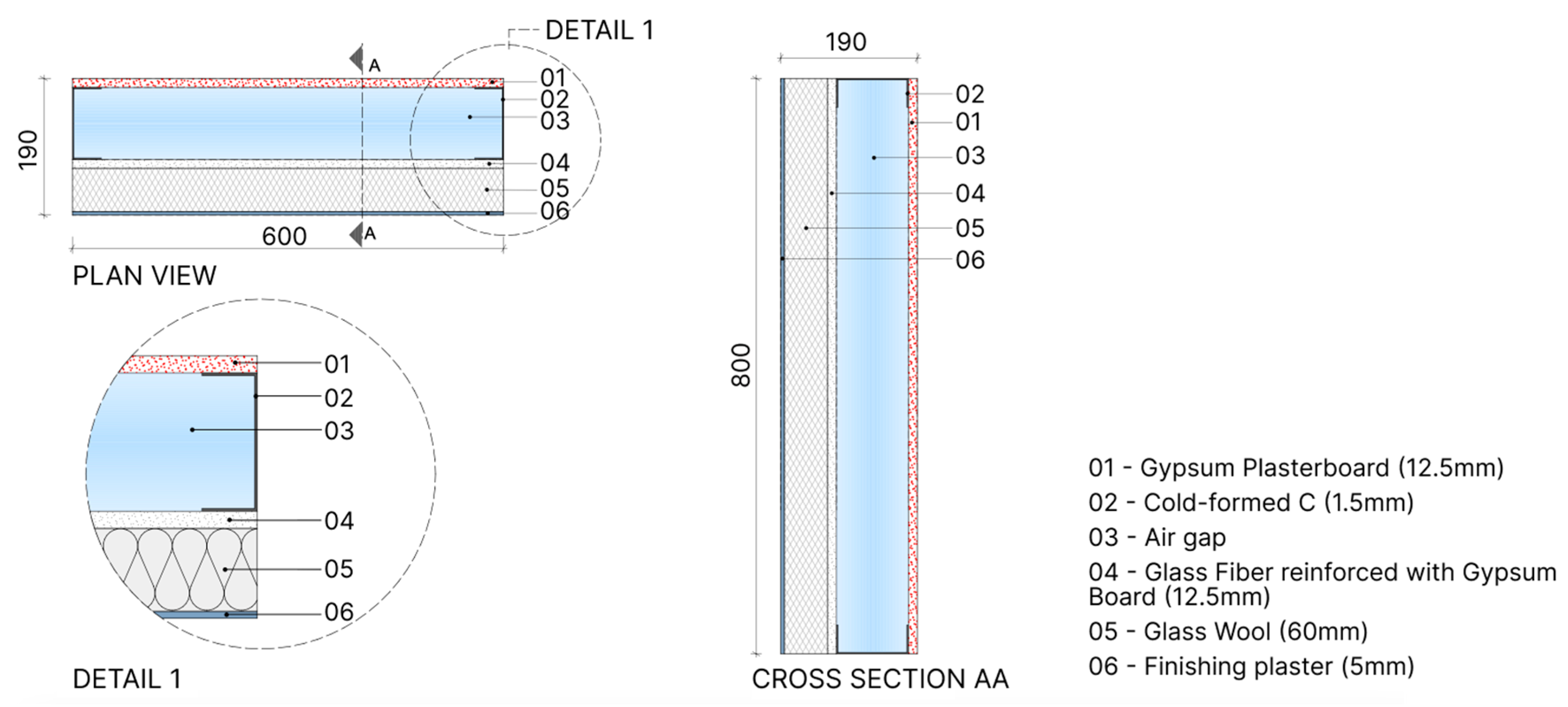
Figure 1. LSF wall panel composition (dimensions in mm).
Buildings 15 00194 g001
Figure 2. Summary of methodological research procedure.
Buildings 15 00194 g002
Figure 3. LSF wall panel.
Buildings 15 00194 g003
Figure 4. Numerical LSF model with optimized steel studs.
Buildings 15 00194 g004
Figure 5. Optimized slotted steel studs—Group 1 (dimensions in mm).
Buildings 15 00194 g005
Figure 6. Use of a rigid polyamide member of the steel stud web—Group 2.
Buildings 15 00194 g006
Figure 7. Different types of fold of the web—Group 3.
Buildings 15 00194 g007
Figure 8. Model general information. (a) Mesh details; (b) LSF wall panel with the mesh detailed; (c) Cross-section of the wall panel.
Buildings 15 00194 g008
Figure 9. Heat flux of reference-steel stud.
Buildings 15 00194 g009
Figure 10. Heat flux of steel studs—Group 1.
Buildings 15 00194 g010
Figure 11. Heat flux of steel studs—Group 2.
Buildings 15 00194 g011
Figure 12. Heat flux of steel studs—Group 3.
Buildings 15 00194 g012
Figure 13. Steel studs heat flux results.
Buildings 15 00194 g013
Figure 14. Heat flux and temperature evolution after the model calibration.
Buildings 15 00194 g014
Figure 15. Heat flux results of wall solution with modified web of the steel studs.
Buildings 15 00194 g015
Figure 16. Heat flux comparison for the different steel studs and insulation variation.
Buildings 15 00194 g016
Figure 17. Heat Flux in LSF wall panels without and with 60 mm insulation.
Buildings 15 00194 g017
Table 1. Thermophysical properties of the materials.
Material (Supplier Data)Thickness (mm)Density (kg·m−3)Thermal Conductivity (W·m−1·K−1)Specific Heat (J·kg−1·K−1)
Finishing plaster512000.4001090
Glass wool 601150.034840
Glass fiber reinforced with gypsum board 12.58720.186840
Gypsum plasterboard 12.59440.250950
Cold-formed C 1.5 mm1.5785060.50434
Finishing plaster512000.4001090
Disclaimer/Publisher’s Note: The statements, opinions and data contained in all publications are solely those of the individual author(s) and contributor(s) and not of MDPI and/or the editor(s). MDPI and/or the editor(s) disclaim responsibility for any injury to people or property resulting from any ideas, methods, instructions or products referred to in the content.