Article

Design and Shear Bearing Capacity Calculation of All-Welded Irregular Joints in Steel Traditional Chinese Buildings

1
Department of Civil Engineering, Luoyang Institute of Science and Technology, Luoyang 471023, China
2
Henan International Joint Laboratory of New Civil Engineering Structures, Luoyang 471023, China
3
College of Civil Engineering and Architechture, Hainan Univerisitey, Haikou 570228, China
*
Author to whom correspondence should be addressed.
Buildings 2025, 15(2), 184; https://doi.org/10.3390/buildings15020184
Submission received: 30 November 2024 / Revised: 30 December 2024 / Accepted: 6 January 2025 / Published: 10 January 2025
(This article belongs to the Section Building Structures)

Abstract

Steel traditional Chinese buildings (STCBs) are constructed using modern materials, replicating the esthetics of ancient Chinese buildings, but their irregular joints differ significantly from those in conventional steel structures. To investigate the influence of beam section shape and axial compression ratio on the failure mode and shear resistance of all-welded irregular joints (WIJs) in STCBs, the size proportion relationships in the traditional Chinese modular construction system for such joints in existing practical projects are analyzed. Four exterior joint specimens were designed and fabricated for pseudo-static loading tests. The failure mode, hysteresis curve, and skeleton curve of the specimens were obtained. The test results indicate that the failure mode of the specimens involves shear deformation in the lower core area, with final failure due to crack formation in the weld at the junction between the column wall and the beam flange. As the axial compression ratio increases, the bearing capacity of the joint decreases. Based on the test results, the numerical model was established by using finite element software Abaqus2016, and parameter analysis was performed by varying the axial compression ratio of the column. After analyzing the force transfer mechanism of the core area in the WIJs of STCBs, a simplified calculation formula for the shear bearing capacity of the core area was derived based on the proportional relationship outlined in the construction manual from the Song Dynasty. The calculated results show good agreement with the experimental results, providing a basis for the structural design of WIJs in STCBs.

1. Introduction

Chinese traditional culture has given rise to a unique architectural culture. Traditional Chinese buildings (TCBs) reflect the outstanding architectural techniques and artistic achievements of ancient China [1]. Its architectural style is distinct from Western architecture and has influenced neighboring countries such as Vietnam. The most important characteristics of traditional Chinese architecture include wooden frames as the primary structural form, magnificent tou kung (bracket set), with ts’ai, ch’i, and tou-k’ou serving as the building module, and the component sizes following a fixed proportion. Under the cultural and social conditions of the time, this characteristic was passed down through the teacher–apprentice system and within families. Although the limitations were significant, and there was a lack of scientific calculation, it still ensured that the architect could choose a reasonable structural scheme, guide the construction, and ensure the safety of the building’s structure. This is also one of the reasons why these architectural gems, despite being damaged, continue to stand in China after thousands of natural disasters and wars [2]. Examples include the Yingxian Wood Pagoda (1056 AD) and the Main Hall of Foguang Temple in Wutai Mountain (857 AD) in Shanxi Province.
In the current era of ideological and cultural diversity, in addition to preserving these valuable cultural heritages, how to inherit and innovate traditional Chinese architecture with national style and regional characteristics in the new era presents a major challenge. With the continuous advancement of building technologies and materials, Chinese architectural engineers have conducted a series of explorations on how to preserve the style of traditional buildings while meeting modern functional needs. The study of ancient wooden architecture primarily focuses on mortise and tenon joints, the bracket set, framing, and the overall structure, which has led to a series of relatively mature research outcomes [3,4,5,6,7].
With the depletion of wood resources and growing emphasis on environmental sustainability, the materials used in TCBs have gradually transitioned to modern alternatives [8], primarily categorized as concrete traditional Chinese buildings (CTCBs) and steel traditional Chinese buildings (STCBs). In recent years, Chinese scholars have carried out extensive engineering practices at TCB, particularly in Xi’an and Luoyang, two of China’s oldest cities, where a large number of traditional Chinese-style buildings with Tang Dynasty architectural characteristics can be found, including temples, memorials, museums, heritage sites, gardens, and towers. The project mentioned above replaces wood with concrete or steel in traditional-style architecture, overcoming the technical limitations of wood and achieving remarkable artistic results. For instance, the Danfeng Gate Site Museum in Xi’an, Shaanxi Province, utilizes modern steel structural technology and materials, as shown in Figure 1b, achieving both contemporary functionality and alignment with regional cultural characteristics. It integrates the ancient charm and modern elements of the Tang Dynasties, showcases distinct national cultural characteristics, and has become a new landmark in Xi’an. Due to its high strength and ease of installation [9,10,11], steel structure technology is particularly suitable for long-span buildings, making it widely applied in TCBs. Consequently, STCBs have emerged as a significant research focus. The beam–column joint is the most vulnerable area to damage within the entire structure. Therefore, the design of the joint is typically one of the key challenges in structural design. Through the analysis and review of traditional steel-structured buildings, it has become evident that certain key technical problems in the design of steel-structured traditional buildings need to be addressed. The conventional steel beam–column joint typically consists of a single column and a single beam.
To enhance the structural integrity and stability of STCBs, two lintels with differing cross-sections are typically required to connect the pillars. Components of STCBs must retain the esthetic qualities of ancient Chinese architecture while adhering to modern structural safety standards [12]. Accordingly, in STCB design, circular pipes are generally used for columns, while beam sections adopt H-section or box-section forms. The tou kung (bracket set), which was traditionally a load-bearing element, now serves purely as a decorative component placed atop the columns. Consequently, the upper rectangular tube, lower circular pipe, and beams with different cross-sections are welded together to form an all-welded irregular joint [13], as illustrated in Figure 2.
Domestic and international scholars have conducted a series of studies on STCBs. These studies include the hysteretic properties of STBC transition columns [14,15,16], dual-lintel column joints [17,18], the damage evolution mechanism of the steel frame in STBCs [19,20] under cyclic loads, and the earthquake response of traditional tower-style buildings under seismic intensity [21]. Based on this, experimental studies on viscous damping technology [22,23] and friction shock absorbers [24,25] in STBCs joints have also been carried out. Qi summarizes the research progress of STBCs from two aspects of seismic performance and engineering application [26]. The research content includes engineering practice, seismic performance studies of transition columns, dual-lintel column joints, steel frame, and traditional tower-style buildings. The research methods employed include experimental studies, numerical analysis, and theoretical analysis. The research results encompass hysteretic properties, damage evolution mechanisms, and seismic responses. Relatively, systematic results have been provided by these studies in this field. It should be noted that the mechanical behavior of beam–column joints is regarded as the core component of these studies. Therefore, references [14,15,16] investigated the seismic performance of the transition column, an important component of the irregular joints in STCBs, as described in references [12,13]. On this basis, the seismic performance of dual-lintel column joints in STCBs was examined in references [17,18]. The research indicated that, although the structure of this type of joint is complex, good seismic performance can still be achieved through reasonable design. This is then extended to the steel frame in STCBs [19,20]. Finally, a shaking table test of a traditional tower-style building was conducted [21]. The limitation identified in this type of joint is that its ductility is lower than that of conventional steel joints due to the all-welded connection, which is primarily governed by the structural requirements of traditional architectural characteristics. Therefore, references [22,23,24,25] investigate the use of viscous and friction dampers at the “sparrow brace” position of STCBs joints and conduct experimental research. The findings show that the installation of dampers improves the seismic performance and ductility of the joints and enhances their failure modes.
Many researchers have investigated the seismic performance of steel joints with circular columns through experimental and numerical analyses. However, studies on irregular joints in STCBs, both domestically and internationally, remain limited, and no effective design methods have as of yet been proposed. In a series of studies on STCBs, it has been increasingly recognized that such buildings follow the modular system found in TCBs, with the main dimensions of the beam–column joints adhering to a fixed proportional relationship. Although existing studies have covered a wide range of topics, from the seismic performance of transition columns and dual-lintel column joints to steel frames, the beam–column joint with dampers has been systematically studied and optimized. However, some limitations in the existing research have also been identified, including the absence of simplified formulas for the shear capacity of irregular joints in STCBs, particularly those suited to the structural characteristics of TCBs. Additionally, there is a lack of research on the size proportion relationship followed by the main components in the joints of STCBs, which is crucial for the design of such joints. To address this research gap, it is essential to develop a simplified calculation formula for the shear strength of STCBs. In this study, the failure modes and force mechanisms of four joint specimens with all-welded irregular joints (WIJs) in STCBs in the Tang Dynasty were investigated through pseudo-static tests. The “strong members-weak joints” design method was adopted in the experimental design to ensure that failure occurs first in the core region, allowing for the determination of the failure sequence in the three small core regions. Based on the observed failure modes in the core area and the structural characteristics of ancient Chinese buildings, a shear capacity calculation formula was derived. The formula accounts for the influence of the axial compression ratio and beam section form, particularly the dimension ratio relationships inherent in the modular system of TCBs. The findings of this research provide valuable insights and a practical reference for the engineering application and structural design of STCBs in the Tang Dynasty.

2. Experimental Investigation

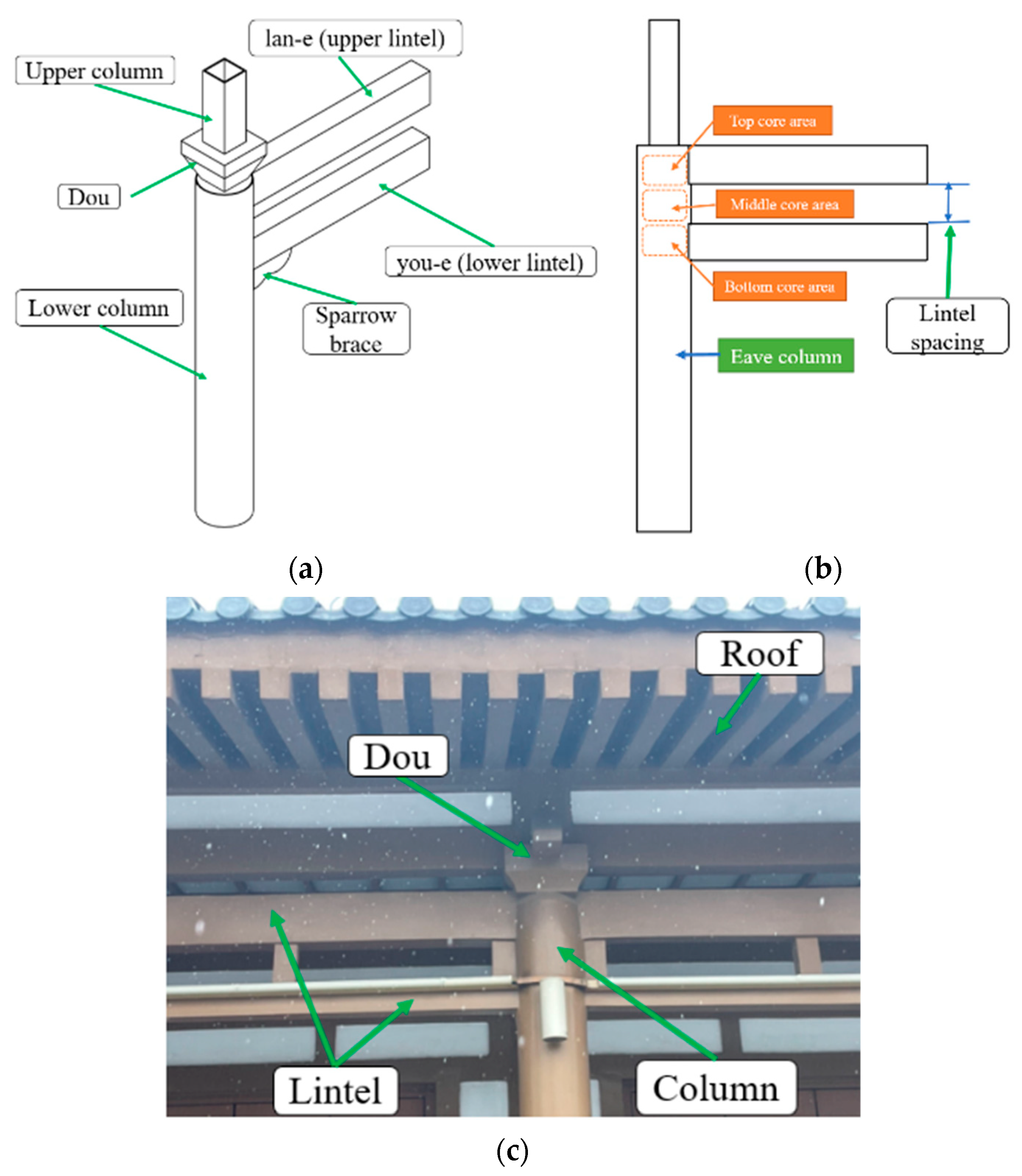
2.1. Construction and Design Method

The tou kung [bracket set] plays a leading role in TCBs and is highly valued for its structural and esthetic functions. Steel bracket sets are typically connected to the columns using bolts, which require the columns to be constructed from rectangular tubes. To install the bracket set and other decorative components, the cross-sectional dimensions of the upper rectangular tube must be reduced. Horizontal stiffening plates and vertical stiffening ribs are welded onto the lower circular pipe to form a “transitional steel connection”. This transitional steel connection, together with two lintels of different cross-sectional dimensions, forms a unique type of joint. The larger cross-sectional lintel is referred to as the “lan-e”, while the smaller one is known as the “you-e”. Due to its dual-lintel characteristics and the necessity of welding between components, this joint is referred to as a WIJ in STCBs, as shown in Figure 2.
A well-regulated set of rules governing design and execution emerged during the development of ancient Chinese architecture. Two important government manuals, Ying-tsao fa-shih of the Song Dynasty and Kung-ch’eng tso-fa tse-li of the Qing Dynasty, provide foundational guidelines for these practices [27]. The size of a standard joint in TCBs must conform to the modules known as ts’ai and ch’i. In the design process, the architectural grade is determined by the building type and official rank, followed by the calculation and determination of key architectural parameters, such as the dimensions of the main columns. Subsequently, the diameter and height of the eave columns are established based on the architectural grade. The height and width of the beam cross-section can then be derived from proportional relationships with the eave columns. Additional parameters, including the wall thickness of round steel pipe columns, the thickness of beam flanges, and web thickness, are calculated using mechanical principles.
Taking the second-grade temple building of the Tang Dynasty as an example, its dimensions conform to the guidelines outlined in the Ying-tsao fa-shih of the Song Dynasty [27], where one fen equals 17.16 mm. The diameter of the eave columns is forty-two fen. The cross-section of lintels consistently maintains a 3:2 ratio between depth and width. Specifically, the height and width of the “lan-e” are thirty and twenty parts, respectively, while those of the “you-e” are twenty-seven and eighteen parts, respectively. The diameter of the eave columns and the cross-section of lintels can be determined through dimensional conversion. The eave columns are constructed from seamless round steel pipes with dimensions approximating the traditional measurements. The diaphragm head and the box-section beam are fabricated from steel plates, welded together at the front. Similarly, the upper column is assembled from steel plates to form a box-section column. The ends of the beams are cut along the arc of the round steel pipe and welded to its wall for structural integrity. According to the Ying-tsao fa-shih of the Song Dynasty, the distance between the “lan-e” and the “you-e” should be half the height of the “lan-e”. However, in practical applications, considering both the esthetic and construction requirements of TCBs, the distance between the two lintels is often equal to the height of the “lan-e”.

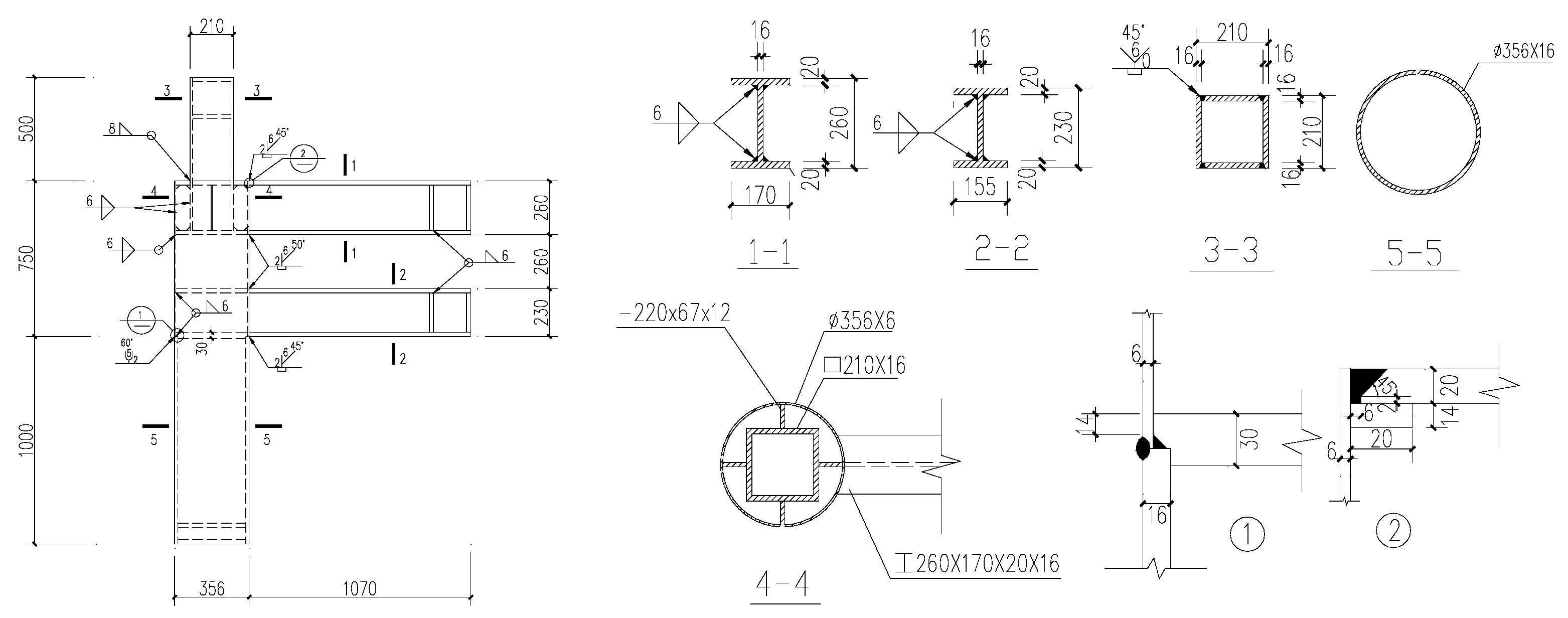
2.2. Specimen Design
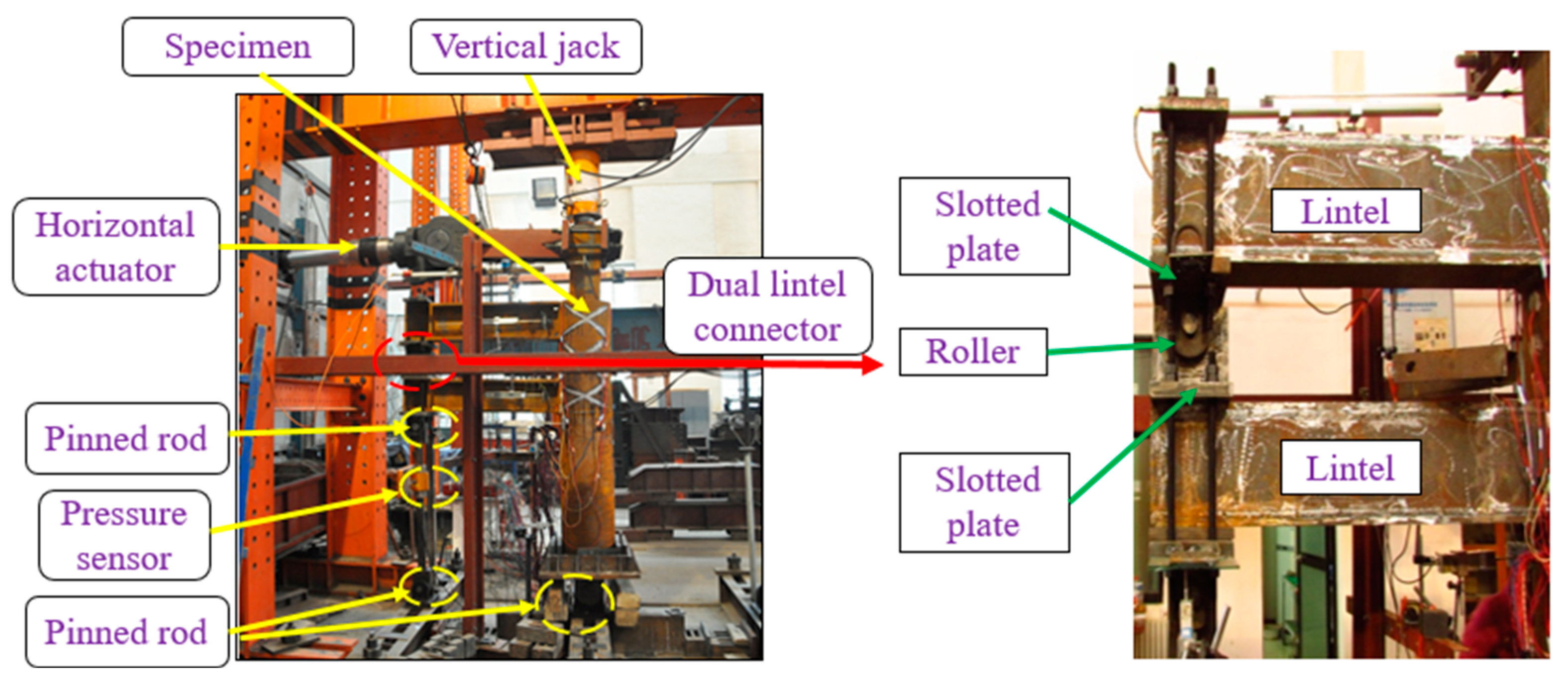
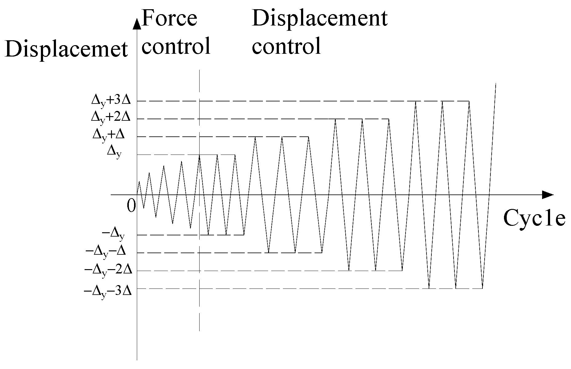
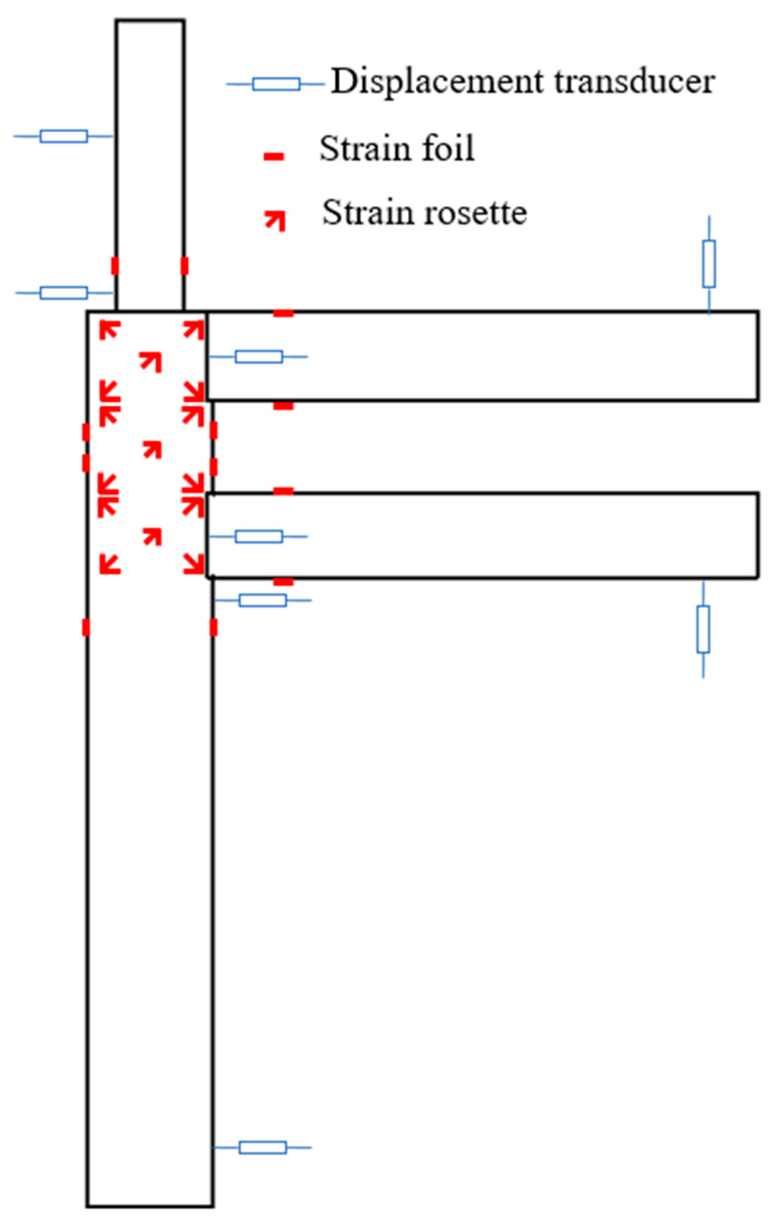
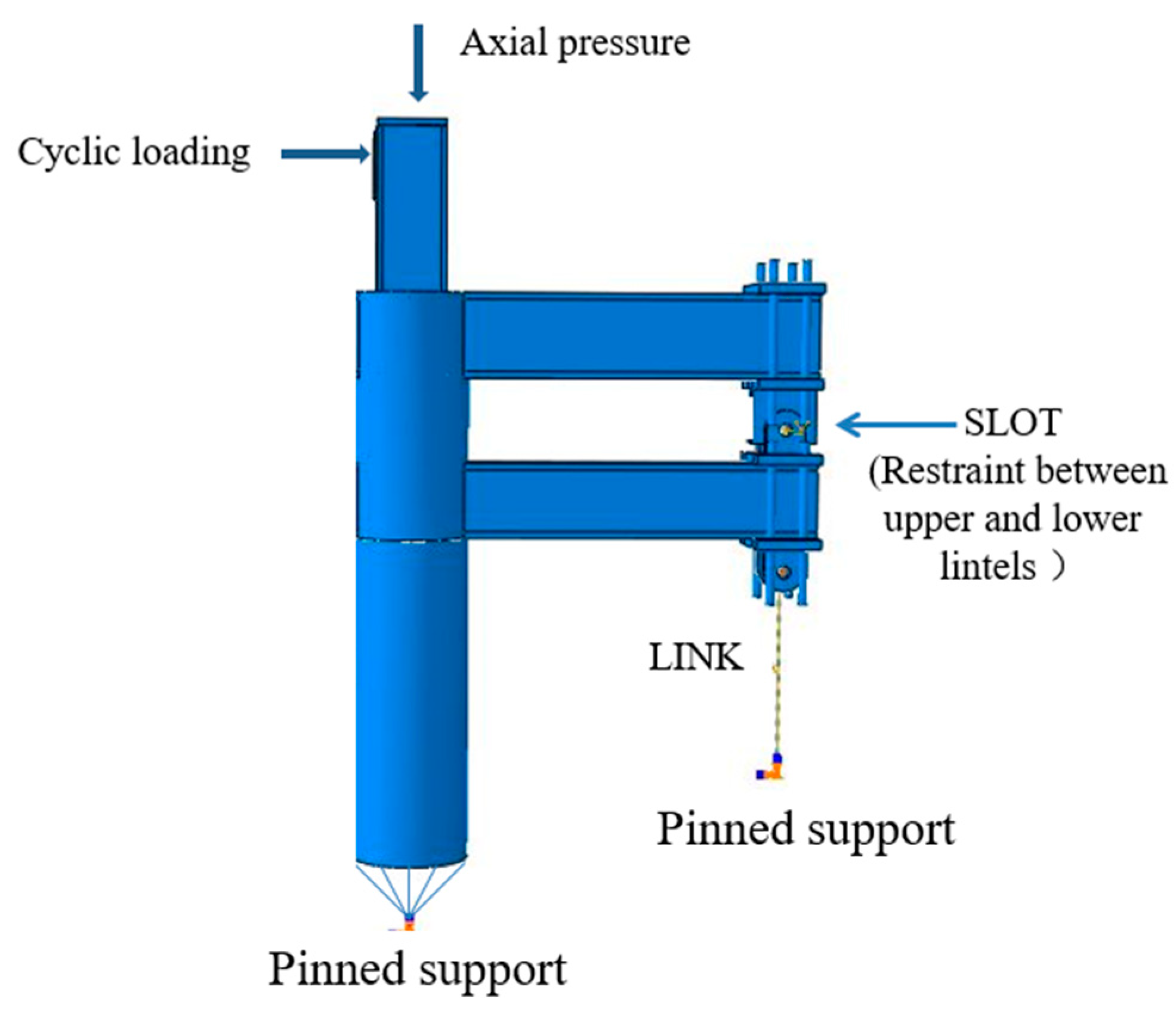
In this study, four 1:2 scaled specimens were fabricated, including two box-section lintel exterior joints and two H-section lintel exterior joints in STCBs. The prototype for the specimens was based on a second-grade temple building from the Tang Dynasty located in Xi’an City, Shaanxi Province. Considering the loading capacity of the laboratory, a seamless steel pipe with a diameter of 356 mm was selected for the eave column after scaling down the prototype dimensions by a factor of 2. The heights of the lintels were 260 mm and 230 mm, respectively, with a spacing of 260 mm between them. The axial compression ratios applied were 0.3 and 0.6. To investigate the mechanical behavior of the core area in the irregular joints of STCBs and to derive the shear capacity of these joint cores, it was essential to observe the failure modes of the specimens, particularly focusing on the mechanical behavior and yield sequence within the three small core areas. This study deviated from the conventional “strong joints and weak members” design approach. Specifically, the lower circular pipe was divided into two sections: the core area’s wall thickness was set to 6 mm, whereas the non-core area’s wall thickness was 16 mm [28]. Additionally, circular reinforcing plates with a thickness of 20 mm were welded inside the column at the corresponding height of the beam flanges. All welds in the specimens were executed using full penetration welding techniques. The primary parameters of the specimens are illustrated in Figure 3 and summarized in Table 1. The base material for the specimens was Q235 steel. Reinforcing filet welds, following the guidelines in the Code for Welding of Steel Structures [29], were applied using E43 filler metal to construct the specimens. The results of the coupon tests [30] are presented in Table 2.

2.3. Test Methods

To accurately simulate the forces acting on the WISJs in STCBs during horizontal earthquakes, the arc plate at the bottom of the column was fixed within the chassis of the hinge support. This setup replicated the forces encountered at the reverse bending point of the column. A roller was positioned between the reaction beam and the vertical jack to allow for horizontal free sliding at the top of the column. A 1000 kN hydraulic jack was used to apply axial pressure at the top of the column, maintaining a constant value throughout the test [31]. A special dual-lintel connector was installed between the top and bottom lintels to simulate the actual force conditions, as shown in Figure 4. This connector facilitated vertical force transfer between the beams while preventing the transmission of horizontal shear forces. Additionally, a fixed hinge support, equipped with tension and pressure sensors, was placed at the lower lintel (the “you-e”) to replicate the forces acting at the reverse bending point of the lintels. A cyclic load was applied at the top of the column using an MTS-973 servo loading system, manufactured by Beijing Fluid Control System Corp, China. Initially, the cyclic load was increased by 30 kN for different cases. After the specimen yielded, the load was incremented by 10 kN at each stage, with three cycles repeated for each increment. The test loading device and loading procedure are presented in Figure 4 and Figure 5. The primary focus of the test was on the core area of the joint. Therefore, additional resistance strain gauges were installed in the core area of the node, as well as in the plastic hinge area at the beam end and on the flange of the column, as shown in Figure 6.

3. Test Results

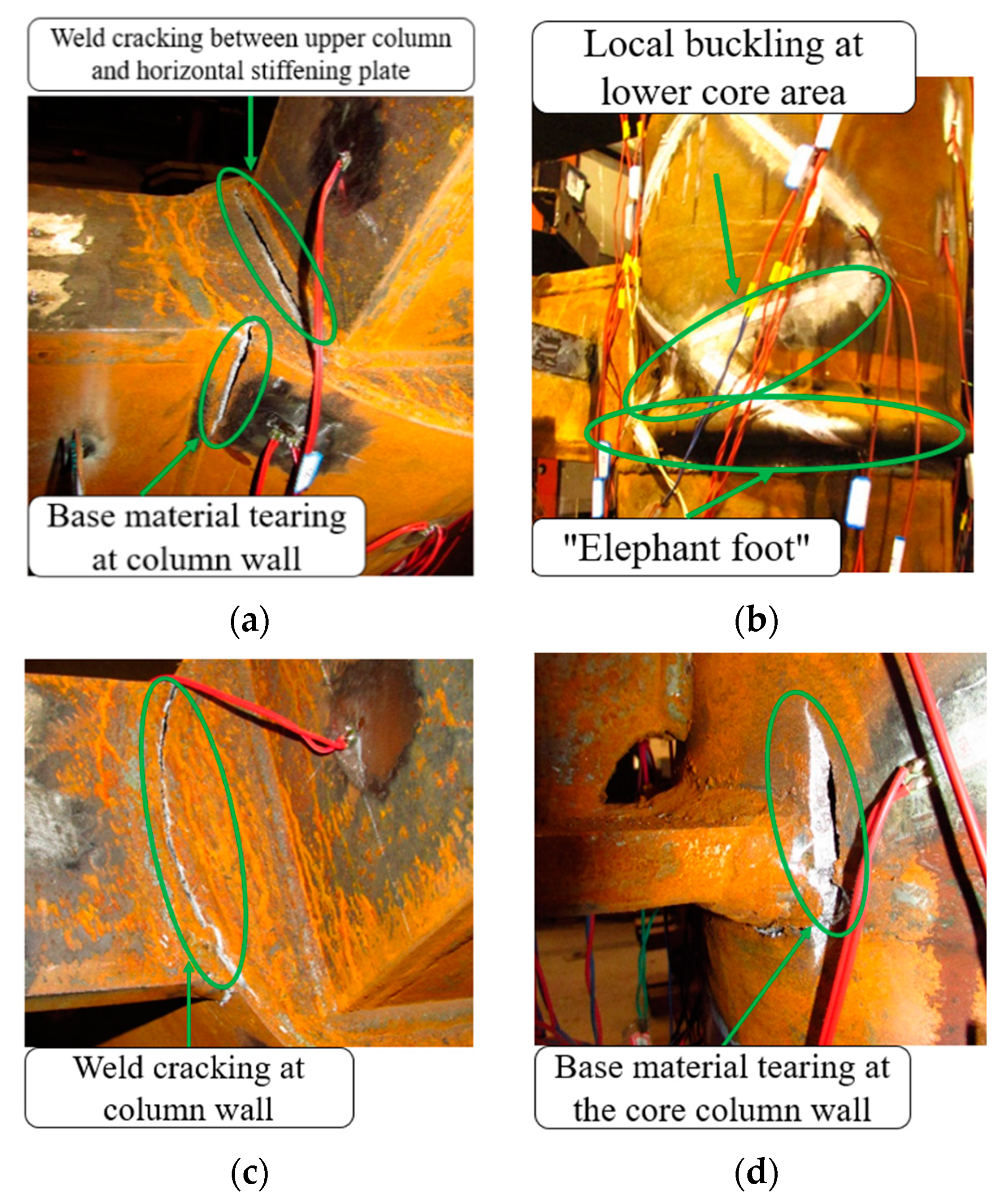
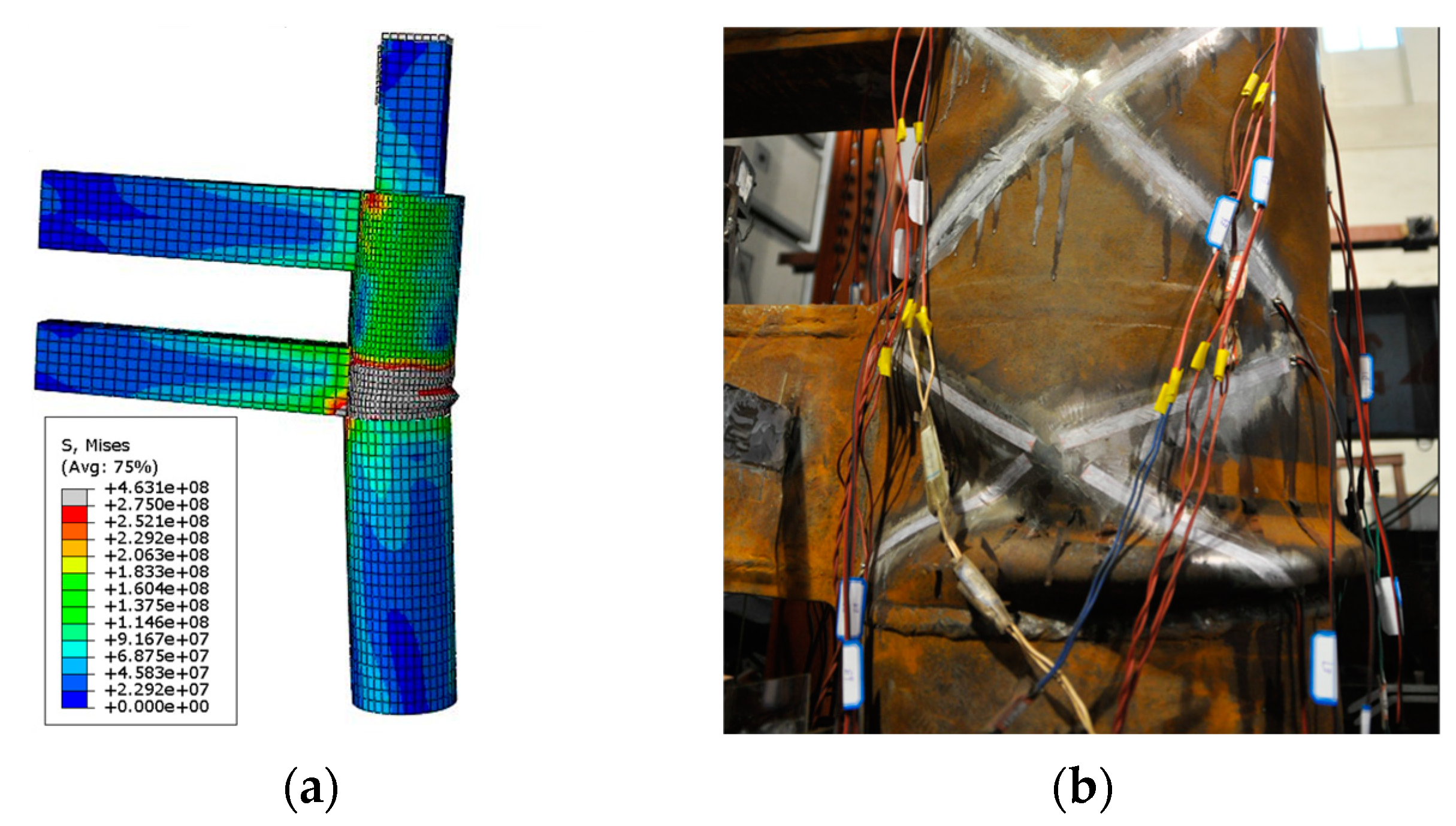
3.1. Failure Patterns

All specimens initially failed in the lower core area, with damage subsequently propagating to the central core area. Shear deformation was identified as the predominant failure mode in the lower core area, whereas lateral bending deformation dominated in the central core area. In contrast, no visible damage was observed in the upper core area due to the presence of stiffeners, which significantly enhanced stiffness. The axial compression ratio had a pronounced effect on the deformation behavior, bearing capacity, and failure modes of the specimens. Under higher axial compression ratios, more severe buckling was observed in the core area, particularly in specimens with box-section lintels. For specimen BJD1, which was subjected to a lower axial compression ratio of 0.3, failure occurred at the weld between the west base of the upper column and the circular stiffening plate when displacement control reached 100 mm. Micro-cracks also developed at the connection between the upper flange of the diaphragm head and the column wall. Eventually, the two ends of the diaphragm’s upper flange were pulled apart from the root along the web column wall, as shown in Figure 7a. In contrast, specimen BJD2, with a higher axial compression ratio of 0.6, exhibited an external bulge on the beamless side at the bottom of the lower core region. This bulge resembled an “image foot”, as illustrated in Figure 7b. This phenomenon was attributed to stress redistribution in the joint’s core area under increased axial compression ratios, which mitigated damage near the flange.
The cross-sectional shape of the lintels had a significant impact on the failure pattern of the specimens. For box-section lintel specimens, the end web in the core area exerted greater constraints on the deformation of the steel tube wall compared to H-section lintel specimens, resulting in more pronounced plastic deformation in the core area. In contrast, the beam end of the H-beam specimens imposed less constraint on the column wall deformation in the joint core area. Under cyclic loading, initial cracks were observed at the corner of the weld between the upper flange of the upper lintel and the column flange. With the increase in load, the fracture progressively propagated, eventually tearing the column wall, as shown in Figure 7d. For specimens subjected to smaller axial loads, failure primarily occurred at the weld between the upper flange of the upper lintel and the column wall, leading to the development of through cracks, as illustrated in Figure 7c.

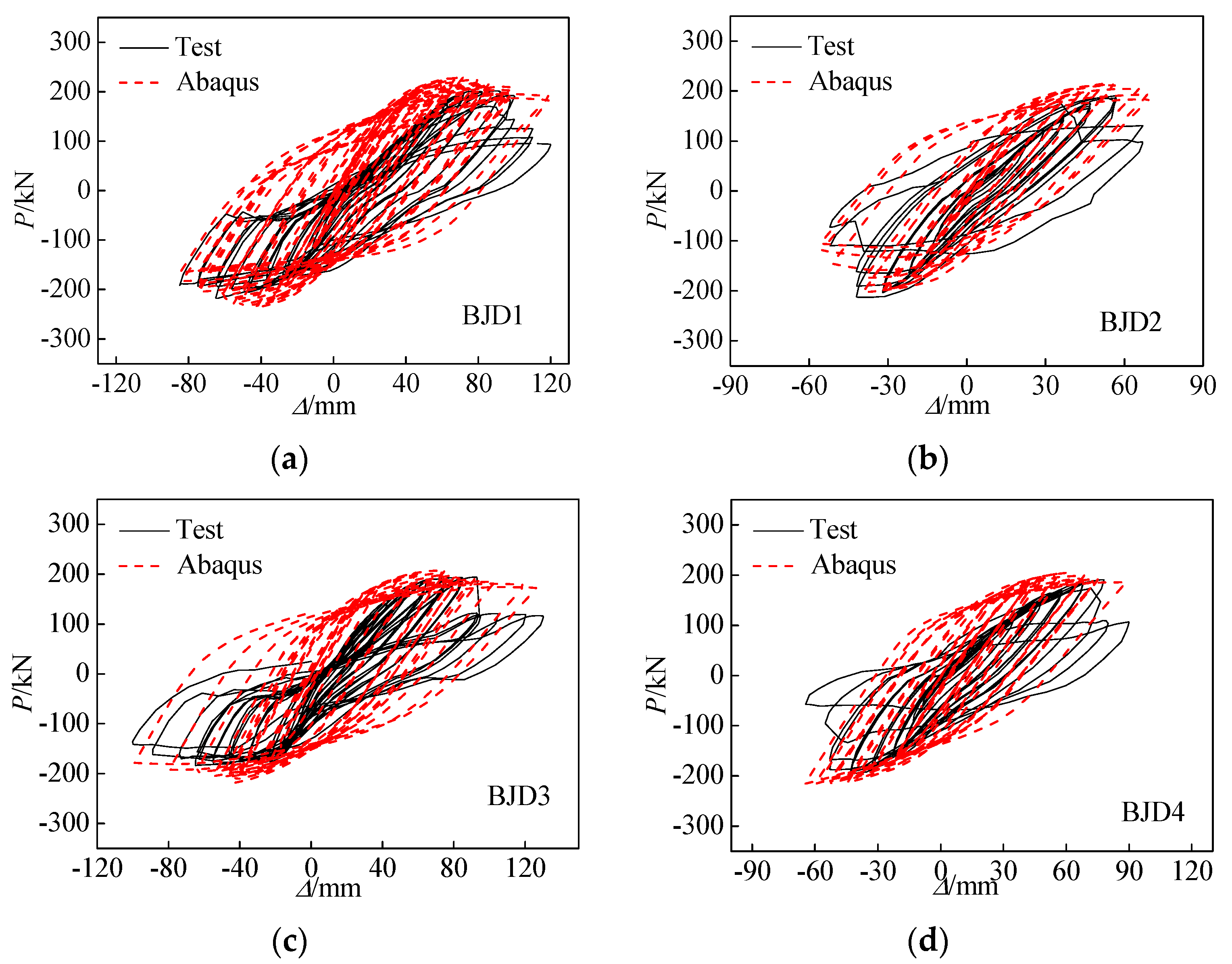
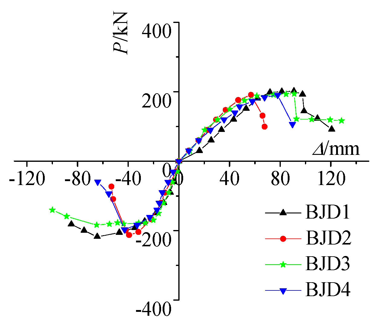
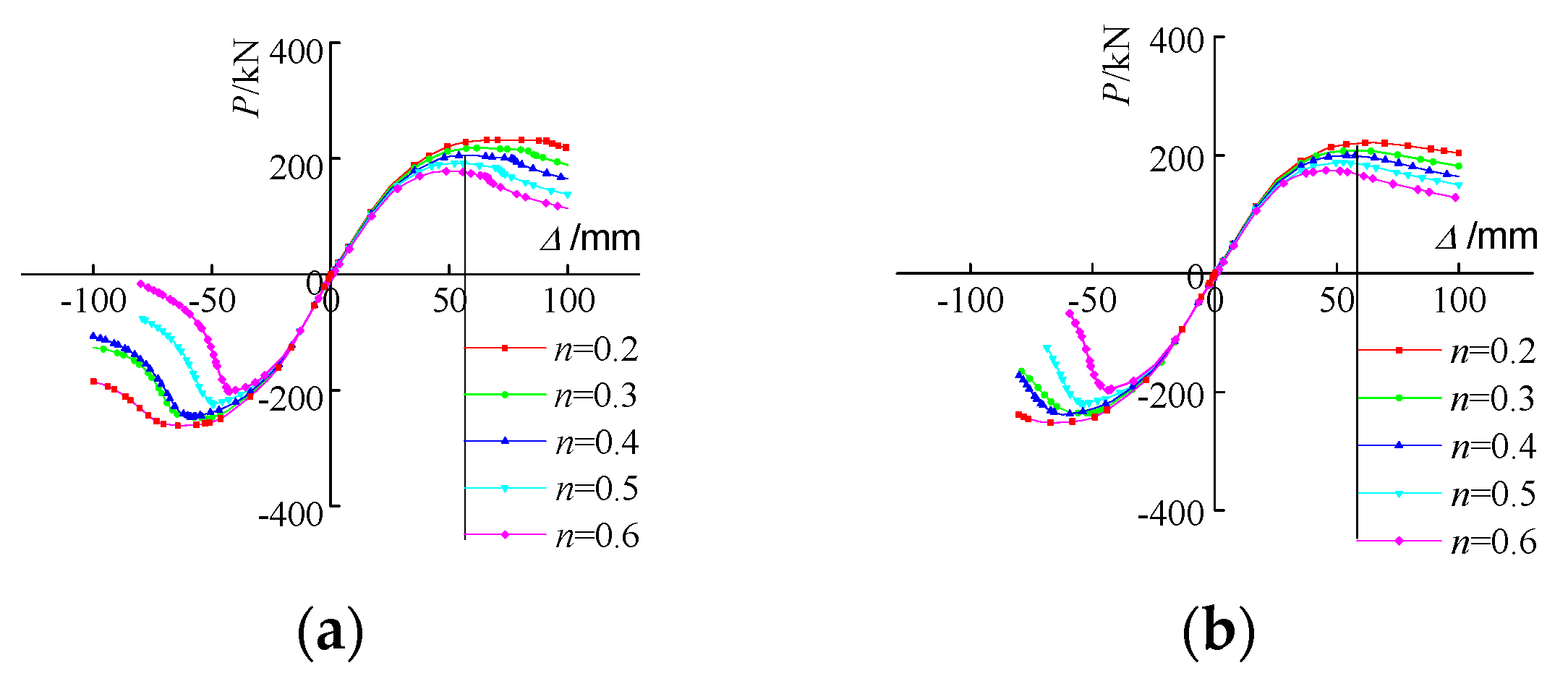
3.2. Load–Displacement Curves

The load–displacement hysteretic curve and skeleton curve of the specimens in this test are presented in Figure 8 and Figure 9, respectively, where P and Δ denote the cyclic load and the corresponding horizontal displacement at the top of the column. At the initial stage of loading, the hysteretic curves exhibited a generally linear relationship. As the horizontal displacement at the column top increased, the deformation in the core area of the specimens also intensified. Consequently, the area enclosed by the hysteresis loops gradually expanded, and the loop shapes evolved into a fusiform pattern. Upon entering the elastoplastic stage, specimens with a higher axial compression ratio (n = 0.6) exhibited an earlier onset of load degradation as displacement increased, accompanied by a steeper decline in load. This behavior indicates that greater axial compression ratios led to more severe deformation in the core area, base metal fractures, and tearing failures in the specimens. Figure 9 shows that the bearing capacity of joint specimens was significantly influenced by the axial compression ratio. Specimens with lower axial compression ratios exhibited higher ultimate bearing capacities. In contrast, the core areas of specimens with higher axial compression ratios yielded earlier, reaching their yield strength more quickly and transitioning to the elastoplastic stage sooner.

4. Finite Element Analysis

4.1. FEA Models

Based on the general finite element software Abaqus2016, a finite element model of the specimen was established. Ignoring the initial defects of the welds and materials, three-dimensional structural solid elements C3D8R were used in the model. The stress–strain relationship of the steel was simulated using an elastic–plastic trilinear model [19]. Poisson’s ratio was set to 0.3, and the section sizes of the beams and columns were consistent with those of the joints in the experiment. The boundary conditions and loading methods were matched with those in the tests. The constraints between the upper and lower lintels were simulated using SOLT units. The finite element model is shown in Figure 10.

4.2. Verification of Finite Element Model

The comparison of hysteresis loops between the test and FEA is shown in Figure 8. Taking the BJD2 specimen as an example, the deformation comparison between the test and finite element is shown in Figure 11.
There are some differences between the test results and the finite element analysis results, mainly due to the presence of gaps between the testing device, the beam end loader, and the pin connection, which may cause slight slipping. The finite element model does not account for the effects of initial defects, welding residual stresses, weld cracking, and base metal tearing. However, the failure mode and hysteresis curve agree well, indicating that the modeling method selected for the finite element analysis is reasonable.

4.3. Effects of the Axial Compression Ratio

Other parameters were kept unchanged, with only the axial load at the column top being varied. The axial compression ratios of the column were set to 0.2, 0.3, 0.4, 0.5, and 0.6. The finite element calculation results are shown in Figure 12.
As shown in Figure 12, changes in the axial compression ratio of columns have little effect on the stiffness of the specimens during the initial loading stage but have a greater influence on the ultimate bearing capacity after yielding and on the shape of the descending section. The yielding load and peak load of specimens with a higher axial compression ratio are both lower, and the descending section appears earlier. This is because specimens with a higher axial column load are more significantly affected by the P-Δ effect, leading to earlier shear deformation in the joint core area, with more severe deformation after yielding.

5. Analysis of Shear Capacity

The diagram of the main dimensions of the lower core area is shown in Figure 13. The force analysis and test results revealed that the primary factors influencing the shear strength of WIJs in STCBs are the axial compression ratio and the cross-sectional shape of the lintels. To evaluate the contribution of the lintel cross-sectional shape to the deformation of the joint core area, a calculation formula for the shear strength of the core area was developed. This formula is based on the shear strength calculation framework for the core area of steel structures outlined in the American Institute of Steel Construction (AISC) code [32], modified to account for the unique configurations of WIJs in STCBs described in this study. The proposed formula is expressed as follows:
V = η D t f y ( 1 + 3 b cf t cf 2 d b d c t w )
where η is the adjustment coefficient of shear strength, and D and t are the diameter and wall thickness of the core area in the circular pipe, respectively. fy is the yield strength of steel in the core area; bcf and tcf are the width and thickness of the column flange, respectively; db is the height of the cross-section of the lintel; and dc and tw are the height of the column cross-section and thickness of the web at the core area, respectively.
It is evident that Formula (1) involves numerous parameters, which complicates its application in design. Based on the design methodology for WIJs in STCBs outlined in Section 2, the primary dimensions of the specimens can be determined once the diameter and wall thickness of the circular pipe are specified. The specifications of ancient Chinese buildings, as well as the proportional relationships between their components, follow fixed rules. The prototype specimen described in this study is a temple building from the Tang Dynasty. The Ying-tsao fa-shih, a construction manual from the Song Dynasty, provides the general rules and proportions used for design and calculation. The essential dimensional parameters of the specimens, as referenced in Formula (1), are summarized in Table 3. In this context, t represents the wall thickness of the core area in the circular pipe, while tcf and tw are defined as t and 2t, respectively. Therefore, Formula (1) can be simplified to Formula (2) as follows:
V = η D t f y ( 1 + 7 t 6 D )
The test results revealed that the core deformation of the specimens became more pronounced and entered the yield stage earlier under higher axial pressure, ultimately influencing the final failure pattern. Consequently, the axial compression ratio was also incorporated into the calculation of the shear strength of WIJs in TCBs. The design parameters and test results of the specimens were applied to Formula (2), and a statistical regression analysis of the data was performed to derive the calculation Formulas (3) and (4) for the shear capacity Vb of the box-section lintel specimen and the shear capacity Vh of the H-section lintel specimen, as follows:
V b = 0.8 D t f y ( 1 n 2 ) ( 1 + 7 t 6 D )
V h = 0.8 D t f y ( 1 n 3 ) ( 1 + 7 t 6 D )
n = N c T f y A s
Formulas (3) and (4) are applicable for calculating the shear strength of WIJs in TCBs, provided that the axial compression ratio does not exceed 0.6.
The proposed formula is applicable for calculating the shear strength of WIJs in TCBs when the axial compression ratio is less than 0.6. During the tests, the shear force Vt in the lower core area was determined based on the beam end load measured by a force sensor at the beam end hinge support. This measurement corresponds to the point when the diagonal strain in the lower core area reaches the yield strain of the steel. The calculated shear strength Vc was obtained by substituting the specimen parameters into Formulas (4) and (5). Table 4 presents a comparison of the experimental results and the calculated shear capacities. As shown in Table 3, the average ratio of the calculated values to the test values was 0.9690, with a standard deviation of 0.0011 and a coefficient of variation of 0.0329. These findings indicate that the calculated values obtained from the formula are in good agreement with the test results, demonstrating that the shear capacity formulas provide accurate and reliable predictions.

6. Conclusions

In this paper, pseudo-static testing was conducted on WIJs in STCBs. The failure modes and force mechanisms of the core area were analyzed, and a shear capacity formula was proposed based on the structural characteristics described in the construction manual of TCBs from the Song Dynasty. The main conclusions are summarized as follows:
  • WIJs in STCBs are characterized by their dual-lintel configuration, which forms three distinct small core regions. The primary failure mode is shear failure in the lower core. Under late-stage loading, the joint between the column wall and the beam tends to crack, which should be carefully considered in the design.
  • The axial compression ratio and the section shape of the lintel have significant effects on the failure mode and bearing capacity of the joint. As the axial compression ratio increases, shear failure in the lower core region becomes more pronounced. The deformation of the lower core region in the box beam specimen is larger than that in the H-section beam specimen.
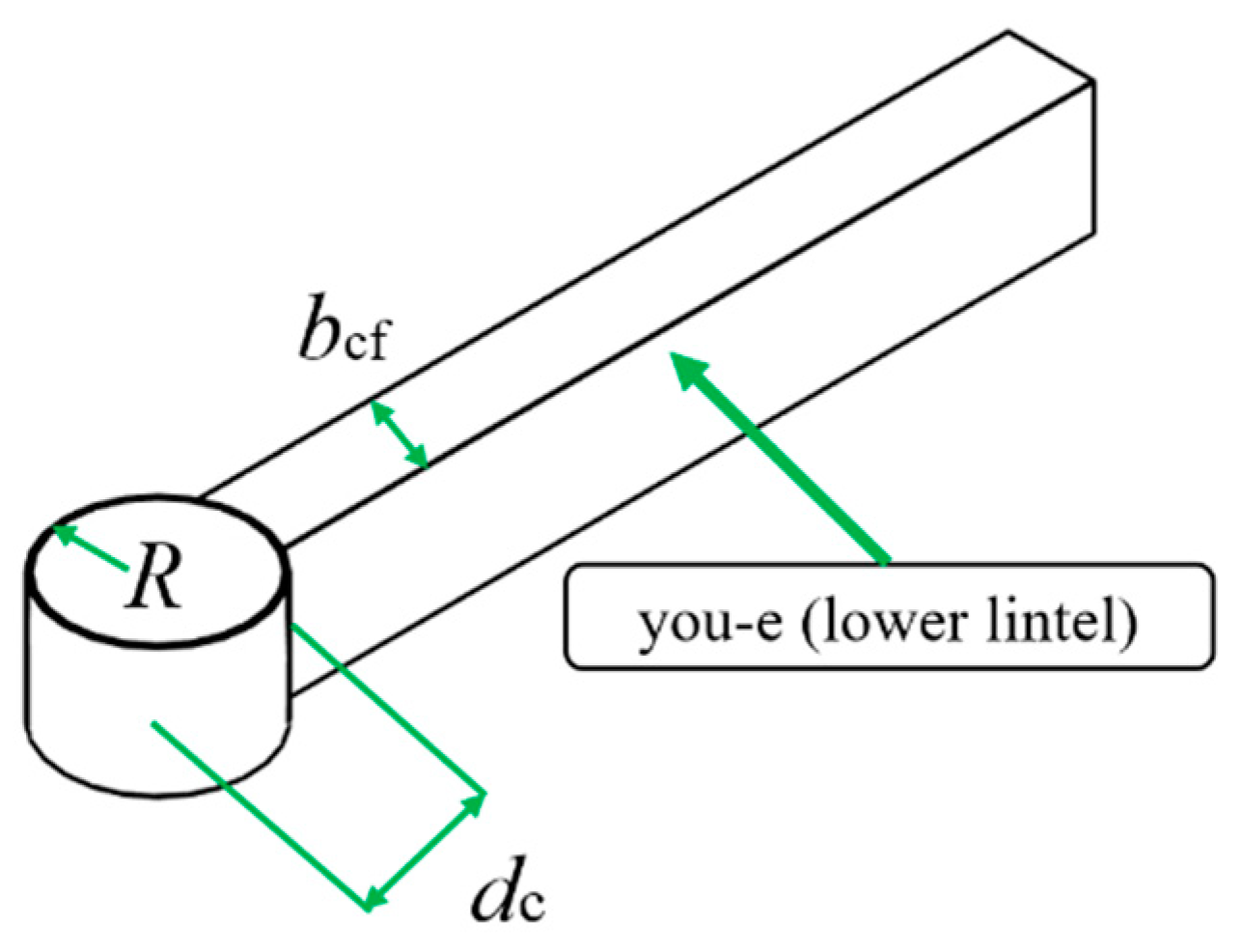
  • Based on the proportional relationship outlined in the Song Dynasty construction manual, a simplified calculation formula for the shear strength of the core region is derived. This formula is applicable to the traditional style of temple buildings in the Tang Dynasty. The calculated results are in good agreement with the experimental findings, providing a theoretical foundation for the seismic design of WIJs in STCBs.
  • Future research will be carried out in the field of STCBs of prefabricated fully bolted connection, while increasing the research on hall and Qing architecture. There will be a focus on joint optimization design using artificial intelligence and machine learning.

Author Contributions

Conceptualization, methodology, formal analysis, writing—original draft preparation, and writing—review and editing, Z.W. Resources, supervision, and funding acquisition, X.W. Validation and visualization, X.B. Investigation and data curation, J.D. All authors have read and agreed to the published version of the manuscript.

Funding

This research was supported by the National Natural Science Foundation of China (Grant No. 52008330) and the Key Scientific Research Project Plan of Henan Province University (grant number: 23B560009). In addition, this work was also supported by the Henan Provincial Department of Science and Technology Research Project (grant number: 242102320318).

Data Availability Statement

The testing and analysis data used to support the findings in this study are included within the article.

Acknowledgments

We would like to thank Yan Sui and Jinshuang Dong for their hard work in the experiment, numerical analysis and formula derivation of this paper. I would also like to thank Xinwu Wang for his guidance on this article.

Conflicts of Interest

The authors declare that they have no known competing financial interests or personal relationships that could have appeared to influence the work reported in this paper.

References

  1. Yang, Q.; Yu, P.; Law, S.S. Load resisting mechanism of the mortise-tenon connection with gaps under in-plane forces and moments. Eng. Struct. 2020, 219, 110755. [Google Scholar] [CrossRef]
  2. Chen, Z.; Zhu, E.; Lam, F.; Pan, J. Structural performance of Dou-Gong brackets of Yingxian Wood Pagoda under vertical load-An experimental study. Eng. Struct. 2014, 80, 274–288. [Google Scholar] [CrossRef]
  3. Song, D.; Xue, J.; Wu, C. Experimental and theoretical study on seismic behavior of Tou-kung brackets on column under the load in overhanging and width directions. Eng. Struct. 2024, 299, 117138. [Google Scholar] [CrossRef]
  4. Zhang, X.; Liu, L.; Qiu, Z.; Cui, L.; Hu, C. Replaceable Displacement-Amplifying Rotary Friction Damper: Experimental and Numerical Investigation. Struct. Control Health Monit. 2024, 1, 9402792. [Google Scholar] [CrossRef]
  5. Dai, N.; Cui, L.; Li, Y.; Fan, L.; Chen, J. A numerical simulation study on the out-of-plane performance of timber framework-brick wall systems in traditional residential Buildings of northern China. Buildings 2024, 14, 1224. [Google Scholar] [CrossRef]
  6. Cui, L.; Zhang, X.; Hu, W.; Meng, Z.; Chen, J.; Qiu, Z. Seismic performance analysis of ancient palace-style building considering column rocking effect. J. Earthq. Eng. 2024, 28, 3175–3190. [Google Scholar] [CrossRef]
  7. Xue, J.; Guo, R.; Qi, L. Experimental study on the seismic performance of traditional timber mortise tenon joints with different looseness under low-cyclic reversed loading. Adv. Struct. Eng. 2019, 22, 1312–1328. [Google Scholar] [CrossRef]
  8. Zhao, H.; Zhang, F.; Xue, J.; Xie, Q.; Zhang, X.; Ma, H. Research review on structural performance of ancient timber structure. J. Build. Struct. 2012, 33, 1–10. [Google Scholar]
  9. Rabi, M.; Abarkan, I.; Shamass, R. Buckling resistance of hot-finished CHS beam-columns using FE modelling and machine learning. Steel Constr. Des. Res. 2024, 17, 93–103. [Google Scholar] [CrossRef]
  10. Abarkan, I.; Rabi, M.; Ferreira, F.P.V.; Shamass, R.; Limbachiya, V.; Jweihan, Y.S.; Santos, L.F.P. Machine learning for optimal design of circular hollow section stainless steel stub columns: A comparative analysis with Eurocode 3 predictions. Eng. Appl. Artif. Intell. 2024, 132, 107952. [Google Scholar] [CrossRef]
  11. Rabi, M.; Jweihan, Y.S.; Abarkan, I.; Ferreira, F.P.V.; Shamass, R.; Limbachiya, V.; Tsavdaridis, K.D.; Santos, L.F.P. Machine learning-driven web-post buckling resistance prediction for high-strength steel beams with elliptically-based web openings. Results Eng. 2024, 21, 101749. [Google Scholar] [CrossRef]
  12. Wu, K.; Jia, J.; Che, S. Structural material evolution and key component design of traditional style building. Build. Struct. 2017, 47, 61–65. [Google Scholar]
  13. Che, S.; Jia, J.; Wu, K.; Wei, S.; Mu, M. Steel structure design of a traditional style pavilion architecture. Build. Struct. 2017, 47, 47–50, 81. [Google Scholar]
  14. Qi, L.; Xue, J.; Leon, R.T. Experimental and analytical investigation of transition steel connections in traditional-style buildings. Eng. Struct. 2017, 150, 438–450. [Google Scholar] [CrossRef]
  15. Xue, J.; Zhai, L.; Gao, W.; Dong, J.; Wu, K. Experimental study on seismic performances of connections between rectanglar steel pipe column and circular steel pipe column in imitated ancient building. J. Build. Struct. 2016, 37, 81–91. [Google Scholar]
  16. Xue, J.; Ma, L.; Wu, Z.; Gao, W. Influence analysis of bracket set on seismic performance of steel eave columns in Chinese traditional style buildings. Struct. Des. Tall Spec. Build. 2018, 27, e1462. [Google Scholar] [CrossRef]
  17. Xue, J.; Qi, L.; Yang, K.; Wu, Z. Dynamic experimental study on single and double beam-column joints in steel traditional-style buildings. Struct. Eng. Mech. 2017, 63, 617–628. [Google Scholar]
  18. Xue, J.; Ma, L.; Wu, Z. Seismic performance of steel joints between double beams and column in Chinese traditional style buildings. Int. J. Steel Struct. 2018, 18, 417–432. [Google Scholar] [CrossRef]
  19. Xue, J.; Qi, L. Experimental studies on steel frame structures of traditional-style buildings. Steel Compos. Struct. 2016, 22, 235–255. [Google Scholar] [CrossRef]
  20. Qi, L.; Xue, J. Pseudo dynamic test and time-history analyses of traditional-style steel frame structures. Int. J. Steel Struct. 2018, 18, 402–416. [Google Scholar] [CrossRef]
  21. Ling, H.; Xue, J.; Qi, L. Shaking table test and numerical analyses of a multi-story traditional tower-style building. Earthq. Eng. Struct. Dyn. 2024, 53, 3184–3204. [Google Scholar] [CrossRef]
  22. Sui, Y.; He, Z.; Xue, J.; Wu, Z. Experimental study and numerical analysis on seismic performance of steel beam-column damping joint in Chinese traditional style buildings. Struct. Des. Tall Spec. Build. 2020, 29, e1710. [Google Scholar] [CrossRef]
  23. Wu, Z.; Xue, J.; Ke, X.; Sui, Y.; Dong, J. Dynamic experimental and numerical study of double beam-column joints in modern traditional-style steel buildings with viscous damper. Struct. Des. Tall Spec. Build. 2020, 29, e1677. [Google Scholar] [CrossRef]
  24. Yuan, Z.; Xue, J.; Qi, L. Seismic performance of steel semi-rigid friction-damped joints with replaceable angles in modern Chinese traditional-style buildings. J. Constr. Steel Res. 2023, 207, 107948. [Google Scholar] [CrossRef]
  25. Qi, L.; Yuan, Z.; Xue, J. Experimental and numerical study on seismic performance of steel semi-rigid joints equipped with SMA bars and friction dampers. Eng. Struct. 2024, 301, 117320. [Google Scholar] [CrossRef]
  26. Qi, L.; Cao, Y.; Xue, J.; Yuan, Z.; Ling, H.; Meng, R. Seismic performance evaluation and engineering application of modern Chinese traditional-style buildings: The state-of-art review. Structures 2023, 56, 105022. [Google Scholar] [CrossRef]
  27. Liang, S. A Pictorial History of Chinese Architecture; MTT Press: Boston, MA, USA, 1984. [Google Scholar]
  28. GB 50011-2010; Code for Seismic Design of Buildings. China Architecture & Building Press: Beijing, China, 2010.
  29. GB 50661-2011; Code for Welding of Steel Structures. Standards Press of China: Beijing, China, 2011.
  30. GB/T 228; Metallic Materials-Tensile Testing at Ambient Temperature. Chinese Standard Press: Beijing, China, 2002.
  31. JGJ 101-2015; Specification of Testing Methods for Earthquake Resistant Building. China Building Industry Press: Beijing, China, 2015. (In Chinese)
  32. AISC. Load and Resistance Factor Design Specification for Structural Steel Buildings; American Institute of Steel Construction: Chicago, IL, USA, 2005. [Google Scholar]
Figure 1. Traditional Chinese buildings. (a) Yingtian Gate, Luoyang. (b) Danfeng Gate, Xi’an.
Buildings 15 00184 g001
Figure 2. Irregular joint in TCBs. (a) Sketch. (b) Diagram of the core area. (c) Practical application.
Buildings 15 00184 g002
Figure 3. Dimensions of specimens (unit: mm).
Buildings 15 00184 g003
Figure 4. Test setup.
Buildings 15 00184 g004
Figure 5. Loading procedure for tests.
Buildings 15 00184 g005
Figure 6. Measuring point of specimens.
Buildings 15 00184 g006
Figure 7. Damage patterns. (a) BJD1. (b) BJD2. (c) BJD3. (d) BJD4.
Buildings 15 00184 g007
Figure 8. Load–displacement hysteretic curve. (a) BJD1. (b) BJD2. (c) BJD3. (d) BJD4.
Buildings 15 00184 g008
Figure 9. Skeleton curves.
Buildings 15 00184 g009
Figure 10. Finite element model of specimens.
Buildings 15 00184 g010
Figure 11. Comparison of deformation of specimen BJD2. (a) FEA. (b) Test.
Buildings 15 00184 g011
Figure 12. Effect of axial compression ratio on skeleton curves. (a) Box beam specimen. (b) H-beam specimen.
Buildings 15 00184 g012
Figure 13. Diagram of the main dimensions of the lower core area.
Buildings 15 00184 g013
Table 1. Design parameters of specimens.
Specimen
ID
Axial
Comparison Ratio
Top Box
Column
(mm)
Circular
Column
BeamBeam Spacing
(mm)
Other Area
(mm)
Panel Zone
(mm)
Lan-e
(Upper Lintel)
(mm)
You-e
(Lower Lintel)
(mm)
BJD10.310 × 210 × 16 × 16356 × 16356 × 6260 × 170 × 20 × 16230 × 155 × 20 × 16260
BJD20.6210 × 210 × 16 × 16356 × 16356 × 6260 × 170 × 20 × 16230 × 155 × 20 × 16260
BJD30.3210 × 210 × 16 × 16356 × 16356 × 6260 × 170 × 20 × 16230 × 155 × 20 × 16260
BJD40.6210 × 210 × 16 × 16356 × 16356 × 6260 × 170 × 20 × 16230 × 155 × 20 × 16260
Note: BJD1and BJD2 are box-section lintel joints; BJD31and BJD4 are H-section lintel joints.
Table 2. Mechanic performance indexes.
MaterialThickness
t (mm)
Yield Stress
fy (MPa)
Tensile Strength
fu (MPa)
Elastic Modulus
E (MPa)
Yield Strain
εy
Plate12318.9472.32.077 × 1051535 × 10−6
16289.7436.72.106 × 1051375 × 10−6
20268.9406.62.130 × 1051262 × 10−6
Tube6310.5425.62.101 × 1051537 × 10−6
16301.7438.92.121 × 105 1472 × 10−6
Table 3. The proportional relationship between its components.
ParameterUnit: fen
D42
dc36
db27
bcf18
Table 4. Comparison of shear capacity between test and calculation values.
NoSection
Form of Lintel
D
/mm
t
/mm
fy
/MPa
nVc
/kN
Vt
/kN
Vc/Vt
JD1Box-section35663230.3518.87559.860.98
JD235663230.6470.87474.631.05
JD3H-section35663230.3533.91554.270.93
JD435663230.6503.38506.410.99
Disclaimer/Publisher’s Note: The statements, opinions and data contained in all publications are solely those of the individual author(s) and contributor(s) and not of MDPI and/or the editor(s). MDPI and/or the editor(s) disclaim responsibility for any injury to people or property resulting from any ideas, methods, instructions or products referred to in the content.

