Article

Study of Factors Influencing the Longitudinal Mechanical Performance of Shield Tunnels Traversing Soft–Hard Heterogeneous Soils

1
Guangzhou Expressway Co., Ltd., Guangzhou 511495, China
2
Guangzhou Haizhu Bay Construction Co., Ltd., Guangzhou 510290, China
3
School of Civil Engineering, Southwest Jiaotong University, Chengdu 610031, China
4
School of Civil Engineering, Central South University, Changsha 410075, China
5
PowerChina HuaDong Engineering Co., Ltd., Hangzhou 311100, China
*
Author to whom correspondence should be addressed.
Buildings 2025, 15(18), 3417; https://doi.org/10.3390/buildings15183417
Submission received: 6 June 2025 / Revised: 20 July 2025 / Accepted: 30 July 2025 / Published: 22 September 2025
(This article belongs to the Special Issue Solid Mechanics as Applied to Civil Engineering)

Abstract

To investigate the longitudinal mechanical behavior of shield tunnels traversing soft and hard heterogeneous strata, a refined three-dimensional numerical model was developed using ABAQUS. The model includes tunnel segments, longitudinal bolts, reinforcement, longitudinal thrust, and additional loading conditions to simulate realistic mechanical responses during construction and operation. The results show that significant differential settlement occurs at the interface between soft and hard soils. Greater joint dislocation is observed on the soft soil side, while joint opening is more pronounced on the hard soil side. Compressive damage concentrates at the soil interface, whereas tensile damage is more severe in soft soil zones. The dislocation at the vault is distributed over a wider area but has a smaller magnitude than that at the arch bottom. Parametric analysis indicates that increasing longitudinal thrust enhances tunnel stiffness and reduces joint dislocation. However, it also leads to increased compressive and tensile damage due to greater trans-verse deformation. Optimizing bolt configuration, including diameter, inclination, and quantity, improves longitudinal stiffness and joint integrity, helping to reduce tensile damage and control deformation. These findings provide theoretical support for the structural design and performance optimization of shield tunnels in complex geological environments.

1. Introduction

With the continuous progress in shield tunneling techniques and the swift growth of rail transit, the adoption of shield-driven tunnel construction has significantly increased in recent years. Consequently, the issue of longitudinal uneven settlement in operational shield tunnels has become increasingly prominent. External factors such as soft–hard heterogeneous soil layers and surface loading and unloading can induce disturbances within the ground [1,2,3], leading to uneven settlement in shield tunnels. As a three-dimensional linear discontinuous underground structure composed of bolt-connected prefabricated concrete segments, the longitudinal bearing capacity of shield tunnels is much weaker compared to mountain tunnels, making them highly susceptible to uneven settlement. This can induce issues such as joint dislocation, bolt shearing, and joint water leakage [4,5]. Therefore, studying the longitudinal behavior of shield tunnels traversing soft–hard heterogeneous strata is crucial for optimizing their design and ensuring safe construction.
Previous studies have investigated the longitudinal mechanical behavior of shield tunnels through a combination of theoretical analysis and physical model tests. Classical beam–spring models and equivalent continuum models laid the foundation for theoretical exploration [6,7]. Subsequent researchers incorporated factors such as ground heterogeneity, fault dislocation, and interaction effects into improved models, analyzing tunnel deformation under load scenarios including undercrossing, surface surcharge, and excavation unloading [8,9]. Meanwhile, in physical testing, Li et al. [10] used plexiglass to simulate tunnel segments and adopted grooved connections and polycarbonate materials to represent longitudinal and circumferential joints, exploring the impact of axial force on the effective longitudinal bending stiffness. Liu et al. [11] used a mixture of gypsum, diatomaceous earth, and water to simulate segments, employing grooved and aluminum wire joints to study longitudinal behavior, failure modes, and reinforcement mechanisms using longitudinal steel channels. Huang et al. [12] fabricated segment rings using steel plates and simulated joints with bolts, springs, and angle connectors to develop a shield tunnel model that incorporated joint tensile stiffness and residual axial thrust and conducted longitudinal bending stiffness tests. Ding et al. [13] simulated segments and bolts using acrylic and aluminum rods, respectively, investigating tunnel behavior and deformation under varying loads and initial ellipticities. Gou et al. [14] conducted model tests on shield tunnels obliquely crossing ground fissures to analyze internal forces, segment deformation, and failure characteristics under fissure dislocation.
With advancements in computational mechanics, developing high-fidelity numerical models has become a key approach to studying shield tunnel responses under complex conditions. Wang et al. [15] developed a refined 3D numerical model with 40 segment rings, simulating segment–soil interaction using nonlinear spring elements, and investigated the longitudinal deformation and joint failure mechanisms caused by differential axial settlement. Shi et al. [16] established a 3D longitudinal equivalent continuum model based on nonlinear contact theory to analyze segment and joint behavior under excavation-induced lateral soil movement. Huang et al. [17] developed a detailed model of a shallow-buried shield tunnel in soft soil, studying deformation patterns under different loading conditions and evaluating the effect of reinforcement measures. Liu et al. [18,19] used a dual-scalar concrete plastic damage model and multi-scale hybrid modeling techniques to simulate tunnel–soil interaction, analyzing longitudinal deformation and damage of segments under over-loading and unloading. Hu et al. [19] built a refined model that accounted for segment assembly and bolt effects, analyzing longitudinal deformation, joint opening and misalignment, bolt deformation, and stress distribution in tunnels crossing soft–hard strata interfaces. Wang et al. [20] created a 3D model of a shield tunnel crossing a normal fault in Qingdao Jiaozhou Bay, considering the effects of segment width and bolt type on the structural response and failure mechanisms.
The above studies have deepened our understanding of structural deformation and failure mechanisms in shield tunnels. However, several limitations remain: First, large-diameter underwater shield tunnels are typically long, with significant variations in surrounding soil properties along the route. Longitudinal mechanical responses are especially complex at soft–hard stratum interfaces, which remain underexplored [21]. Second, longitudinal thrust is commonly present between segment rings during operation [22,23], yet most existing studies have not incorporated this factor. Guo et al. [24,25] demonstrated that axial force significantly influences the shear stiffness of joints and stress variation in bolts. Finally, current parametric analyses of longitudinal behavior often focus on ground properties (e.g., elastic modulus; stratum interface inclination), while the impact of bolt parameters (e.g., diameter, number, and inclination) on longitudinal deformation and failure modes has received insufficient attention. Wang et al. [20] showed that inclined bolts significantly change stress distributions and are better suited for fault-tolerant design, further emphasizing the engineering importance of bolt parameter optimization.
To address the above issues, this study develops a refined three-dimensional shield tunnel model in ABAQUS, incorporating segment blocks, connecting bolts, and reinforcement bars. The model comprehensively accounts for longitudinal thrust, heterogeneous stratum transitions, and bolt–segment interaction. Based on a global lining damage index, the longitudinal mechanical behavior and failure characteristics of the tunnel under additional loads in heterogeneous ground conditions are quantitatively evaluated. Furthermore, a series of sensitivity analyses are conducted to systematically explore the effects of bolt number, diameter, inclination, and longitudinal thrust on tunnel deformation and damage characteristics across soft–hard interfaces. The findings provide theoretical support and design guidance for shield tunnels in complex geological conditions, particularly for bolt design optimization and fault-tolerant design in transitional ground zones.

2. Engineering Background

This study focuses on the Haizhu Bay Tunnel project in Guangzhou, China, which spans a total length of 3495 m. The shield tunnel section measures 2071 m, with a maximum burial depth reaching 37 m. The tunnel traverses geological formations mainly consisting of sand layers, clay, and completely to slightly weathered muddy siltstone, exhibiting significant geological variability. The tunnel crosses soft–hard heterogeneous soil layers multiple times.
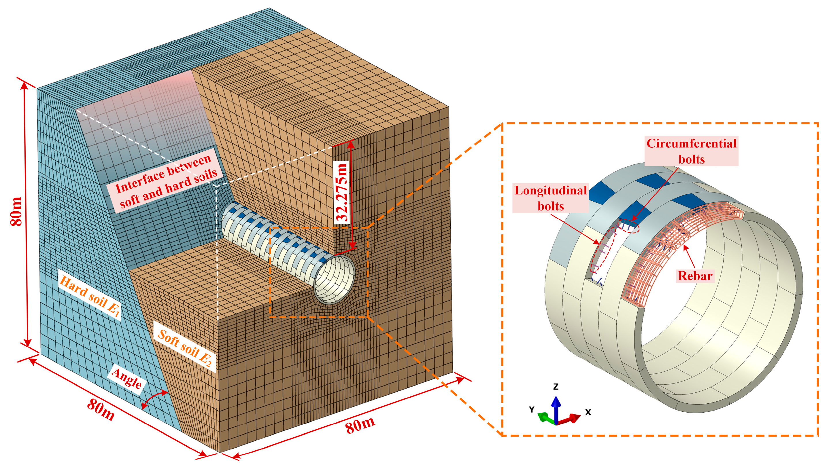
The Haizhu Bay Tunnel adopts C60-grade reinforced concrete segments, featuring an external diameter of 14.5 m and an internal diameter of 13.3 m. Each segment measures 0.6 m in thickness and 2 m in width. A complete segment ring consists of 10 segments: 1 key segment, 2 adjacent segments, and 7 standard segments. The central angles of the standard and adjacent segments are each three times that of the key segment. Segments are assembled using a staggered joint arrangement. The segmental connections utilize bolts with a strength grade of 8.8. For each ring, every longitudinal joint is secured with three circumferential inclined bolts of 36 mm in diameter, resulting in a total of 30 such bolts per ring. Meanwhile, circumferential joints between rings are connected by 56 longitudinal inclined bolts, each with a 30 mm diameter and inclined at an angle of 31.2° to the tunnel’s longitudinal axis. A schematic representation of the segmental lining structure layout for the Haizhu Bay Tunnel is presented in Figure 1.

3. Numerical Simulation

3.1. Establishment of Numerical Analysis Model

Based on the tunnel’s geometric characteristics, this study employs the finite element software ABAQUS (2021) to develop a numerical model of the shield tunnel section between EK1 + 520 and EK1 + 600, focusing on its behavior as it traverses heterogeneous soil layers. The numerical analysis model dimensions are 80 m in length, width, and height, including soft–hard soil bodies, 40 segment rings, connecting bolts, and reinforcement. Solid elements (C3D8R) are used to model the segments and surrounding soil, beam elements (B31) represent the bolts, and truss elements (T3D2) are employed to simulate the reinforcement. The tunnel model dimensions match the actual project, with a burial depth of 32.275 m. In the EK1 + 520 to EK1 + 600 section, the tunnel crosses heterogeneous soil layers at an angle of 60°, so the angle in the soil model is set to 60° to compare the longitudinal mechanical performance of the tunnel under different additional loads as it crosses soft–hard heterogeneous soil layers. An overview diagram of the numerical analysis model is shown in Figure 2.

3.2. Material Properties

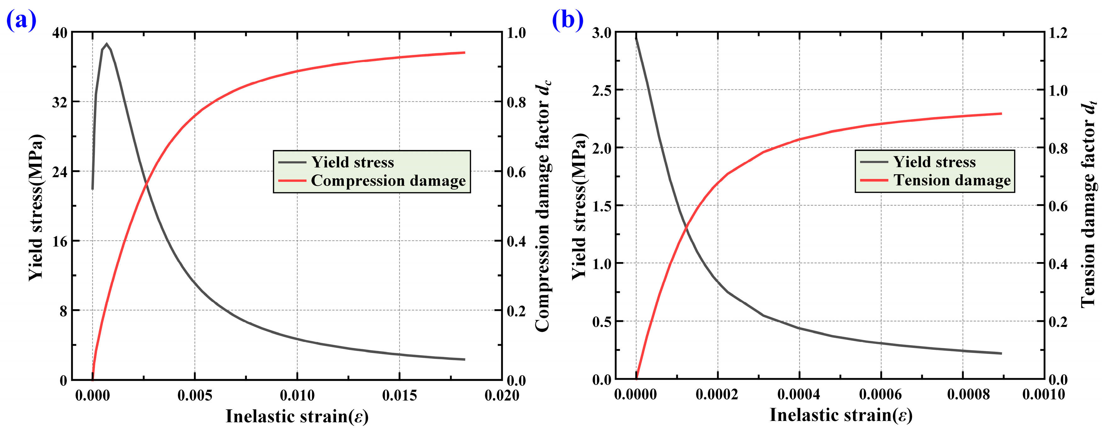
Concrete is modeled using ABAQUS’s built-in Concrete Damage Plasticity constitutive model. According to Code for Design of Concrete Structures (GB50010-2010) [26], the standard values of axial compressive strength, axial tensile strength, and elastic modulus of the concrete are determined, with the segmental lining using C60 concrete. The parameters used for the Concrete Damage Plasticity constitutive model are listed in Table 1. The concrete damage parameters are calculated using the equivalent energy method proposed by Sidoroff [27]. The relationship between damage variables and inelastic strain for C60 concrete under compression and tension [28,29] is shown in Figure 3.
The soft and hard soil layers are modeled using the Mohr–Coulomb constitutive model, with their mechanical properties detailed in Table 2. Both the bolts and reinforcement are simulated using a bilinear elastoplastic model, in which the elastic modulus drops to 1/100 of its original value upon reaching the yield stress. The connecting bolts are of grade 8.8, featuring a yield strength of 640 MPa and a tensile strength of 800 MPa. Their elastic modulus is 206 GPa, with a Poisson’s ratio of 0.3. The segments’ primary reinforcement is made from HRB400 steel, which has a yield strength of 400 MPa and a tensile strength of 540 MPa. It also has an elastic modulus of 210 GPa and a Poisson’s ratio of 0.3. For the hoop reinforcement in the segments, HPB300 steel is used, exhibiting a yield strength of 300 MPa and a tensile strength of 400 MPa. This material shares the same elastic modulus of 210 GPa and a Poisson’s ratio of 0.3.

3.3. Interaction and Boundary Conditions

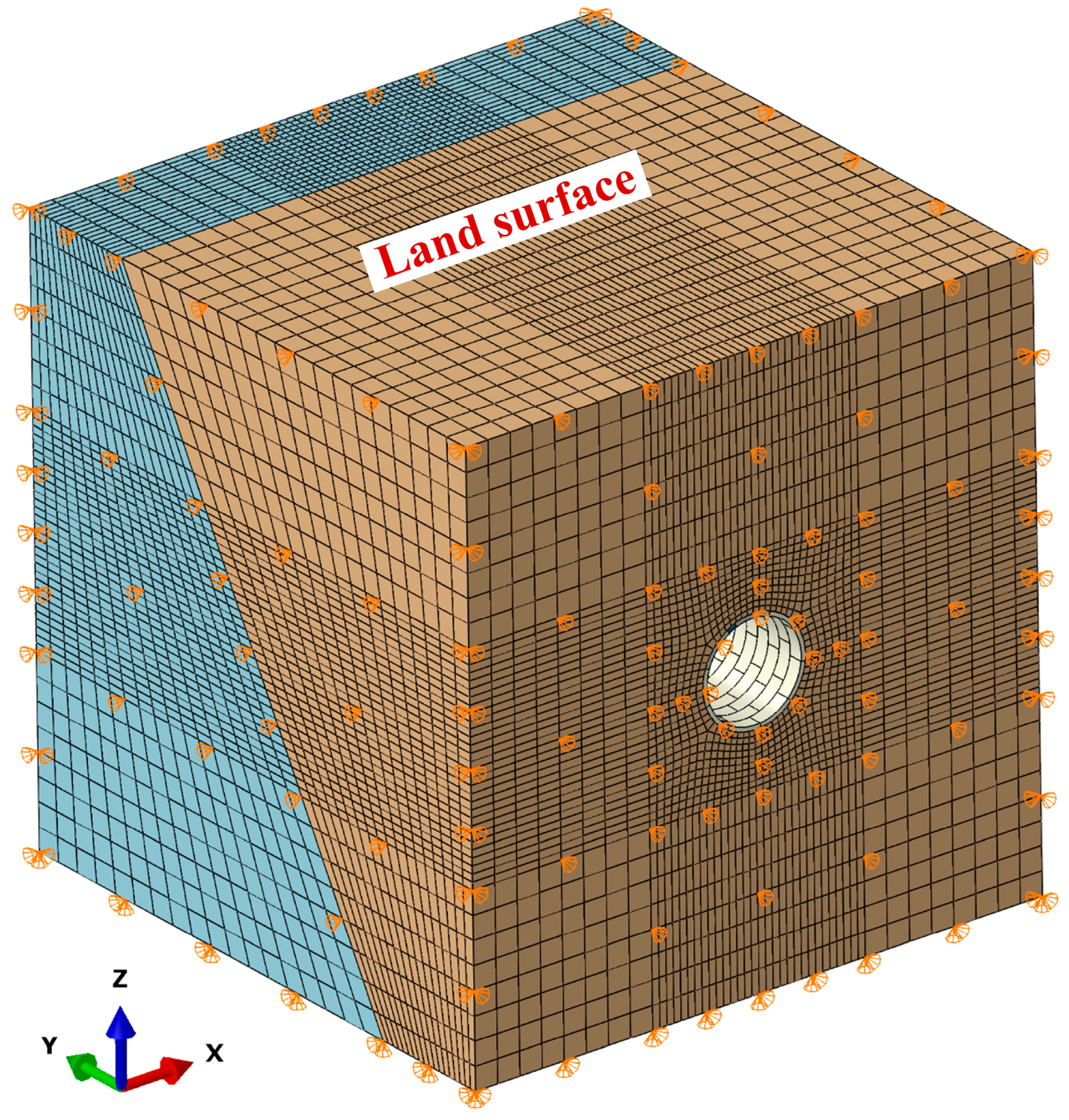
The interfaces between segment concrete elements are modeled as face-to-face contact, featuring a tangential friction coefficient of 0.55 and hard contact in the normal direction [28,30]. The soil–segment interfaces are also represented by face-to-face contact, incorporating a tangential friction coefficient of 0.4 and hard contact behavior normal to the surface. The longitudinal and circumferential bolts are embedded into the segment concrete at both ends using embedded interaction, and the reinforcement mesh is also fully embedded within the segments using embedded interaction [28,31]. Normal constraints are applied to all faces of the soil body, except for the ground surface. The boundary conditions are shown in Figure 4.

3.4. Loading Method and Conditions

The loading method of this numerical analysis model is shown in Figure 5. The entire loading process can be divided into two steps.
Step 1: As this study concentrates on the tunnel’s longitudinal mechanical behavior during operation, the excavation process is modeled using a one-step simulation approach. This involves activating the segments, applying longitudinal forces, and performing iterative calculations using the ODB import method in ABAQUS until the initial displacement is less than 10−4 mm.
Step 2: An additional load is applied at the surface, with the maximum load P set to 0.4 MPa. The load is incrementally applied in steps of 0.01 MPa by controlling the size of the load increment steps.
This numerical model primarily investigates the longitudinal mechanical performance of shield tunnels crossing soft–hard heterogeneous soil layers under different additional loads, while keeping the soil material properties unchanged. The specific calculation conditions of the numerical analysis model are detailed in Table 3.

4. Result Analysis

4.1. Vertical Displacement of Shield Tunnel

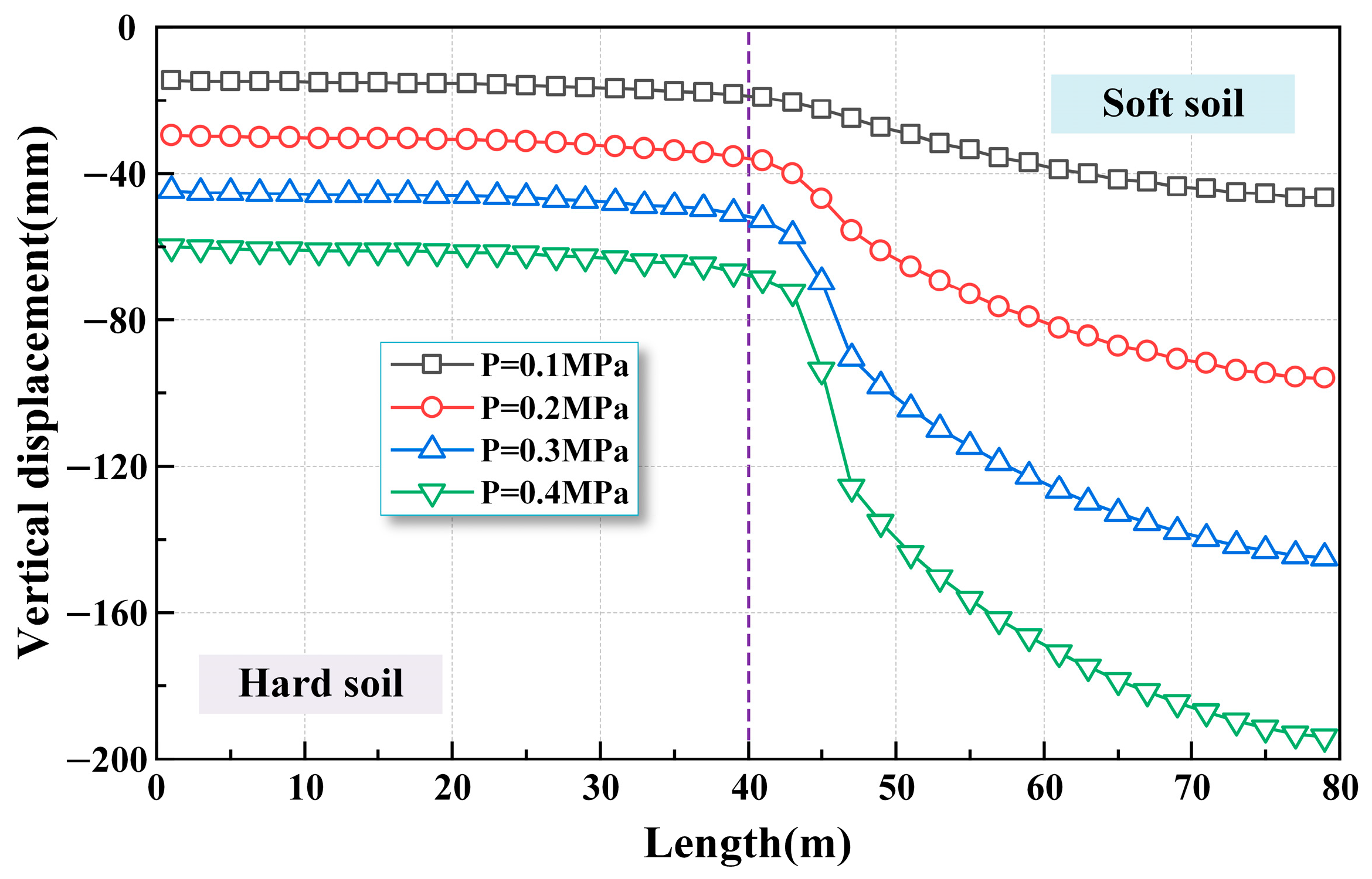
The vertical displacement distribution at the tunnel vault under varying additional loads P is extracted to analyze the longitudinal uneven deformation of shield tunnels through heterogeneous soil layers, as depicted in Figure 6.
Figure 6 illustrates that the tunnel undergoes notable longitudinal uneven deformation when subjected to additional loads within heterogeneous soil layers. The tunnel undergoes varying degrees of settlement in both soil types. On the side of the hard soil layer, vertical displacement is smaller, and the difference in settlement between adjacent rings is relatively minor. This is because the hard soil layer provides greater resistance. In contrast, the side with the soft soil layer experiences larger vertical displacements and more significant differences in settlement between adjacent rings. This is due to the tunnel in the soft soil layer acting like a cantilever beam, where the settlement is smaller closer to the interface between soft and hard soil layers and larger further away from it. The longitudinal uneven deformation of the tunnel is primarily concentrated on the side of the soft soil layer near the soft–hard interface, which is closely related to the angle of the heterogeneous soil layers. Additionally, as the additional load increases, this uneven settlement becomes more pronounced.

4.2. Deformation of Circumferential Joints

The uneven longitudinal settlement during the service life of the shield tunnel can cause notable deformation in the circumferential joints, which may compromise the overall structural safety of the tunnel. It is essential to monitor the circumferential joint deformations in a timely manner, particularly for shield tunnels crossing heterogeneous soil layers, where these deformations may be more pronounced. Therefore, the opening and dislocation of circumferential joints under different additional loads in shield tunnels crossing heterogeneous soil layers are extracted, with the distributions shown in Figure 7 and Figure 8, respectively.
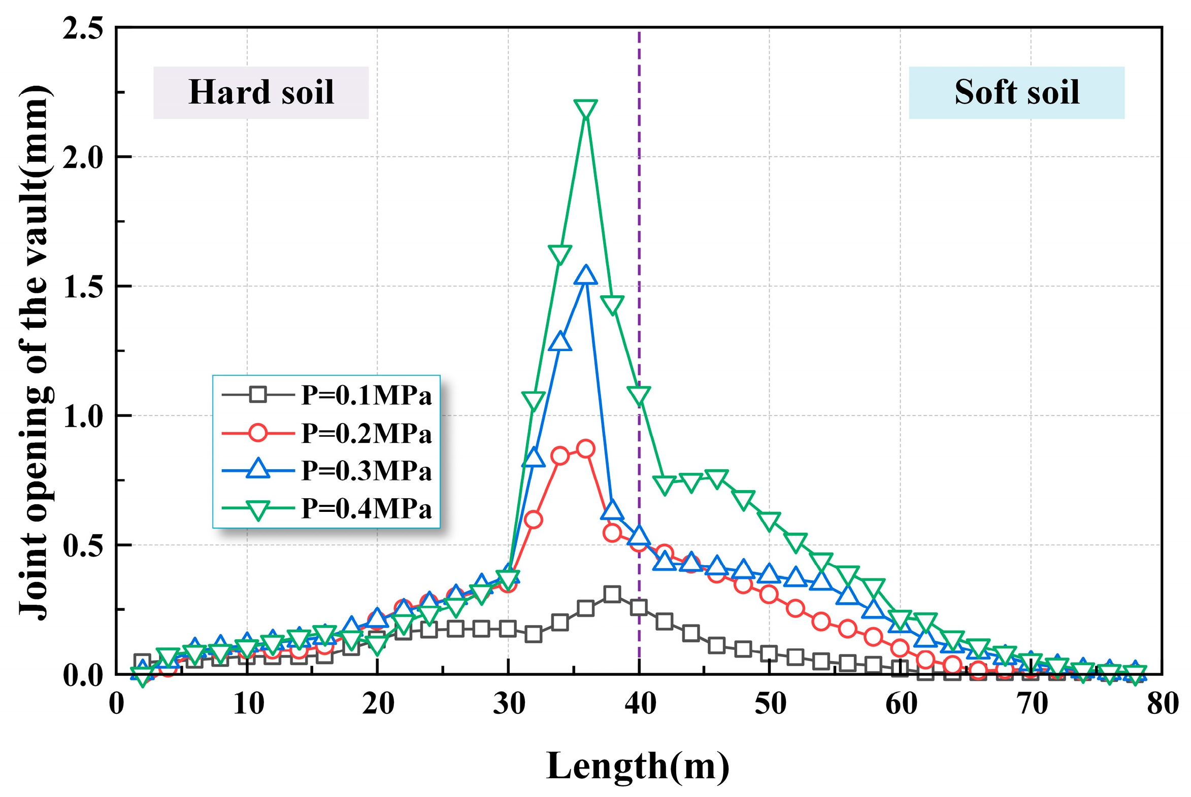
Figure 7 presents the variation pattern of vault opening in circumferential joints of shield tunnels passing through heterogeneous soil layers. As illustrated in Figure 7, when the tunnel is subjected to additional loads while crossing heterogeneous soil layers, the opening at the vault of the circumferential joints is maximized on the side of the circumferential joints closer to the hard soil layer. This is due to the angle of the heterogeneous interface. Under the influence of additional loads, the soil at the soft–hard interface undergoes uneven deformation, with greater settlement occurring in the soft soil layer compared to the hard soil layer. The vault of the shield tunnel is subjected to compressive, tensile, and shear forces from the soil. The segment rings slide with the soft soil layer, leading to stretching of the circumferential joints and a significant opening effect at the soft–hard interface. As the additional load increases, the opening of the circumferential joints progressively increases. Specifically, for additional loads of 0.1 MPa, 0.2 MPa, 0.3 MPa, and 0.4 MPa, the maximum opening of the circumferential joints is 0.31 mm, 0.87 mm, 1.53 mm, and 2.19 mm, respectively.
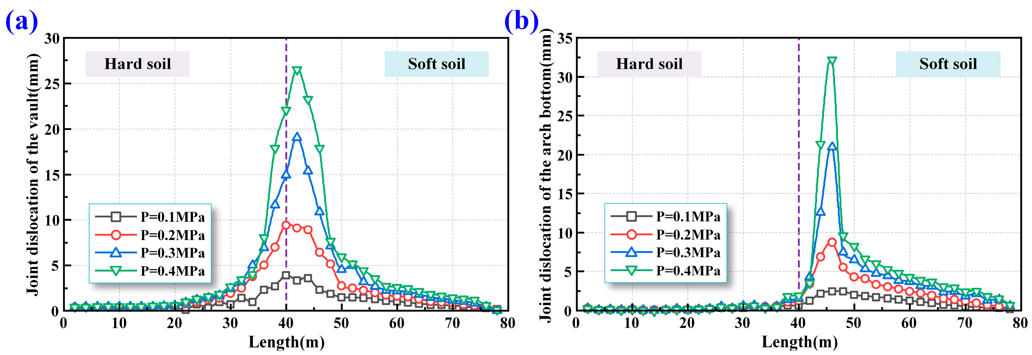
Figure 8 illustrates the dislocation distribution at the circumferential joints of shield tunnels traversing heterogeneous soil layers. Specifically, Figure 8a depicts the condition at the vault position, while Figure 8b shows the situation at the arch bottom position. In contrast to the maximum opening observed in circumferential joints, the greatest dislocation is found on the soft soil layer side at the interface between soft and hard soils. This phenomenon can be primarily attributed to the inclination of the heterogeneous interface. When the vault is supported by the hard soil layer, the dislocation remains relatively small; in contrast, when it is constrained by the soft soil layer, the dislocation becomes more significant. It is important to note that there is a difference in the magnitude and distribution of dislocation at the vault and arch bottom of the circumferential joints. The vault is directly subjected to compressive, tensile, and shear forces from the soil, resulting in a larger distribution range of dislocation at the vault, although its numerical value is smaller compared to the arch bottom. Dislocation at the arch bottom is more concentrated. Therefore, when the shield tunnel crosses heterogeneous soil layers, it is essential to monitor both the vault and arch bottom dislocation to prevent leakage and allow for timely reinforcement. As the additional load increases, the dislocation at the circumferential joints becomes more pronounced. Specifically, for additional loads of 0.1 MPa, 0.2 MPa, 0.3 MPa, and 0.4 MPa, the maximum dislocation at the vault is 3.87 mm, 9.40 mm, 19.05 mm, and 26.53 mm, respectively, and at the arch bottom is 2.45 mm, 8.73 mm, 20.96 mm, and 32.20 mm, respectively.
The significant contrast in joint opening and dislocation magnitudes across the soft–hard interface can be attributed to the combined effects of stratum inclination, stiffness contrast, and differential structural response. In this study, the interface between the soft and hard soils is inclined at approximately 60°, with soft soil overlying the hard soil. Under the action of surface surcharge, the tunnel experiences more pronounced overall settlement in the soft soil region due to its lower stiffness and weaker confinement, resulting in larger vertical differential deformation between segment rings. This induces greater shear deformation at the joints, which manifests as increased dislocation. On the hard soil side, the surrounding ground provides stronger constraint due to its higher stiffness, suppressing vertical differential settlement. As a result, inter-ring dislocation is minimal. However, as the soft side of the tunnel settles, it exerts a longitudinal tensile effect on the hard side, particularly near the tunnel crown. This tensile action promotes segment separation, leading to greater circumferential joint opening in the hard soil region. In summary, dislocation in soft soil is primarily governed by vertical shear-induced deformation, while joint opening in hard soil results from longitudinal tension. This deformation asymmetry underscores the complex soil–structure interaction when shield tunnels traverse inclined heterogeneous interfaces.

4.3. Vertical Convergence of Shield Tunnel

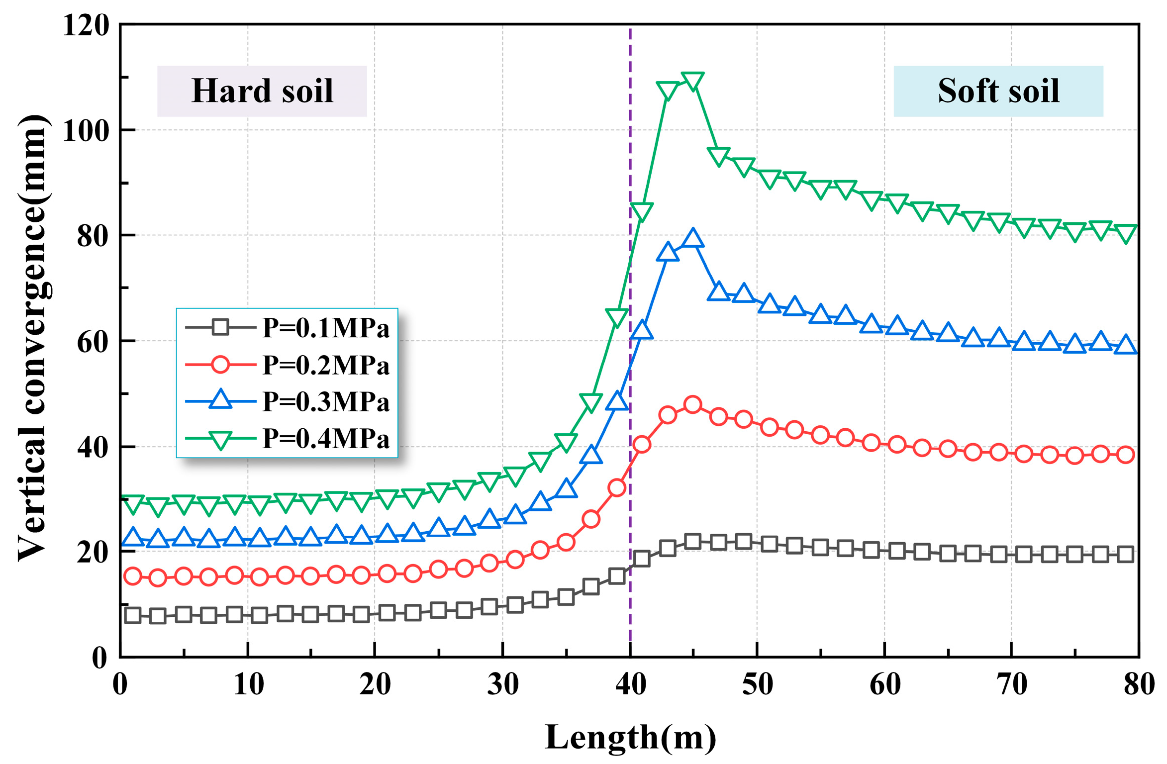
Under the action of overload, the tunnel will undergo significant transverse deformation. When the tunnel is subjected to overload in heterogeneous soil layers, the transverse deformation of the tunnel will exhibit noticeable differences due to the varying ground resistance of the soft and hard layers. To understand the transverse deformation of the tunnel under additional load in heterogeneous soil layers, the vertical convergence distribution of segment rings under different additional loads is extracted, as shown in Figure 9.
As shown in Figure 9, when the shield tunnel is exposed to additional loads in heterogeneous soil conditions, the vertical convergence of segment rings on the soft soil side is notably larger compared to that on the hard soil side. Furthermore, the vertical convergence is the largest on the soft soil side near the soft–hard interface. The primary reasons for the transverse deformation of the segment rings can be attributed to two points: first, the transverse deformation caused by surface settlement due to the additional load, which results in smaller transverse deformation of the segment rings on the hard soil side and greater transverse deformation on the soft soil side; second, the existence of a certain angle at the soft–hard interface, where the tunnel is situated in the soft soil layer over the hard soil layer near the interface, causing greater transverse deformation of the segment rings at this location. The maximum vertical convergence of the shield tunnel segment rings occurs at a position approximately 6–8 m from the soft–hard interface on the soft soil side, with the specific range depending on the angle of the soft–hard interface. This indicates that transverse deformation of the segment rings on the soft soil side near the soft–hard interface should be closely monitored, with the monitoring range determined based on the angle of the soft–hard interface. As the additional load increases, the transverse deformation of the segment rings becomes more pronounced, especially at the soft–hard interface. When the additional load P is 0.1 MPa, 0.2 MPa, 0.3 MPa, and 0.4 MPa, the maximum vertical convergence of the shield tunnel segment rings is 21.94 mm, 47.83 mm, 79.10 mm, and 109.67 mm, respectively.

4.4. Reinforcement and Bolt Stresses

The bolts are one of the primary components connecting the segment joints. To gain a comprehensive understanding of the stress distribution in the bolts under additional loading in heterogeneous soil layers, the stress contour of the bolts in the shield tunnel is extracted under a load of 0.4 MPa, as illustrated in Figure 10.
As depicted in Figure 10, when the tunnel is subjected to additional loads in a heterogeneous soil environment, the stress levels in the circumferential bolts are markedly lower than those observed in the longitudinal bolts. This is due to the more severe longitudinal uneven deformation of the tunnel. The maximum stress on the longitudinal bolts occurs at the upper bolts of the circumferential joints at the soft–hard interface, corresponding to the previously mentioned phenomenon of significant joint opening at this location.
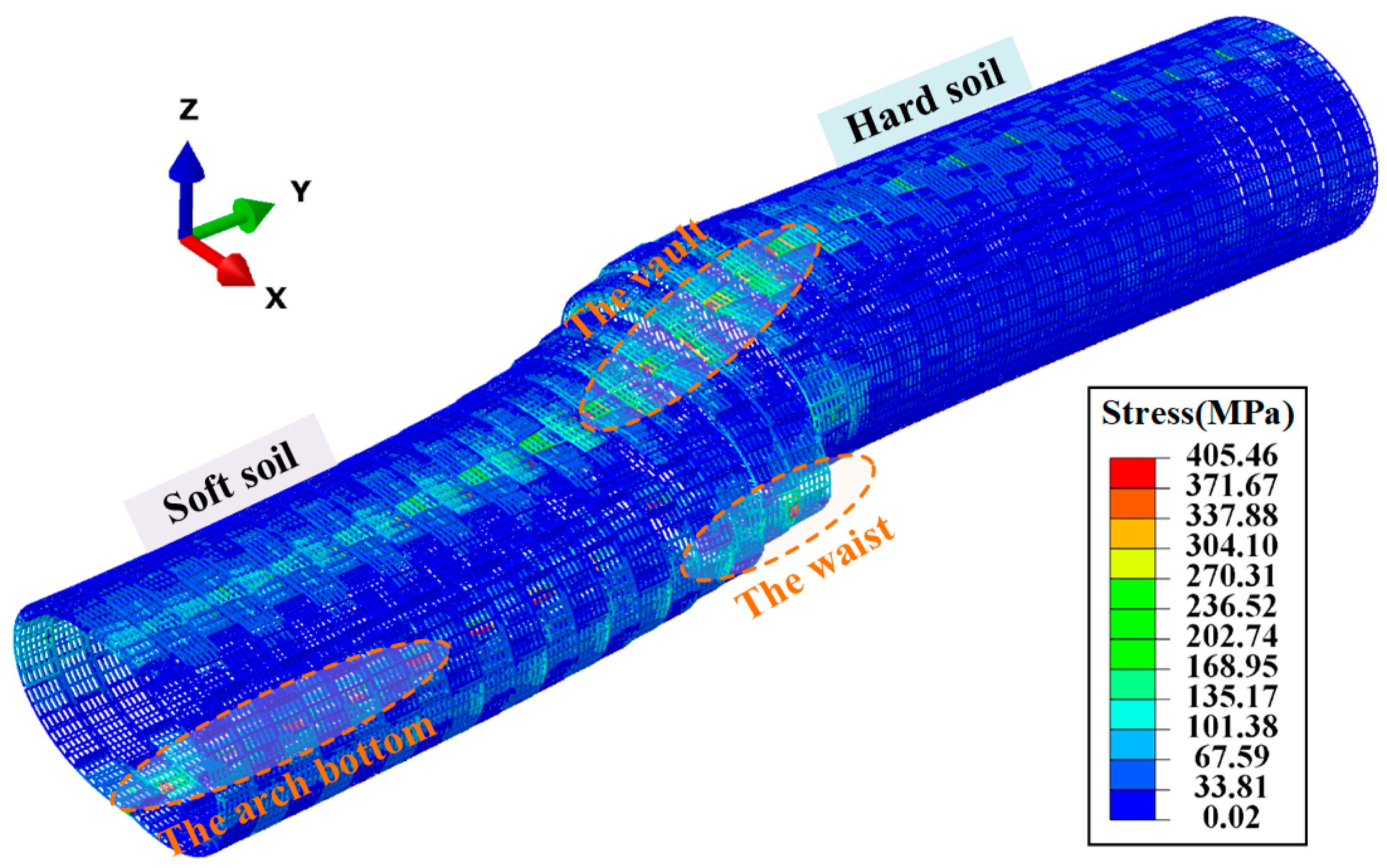
Figure 11 shows the stress cloud diagram of the reinforcement bars in the shield tunnel under an additional load of 0.4 MPa. From Figure 11, it can be observed that the inner reinforcement bars at the vault and arch bottom and the outer reinforcement bars at the arch waist are significantly stressed, with the maximum stress occurring on the inner reinforcement bars at the vault. This is because the segments at the top of the tunnel are the most deformed, leading to higher stress on the inner reinforcement bars at the vault. From the longitudinal distribution perspective, the stress on the reinforcement bars on the soft soil side is significantly greater than on the hard soil side, with the maximum stress occurring on the inner reinforcement bars at the vault of the segment ring on the soft soil side at the soft–hard interface. Overall, the stress distribution of the reinforcement bars shows a strong correlation with the transverse deformation of the segment rings. This is because when the transverse deformation of the segment rings is large, the lining structure is significantly stressed, leading to increased stress on the reinforcement bars.

4.5. Overall Lining Damage of Shield Tunnel

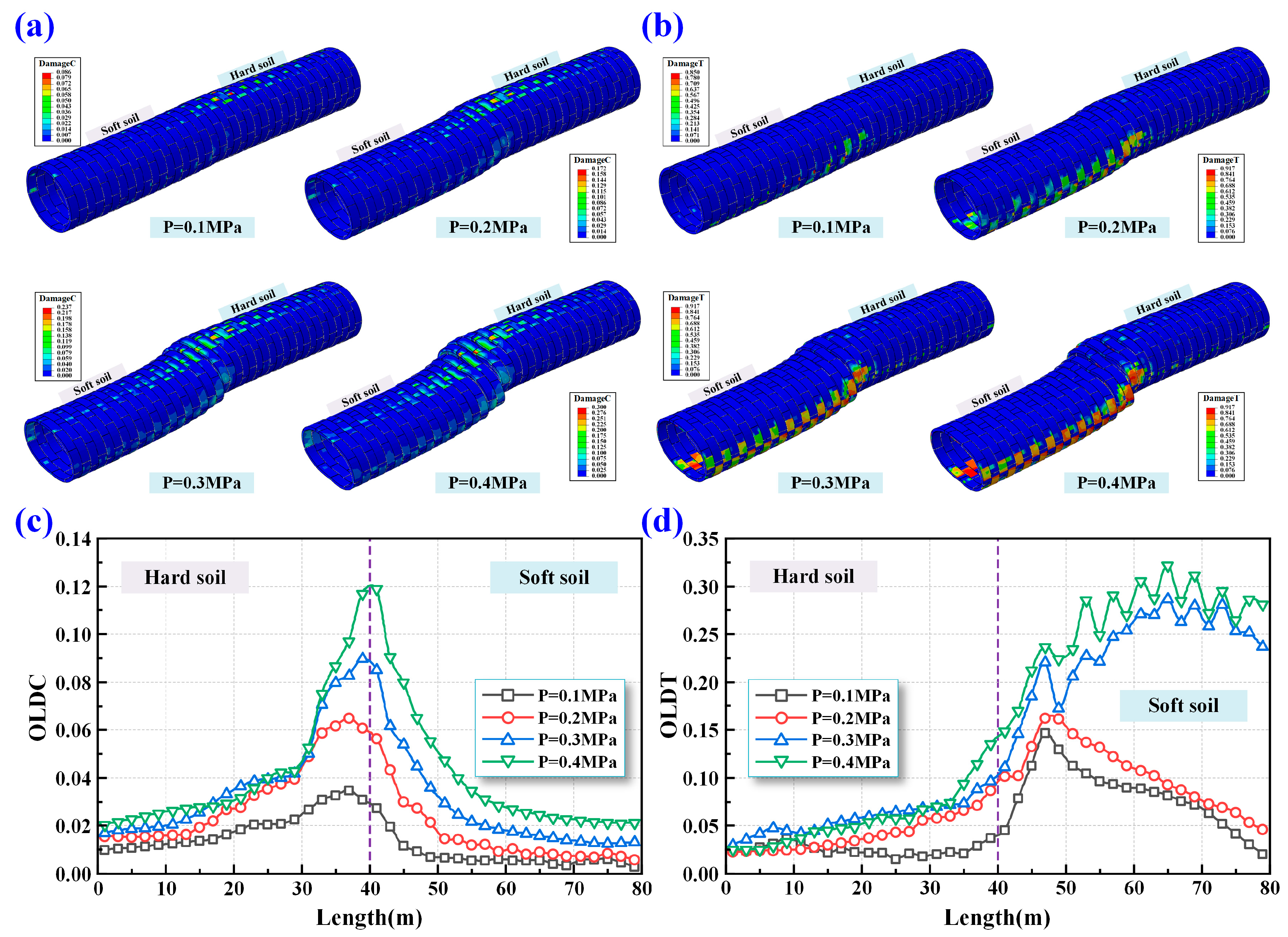
To assess the cross-sectional damage characteristics of the shield tunnel when traversing heterogeneous soil layers in a quantitative manner, this study adopts the tunnel lining damage index. The shield tunnel lining damage index is composed of two distinct parts: the Overall Lining Damage Index under Compression (OLDC) and the Overall Lining Damage Index under Tension (OLDT) [32]. These damage indices can be computed based on the equations presented in Equations (1) and (2). The overall lining damage index is derived from a weighted summation of the damage variables of all elements in the tunnel cross-section, with each weight determined by the ratio of the energy dissipated by an individual element to the total energy dissipated across all elements [33].
O L D C = i = 1 n d c i e E i e i = 1 n E i e 1
O L D T = i = 1 n d t i e E i e i = 1 n E i e 1
where d c i e and d t i e denote the compressive and tensile damage variables, respectively, of the i-th element, while E i e represents the total energy dissipated by that element, which includes both plastic dissipation energy and energy lost due to damage.
Figure 12 demonstrates the distribution of overall lining damage along the longitudinal axis of the shield tunnel when subjected to different levels of additional loads. It can be seen that the maximum compressive damage of the lining occurs at the interface between soft and hard soil layers, while the maximum tensile damage occurs on the soft soil side. With an increase in the additional load, the severity and spatial extent of both compressive and tensile damage in the tunnel lining cross-section become more pronounced. The increase in loading amplifies soil differential deformation, thereby strengthening the interaction between the tunnel lining and the surrounding ground. Consequently, compressive stresses concentrate at the soft–hard interface, where notable tensile damage occurs, especially on the soft soil side. The overall tensile damage distribution can be categorized into two patterns: when the additional load is 0.1 MPa and 0.2 MPa, the maximum tensile damage is located on the soft soil side near the interface, corresponding with the position of maximum vertical convergence of the segment rings. These findings indicate that transverse deformation of the segmental rings plays a key role in inducing tensile damage in the tunnel lining when crossing the soft–hard interface. Conversely, when the tunnel is situated entirely within the soft soil layer, the tensile damage diminishes due to the lower additional load, which results in reduced transverse deformation. When the additional load increases to 0.3 MPa and 0.4 MPa, the tunnel in the soft soil layer experiences significant transverse deformation, causing substantial tensile damage on the inner sides of the vault and arch bottom, as well as on the outer sides of the arch waist. This leads to continuous growth in overall tensile damage of the lining as the tunnel fully enters the soft soil layer. Notably, the tensile damage distribution curve exhibits significant fluctuations on the soft soil side, primarily due to the staggered assembly of the tunnel segment [34], resulting in inconsistent coordination and varying degrees of damage.

5. Influence of Key Parameters on Structural Behavior

A systematic parametric sensitivity investigation was performed to evaluate the influence of critical parameters on the structural behavior and damage evolution of shield tunnels subjected to additional loads in heterogeneous soil layers. The analysis mainly focused on the longitudinal thrust and the configuration of longitudinal connecting bolts, including bolt diameter, inclination angle, and quantity. The selected values are based on both engineering practices and the literature. Specifically, the longitudinal thrust (1 MPa, 2 MPa, and 3 MPa) reflects the range derived from the shield jacking force during construction and the residual stress during operation. Bolt diameters (30 mm to 48 mm) and inclination angles (20° to 50°) cover both conventional metro tunnels and large-diameter subsea tunnels. The number of bolts is referenced from typical configurations, including 16 bolts in metro tunnels and 56 in the Haizhu Bay Tunnel. The calculation cases used in the parametric analysis are summarized in Table 4.

5.1. Effects of Longitudinal Force

5.1.1. Deformation of Shield Tunnel

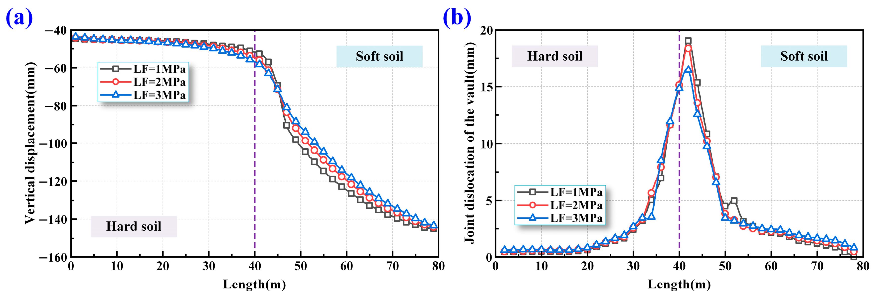
Figure 13 illustrates the deformation characteristics of a shield tunnel when passing through soft–hard heterogeneous soil layers under different longitudinal forces. Specifically, Figure 13a depicts the vertical displacement distribution, and Figure 13b shows the dislocation of circumferential joints. From Figure 13a, it is evident that as the longitudinal force increases, the vertical displacement on the soft soil side decreases, while the displacement on the hard soil side increases. This indicates that increasing the longitudinal force can effectively enhance the longitudinal integrity of the shield tunnel, significantly reducing vertical displacement. Figure 13b shows that with the increase in longitudinal force, the dislocation at the circumferential joints near the soft–hard interface can be effectively suppressed. When the longitudinal force increases from 1 MPa to 2 MPa, there is only a slight decrease in the dislocation of the circumferential joints, which is not significant. However, when the longitudinal force increases from 1 MPa to 3 MPa, the maximum dislocation at the circumferential joints decreases by 2.60 mm.

5.1.2. Overall Lining Damage of Shield Tunnel

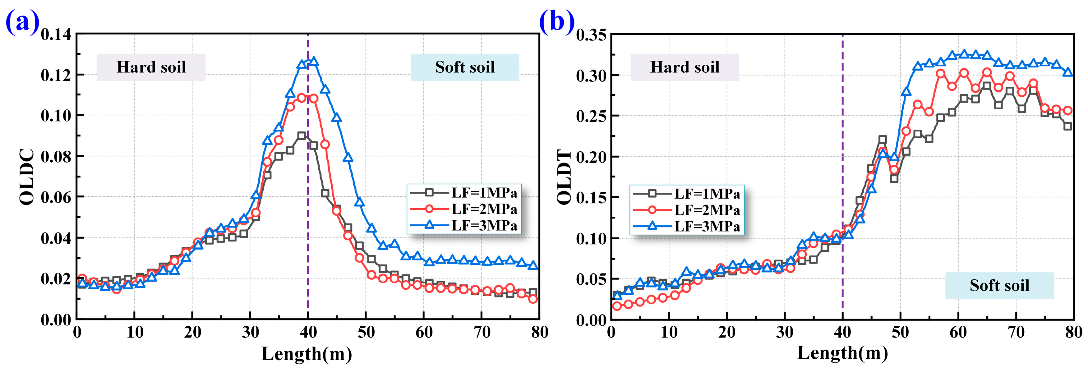
Figure 14 presents the damage patterns of the shield tunnel when crossing soft–hard heterogeneous soil layers under varying longitudinal forces. As shown in Figure 14a, both the severity and spatial extent of overall compressive damage to the lining increase with higher longitudinal forces. This is attributed to the enhanced longitudinal stiffness of the tunnel structure and the increased interaction between adjacent segmental rings. Consequently, the tunnel exhibits reduced deformability, and the interaction between the lining and the surrounding ground becomes more pronounced. This leads to a significant rise in compressive stress at the vault near the soft–hard interface, resulting in more extensive compressive damage to the lining.
As shown in Figure 14b, a reduction in overall tensile damage can be observed in segments 21 to 24 as the longitudinal force increases. This is primarily due to the enhanced interaction between segment rings and the increased transverse stiffness resulting from higher longitudinal forces. Under such conditions, the segments are less likely to undergo lateral deformation, thereby reducing the extent of tensile damage in the lining. Furthermore, under high longitudinal force, the tunnel structure exhibits improved overall integrity, with the segment rings deforming in a more coordinated manner. The segment rings in the soft soil layer experience more significant transverse deformation, leading to increased overall tensile damage to the lining. Conversely, under low longitudinal force conditions, insufficient ring constraints result in greater deformation of the ring bolts at the soft–hard interface, poorer coordination between segment rings, and smaller transverse deformation of the segments in the soft soil layer, leading to less overall tensile damage. The effectiveness of segment ring coordination can also be inferred from the stability of the overall compressive damage curve, which is more stable at a longitudinal force of 3 MPa compared to lower longitudinal forces.

5.2. Effects of Oblique Bolt Diameter

5.2.1. Deformation of Shield Tunnel

Figure 15 presents the deformation characteristics of the shield tunnel when crossing soft–hard heterogeneous soil layers under varying longitudinal bolt diameters. Figure 15a displays the vertical displacement, while Figure 15b illustrates the dislocation at the circumferential joints. As shown in Figure 15a, an increase in bolt diameter results in a slight reduction in vertical displacement on the soft soil side and a minor increase on the hard soil side. This suggests that increasing the bolt diameter has a limited effect on mitigating overall tunnel settlement. In Figure 15b, it is evident that increasing the bolt diameter effectively mitigates the circumferential joint dislocation at the soft–hard interface. When the longitudinal bolt diameter increases from 30 mm to 36 mm, the circumferential joint dislocation decreases significantly by 3.18 mm. However, further increasing the bolt diameter shows diminishing returns in reducing circumferential joint dislocation. This suggests that, in the design of longitudinal bolts for shield tunnels, both the functionality and economic aspects should be considered to select an appropriate bolt diameter.

5.2.2. Overall Lining Damage of Shield Tunnel

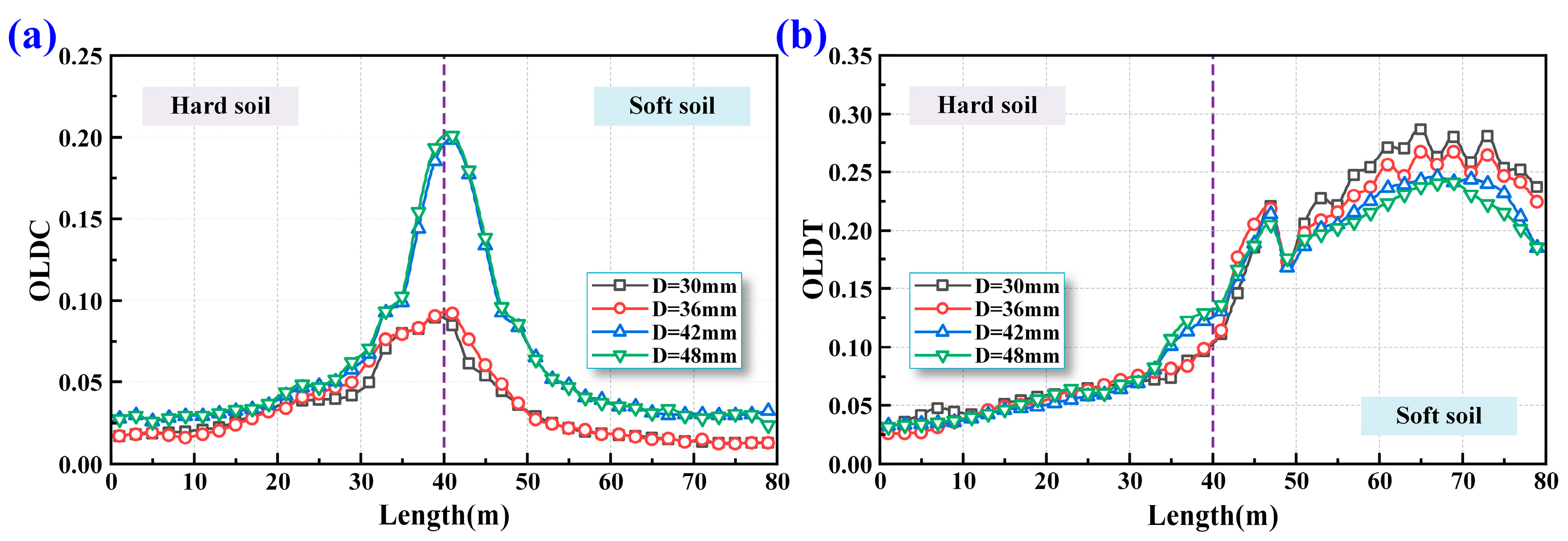
Figure 16 illustrates the damage distribution of shield tunnels traversing heterogeneous soil layers with varying longitudinal bolt diameters. As shown in Figure 16a, increasing the diameter of longitudinal bolts results in a higher degree and broader range of compressive damage to the lining. This phenomenon is attributed to the fact that increasing the bolt diameter enhances the longitudinal stiffness of the tunnel structure, thereby intensifying the interaction between the lining and the surrounding ground. As a result, compressive stress at the vault near the heterogeneous interface increases significantly, leading to a more pronounced overall compressive damage in the lining.
Figure 16b shows that the overall tensile damage in the lining gradually decreases with an increase in the diameter of the longitudinal bolts. This is due to the enhanced longitudinal stiffness of the tunnel structure, which reduces the lateral deformation of the segments and, consequently, mitigates the overall tensile damage. This trend highlights the coupled relationship between transverse and longitudinal deformation mechanisms in the shield tunnel.

5.3. Effects of Inclination Angle of Oblique Bolt

5.3.1. Deformation of Shield Tunnel

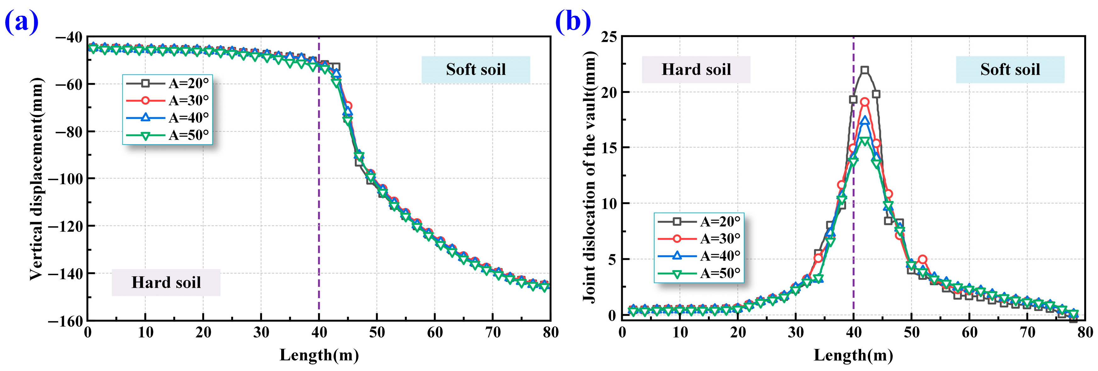
Figure 17 depicts the influence of longitudinal bolt inclination on the deformation characteristics of the shield tunnel as it crosses through heterogeneous soft–hard soil layers. Figure 17a shows that as the inclination angle of the longitudinal bolts increases, the vertical displacement of the tunnel on the soft soil side slightly decreases, while on the hard soil side it slightly increases. These results indicate that variations in the longitudinal bolt inclination have little effect on mitigating vertical displacement of the tunnel structure. Figure 17b demonstrates that increasing the inclination angle of the longitudinal bolts effectively suppresses the circumferential joint dislocation at the soft–hard interface. When the bolt inclination angle increases from 20° to 50°, the maximum joint dislocation decreases by 2.89 mm, 4.61 mm, and 6.28 mm, respectively. This shows that a higher bolt inclination angle effectively reduces the circumferential joint dislocation by enhancing the tensile resistance of the longitudinal bolts against the shear forces between segments. However, this adjustment may also increase the risk of the circumferential joint opening deformation. Therefore, in designing longitudinal bolts for shield tunnels, it is crucial to balance the ability of the bolts to prevent joint opening and dislocation by selecting an appropriate bolt inclination angle.

5.3.2. Overall Lining Damage of Shield Tunnel

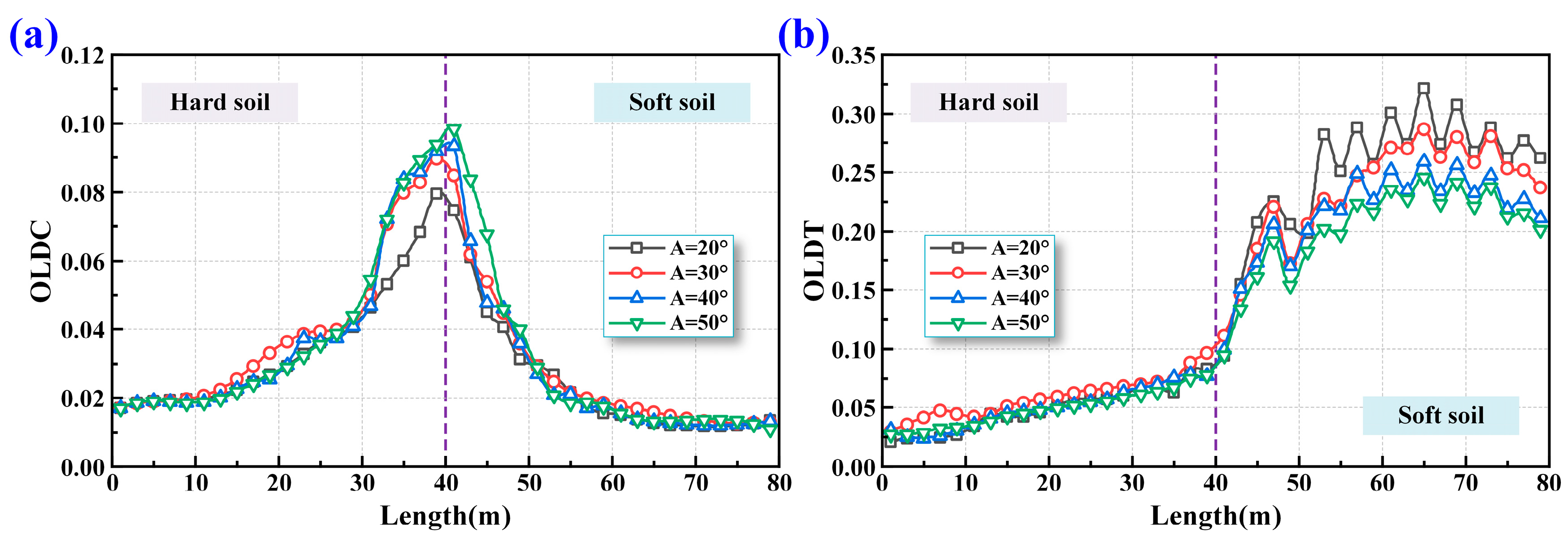
Figure 18 presents the overall lining tensile/compressive damages along the tunnel’s longitudinal direction when crossing heterogeneous soil layers under varying inclination angles of longitudinal bolts. As shown in Figure 18a, both the severity and spatial extent of overall compressive damage to the lining increase with higher bolt inclination angles. This is because a higher bolt inclination angle enhances the longitudinal shear stiffness of the tunnel, making it less prone to longitudinal shear deformation. Consequently, the enhanced interaction between the tunnel lining and the surrounding ground leads to a notable increase in compressive stress at the tunnel vault situated at the soft–hard boundary. This heightened stress concentration significantly intensifies the overall compressive damage sustained by the lining.
Figure 18b shows that the overall tensile damage in the lining gradually decreases as the inclination angle of the longitudinal bolts increases. This is attributed to the enhanced restraint provided by adjacent segment rings during transverse deformation, which helps mitigate tensile damage. Notably, with smaller bolt inclination angles, the tensile damage curve on the soft soil side exhibits greater fluctuations, indicating that larger inclination angles promote a more tightly integrated connection between adjacent segment rings.

5.4. Effects of the Number of Oblique Bolts

5.4.1. Deformation of Shield Tunnel

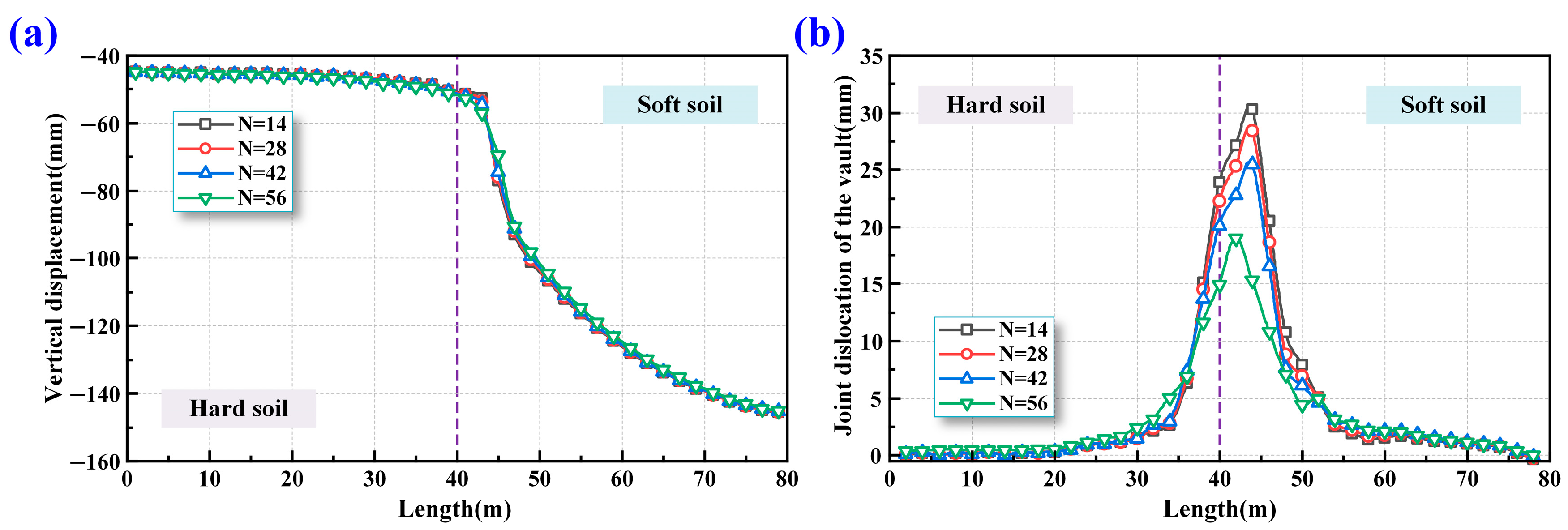
Figure 19 illustrates the deformation characteristics of a shield tunnel crossing through soft and hard soil layers under different numbers of longitudinal bolts. As shown in Figure 19a, an increase in the number of longitudinal bolts leads to a slight reduction in vertical displacement on the soft soil side and a minor increase on the hard soil side, indicating a minimal effect on overall settlement reduction. Figure 19b highlights that increasing the number of longitudinal bolts significantly reduces the dislocation of circumferential joints at the interface between soft and hard soil layers. Specifically, when the number of longitudinal bolts increases from 14 to 56, the maximum joint dislocation decreases by 1.93 mm, 4.85 mm, and 11.25 mm, respectively, demonstrating a substantial improvement in joint stability.

5.4.2. Overall Lining Damage of Shield Tunnel

Figure 20 displays the damage patterns of the shield tunnel as it traverses soft–hard soil layers under different quantities of longitudinal bolts. According to Figure 20a, both the range and intensity of compressive damage in the lining rise with an increasing number of bolts. This is primarily because more longitudinal bolts improve the structural rigidity along the tunnel axis, thereby strengthening the interaction between the lining and the surrounding ground. As a result, the compressive stress at the tunnel vault near the interface becomes more concentrated, which exacerbates the overall compressive damage.
Figure 20b shows that increasing the number of longitudinal bolts leads to a reduction in overall tensile damage to the lining. This decrease is attributed to the enhanced longitudinal stiffness provided by more bolts, which minimizes lateral deformation of the segments and consequently reduces tensile damage. This finding underscores the interplay between the transverse and longitudinal behaviors of the shield tunnel.

6. Discussion

Although this study provides a systematic analysis of the longitudinal mechanical response of shield tunnels crossing heterogeneous strata, several limitations remain. First, to focus on the influence of structural parameters on deformation and failure, the geological stratification was idealized, without modeling the transitional zone at the soft–hard interface or introducing an explicit contact surface. This simplification may lead to deviations in the stress transfer simulation between the tunnel and surrounding ground. Second, this study assumed a fixed interface inclination angle as a representative condition, without exploring the variation in mechanical responses under different inclination scenarios. This simplification may limit the generalizability of the conclusions. Future re-search will extend the investigation to include varying interface geometries and assess the influence of inclination on structural stress distribution and failure modes. Third, geotechnical parameters exhibit high uncertainty. Although some sensitivity analyses were conducted, the coupled effects among parameters were not fully addressed. Moreover, the applicability of the results is primarily constrained to shield tunnels with clear soft–hard transitions and typical segmental designs; for more complex geological settings, further calibration with site-specific conditions is necessary. Future work will incorporate contact interface modeling between soil and structure, broaden the parametric scope, and validate the numerical model using theoretical formulations and field monitoring data to enhance its engineering relevance.

7. Conclusions

This study is based on the Haizhu Bay shield tunnel project, which traverses complex soft–hard heterogeneous strata. A refined three-dimensional numerical model was established incorporating segment joints and bolt connections to simulate the longitudinal mechanical response and damage mechanisms under operational longitudinal forces and additional surface loads. The analysis focused on differential settlement, structural deformation, and damage distribution near the soft–hard interface. A parametric sensitivity study was also conducted to investigate the influence of longitudinal thrust and bolt parameters on tunnel stiffness, joint behavior, and damage evolution. The main conclusions are as follows:
(1)
At the soft–hard interface, significant differential settlement occurs due to stiffness contrast. Joint opening is prominent on the hard soil side, while joint dislocation dominates on the soft soil side. Although the dislocation extent is larger at the vault, the maximum dislocation magnitude appears at the arch bottom.
(2)
Transverse deformation is more constrained in hard soil and more pronounced in soft soil near the interface. Compressive damage mainly concentrates at the interface, while tensile damage is more significant in soft soil zones. Fluctuations in tensile damage are linked to uneven interaction between segment rings.
(3)
Increasing longitudinal force enhances structural stiffness and reduces longitudinal deformation and joint dislocation but also intensifies compressive damage at the soft-hard interface and tensile damage in soft soils.
(4)
Enhancing bolt diameter, inclination angle, or quantity slightly reduces longitudinal deformation but more significantly improves joint coordination. In particular, bolt inclination is effective in limiting joint dislocation and transverse deformation.
(5)
The extent of compressive and tensile damage is closely related to longitudinal and transverse stiffness, respectively. Optimizing longitudinal force and bolt configuration is essential for improving tunnel integrity and minimizing damage in variable ground conditions.

Author Contributions

Conceptualization, X.X. and Q.R.; methodology, X.X.; software, Q.Z. and X.P.; validation, Y.X., B.W. and L.W.; formal analysis, B.W.; investigation, Y.X.; data curation, X.X.; writing—original draft preparation, X.X. and Q.Z.; writing—review and editing, Q.R.; visualization, X.X.; supervision, Q.R., Y.X. and B.W. All authors have read and agreed to the published version of the manuscript.

Funding

This research received no external funding.

Data Availability Statement

The original contributions presented in this study are included in this article, further inquiries can be directed to the corresponding author.

Conflicts of Interest

Authors Xiaojie Xue, Qingcheng Zeng, Xushu Peng and Luxiang Wu are employed by the Guangzhou Expressway Co., Ltd. Authors Xiaojie Xue, Qingcheng Zeng, Xushu Peng and Luxiang Wu are employed by the Guangzhou Haizhu Bay Construction Co., Ltd. Author Bohan Wu is employed by the PowerChina HuaDong Engineering Co., Ltd. The remaining authors declare that the research was conducted in the absence of any commercial or financial relationships that could be construed as a potential conflict of interest.

References

  1. Berthoz, N.; Branque, D.; Subrin, D.; Wong, H.; Humbert, E. Face Failure in Homogeneous and Stratified Soft Ground: Theoretical and Experimental Approaches on 1g EPBS Reduced Scale Model. Tunn. Undergr. Space Technol. 2012, 30, 25–37. [Google Scholar] [CrossRef]
  2. Zhao, K.; Bonini, M.; Debernardi, D.; Janutolo, M.; Barla, G.; Chen, G. Computational Modelling of the Mechanised Excavation of Deep Tunnels in Weak Rock. Comput. Geotech. 2015, 66, 158–171. [Google Scholar] [CrossRef]
  3. He, C.; Feng, K.; Fang, Y.; Jiang, Y. Surface Settlement Caused by Twin-Parallel Shield Tunnelling in Sandy Cobble Strata. J. Zhejiang Univ. Sci. A 2012, 13, 858–869. [Google Scholar] [CrossRef]
  4. Shen, S.-L.; Wu, H.-N.; Cui, Y.-J.; Yin, Z.-Y. Long-Term Settlement Behaviour of Metro Tunnels in the Soft Deposits of Shanghai. Tunn. Undergr. Space Technol. 2014, 40, 309–323. [Google Scholar] [CrossRef]
  5. Wu, H.-N.; Shen, S.-L.; Chen, R.-P.; Zhou, A. Three-Dimensional Numerical Modelling on Localised Leakage in Segmental Lining of Shield Tunnels. Comput. Geotech. 2020, 122, 103549. [Google Scholar] [CrossRef]
  6. Koizumi, A.; Murakami, H.; Nishino, K. Study on the Analytical Model of Shield Tunnel in Longitudinal Direction. Proc. Jpn. Soc. Civ. Eng. 1988, 394, 79–88. [Google Scholar] [CrossRef]
  7. Shiba, Y.; Kawashima, K.; Obinata, N.; Kano, T. An Evaluation Method of Longitudinal Stiffness of Shield Tunnel Linings for Application to Seismic Response Analyses. Proc. Jpn. Soc. Civ. Eng. 1988, 398, 319–327. [Google Scholar] [CrossRef]
  8. Liang, F.; Jiang, Z.; Yuan, Q.; Li, L.; Wang, R. Time-Dependent Longitudinal Responses of a Shield Tunnel Induced by Surcharge Load: Theoretical Prediction and Analysis. Undergr. Space 2024, 14, 219–238. [Google Scholar] [CrossRef]
  9. Liang, R.; Xia, T.; Huang, M.; Lin, C. Simplified Analytical Method for Evaluating the Effects of Adjacent Excavation on Shield Tunnel Considering the Shearing Effect. Comput. Geotech. 2017, 81, 167–187. [Google Scholar] [CrossRef]
  10. Li, X.; Zhou, X.; Hong, B.; Zhu, H. Experimental and Analytical Study on Longitudinal Bending Behavior of Shield Tunnel Subjected to Longitudinal Axial Forces. Tunn. Undergr. Space Technol. 2019, 86, 128–137. [Google Scholar] [CrossRef]
  11. Liu, T.; Zhang, S.; Tang, Y.; Ye, Z. Experimental Study on the Longitudinal Mechanical Behavior of Shield Tunnel in Soft-Hard Uneven Strata and the Reinforcement Effect of Longitudinal Channel Steel. KSCE J. Civ. Eng. 2024, 28, 409–427. [Google Scholar] [CrossRef]
  12. Huang, D.; Jiang, H.; Xu, C.; Li, X.; Zhan, T. Analytical Algorithm of Longitudinal Bending Stiffness of Shield Tunnel Considering Longitudinal Residual Jacking Force. Tunn. Undergr. Space Technol. 2023, 137, 105146. [Google Scholar] [CrossRef]
  13. Ding, Z.; Zhang, X.; He, S.-H.; Qi, Y.-J.; Lin, C.-G. Experimental and Theoretical Study on Longitudinal Deformation and Internal Force of Shield Tunnel under Surcharge. Tunn. Undergr. Space Technol. 2024, 144, 105506. [Google Scholar] [CrossRef]
  14. Gou, Y.; Huang, Q.; Jia, S.; Yang, X.; Zhang, Y. Navigating the Depths: Experimental Study on the Influence of Ground Fissures on Metro Shield Tunnels Considering Different Intersection Angles. Eng. Fail. Anal. 2024, 162, 108425. [Google Scholar] [CrossRef]
  15. Wang, Z.; Wang, L.; Li, L.; Wang, J. Failure Mechanism of Tunnel Lining Joints and Bolts with Uneven Longitudinal Ground Settlement. Tunn. Undergr. Space Technol. 2014, 40, 300–308. [Google Scholar] [CrossRef]
  16. Shi, C.; Cao, C.; Lei, M.; Peng, L.; Ai, H. Effects of Lateral Unloading on the Mechanical and Deformation Performance of Shield Tunnel Segment Joints. Tunn. Undergr. Space Technol. 2016, 51, 175–188. [Google Scholar] [CrossRef]
  17. Huang, Z.; Zhang, H.; Fu, H.; Ma, S.; Liu, Y. Deformation Response Induced by Surcharge Loading above Shallow Shield Tunnels in Soft Soil. KSCE J. Civ. Eng. 2020, 24, 2533–2545. [Google Scholar] [CrossRef]
  18. Liu, J.; Shi, C.; Wang, Z.; Lei, M.; Zhao, D.; Cao, C. Damage Mechanism Modelling of Shield Tunnel with Longitudinal Differential Deformation Based on Elastoplastic Damage Model. Tunn. Undergr. Space Technol. 2021, 113, 103952. [Google Scholar] [CrossRef]
  19. Liu, J.; Shi, C.; Lei, M.; Wang, Z.; Cao, C.; Lin, Y. A Study on Damage Mechanism Modelling of Shield Tunnel under Unloading Based on Damage-Plasticity Model of Concrete. Eng. Fail. Anal. 2021, 123, 105261. [Google Scholar] [CrossRef]
  20. Wang, Q.; Geng, P.; Li, P.; He, D.; Shen, H. Failure Analysis of Circumferential Joints and Preferable Bolt Form of Shield Tunnel under Normal Fault Dislocation. Tunn. Undergr. Space Technol. 2024, 146, 105648. [Google Scholar] [CrossRef]
  21. Hu, J.; Chai, S.; Wang, H.; Chen, J.; Fu, X.; Zhou, Y. Longitudinal Mechanical Properties of Shield Tunnels Crossing Soft and Hard Mutation Strata. Int. J. Geomech. 2023, 23, 04023225. [Google Scholar] [CrossRef]
  22. Galván, A.; Peña, F.; Moreno-Martínez, J.Y. Effect of TBM Advance in the Structural Response of Segmental Tunnel Lining. Int. J. Geomech. 2017, 17, 04017056. [Google Scholar] [CrossRef]
  23. Guo, W.; Feng, K.; Lu, X.; Qi, M.; Liu, X.; Fang, Y.; He, C.; Xiao, M. Model Test Investigation on the Longitudinal Mechanical Property of Shield Tunnels Considering Internal Structure. Tunn. Undergr. Space Technol. 2023, 140, 105293. [Google Scholar] [CrossRef]
  24. Guo, W.; Feng, K.; Zhou, Y.; Lu, X.; Qi, M.; He, C.; Xiao, M. Experimental and Numerical Investigation on the Shear Behavior and Damage Mechanism of Segmental Joint under Compression-Shear Load. Tunn. Undergr. Space Technol. 2023, 139, 105238. [Google Scholar] [CrossRef]
  25. Guo, W.; Feng, K.; Zhou, Y.; Cao, X.; Zhao, L. Investigation on the Shear Performance of Circumferential Joints of Segments in Super-large Cross-section Shield Tunnels. Struct. Concr. 2023, 24, 4978–4992. [Google Scholar] [CrossRef]
  26. GB50010-2010; Code for Design of Concrete Structures. China Architecture & Building Press: Beijing, China, 2015.
  27. Sidoroff, F. Description of Anisotropic Damage Application to Elasticity. In Physical Non-Linearities in Structural Analysis; Hult, J., Lemaitre, J., Eds.; Springer: Berlin/Heidelberg, Germany, 1981; pp. 237–244. [Google Scholar]
  28. Huang, Z.; Zhang, C.-L.; Ma, S.-K.; Zhang, J.-B.; Zhu, Q.-X. Study of the Mechanical Behaviour and Damage Characteristics of Three New Types of Joints for Fabricated Rectangular Tunnels Using a Numerical Approach. Tunn. Undergr. Space Technol. 2021, 118, 104184. [Google Scholar] [CrossRef]
  29. Yan, G.; Shen, Y.; Gao, B.; Zheng, Q.; Fan, K.; Huang, H. Damage Evolution of Tunnel Lining with Steel Reinforced Rubber Joints under Normal Faulting: An Experimental and Numerical Investigation. Tunn. Undergr. Space Technol. 2020, 97, 103223. [Google Scholar] [CrossRef]
  30. Zhang, L.; Feng, K.; Xu, P.; He, C.; Zhang, H. Refined Three-dimensional Numerical Model for Segmental Joint and Its Application. Struct. Concr. 2020, 21, 1612–1624. [Google Scholar] [CrossRef]
  31. Wu, H.-N.; Chen, S.; Chen, R.-P.; Cheng, H.-Z.; Feng, D.-L. Deformation Behaviors and Failure Mechanism of Segmental RC Lining under Unloading Condition. Tunn. Undergr. Space Technol. 2022, 130, 104687. [Google Scholar] [CrossRef]
  32. Chen, Z.; Wei, J. Correlation between Ground Motion Parameters and Lining Damage Indices for Mountain Tunnels. Nat. Hazards 2013, 65, 1683–1702. [Google Scholar] [CrossRef]
  33. Park, Y.; Ang, A.H.-S. Mechanistic Seismic Damage Model for Reinforced Concrete. J. Struct. Eng. 1985, 111, 722–739. [Google Scholar] [CrossRef]
  34. Feng, K.; He, C.; Fang, Y.; Jiang, Y. Study on the Mechanical Behavior of Lining Structure for Underwater Shield Tunnel of High-Speed Railway. Adv. Struct. Eng. 2013, 16, 1381–1399. [Google Scholar] [CrossRef]
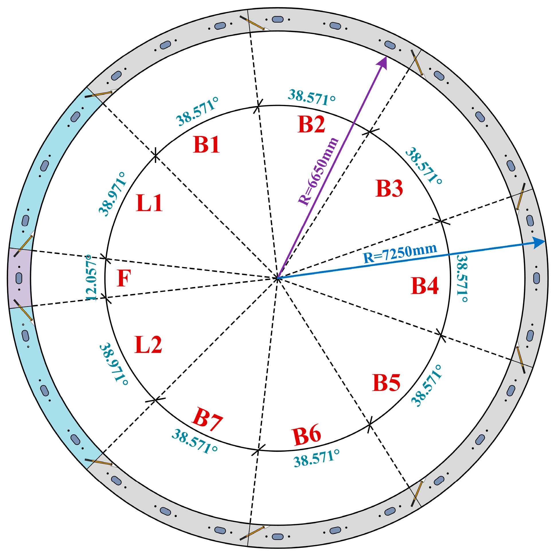
Figure 1. Schematic representation of the segmental lining structure.
Buildings 15 03417 g001
Figure 2. Overview diagram of the numerical analysis model.
Buildings 15 03417 g002
Figure 3. Stress-inelastic strain and damage factor-inelastic strain relationships for concrete: (a) compression behavior; (b) tension behavior.
Buildings 15 03417 g003
Figure 4. Boundary conditions applied in the numerical analysis model.
Buildings 15 03417 g004
Figure 5. Schematic diagram of model loading method.
Buildings 15 03417 g005
Figure 6. Vertical displacement of shield tunnel.
Buildings 15 03417 g006
Figure 7. Circumferential joint opening in a shield tunnel.
Buildings 15 03417 g007
Figure 8. Circumferential joint dislocation in a shield tunnel: (a) dislocation at the vault; (b) dislocation at the arch bottom.
Buildings 15 03417 g008
Figure 9. Vertical convergence deformation of the shield tunnel.
Buildings 15 03417 g009
Figure 10. Bolt stress clouds: (a) longitudinal bolts; (b) circumferential bolts.
Buildings 15 03417 g010
Figure 11. Reinforcement stress clouds.
Buildings 15 03417 g011
Figure 12. Distribution of tensile/compressive damage along the longitudinal direction of the shield tunnel: (a) compressive damage; (b) tensile damage; (c) OLDC; (d) OLDT.
Buildings 15 03417 g012
Figure 13. Deformation of shield tunnel: (a) vertical displacement; (b) circumferential joint dislocation of the vault.
Buildings 15 03417 g013
Figure 14. Overall lining tensile/compressive damages along the tunnel’s longitudinal direction: (a) OLDC; (b) OLDT.
Buildings 15 03417 g014
Figure 15. Deformation of shield tunnel: (a) vertical displacement; (b) circumferential joint dislocation.
Buildings 15 03417 g015
Figure 16. Overall lining tensile/compressive damages along the tunnel’s longitudinal direction: (a) OLDC; (b) OLDT.
Buildings 15 03417 g016
Figure 17. Deformation of shield tunnel: (a) vertical displacement; (b) circumferential joint dislocation.
Buildings 15 03417 g017
Figure 18. Overall lining tensile/compressive damages along the tunnel’s longitudinal direction: (a) OLDC; (b) OLDT.
Buildings 15 03417 g018
Figure 19. Deformation of shield tunnel: (a) vertical displacement; (b) circumferential joint dislocation.
Buildings 15 03417 g019
Figure 20. Overall lining tensile/compressive damages along the tunnel’s longitudinal direction: (a) OLDC; (b) OLDT.
Buildings 15 03417 g020
Table 1. Parameters for the concrete damage plasticity model.
ParametersΨ (°)ξσb0/σc0Kcμ
C60380.11.162/31 × 10−4
Table 2. Mechanical parameters of soft and hard soils.
ItemsDensity (kg·m−3)Elastic Modulus (GPa)Poisson’s RatioFriction Angle (°)Cohesion (MPa)
Soft soil19100.040.320.80.0192
Hard soil21500.160.3220.075
Table 3. Loading conditions of the numerical analysis model.
Loading ConditionE1 (MPa)E2 (MPa)Additional Load (MPa)
1401600.1
2401600.2
3401600.3
4401600.4
Table 4. The parameter analysis calculation conditions.
CasesLongitudinal Force (MPa)Bolt Diameter (mm)Bolt Inclination Angle (°)Bolt Number
11/2/33031.214756
2130/36/42/4831.214756
313020/31.2147/40/5056
413031.214714/28/42/56
Disclaimer/Publisher’s Note: The statements, opinions and data contained in all publications are solely those of the individual author(s) and contributor(s) and not of MDPI and/or the editor(s). MDPI and/or the editor(s) disclaim responsibility for any injury to people or property resulting from any ideas, methods, instructions or products referred to in the content.