1. Introduction
Shotcrete technology is an efficient support method widely applied in mines, tunnels, slopes, and underground engineering [
1,
2,
3]. While traditional dry and wet shotcreting processes can meet construction demands to some extent, they also exhibit significant limitations. The dry shotcreting process, although simple in operation, generates extremely high dust concentrations, posing severe health risks to miners [
4,
5]. In contrast, the wet shotcreting process reduces dust pollution but is limited by its short conveying distance, large equipment size, poor mobility, and frequent pipeline blockages, restricting its application in complex mining environments [
6,
7,
8,
9]. As a compromise solution, the stiff shotcreting process involves adding a small amount of water (water–cement ratio < 0.3) during material mixing, which not only reduces dust concentration but also extends the conveying distance, making it an important technique in mine support [
10]. However, stiff shotcrete material consists of multi-scale particles such as cement, sand, and aggregates, resulting in a complex particle size distribution [
11]. This complexity makes the flow behavior in pneumatic conveying difficult to predict. Particularly in long-distance conveying, the instability of flow regimes can lead to pipeline blockages and decreased conveying efficiency [
12,
13,
14].
Currently, research on pneumatic conveying primarily focuses on the flow characteristics of relatively homogeneous systems like single-sized particles or powdered materials. The methodologies developed for these simpler systems often rely on assumptions (e.g., uniform particle properties, dominant bulk flow effects) that are inadequate for capturing the intricate interactions within multi-scale particle systems like stiff shotcrete. Consequently, studies on the flow regime evolution mechanisms of such complex granular mixtures remain relatively scarce and lack predictive power for this specific material. The complex granular composition of stiff shotcrete material results in unique flow behaviors during pneumatic conveying, such as particle agglomeration, stratified flow, and suspended flow [
15]. These flow behaviors are influenced not only by the intrinsic properties of the material (e.g., particle size distribution and water–cement ratio) but also by conveying conditions (e.g., air velocity and pipe diameter). Critically, while some studies have explored flow regime classification and transition mechanisms in pneumatic conveying in general, they typically do not address the specific methodological challenges posed by multi-scale heterogeneity. As a result, the evolution patterns of flow regimes in multi-scale particle systems, particularly for stiff shotcrete material, have not been systematically investigated using approaches capable of resolving the distinct contributions and interactions of its diverse particle fractions. Therefore, an in-depth analysis of the flow regime characteristics of stiff shotcrete material in pneumatic conveying, employing methods specifically designed to handle its multi-scale nature, is of great significance for optimizing pneumatic conveying systems in mine support, improving conveying efficiency, and reducing energy consumption.
Since its inception in the early 19th century, pneumatic conveying technology has evolved from simple mail transport to the handling of complex bulk materials. In the early 20th century, German researchers Gasterstadt and Barth systematically studied the theory and experiments of pneumatic conveying, proposing the additional pressure loss coefficient method, which laid the foundation for the design calculations of dilute-phase pneumatic conveying [
16,
17]. Subsequently, Baker analyzed operational data from large-scale pneumatic conveying systems and established a linear relationship model between pressure drop and solid flow rate [
18]. Rizk developed a lift-off velocity equation for polymer particles and investigated the influence of pipeline materials on particle–wall friction interactions [
19]. Tsuji made significant contributions to experimental and numerical simulations of gas–solid two-phase flow, greatly advancing the application of pneumatic conveying technology [
20,
21,
22]. Furthermore, Zenz proposed a correlation equation describing the settling velocity of individual particles in horizontal pipelines, providing theoretical support for predicting particle behavior [
23]. In recent years, substantial progress has been made in both dilute-phase and dense-phase pneumatic conveying, particularly in the development and application of low-velocity, high-concentration conveying technology [
24]. In China, research on pneumatic conveying technology began in the 1950s, leading to significant achievements in port unloading, grain processing, and other industrial applications [
25].
In the study of flow regimes in pneumatic conveying, researchers worldwide have extensively explored particle flow patterns in pipelines through experiments and numerical simulations. Based on the material concentration in pneumatic conveying systems, flow regimes are generally classified into dilute-phase and dense-phase conveying [
26]. Dilute-phase conveying is characterized by high-velocity airflow that suspends particles during transport, making it suitable for powdered and granular materials [
27]. In contrast, dense-phase conveying operates at low velocity and high concentration, which is advantageous for handling fragile and highly abrasive materials [
28]. Mills summarized the flow characteristics of different materials in various conveying systems based on experimental data and proposed design guidelines [
29]. Hettiaratchi et al. studied pressure drop data in horizontal and vertical pipelines using an experimental platform and found that the pressure gradient in vertical pipelines is significantly higher than in horizontal ones [
30]. Pahk et al. investigated the flow characteristics and pressure drop fluctuations of different plastic particles in dilute-phase pneumatic conveying experiments [
31]. Yan et al. introduced a novel pneumatic conveying system equipped with soft fins, which effectively reduced pressure drop and power consumption [
32,
33]. Tripathi et al. evaluated various elbow models and discovered that elbow geometry and airflow velocity have a significant impact on pressure drop [
34,
35]. Kofu et al. examined the effects of ultrasonic vibration on particle conveying and found that vibration effectively reduces pressure loss [
36]. Kim et al. explored the influence of particle size and apparent density on transport velocity in gas fluidized beds [
37]. Wheeldon et al. redefined the motion equations for dilute-phase pneumatic conveying, improving the accuracy of pressure drop predictions [
38].
In summary, although significant progress has been made in the study of flow regimes in pneumatic conveying, further research is required to understand the flow regime evolution mechanisms of multi-scale particle systems in stiff shotcrete material. Existing studies predominantly focus on the flow characteristics of single-sized particles or powdered materials, while research on the classification, transition mechanisms, and influencing factors of complex particle systems remains insufficient. Therefore, this study experimentally investigates the flow regime evolution of stiff shotcrete material under different operating parameters, aiming to reveal the intrinsic mechanisms governing its flow behavior and provide theoretical support for optimizing pneumatic conveying systems in mine support applications.
2. Materials and Methods
2.1. Experimental Platform Setup
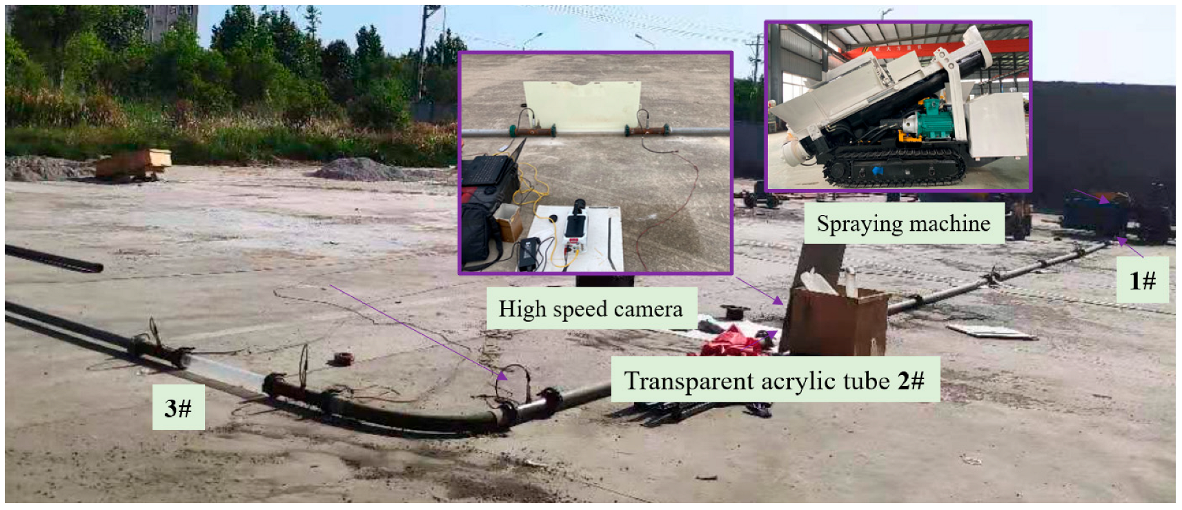
To investigate the flow regime evolution of stiff shotcrete material during pneumatic conveying, a customized experimental platform was established. The platform primarily consists of a JSLT7-L stiff shotcrete machine, an air compressor, a vector frequency converter, a vortex flowmeter, a high-speed camera, conveying pipelines, and transparent acrylic pipes (as shown in
Figure 1). The JSLT7-L stiff shotcrete machine, manufactured by Shandong Wetlab Mining Equipment Co., Ltd. (Jining City, China), adopts a hydraulic drive system with a rated production capacity of 7 m
3/h and a maximum horizontal conveying distance of 500 m. The air compressor used in the experiment is the XLD75A model (Shanghai Guanke Machinery Co., Ltd. Shanghai City, China), which provides a maximum airflow of 475 m
3/h and a maximum pressure of 0.8 MPa, ensuring a stable high-pressure airflow. The vortex flowmeter (Model: SGLUGD-DN50, Shanghai Shango Sensor Technology Co., Ltd. Shanghai City, China) is employed to precisely measure the airflow rate and incorporates a mathematical model for automatic pressure and temperature compensation.
The total length of the experimental pipeline is approximately 36 m, consisting of two horizontal straight sections of about 18 m each and a 90° elbow with a curvature radius of 4. The pipes designated for observation are made of transparent acrylic, with an internal surface roughness of approximately 0.2 μm, and has inner diameters of 51 mm, 63 mm, and 70 mm, allowing for the study of the effect of pipe diameter on flow regimes. Three transparent acrylic pipe segments (each 0.8 m in length) are positioned at different locations: Initial conveying section (1#), stable conveying section (2#) and post-elbow section (3#). These transparent sections facilitate direct observation of material flow characteristics at different pipeline positions. A high-speed camera (Phantom v611, average frame rate: 550 FPS, maximum resolution: 1280 × 800) is employed to capture particle motion trajectories and the evolution of flow regimes in real-time.
2.2. Material Properties
The stiff shotcrete material used in the experiment is composed of cement, fine aggregate, coarse aggregate, and tap water at a mass ratio of 1:2.25:1.5. The cement used is P·O 42.5 ordinary Portland cement, while the fine aggregate consists of river sand with a moisture content not exceeding 6%. The coarse aggregate includes washed crushed stone and pebble fragments with low clay content. Before mixing, the coarse aggregate is screened through a 10 mm × 10 mm mesh sieve to ensure that the maximum particle size does not exceed 10 mm. To investigate the effect of the water–cement ratio on particle adhesion and flow behavior, the experiment is designed with three levels of water–cement ratio: 0.1, 0.2, and 0.3, based on site construction characteristics.
2.3. Experimental Design
The experiment focuses on examining the influence of air velocity, water–cement ratio, and pipe diameter on the flow regime evolution of stiff shotcrete material. The parameters are set as follows: Air velocity: 279 m3/h, 328 m3/h, 377 m3/h, 426 m3/h, and 475 m3/h. Water–cement ratio: 0.1, 0.2, and 0.3. Pipe diameter: 51 mm, 63 mm, and 70 mm. Each experimental trial maintains a conveying duration of approximately 10 s to ensure the collection of sufficient particle motion data. During the experiment, the air compressor generates a stable high-pressure airflow, which is dried before passing through a 5-m pipeline connected to the vortex flowmeter. This setup ensures that the airflow reaches a stable state before entering the flowmeter.
To ensure the reliability of experimental observations, each test condition was repeated three times under identical parameters. The flow regime transitions and particle behaviors were found to be highly consistent across repeated runs. Representative visual data presented in this paper were selected from these repeated experiments.
While the primary focus of this study is on qualitative flow regime identification, we acknowledge the importance of statistical uncertainty in engineering applications. Due to the complexity of the multi-scale particle system and the visual nature of the measurements, a full quantitative uncertainty analysis (e.g., standard deviations, confidence intervals) was not performed. However, care was taken to maintain consistent experimental setup conditions (air pressure, pipe geometry, material preparation, etc.), and flow patterns were cross-verified to enhance the credibility of the findings.
3. Results and Discussion
3.1. Flow Regime Evolution in the Initial Conveying Section
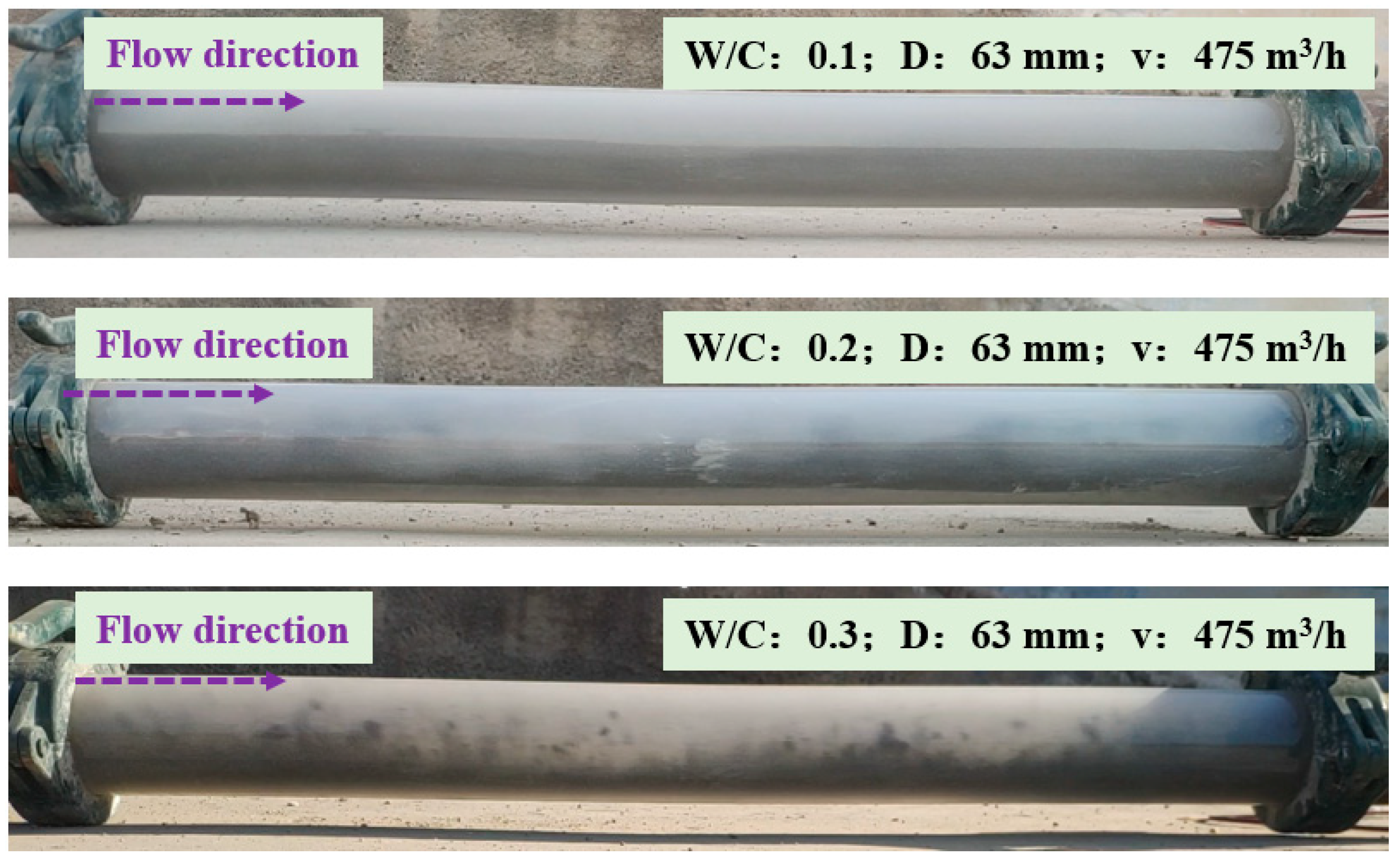
In the initial conveying section (approximately 1 m from the shotcrete machine outlet), the flow regime of stiff shotcrete material is primarily influenced by water–cement ratio and air velocity. Experimental results indicate that the water–cement ratio significantly affects particle distribution and flow behavior. At a water–cement ratio of 0.1, the low moisture content results in weaker liquid bridge forces between particles. Consequently, particles remain in a relatively uniform suspended state under the action of airflow (as shown in
Figure 2). In this case, flow characteristics are not pronounced, particle interactions are minimal, and the material exhibits good flowability. When the water–cement ratio increases to 0.2, the liquid bridge forces between particles strengthen, leading to partial particle agglomeration. The material primarily accumulates at the bottom of the pipeline, moving forward in a wavy pattern. At a water–cement ratio of 0.3, particle agglomeration becomes more pronounced, resulting in a clear bottom-layer flow. The thickness of the accumulated layer at the pipe bottom increases, while the number of suspended particles significantly decreases. These results demonstrate that an increase in the water–cement ratio enhances particle adhesion, promoting particle aggregation and reducing suspension behavior, resulting in a transition from suspended to bottom-layer flow.
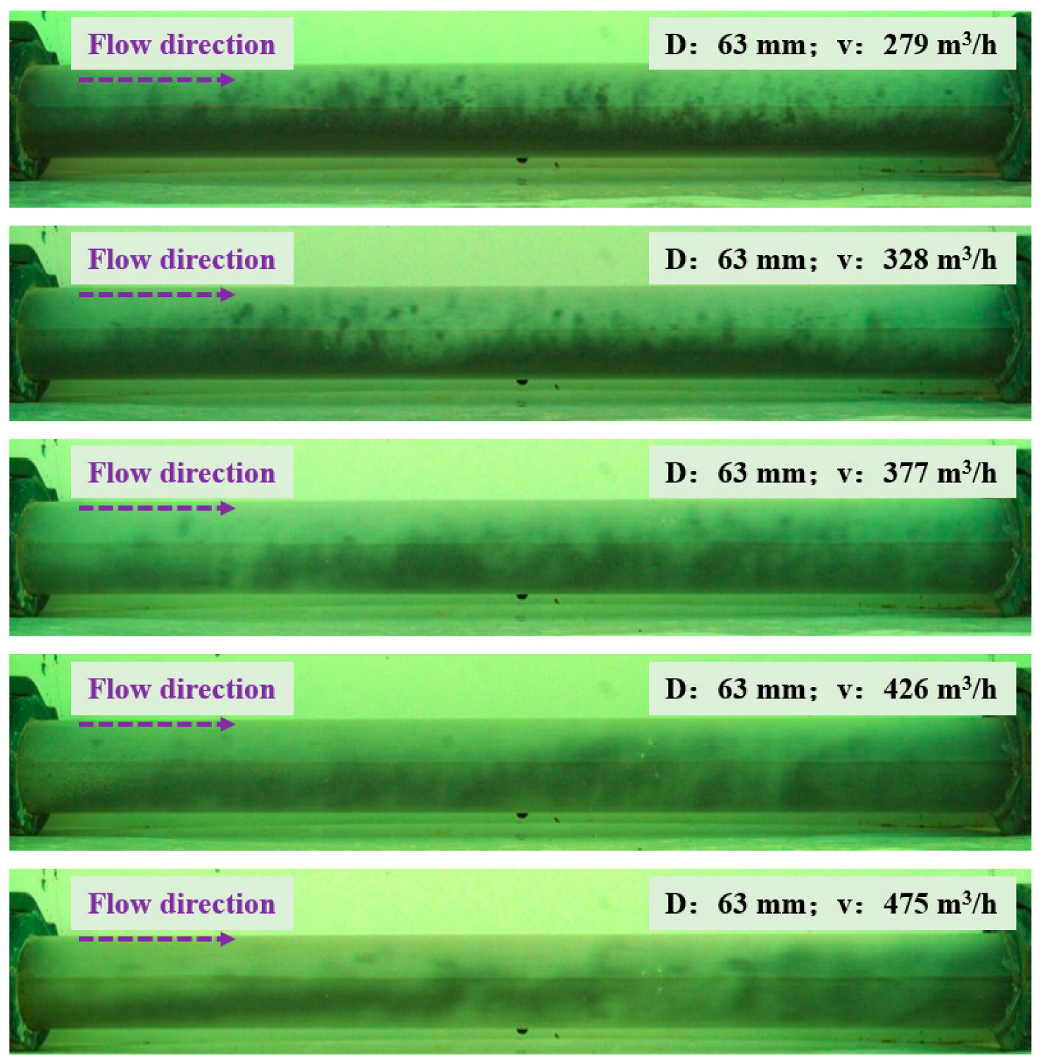
Air velocity also has a significant impact on the flow regime in the initial conveying section. At low air velocity (279 m
3/h), the material predominantly exhibits a dune flow pattern, where particles accumulate in a wave-like formation at the bottom of the pipeline (as shown in
Figure 3). As the air velocity increases to 328 m
3/h, some particles begin to suspend, but bottom-layer flow still remains dominant. At a high air velocity of 475 m
3/h, the suspension capacity of particles increases significantly, leading to a more uniform particle distribution within the pipeline, and a clear suspended flow regime is observed. Experimental results suggest that the flow regime evolution in the initial conveying section is primarily governed by the combined effects of inter-particle liquid bridge forces and aerodynamic drag. The synergistic effect of water–cement ratio and air velocity ultimately determines the dominant flow regime.
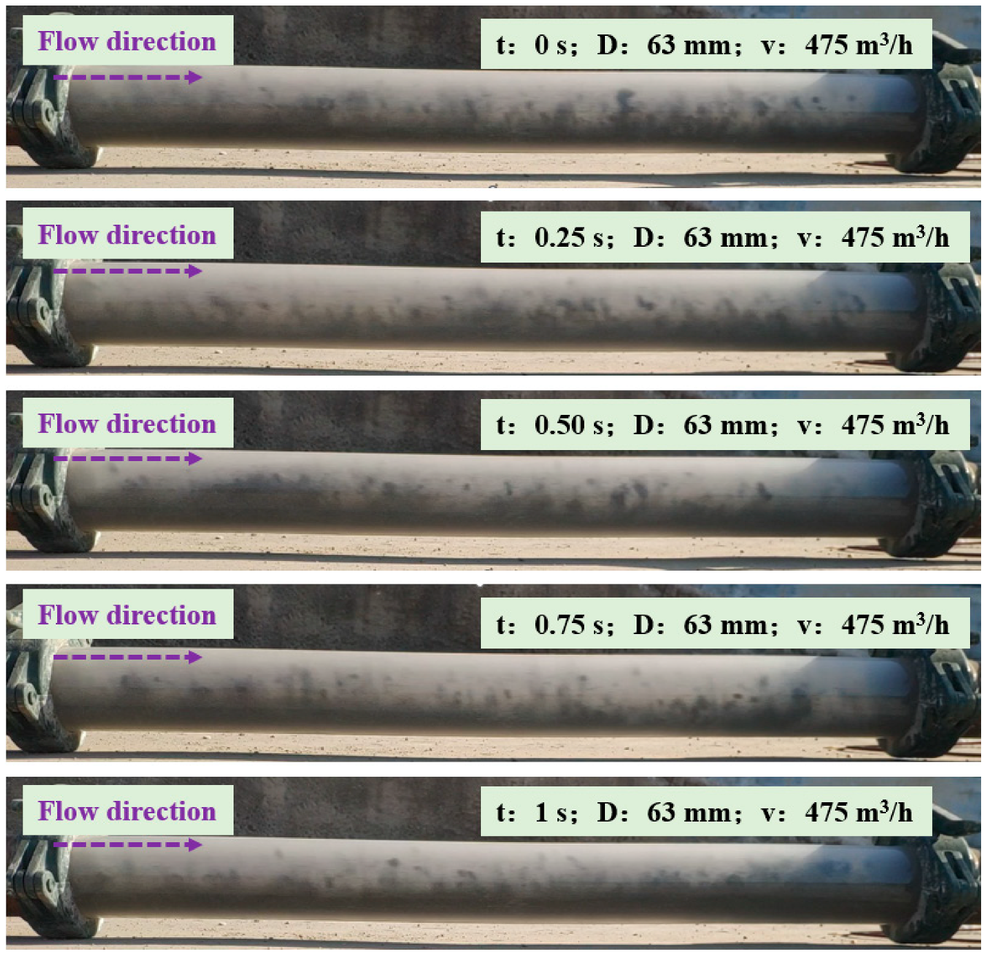
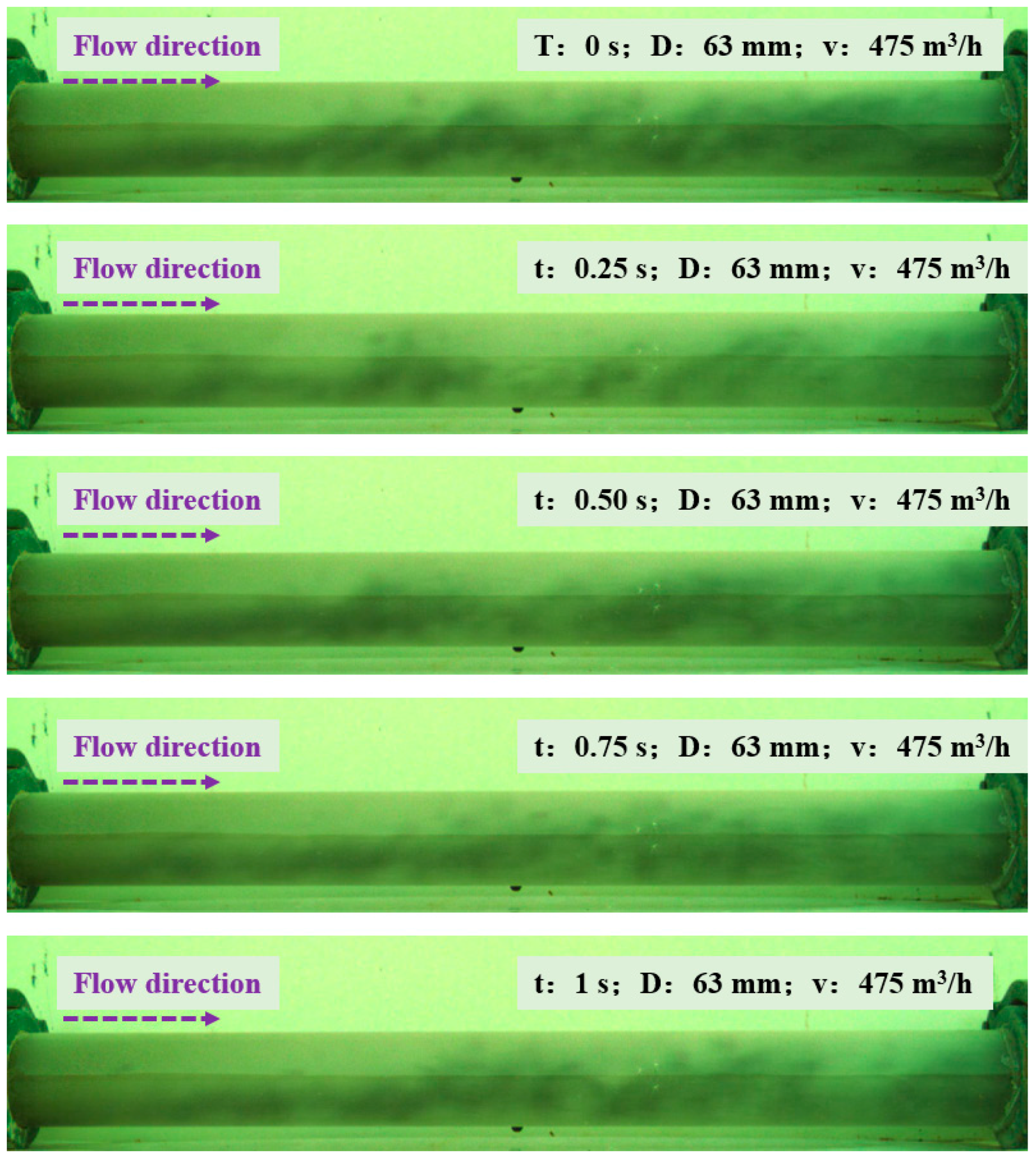
Figure 4 illustrates the instantaneous flow characteristics of stiff shotcrete material in the initial section of pneumatic conveying at different time intervals. The experiment was conducted under the same air velocity (475 m
3/h) and pipe diameter (63 mm) to observe the behavior of the material within the pipeline. The material distribution and motion were recorded at time intervals of 0 s, 0.25 s, 0.50 s, 0.75 s, and 1 s, aiming to reveal the transient flow characteristics and evolution trends of the material under airflow influence. From
Figure 4, it is evident that as the airflow begins to act, the material distribution is significantly affected, and particles start moving forward under airflow propulsion. During the 0–0.50 s interval, some particles begin to suspend in the airflow, creating a turbulent motion within the pipeline. In the gas–solid two-phase flow, solid particles gradually overcome static friction after being subjected to forces and begin to move under the combined influence of drag force and inertial force. Simultaneously, a portion of the particles starts accumulating at the bottom of the pipeline, forming an initial sedimentation flow pattern. During the 0.50–1 s interval, the flow characteristics stabilize, and a continuous particle accumulation layer remains at the pipeline bottom, propagating in a wave-like manner. At this stage, the particle flow state becomes more stable, with clearer flow regime characteristics, as both suspension and sedimentation behaviors reach a dynamic equilibrium. The interaction between particles, combined with aerodynamic drag and frictional forces, collectively governs the formation of a stable gas–solid two-phase flow regime in this section.
3.2. Flow Characteristics of the Stable Conveying Section
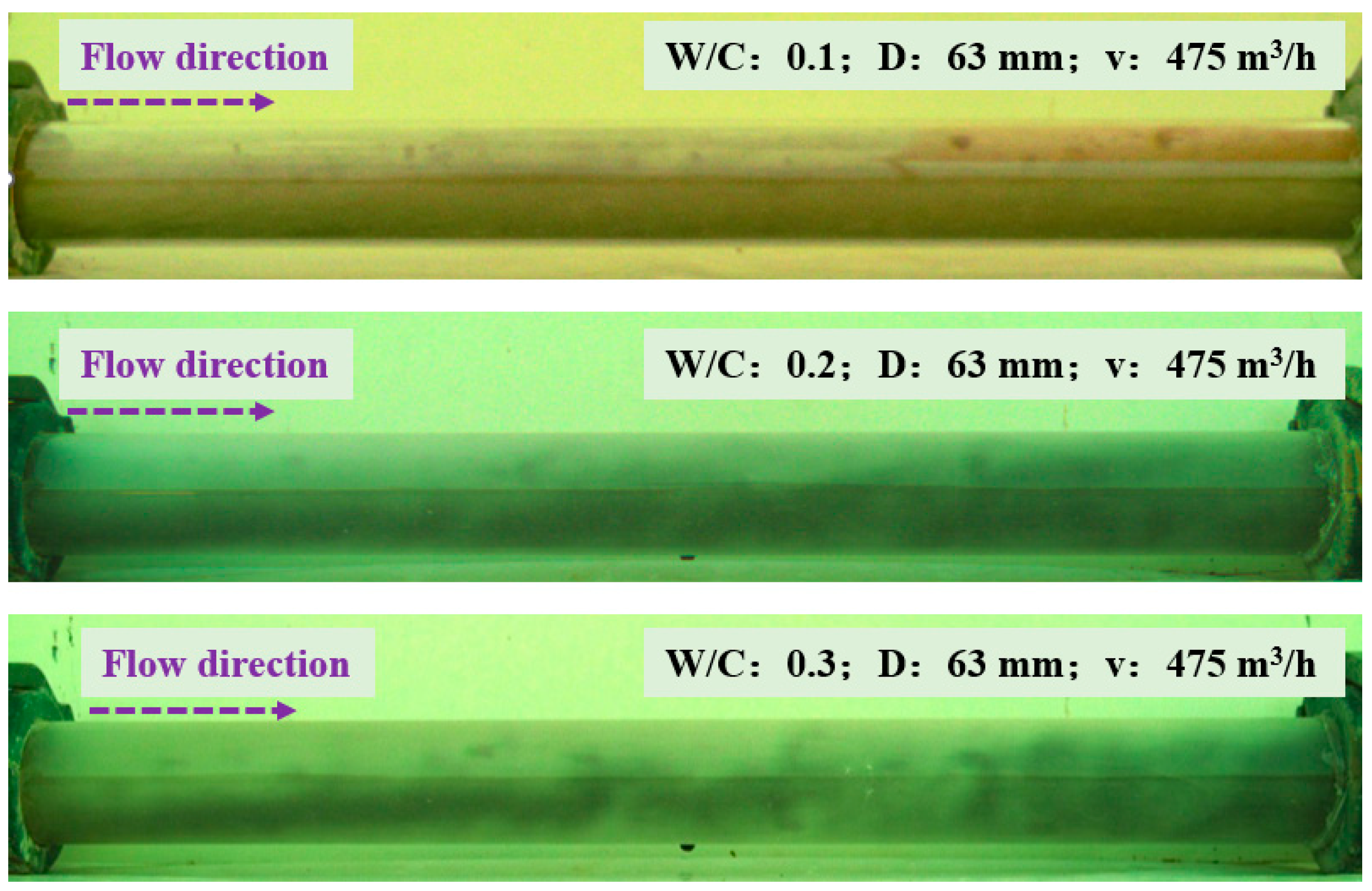
In the stable conveying section (approximately 15 m from the shotcrete machine outlet), the material flow state becomes more stable, and the flow regime characteristics become more pronounced. Experimental results indicate that the water–cement ratio plays a crucial role in determining the flow regime distribution in this section. At a water–cement ratio of 0.1, the inter-particle liquid bridge force is weak, resulting in a dilute-phase suspended flow pattern, where particles are uniformly distributed within the pipeline (as shown in
Figure 5). When the water–cement ratio increases to 0.2, the liquid bridge force between particles strengthens, leading to the formation of small particle agglomerates. The material distribution within the pipeline becomes more uniform, but the flow regime still predominantly exhibits dilute-phase suspended flow. At a water–cement ratio of 0.3, particle agglomeration becomes more pronounced, yet the material continues to exhibit a dilute-phase suspended flow pattern. Due to the increased adhesion between particles, the particle distribution remains uniform, and flow stability is significantly improved under the influence of the airflow. These findings suggest that in the stable conveying section, higher water–cement ratios enhance particle cohesion, promoting more uniform flow characteristics while maintaining stable dilute-phase suspended flow behavior.
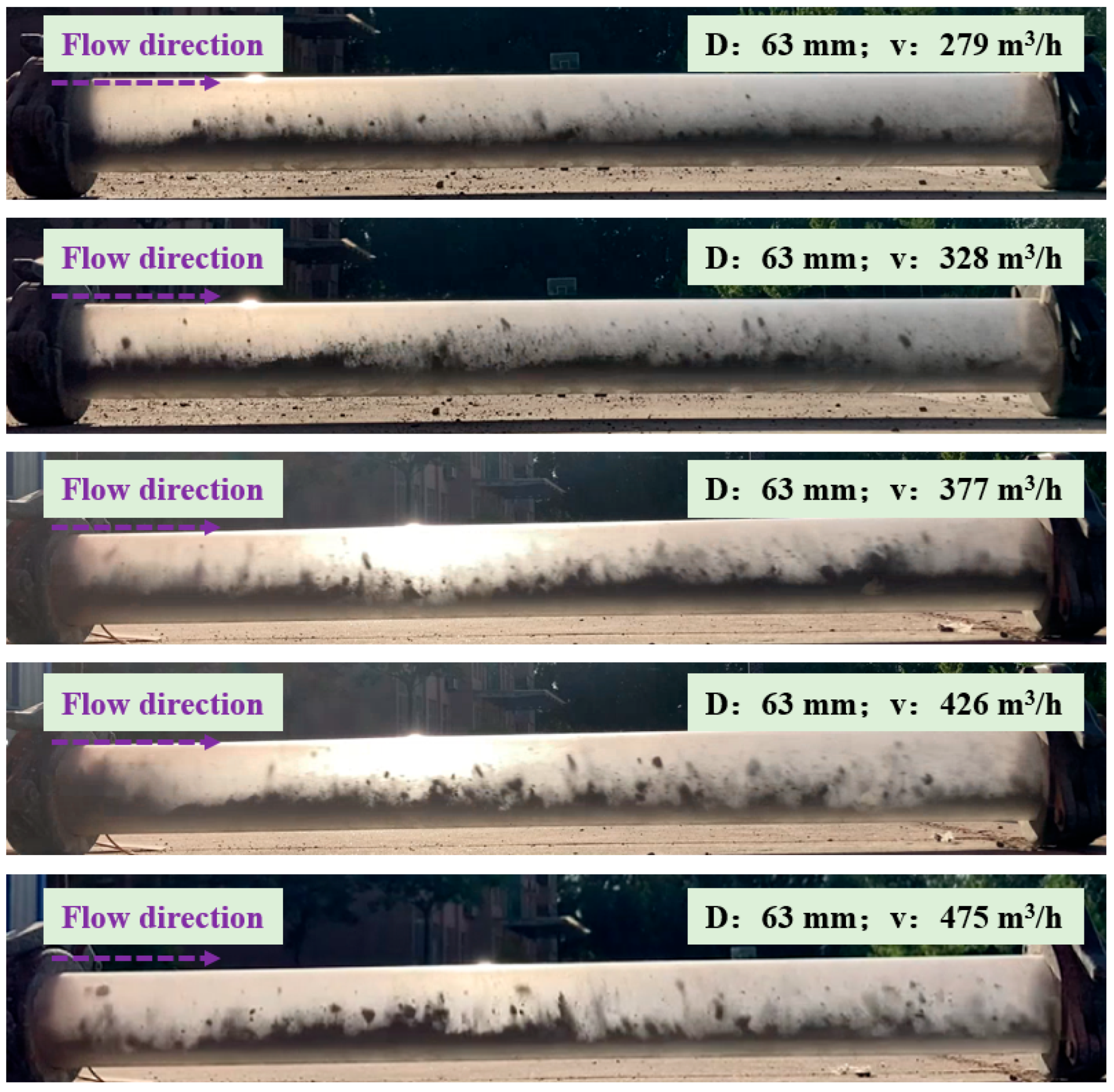
Air velocity has a significant influence on the flow regime in the stable conveying section. At a low air velocity of 279 m
3/h, the material predominantly exhibits a bottom-layer flow, where particles accumulate densely along the pipeline bottom, forming a thick deposition layer (as shown in
Figure 6). As the air velocity increases to 328 m
3/h, the flow state transitions to a dune flow regime, where wave-like accumulations of particles appear along the pipeline bottom. At an air velocity of 377 m
3/h, the flow regime further transitions to stratified flow, forming a clear layering structure within the pipeline, with fewer bottom-layer particles and an increased number of suspended particles. At the highest air velocity of 475 m
3/h, the flow regime completely shifts to suspended flow, where particles are evenly distributed within the pipeline, and flow characteristics improve significantly.
Figure 7 presents the instantaneous flow characteristics of stiff shotcrete material in the stable conveying section under an airflow rate of 475 m
3/h and a pipe diameter of 63 mm. The experiment records material distribution and motion states at time intervals of 0 s, 0.25 s, 0.50 s, 0.75 s, and 1 s to analyze the transient flow behavior and its variation under airflow influence. At 0 s, the material has just entered the pipeline, displaying an initial dispersed state with a relatively uniform distribution. At 0.25 s, material flow trajectories begin to appear, showing the effective propulsion of airflow. While the material remains in a suspended state, localized particle agglomeration is observed. At 0.50 s, the flow characteristics become more distinct, with highly stable suspended flow. The gap between particles gradually decreases, indicating that the interaction forces between particles and airflow reach a balance, leading to a more stable flow pattern. At 0.75 s, the material distribution remains stable, with a uniform particle arrangement, reflecting the efficient performance of the pneumatic conveying system during this period. The material continues moving forward in a suspended state, and although particle aggregation weakens slightly, it still persists. At 1 s, the flow characteristics fully stabilize, and the material is evenly distributed throughout the pipeline, signifying that the system has achieved a steady-state suspended flow regime. These results indicate that in the stable conveying section, a higher air velocity promotes uniform material distribution, ensuring a steady and efficient conveying process. The interaction between airflow drag, particle inertia, and inter-particle forces ultimately determines the long-term stability of the gas–solid two-phase flow.
3.3. Flow Regime Degradation in the Post-Elbow Section
In the post-elbow section, the change in airflow direction and the loss of momentum lead to significant alterations in material flow behavior. Experimental results indicate that the main effects of the elbow on the flow regime are increased particle deposition and reduced flow stability. In the initial stage after the elbow, the airflow velocity decreases sharply, causing particles to rapidly settle under gravity, forming a distinct bottom-layer flow pattern. As the conveying distance increases, the flow state gradually stabilizes, but the bottom-layer flow remains dominant, indicating a persistent decline in flow stability compared to the upstream sections. These findings suggest that the elbow-induced flow regime degradation is primarily due to momentum loss, reduced suspension capacity, and increased gravitational settling. This phenomenon highlights the need for optimizing pipeline design, particularly in long-distance pneumatic conveying systems, to minimize flow instability and particle deposition in the post-elbow region.
The water–cement ratio has a significant impact on the flow regime in the post-elbow section. At a water–cement ratio of 0.1, the liquid bridge force between particles is weak, leading to rapid particle deposition after the elbow. As a result, a pronounced bottom-layer flow is observed (as shown in
Figure 8). With an increase in the water–cement ratio to 0.2, inter-particle cohesion strengthens, enhancing material stability in the airflow and slowing down the deposition rate. At a water–cement ratio of 0.3, particle agglomeration becomes more prominent, and the flow state stabilizes after the elbow, resulting in a reduced bottom-layer flow characteristic. These findings indicate that a higher water–cement ratio improves material suspension stability, thereby reducing particle deposition and mitigating the flow regime degradation after the elbow.
The influence of air velocity on flow regime degradation in the post-elbow section is relatively minor compared to that of the water–cement ratio. At a low air velocity (279 m
3/h), material deposition after the elbow occurs rapidly, leading to a dominant bottom-layer flow (as shown in
Figure 9). As the air velocity increases to 475 m
3/h, the suspension capacity of particles improves, and the deposition rate decreases, but the bottom-layer flow remains evident. Experimental results suggest that flow regime degradation in the post-elbow section is primarily governed by the combined effects of particle inertia and gravity. While air velocity and water–cement ratio jointly influence the final flow regime, their effects are secondary to the fundamental forces driving particle deposition. These insights highlight the need for flow regime optimization strategies, such as modifying elbow geometries or adjusting operating parameters, to minimize material deposition and maintain stable pneumatic conveying performance.
3.4. Effect of Pipe Diameter on Flow Regime Distribution
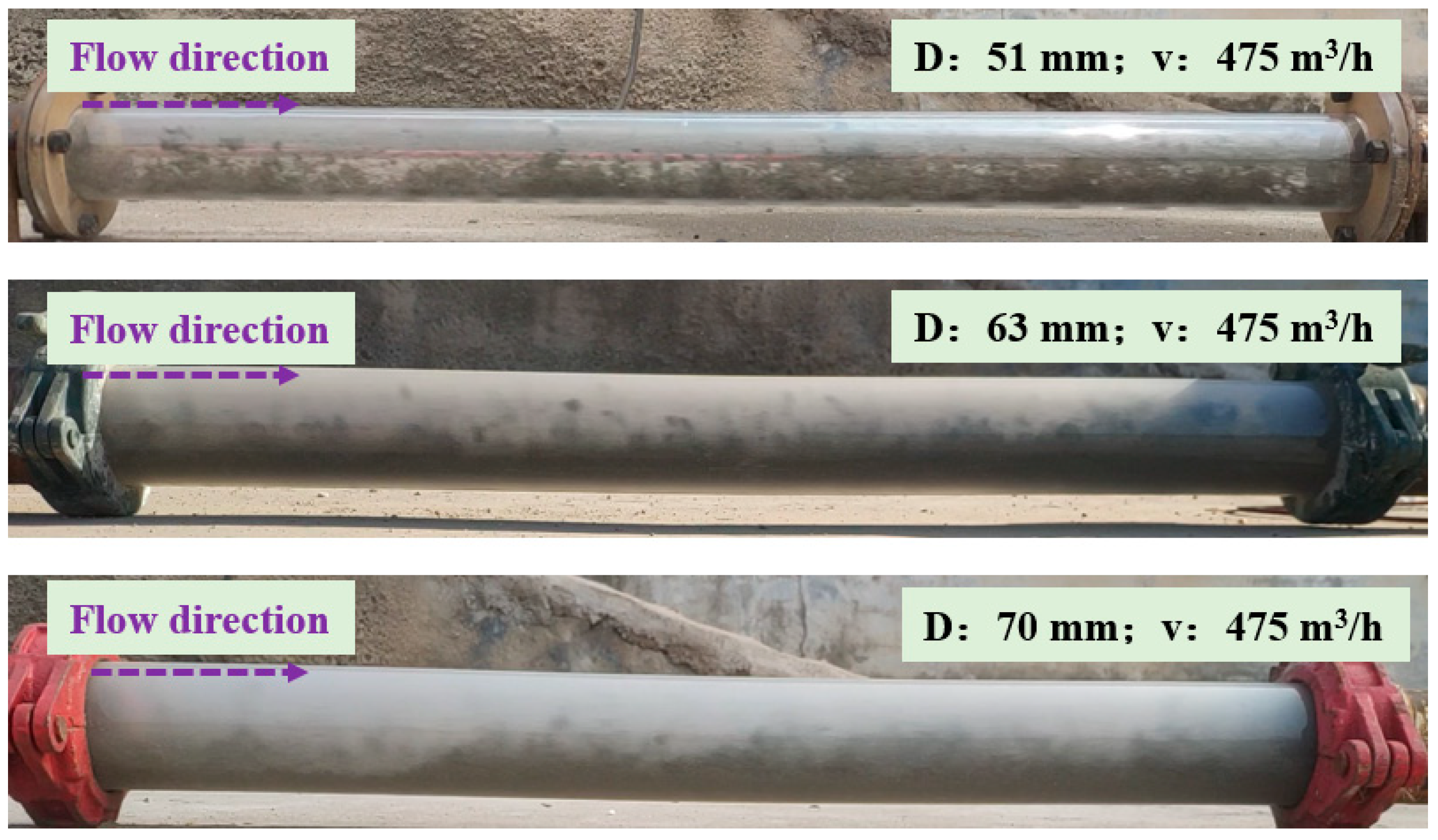
Pipe diameter has a significant impact on the flow regime distribution of stiff shotcrete material. Experimental results indicate that under the same air velocity (475 m
3/h), a smaller pipe diameter results in a higher airflow velocity, thereby enhancing the suspension capacity of particles. At a pipe diameter of 51 mm, the material predominantly exhibits a suspended flow regime, with particles evenly distributed within the pipeline under the influence of airflow (as shown in
Figure 10). As the pipe diameter increases to 63 mm, the airflow velocity slightly decreases, reducing the suspension capacity of particles. Consequently, bottom-layer flow characteristics begin to emerge. When the pipe diameter further increases to 70 mm, the airflow velocity significantly decreases, leading to a further reduction in particle suspension capacity, and the material primarily exhibits a bottom-layer flow regime. These findings suggest that smaller pipe diameters promote suspended flow, whereas larger pipe diameters favor bottom-layer flow, highlighting the critical role of pipe size in optimizing pneumatic conveying performance for stiff shotcrete material.
3.5. Mechanism Analysis of Flow Regime Evolution
The flow regime evolution of stiff shotcrete material in pneumatic conveying is primarily influenced by the combined effects of inter-particle forces and aerodynamic drag. In the initial conveying section, the balance between liquid bridge forces and aerodynamic drag determines the flow regime characteristics. As the conveying distance increases, inter-particle forces gradually weaken, and aerodynamic drag becomes the dominant factor, leading to a more stable flow regime. In the post-elbow section, due to the change in airflow direction and loss of momentum, particle inertia and gravity become the dominant factors, causing the flow regime to degrade from suspended flow to bottom-layer flow.
The water–cement ratio significantly influences flow regime evolution by affecting liquid bridge forces between particles: Under a low water–cement ratio, the liquid bridge forces are weak, and particles remain uniformly suspended in the airflow. Under a high water–cement ratio, the liquid bridge forces increase, leading to enhanced particle agglomeration, which in turn strengthens bottom-layer flow characteristics.
Air velocity plays a critical role in flow regime evolution by influencing aerodynamic drag: At low air velocity, aerodynamic drag is insufficient in overcoming gravity, resulting in a dominant bottom-layer flow regime. At high air velocity, aerodynamic drag is significantly enhanced, increasing particle suspension capacity, and leading to a transition toward a suspended flow regime.
Pipe diameter influences flow regime distribution by altering airflow velocity: In small-diameter pipes, the airflow velocity is higher, enhancing particle suspension capacity, resulting in a dominant suspended flow regime. In large-diameter pipes, the airflow velocity decreases, reducing particle suspension capacity, leading to a dominant bottom-layer flow regime.
