Article

Research on BIM Modeling of Steel Bridges Based on IFC Extensions

1
School of Emergency Science, Xihua University, Chengdu 610039, China
2
Kunming Atide Software Co., Ltd., Kunming 650106, China
*
Author to whom correspondence should be addressed.
These authors contributed equally to this work.
Buildings 2025, 15(18), 3376; https://doi.org/10.3390/buildings15183376
Submission received: 13 August 2025 / Revised: 5 September 2025 / Accepted: 15 September 2025 / Published: 17 September 2025
(This article belongs to the Special Issue Novel Steel and Steel-Concrete Composite Structures)

Abstract

To address the practical needs for data sharing and exchange in the bridge engineering domain, this study creatively fills the definitional gap of IFC entities for steel bridges. In response to the deficiencies arising from the absence of domain-layer entity information in the IFC standard architecture, an extension strategy is proposed that integrates new entity definitions with customized property sets to enrich and formalize the steel bridge domain. On this basis, a foundational data framework for steel bridge structures is established, encompassing extended definitions for spatial structural units, assemblies, components, and parts. The customized property sets further expand the entity attributes related to the design and fabrication stages, thereby developing an IFC-based manufacturing information model for steel bridges. Furthermore, a parametric BIM modeling approach for steel bridges is introduced on the 3DEXPERIENCE platform, employing IfcOpenShell to inject semantic information and export models in standard IFC format. The proposed IFC extension and modeling methodology is demonstrated through its application to the Chengdu Q7 North Pedestrian Bridge project, confirming its practical value in enhancing the completeness and transferability of steel bridge BIM model information from the design phase through to fabrication.

1. Introduction

With the widespread adoption of Building Information Modeling (BIM) technologies in the architecture and infrastructure sectors, their application in complex steel structures—particularly irregularly shaped steel bridges—has been steadily deepening, thereby driving the digitalization and intelligent transformation of the infrastructure industry [1]. By constructing comprehensive digital information models, BIM enables the integration of data across the design, construction, and operation stages, significantly enhancing project collaboration, improving management performance, and reducing resource consumption [2]. Its extensive use in engineering practice has accelerated the transition of project management from traditional implementation methods to model-centered collaborative workflows, thereby optimizing communication mechanisms and improving the efficiency of information exchange [3].
Steel bridge projects, however, typically involve complex multidisciplinary collaboration, where the requirements for BIM data vary substantially among stakeholders. For instance, design teams primarily focus on geometric information, whereas manufacturing and construction phases place greater emphasis on fabrication-related attributes [4]. This collaborative environment highlights the pressing need for effective data exchange and interoperability among heterogeneous BIM tools employed by different project participants [5]. Yet, mainstream BIM software frequently exports integrated models as monolithic deliverable files, which exacerbates information redundancy and increases data complexity, making issues of data sharing and exchange particularly prominent [6]. Furthermore, the heterogeneity of model formats generated by different BIM tools severely undermines data interoperability, leading to the emergence of “data silos” that constrain the in-depth application of BIM in the infrastructure sector [7]. To address these challenges, buildingSMART has actively promoted the extension of the Industry Foundation Classes (IFC) standard—both in terms of semantic scope and structural hierarchy—to meet the growing requirements for data exchange in the architecture and infrastructure industries [8]. As the most widely adopted open standard for BIM data, IFC provides a neutral and open format that facilitates seamless information exchange across heterogeneous BIM platforms [9]. By defining a unified model structure comprising objects, properties, and their interrelationships, IFC not only promotes cross-platform interoperability but also supports the representation of key business processes across design, construction, and operation stages, thereby covering the information requirements of the entire project lifecycle [10,11]. With the continuous evolution of industry applications, the IFC standard is also undergoing ongoing development to accommodate emerging modeling paradigms and digital workflow demands.
Nevertheless, while IFC has laid the foundation for cross-platform interoperability, its current architecture remains insufficient in addressing the high-precision information and semantic completeness required in the design and fabrication phases of steel bridges, thereby limiting the efficiency of data exchange and the accuracy of information transfer. In response, both domestic and international scholars have proposed a variety of IFC extension strategies to address domain-specific requirements and adapt to the development of emerging digital technologies [12]. Such extensions often involve the introduction of new physical components or conceptual entities, which are then integrated into the existing data model structure to enhance its semantic expressiveness [13]. This mechanism effectively supplements domain-specific information and exchange requirements originally absent from the IFC schema, thereby improving its applicability and robustness in complex architectural and infrastructural scenarios [14].
However, a systematic review of existing research (see Section 2) reveals that most IFC extension studies have primarily focused on meeting the information requirements of the design and construction stages—such as geometric representation, structural analysis, and construction management—while offering only limited support for the detailed process and production management data required during the manufacturing stage. Many of these efforts emphasize the definition of macroscopic component types or the addition of analytical attributes, yet they fall short of addressing the part-level semantic descriptions and assembly logic essential to manufacturing processes. Moreover, current extension practices are often problem-specific and fragmented, resulting in poor compatibility and reusability across different extension models. The absence of a unified, systematic top-level framework has hindered the development of comprehensive information modeling for steel bridges. Consequently, discontinuities frequently occur in the transmission of design information along the manufacturing chain, making it difficult to adequately support the demands of high-precision fabrication and digital delivery of steel bridges.
In response to these limitations, the present study aims to fill this gap by addressing the central research question: How can a systematic IFC extension framework be developed to enable seamless information transfer across the full lifecycle of steel bridges, from design through to manufacturing?
(1)
Proposes an IFC-based information modeling framework for the full lifecycle of steel bridges. By integrating static entity extensions with dynamic property set customization, a structured data system encompassing four hierarchical levels—spatial units, assemblies, components, and parts—is established. Corresponding property sets are also defined for both design and manufacturing stages, thereby addressing the current gap in component classification systems and semantic attribute representation.
(2)
Implements the extended model on the 3DEXPERIENCE platform. A parameterized BIM modeling workflow for steel bridges is developed, underpinned by the IFC extension. The enriched models are exported in IFC standard format using the IfcOpenShell toolkit, enabling cross-platform and cross-stage data exchange.
(3)
Validates the proposed framework through a real-world case study of the Chengdu Q7 North Pedestrian Bridge. The evaluation considers multiple dimensions, including semantic completeness, cross-platform readability, and engineering applicability. The results confirm the practical value of the proposed IFC extension and modeling methodology in enhancing the information integrity of steel bridge BIM models and improving the reliability of design-to-manufacturing information transfer.

2. Literature Review

2.1. Methods for Extending the IFC Model

The Industry Foundation Classes (IFC) standard was initially developed by the International Alliance for Interoperability (IAI), based on the STEP standard and modeled using the object-oriented EXPRESS language. It is characterized by openness, a structured data architecture, and extensibility [15]. The hierarchical modeling framework of IFC provides both readability and scalability, and has been widely applied in data modeling and information exchange across the architecture and infrastructure sectors [16]. At present, the IFC standard is maintained by buildingSMART and continues to expand into infrastructure domains such as roads, railways, bridges, and tunnels. Building upon the IFC4.3 standard, this study focuses on the definition of entities and the extension of property sets for semantic modeling of bridge components, with the aim of enhancing the adaptability and semantic expressiveness of IFC in infrastructure engineering.
As illustrated in Figure 1, the IFC extension framework proposed in this study comprises two complementary mechanisms: static extension and dynamic extension. The choice between entity extension (static) and property set extension (dynamic) follows a semantics-driven decision process, guided by the principle that a new entity should be created only when the unique semantics cannot be sufficiently represented through property sets.
  • Static extension involves introducing new domain-specific entities to augment the original IFC schema, thereby accommodating modeling requirements for structural elements initially absent from the standard (e.g., components in bridges and railways). These newly defined entities are organized through object-oriented inheritance and ultimately exported as EXPRESS schema files, ensuring seamless recognition and parsing by compliant software platforms. The IFC data schema supports multiple representation formats, including HTML, EXPRESS, XSD/XML, and OWL. In bridge engineering, model development is primarily implemented using EXPRESS or XML representations [17].
  • Dynamic extension refers to enhancing the existing IFC schema by adding user-defined Property Sets (Psets), which supplement domain-specific information without altering the original schema [18]. This approach provides high compatibility and flexibility, making it particularly suitable for strengthening and refining information requirements in the design and fabrication stages of steel bridges.
In summary, entity extensions define “what it is”, whereas property set extensions describe “what properties it has.” The combination of both ensures semantic richness while preserving maximum compatibility with the existing standard.

2.2. Applications and Limitations of IFC in Bridge Engineering

With the deepening application of the IFC standard in infrastructure domains such as bridges and railways, the limitations of its original data structures and semantic framework in supporting domain-specific and fine-grained component modeling have become increasingly evident. In response, scholars worldwide have proposed a variety of targeted IFC extension strategies to enhance the standard’s adaptability to specialized requirements. For instance, Lee and Jeong [19] developed an integrated steel bridge modeling framework based on STEP AP203 and AP209; however, the framework lacked explicit semantic definitions of spatial relationships among bridge components, thereby limiting the computer’s ability to infer such relationships. Lee [20] proposed a semantic modeling method for steel box-girder bridges using IFC property sets, where semantic identification items were clarified and component classification management was achieved. Yet, the multilayered semantic representations required by complex bridge structures extend well beyond the original expressiveness of IFC, which was primarily designed for the building domain.
To strengthen IFC models in structural analysis, spatial representation, and parametric control, many studies have introduced extensive entity and property set extensions. Park et al. [21] incorporated a mesh-free analysis method to extend IFC entities for supporting structural simulation of bridge systems. Ji et al. [22] enhanced the IFC-Bridge extension by introducing parameterized entities capable of representing dimensional constraints. Lee and Kim [23] proposed an IFC extension model integrating road and substructure elements for bridges, facilitating spatial layout management. Wu et al. [24] explored methods for integrating information models in geotechnical engineering and presented an IFC-based implementation pathway.
Entity extension has thus emerged as a critical strategy for enhancing the semantic expressiveness of IFC in response to domain-specific requirements. Zhu et al. [25] extended IFC entities and properties for prefabricated structures and proposed a top-down modeling method for prefabricated components. He et al. [26] combined entity extensions with customized property sets to enrich the semantic capacity of IFC for railway engineering. Yang and Li [27] improved modeling adaptability and semantic integrity of IFC-based models to meet the data exchange requirements of rack railway systems. Zhang et al. [28] applied IFC extension techniques to roller-compacted concrete dam modeling, validating their feasibility through a prototype system in hydraulic engineering. Wang et al. [29] extended the IfcSensor entity to support tunnel monitoring information, thereby advancing the informatization of infrastructure monitoring and management.
In addition to semantic limitations, insufficient efficiency of information exchange remains a critical bottleneck for the wider adoption of IFC. Zhang et al. [30] developed a high-performance IFC-based structural data exchange system and demonstrated its effectiveness. Lai et al. [31] proposed a data dictionary–driven interaction method that effectively addressed issues of data loss and false reporting during IFC-based exchanges. Bao et al. [32] established an IFC-based framework for bridge defect information modeling, enabling multi-platform visualization and integration. Sheik et al. [33] integrated construction schedule information into BIM models and developed an automated monitoring framework. Seo and Kim [34] embedded design codes into BIM models via IFC property sets, thereby fostering deeper alignment between modeling practices and regulatory standards. Zhiliang et al. [35] extended IFC property sets to construct a data structure supporting cost estimation, significantly improving the accuracy and efficiency of project management. Liu and Li [36] advanced the integration of BIM and BVBS through a systematic framework that combined IDM/MVD methodology, IFC schema extensions, and automated algorithms. Their approach substantially improved automation in rebar prefabrication while offering a generalized, open, and extensible solution that could also be applied to other prefabricated components, thereby promoting the digital and industrial transformation of the construction sector. Collectively, these studies provide vital modeling support for the digital representation of design codes and the integration of workflows in bridge engineering.
In summary, existing IFC extension studies have predominantly focused on three key areas: the definition of component types, support for structural analysis, and parametric modeling, employing approaches such as entity addition, parameter enhancement, and property set customization. Nevertheless, several critical limitations remain. The vast majority of research has concentrated on the information requirements of the design and construction phases—such as geometric representation, structural analysis, and construction management—while offering only limited support for the manufacturing stage. Although a few studies have explored the automation of prefabricated components, systematic approaches to incorporating manufacturing-related information are largely absent. Essential data for steel bridge fabrication, including welding procedure specifications, numerical control (NC) machining codes, part batch management, and quality inspection records, have yet to be comprehensively integrated into IFC extension frameworks, resulting in discontinuities in the transfer of design information along the production chain.
Many studies emphasize the definition of macroscopic component types or the augmentation of analytical attributes, but they fail to extend downward to the part-level semantics and assembly logic that are indispensable for manufacturing. Current extension practices are often developed in response to specific, isolated problems—such as supporting a particular analysis type or meeting a narrowly defined delivery requirement—leading to fragmented outcomes. Consequently, different extension models exhibit limited compatibility and reusability, and the absence of a widely accepted, systematic top-level framework hinders the development of unified information modeling for steel bridges. This fragmented landscape further exacerbates the risk of semantic inconsistency, obstructing large-scale collaboration across projects and platforms.
Unlike the building sector, which primarily emphasizes process modeling, the infrastructure sector requires dual semantic representation of both products and processes, encompassing operation and maintenance management, structural health monitoring, and construction workflows. While some studies have introduced ontology-based frameworks to enhance semantic reasoning and cross-platform compatibility, current IFC extension practices still face critical challenges, including methodological fragmentation, insufficient semantic consistency, and the lack of standardized development tools. Therefore, the development of a unified, semantically rich IFC extension model tailored specifically for bridge engineering has become an urgent necessity to advance the deeper application of BIM technologies in infrastructure projects.

3. Extension and Analysis of the IFC Standard Data Architecture

3.1. The Data Architecture of the IFC Standard

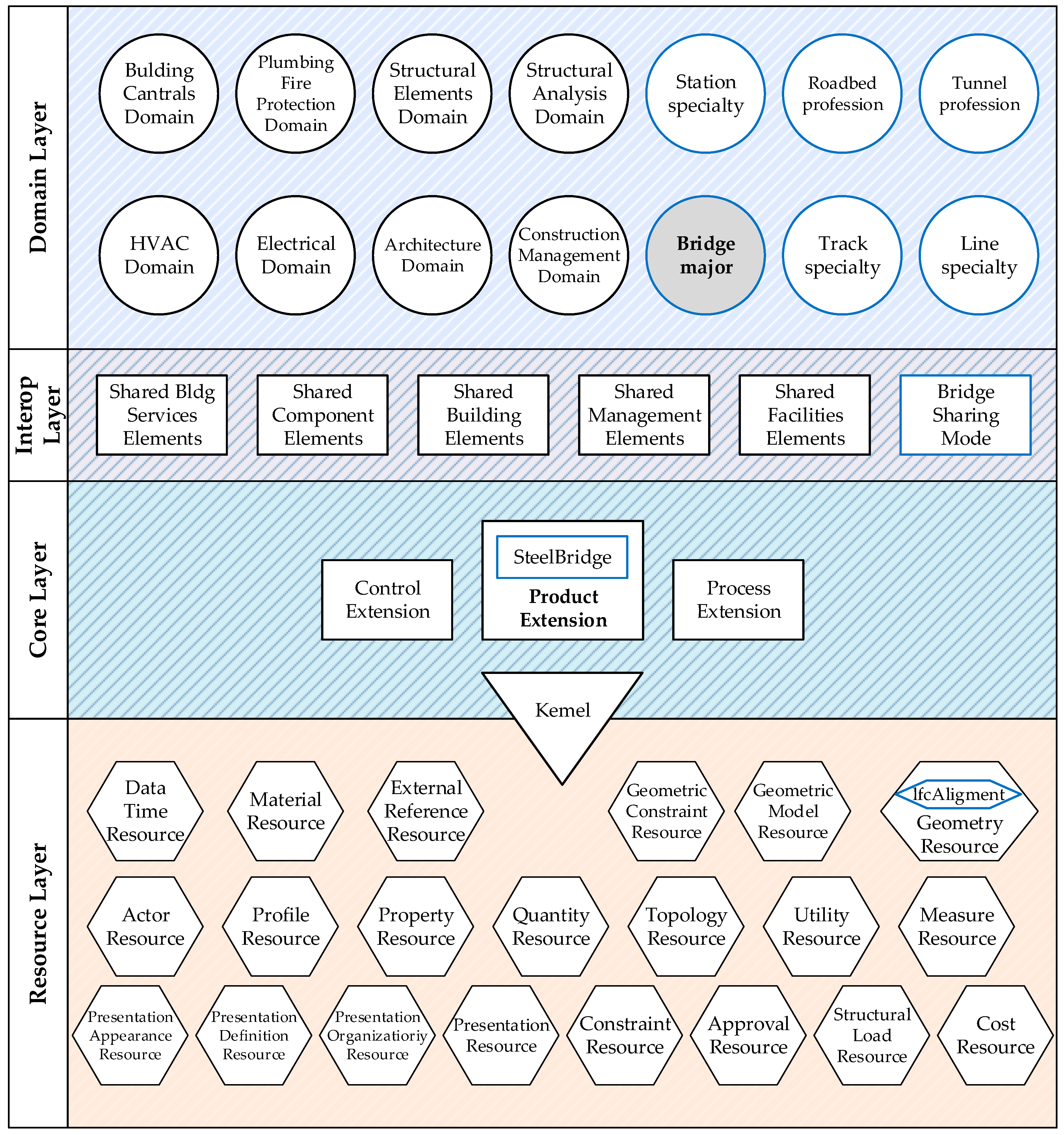
The architecture of the IFC standard is composed of four core hierarchical layers: the Resource Layer, Core Layer, Interoperability Layer, and Domain Layer. This architecture is grounded in object-oriented modeling principles and organizes information resources through mechanisms of inheritance and reference. It is designed to support modeling requirements across various disciplines and stages of the project lifecycle. A key structural constraint within this architecture is the “Gravity Principle,” which dictates that each layer may only reference components from its own level or from lower layers, prohibiting upward dependencies. This principle prevents cascading changes in lower modules caused by upper-layer modifications, thereby enhancing the overall stability, maintainability, and extensibility of the IFC schema.
This study builds upon the IFC4 standard and proposes a targeted extension of both entity structures and property sets to meet the modeling requirements of steel bridge structures. As illustrated in Figure 2, the extensions are implemented across the four hierarchical layers of the IFC architecture:
  • Core Layer: Introduction of core semantic concepts related to steel bridges, such as STEELBRIDGE.
  • Interoperability Layer: Addition of general-purpose entities for steel bridge modeling, including IfcBridgeElement.
  • Domain Layer: Definition of multiple domain-specific entities and property sets tailored to the steel bridge engineering context, with a focus on enhancing the expression of fabrication-related attributes.
  • Resource Layer: Extension of material resources and geometric representations, including the reuse of IfcAlignment to describe alignment and spatial positioning of steel bridge components.
Elements not subject to customization retain their original IFC definitions. Inheritance and reuse mechanisms are employed to ensure consistency and continuity across the extended schema, thereby enabling structured representation of heterogeneous and multi-source information in steel bridge projects.
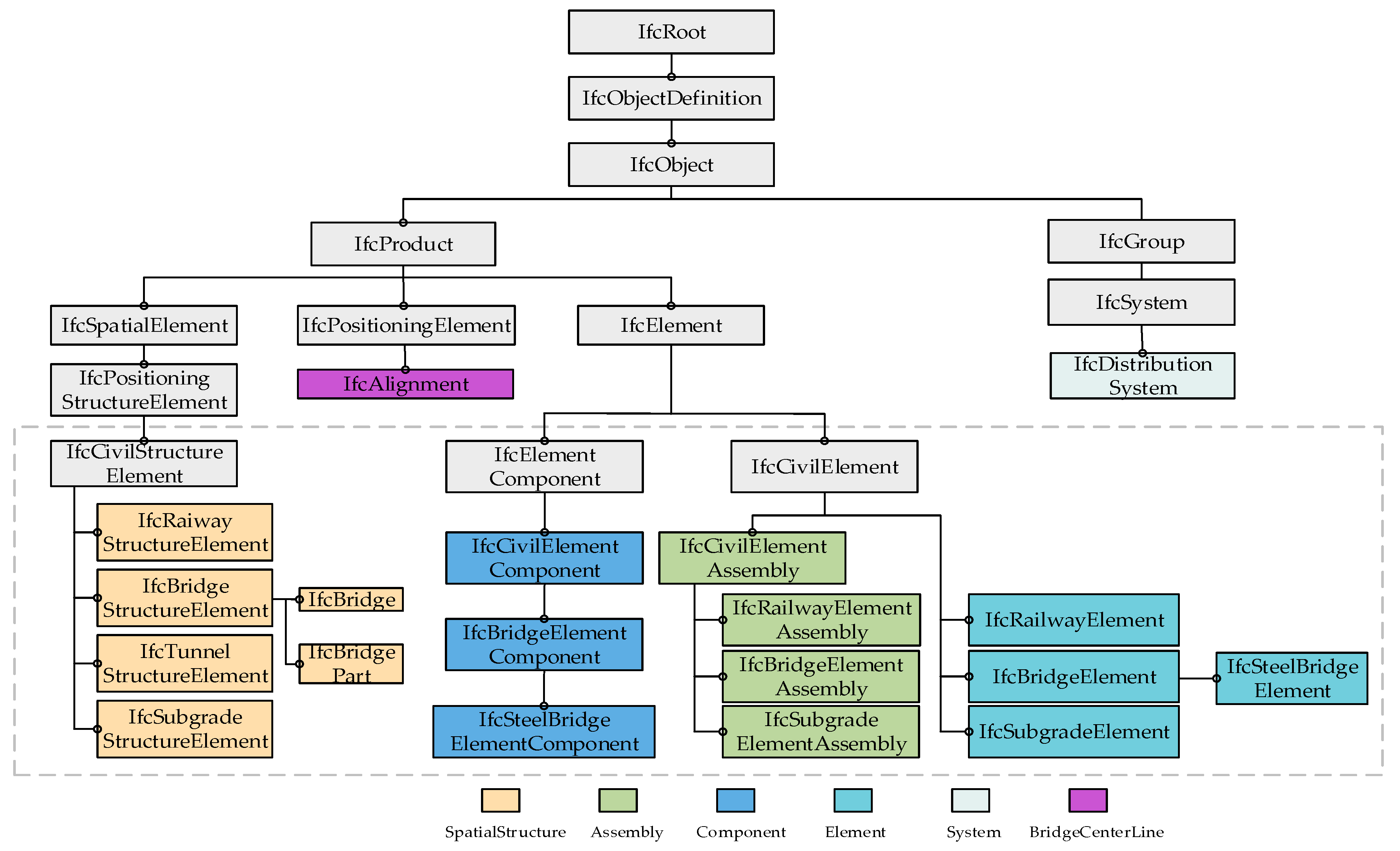
As illustrated in Figure 3, this study adopts a four-tier hierarchical extension strategy for entity inheritance, encompassing Spatial Structure Units, Components, Assemblies, and Parts:
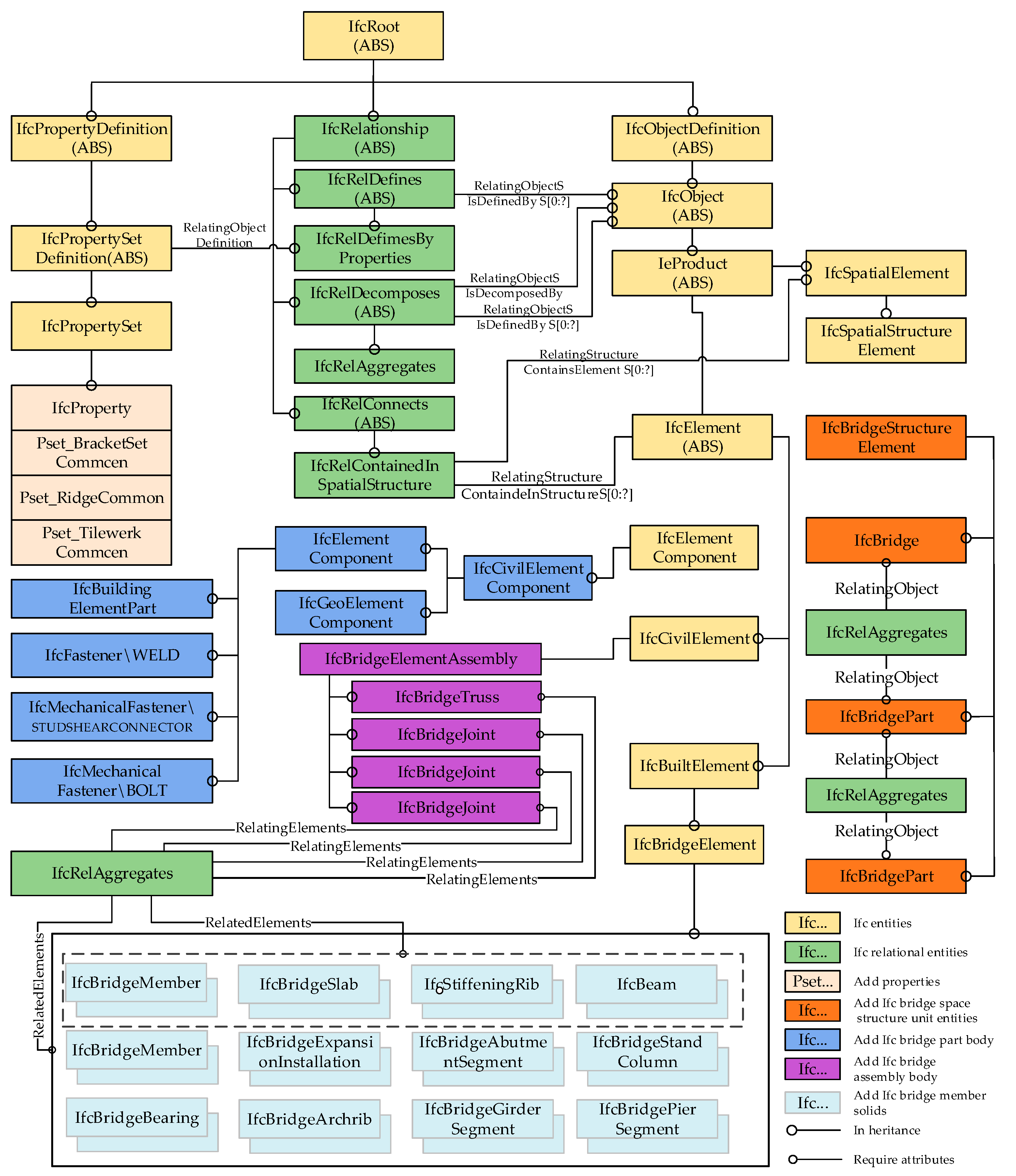
Spatial Structure Unit Level: From IfcCivilStructureElement, a specialized bridge spatial entity, IfcBridgeStructureElement, is derived. This is further refined into subclasses IfcBridge and IfcBridgePart, thereby accommodating varying scales and functional divisions of bridge structures. Together, IfcBridge and IfcBridgePart provide a semantic framework for describing the spatial decomposition of bridge projects.
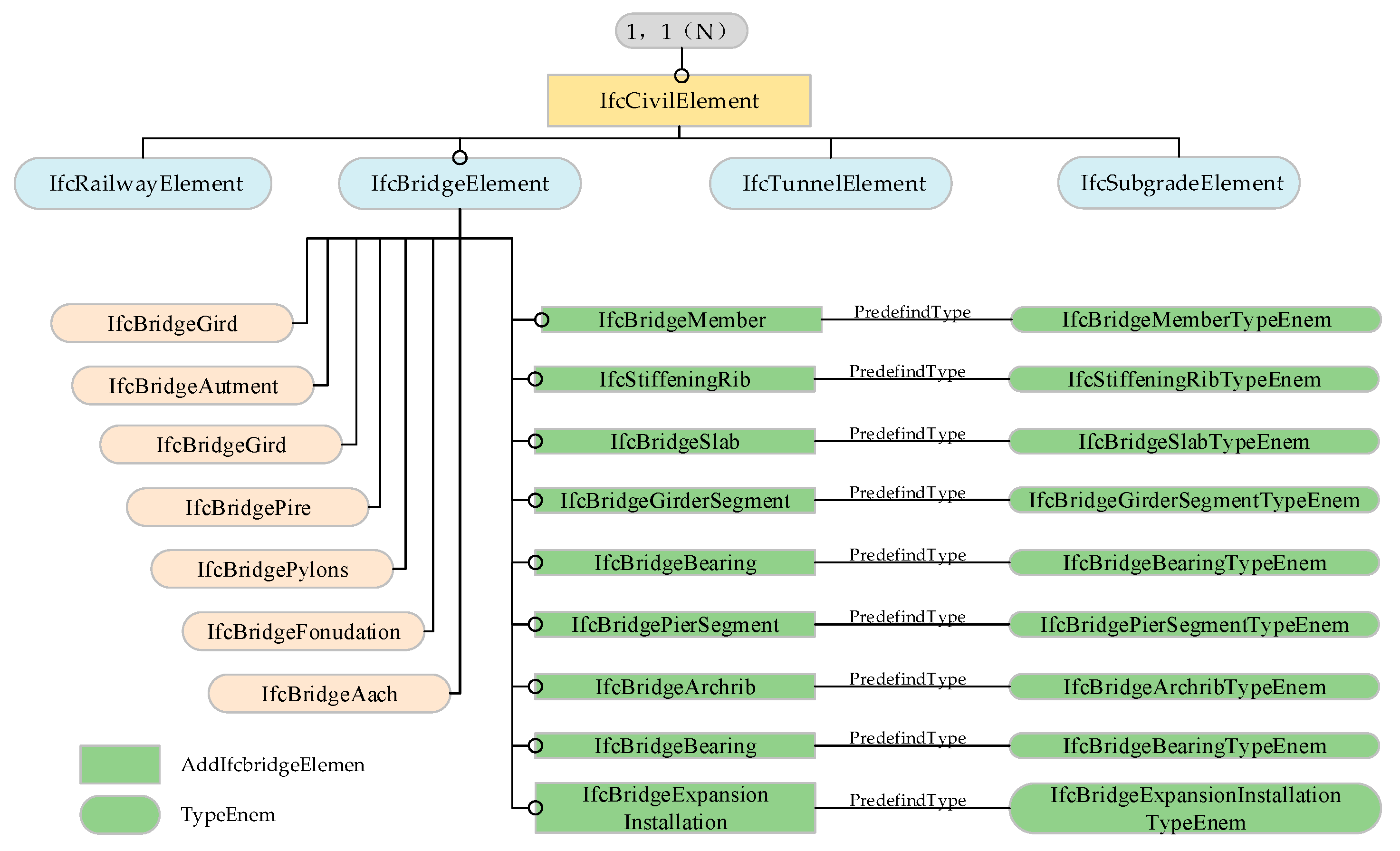
Component Level: From IfcCivilElement, the independent basic structural entity IfcBridgeElement (e.g., IfcSteelBoxGirder) is derived. To reflect the specificities of steel bridges, multiple domain-specific subclasses are defined, enabling precise semantic representation of diverse component types.
Assembly Level: From IfcCivilElementAssembly, the composite functional entity IfcBridgeElementAssembly (e.g., IfcBridgeTruss) is derived, representing structural assemblies composed of multiple components. Further refinements yield specialized assembly classes tailored to steel bridge applications.
Part Level: At the most granular scale, IfcElementComponent (e.g., IfcMechanicalFastener) is employed to represent subordinate elements such as connectors or stiffeners. A generalized bridge part class is defined to enhance interoperability and reusability across multiple disciplinary contexts.
This extension framework establishes a coherent semantic chain across spatial units, assemblies, components, and parts, thereby addressing the intricate structural relationships and topological modeling requirements inherent in steel bridge engineering.

3.2. Mechanisms for Extending the IFC Schema

With the widespread adoption of the IFC standard across global engineering domains, its entity types and semantic expressiveness have been significantly enriched. However, in practical modeling scenarios—particularly within complex infrastructure sectors such as bridge engineering—the predefined IFC entities and property sets are often insufficient to fully accommodate domain-specific information requirements. Consequently, the targeted extension of the IFC data model has become an inevitable trend. According to the official guidelines issued by buildingSMART, the IFC standard supports three primary mechanisms for extension:
(1)
Extension Based on Newly Defined Entities
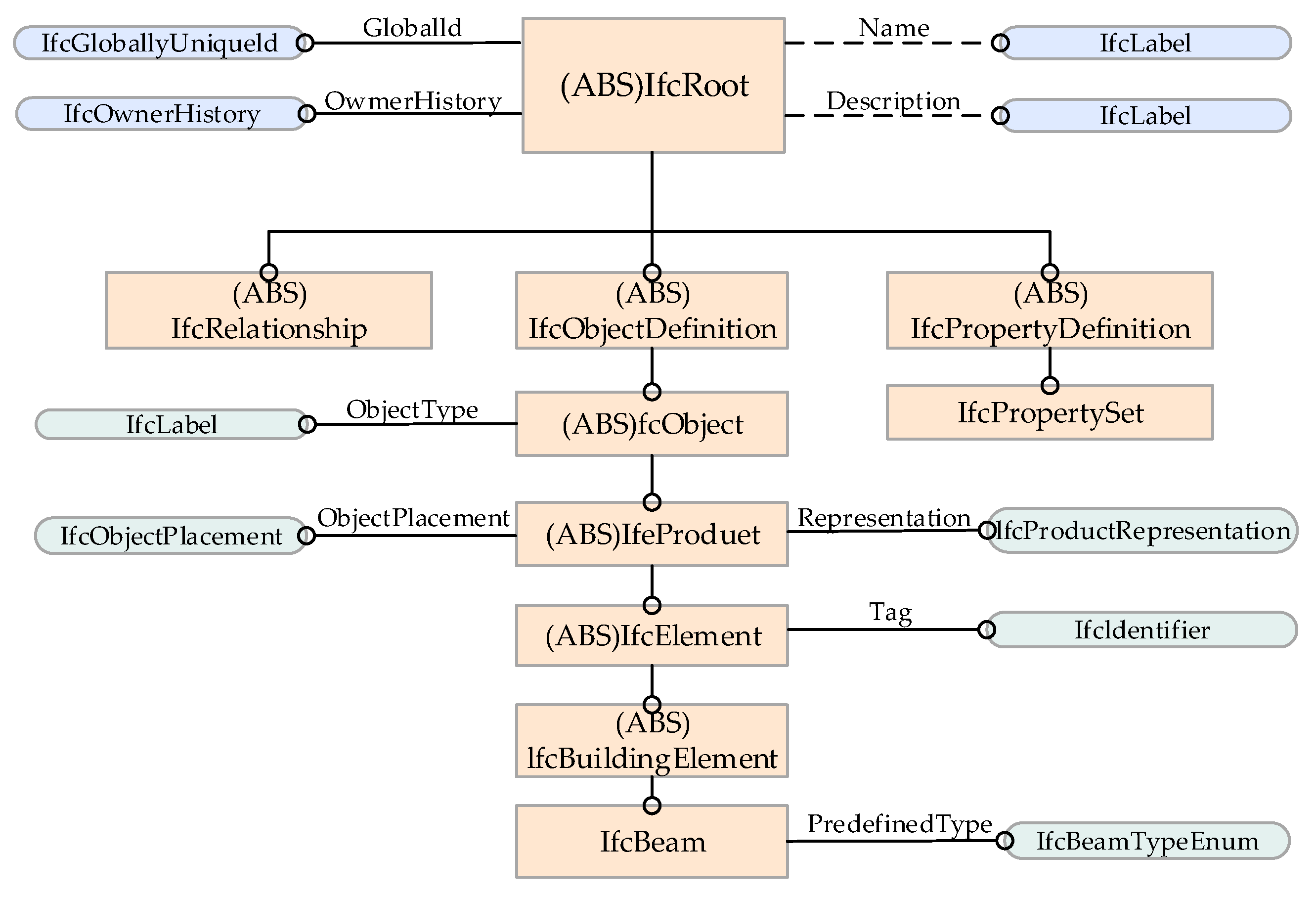
This extension strategy introduces domain-specific entities by establishing inheritance and associative relationships on top of the existing IFC architecture, primarily targeting the Extension Layer and Domain Layer. As illustrated in Figure 4, newly defined entities (e.g., IfcSteelBoxGirder) inherit general attributes—such as Name, GlobalId, OwnerHistory, and Description—through object-oriented derivation mechanisms. As a result, only specialized attributes need to be added, thereby avoiding semantic redundancy and enhancing the clarity and parsing efficiency of data representation. This approach is particularly well-suited for the standardized modeling of steel bridge BIM components.
(2)
Extension via Property Set Definitions
This approach enhances semantic representation by extending the IfcPropertySet entity with customized attribute sets tailored to specific modeling requirements. It offers high implementation efficiency and strong compatibility, making it an effective complement to entity-based extensions. In practical applications, existing standard IFC entity types should be prioritized, while customized property sets are introduced to achieve lightweight semantic augmentation. New entity definitions should only be adopted when existing entities fail to meet domain-specific semantic requirements.
(3)
Extension via IfcProxy Entities
This method is typically employed to represent non-standard objects that are not explicitly defined in the IFC schema. While offering flexibility and rapid implementation, it lacks precise semantic descriptors. As such, extensive use of IfcProxy is not recommended in complex steel bridge projects, as it may compromise data interpretability and cross-platform interoperability.
In summary, the dual strategy of extending IFC through both entity definitions and property sets provides a robust foundation for semantic enrichment in bridge information modeling. A judicious combination of these methods, coupled with the reuse of standard IFC components, significantly enhances the adaptability and modeling efficiency of IFC-based representations in complex steel bridge engineering scenarios.

4. Extension and Representation of Bridge Data Models Based on the IFC Standard

Building upon the previously proposed IFC extension strategies, this study develops an integrated semantic framework that combines entity definition with property set augmentation. By systematically extending the entity inheritance hierarchy, the research establishes a multi-tiered semantic model tailored to steel bridge structures, thereby ensuring the continuity, consistency, and extensibility of the model’s data architecture.

4.1. Data Structure of the Steel Bridge Information Model

4.1.1. Steel Bridge Spatial Structure Units

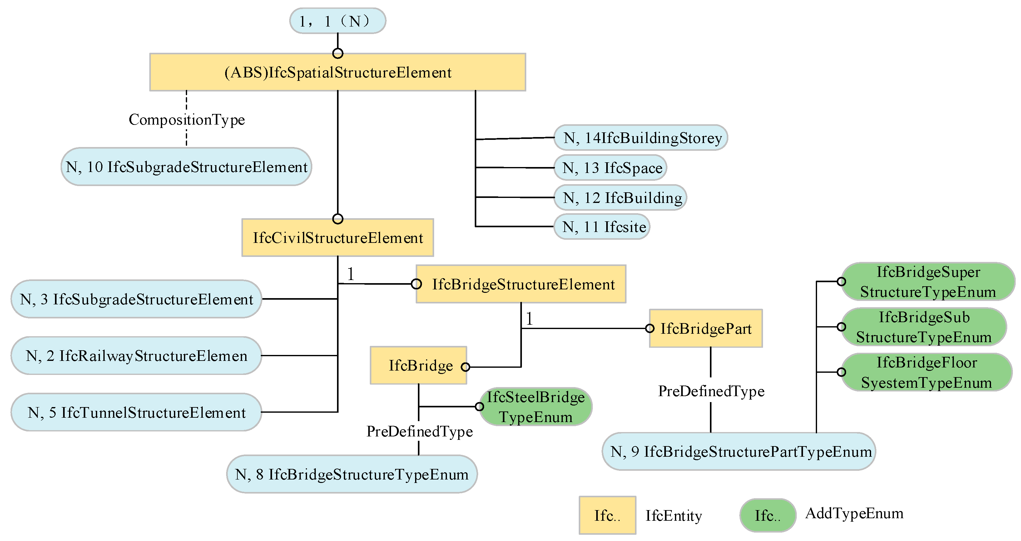
In the architectural domain, entities such as IfcBuilding and IfcBuildingStorey are commonly recognized as spatial structure elements, serving to organize the hierarchical spatial composition of buildings. Drawing an analogy to this organizational paradigm, a construction site or section within a bridge engineering project may likewise be defined as a spatial structure unit, which can be further decomposed into IfcBridgePart and IfcBridgeElement components. Within the IFC4 standard, specialized spatial entities—including roads, bridges, and tunnels—are modeled using IfcSpatialElement, which enables the semantic representation of spatial characteristics across diverse infrastructure types. The inheritance relationships among bridge-related spatial structure elements are illustrated in Figure 5.
Beginning with the base entity IfcCivilStructureElement, the spatial structure unit for bridge engineering, IfcBridgeStructureElement, is introduced as the parent class of all spatial models in bridge projects. This class is further specialized into two subclasses: IfcBridge, representing the overall bridge structure, and IfcBridgePart, representing individual components such as piers, towers, and main girders. The IfcBridgePart entity denotes the primary structural units of a bridge, typically corresponding to construction segments like piers, towers, or continuous girders. In contrast, IfcBridgeElement captures finer-grained structural elements within these parts, including, for instance, main girder segments or steel box girder sections.
In addition, the IFC schema provides the enumeration IfcBridgeStructureTypeEnum, which categorizes bridge types such as GIRDERBRIDGE, STEELBRIDGE, ARCHBRIDGE, CABLESTAYEDBRIDGE, and SUSPENSIONBRIDGE. For more refined classification, IfcBridgeStructurePartTypeEnum further decomposes bridge elements into subtypes such as IfcBridgeSuperStructurePartTypeEnum (superstructure), IfcBridgeSubStructurePartTypeEnum (substructure), and IfcBridgeFloorSystemTypeEnum (deck system), thereby enhancing semantic clarity and modeling granularity. The aggregation relationship between IfcBridge and IfcBridgePart is formally established using IfcRelAggregates, ensuring both semantic completeness and extensibility of the spatial structure model.

4.1.2. Steel Bridge Components

Bridge components serve as the fundamental constituents of both spatial structure units and assemblies, requiring well-defined physical attributes and constructability. These components must be semantically modeled with a comprehensive consideration of their functional roles, geometric characteristics, and engineering significance to ensure both completeness and consistency across the model. As illustrated in Figure 6, each component is organized within a clear inheritance and aggregation hierarchy, established according to its functional differentiation and the logic of the structural system.
In the component-level modeling framework proposed in this study, the entity IfcBridgeElement is derived from IfcCivilElement and serves as the superclass for all structural components within bridge engineering projects. Based on the functional semantics of components and the hierarchical decomposition logic of bridge spatial structures, a series of representative steel bridge components have been extended and defined as specialized entity classes.

4.1.3. Assembly Units of Steel Bridges

Assemblies represent composite structural units composed of multiple individual components. While semantically categorized under components, they are often defined as separate assembly classes in BIM modeling to emphasize their structural characteristics derived from the aggregation of subcomponents. Within the IFC static extension strategy, assembly-related entities are derived from the base class IfcElement. Their modeling can reference the organizational structure of the general assembly entity IfcElementAssembly to establish a comprehensive representation system tailored for bridge engineering assemblies. The inheritance structure of bridge assemblies is illustrated in Figure 7.
To support the modeling of infrastructure assemblies, the generalized civil component class IfcCivilElement is first extended to define an intermediate class IfcCivilElementAssembly. This class serves as a foundational structure for infrastructure-specific assembly entities. Building upon this, the study introduces a domain-specific entity, IfcBridgeElementAssembly, tailored to organize and manage all types of composite bridge assemblies. To accommodate the intricate nature of bridge structures, IfcBridgeElementAssembly is further specialized into a set of commonly used bridge assembly types, including IfcBridgeTruss, IfcBridgeJoint, IfcBeamFallingPreventionDevice, and IfcCrossBrace.
Although the IFC4 standard defines Truss as an enumeration item under IfcElementAssemblyTypeEnum, such a classification merely offers a semantic label without enabling detailed modeling of the truss as a distinct entity. In practical bridge engineering, trusses often serve as primary load-bearing components characterized by complex geometries and diverse structural configurations. Enumeration-based classification alone is insufficient to represent their semantic logic, structural topology, and parametric attributes. Hence, this study proposes a dedicated entity, IfcBridgeTruss, to enhance semantic clarity and improve the expressiveness of truss structures within bridge information modeling.

4.1.4. Bridge Part Components

IfcElementComponent refers to small-scale structural elements that are either affixed to the surface of primary components or embedded within them, typically serving auxiliary functions such as reinforcement or connection. In building information modeling, various fasteners (e.g., IfcFastener) and connecting accessories are representative examples of such parts. Within the IFC standard framework, a broad spectrum of component parts is represented through IfcElementComponent and its subclasses. For instance, typical detailing components in steel bridges—such as welds—can be formally expressed using IfcFastener with the enumeration type WELD. Meanwhile, mechanical connectors (e.g., bolts and shear studs) are modeled through the subclass IfcMechanicalFastener, using specific types such as BOLT and STUDSHEARCONNECTOR to capture their distinct roles in assembly and load transfer.

4.2. Steel Bridge Entity Expansion and Representation Based on IFC Standards

In accordance with the ISO 12006-2 framework and the Classification and Coding Standard for Railway Engineering Information Models (based on the International Framework for Dictionaries, IFD standard), this study assigns a unique type code to each bridge component concept and term [37]. A multi-dimensional classification system is established based on function, morphology, construction technique, and structural characteristics. The standard categorizes bridge components into five hierarchical levels, thereby ensuring semantic consistency and structural clarity during cross-phase information transmission. Aligned with the information organization logic of the design, fabrication, and construction phases of bridge projects, this study adopts a static extension approach to semantically enhance the relevant IFC entities pertaining to the bridge and railway domains. The resulting hierarchical system reflects a top-down semantic organization, with its inheritance structure and aggregation logic illustrated in Figure 8.
In this hierarchical framework, the fundamental component units—termed elementary components—are defined using a unified modeling approach. Through inheritance and nested aggregation mechanisms, a multi-level assembly system is constructed to accommodate the complex interrelations and information integration requirements of bridge engineering projects.
To ensure that the model information generated during the design phase of steel bridges remains consistent with the demands of engineering management in subsequent fabrication stages, this study develops a hierarchical extension of the bridge information model. The proposed structure aligns with four levels of abstraction: Spatial Structure Elements (IfcSpatialStructureElement), Assemblies (IfcElementAssembly), Components (IfcCivilElement), and Parts (IfcElementComponent). All extended entities are derived from subclasses of the general product type IfcProduct, thereby ensuring semantic consistency and model recognizability within the IFC framework.
Specifically, the bridge spatial structural unit IfcBridgeStructureElement, designed to organize spatial elements in the bridge domain, inherits from the spatial base class IfcSpatialStructureElement. On this basis, two specialized entities—IfcSteelBridge (representing the entire steel bridge structure) and IfcSteelBridgePart (representing its constituent components)—are further derived. These entities are semantically linked through the aggregation relationship entity IfcRelAggregates, enabling structured composition and logical organization within the extended IFC schema.
In practical engineering applications, a single bridge site may encompass multiple structural types, such as cable-stayed steel bridges, continuous steel box girder bridges, and simply supported beam bridges. When IfcBridge is used to represent an individual bridge of a single structural type, its CompositionType attribute—derived from IfcSpatialStructureElement—should be set to ELEMENT. Conversely, if it is intended to represent a composite bridge system comprising multiple structural types, the CompositionType should be designated as COMPLEX, thereby accurately capturing the integrated nature of its structural configuration.

4.3. Extension and Expression of Property Sets for Steel Bridge Entities Based on the IFC Standard

Despite the support of predefined property sets in existing IFC entities, significant limitations remain in addressing the information requirements of steel bridge components across their full lifecycle—particularly in structural analysis, fabrication, and maintenance phases. To enable more refined modeling and semantic representation of steel components, this study introduces tailored extensions to both entity modeling and property sets for key elements of steel bridges. These enhancements support object definition, semantic annotation, and data storage in multi-phase BIM environments for structural engineers.
The extended property sets are designed to fulfill information integration needs during the design and fabrication stages, with a focus on spatial configuration, functional performance, and manufacturing processes. To improve the logical clarity and semantic consistency of property organization, the properties are classified into three distinct sets:
  • Pset_BridgeElementIdentificationCommon, encompassing general identity attributes such as name, tag, and component code;
  • Pset_SteelBridgeComponentDesign, which captures technical design parameters including section type, geometric dimensions, load class, and connection method;
  • Pset_SteelBridgeComponentFabrication, describing manufacturing execution data such as fabrication techniques, welding specifications, prefabricated part codes, and installation orientation.
The data structures of these three property sets correspond to Table 1, Table 2, and Table 3, respectively.
Within the IFC modeling framework, the expression of entity attributes is realized through association mechanisms that link property sets to specific components. As illustrated in Figure 9, extended material and attribute information are associated with the target elements via the entities IfcRelAssociatesMaterial and IfcRelDefinesByProperties, respectively. The IfcRelAssociates entity facilitates the connection between components and their corresponding material definitions (IfcMaterial) or property sets (IfcPropertySet), thereby enabling the enrichment of component data with attributes such as material specifications, identification codes, cross-sectional designations, and surface treatment details.
The modeling process for custom property sets is structured around the IfcPropertySetDefinition entity. Initially, individual properties are defined using entities such as IfcPropertySingleValue. These discrete properties are then aggregated into a complete property set (IfcPropertySet), which is assigned a standardized name. Subsequently, the property set is associated with the target component—such as Pset_SteelBridgeComponentDesign or Pset_SteelBridgeComponentFabrication—via the IfcRelDefinesByProperties entity. The component, now enriched with its associated property set, is then linked to its corresponding spatial structural unit through the IfcRelContainedInSpatialStructure relationship. In cases where the component is part of a larger assembly, the IfcRelAggregates entity is first employed to establish the aggregation relationship with its parent assembly. Only thereafter is the component spatially integrated into the overall bridge model structure.
Moreover, each IFC component must incorporate two fundamental attributes: ObjectPlacement (spatial positioning) and Representation (geometric description). The ObjectPlacement attribute references the IfcLocalPlacement entity and utilizes the PlacementRelTo and RelativePlacement properties to define the reference coordinate system and the component’s local coordinate system, respectively. The Representation attribute specifies the geometric configuration of the component.
In terms of geometric representation, components with regular geometry are typically modeled using the SweptSolid approach. This method employs the IfcExtrudedAreaSolid entity to extrude a two-dimensional profile along a defined direction, thereby generating a three-dimensional solid. For components featuring complex geometric characteristics—such as steel beams with fillets at the junctions between the flange and web—the CSG (Constructive Solid Geometry) method is often adopted. This involves using the IfcBooleanResult entity to perform Boolean operations among primitive solids to construct intricate geometries.
Cross-sectional profiles are defined using the IfcProfileDef entity structure. For I-shaped sections, the subclass IfcIShapeProfileDef can be employed to facilitate parametric definition.

5. Steel Bridge Information Model Extension and Modeling Based on the 3DEXPERIENCE Platform

5.1. IFC Data Extension Workflow Based on the 3DEXPERIENCE Platform

The IFC extensions proposed in this study are designed to enhance the object modeling and semantic representation capabilities of the IFC standard within the AEC domain. Building upon the foundational data structure for steel bridge information modeling presented in previous sections, this chapter focuses on how to implement customized deployment and semantic enrichment of steel bridge BIM models on the 3DEXPERIENCE platform using IFC extension mechanisms.
The 3DEXPERIENCE platform (version R2021x), developed by Dassault Systèmes, is an integrated digital engineering environment that supports multidisciplinary collaboration, lifecycle management, and complex structural modeling. In the context of irregular steel bridge projects, where structural complexity and non-standardized components are prevalent, conventional IFC models often fall short in providing adequate semantic representation and information organization. Therefore, it becomes essential to tailor and extend the IFC model in alignment with the specific characteristics and design logic of engineering components to ensure greater data consistency and interoperability.
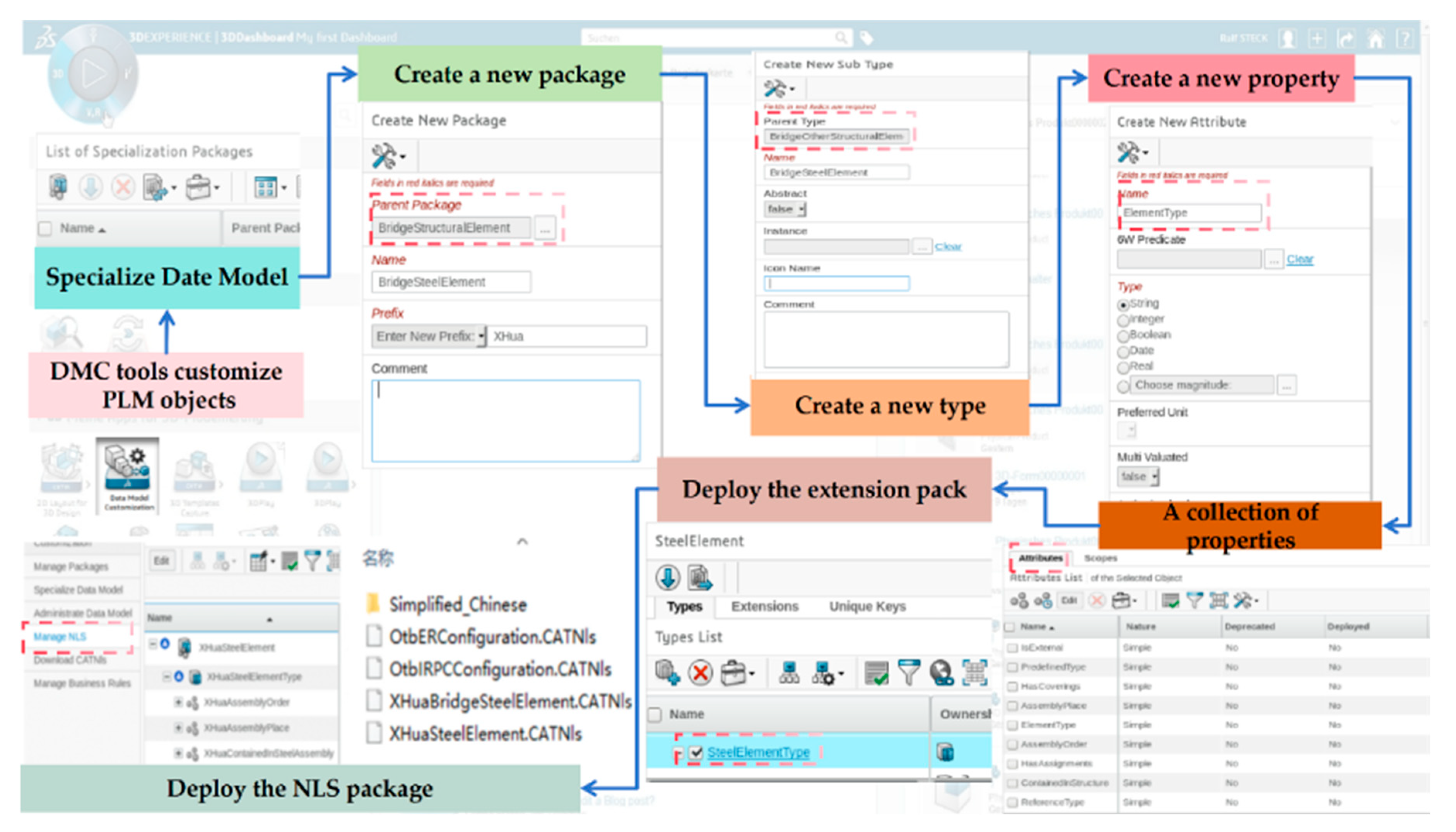
The core module responsible for implementing IFC extensions and enabling cross-system interoperability within the platform is the Technical XML Output (TXO) module. TXO facilitates object model customization, property set definition, and XML/IFC data export, providing unified data services to applications such as CATIA and ENOVIA. This study achieves refined modeling and customized deployment of steel bridge IFC objects within the 3DEXPERIENCE platform. The implementation workflow is illustrated in Figure 10, and comprises the following steps:
  • DMC Tools Customize PLM Objects: Using the DMC (Data Model Customization) module, domain-specific extended entities such as bridge components are created by inheriting and customizing base PLM types, enabling tailored expansion of the model structure.
  • Specialize Data Model: The customized objects are further structured into a hierarchical semantic data model tailored for steel bridges. For example, specialized component classes such as IfcSteelBoxGirder and IfcStiffener are defined, along with their assembly logic and geometric semantics.
  • Create a New Package: A dedicated extension package is created via the platform configuration tools. The package includes versioning, namespace assignment, and inheritance paths to encapsulate all definitions of extended objects, properties, and associated resources.
  • Create a New Type: Within the extension package, specific IFC extension types—such as IfcSteelBoxGirder (inheriting from IfcBeam)—are registered. Each type is configured with an icon, description, export status, and multilingual support.
  • Add New Property: Identification, design, fabrication, and maintenance-related property fields are defined for each extended object. These fields support a variety of data types, including enumerations, Boolean, and string types, thereby enhancing semantic expressiveness.
  • A Collection of Properties: Multiple property fields are grouped into standardized property sets (IfcPropertySet), each with clearly defined application scopes and export control rules to ensure consistent semantic interpretation across platforms.
  • Deploy the Extension Pack: The extension package is deployed to the TXO (Technical XML Output) module and registered, enabling integrated access and utilization of the extended model by platform tools such as CATIA and ENOVIA.
  • Deploy the NLS Package: A multilingual National Language Support (NLS) package is released to guarantee accurate understanding and application of the extended model in diverse linguistic environments.
Through this systematic workflow, the study establishes a semantically enriched, structurally coherent, and platform-recognizable IFC extension model for steel bridges. The model is successfully deployed within the 3DEXPERIENCE environment, achieving cross-platform data consistency and interoperability. This provides a clear and actionable pathway for implementing BIM applications in complex steel bridge engineering projects.

5.2. Information Modeling Workflow for Steel Bridges

In this study, the IFC standard plays a pivotal role in addressing the challenge of data interoperability among heterogeneous BIM software systems. By integrating the TXO module within the 3DEXPERIENCE platform and the CATIA modeling tool, a comprehensive information model tailored to the full lifecycle of steel bridges is constructed. This model systematically extends both the semantic structure and geometric representation, ensuring that the newly defined entities and property sets are recognizable, readable, and analyzable across various BIM platforms. This integration significantly enhances data exchange efficiency and semantic consistency.
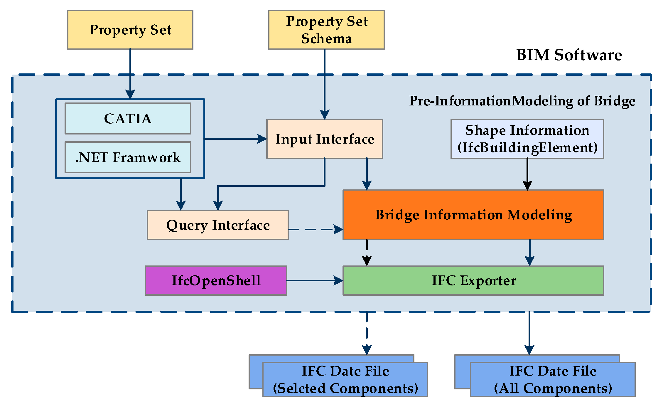
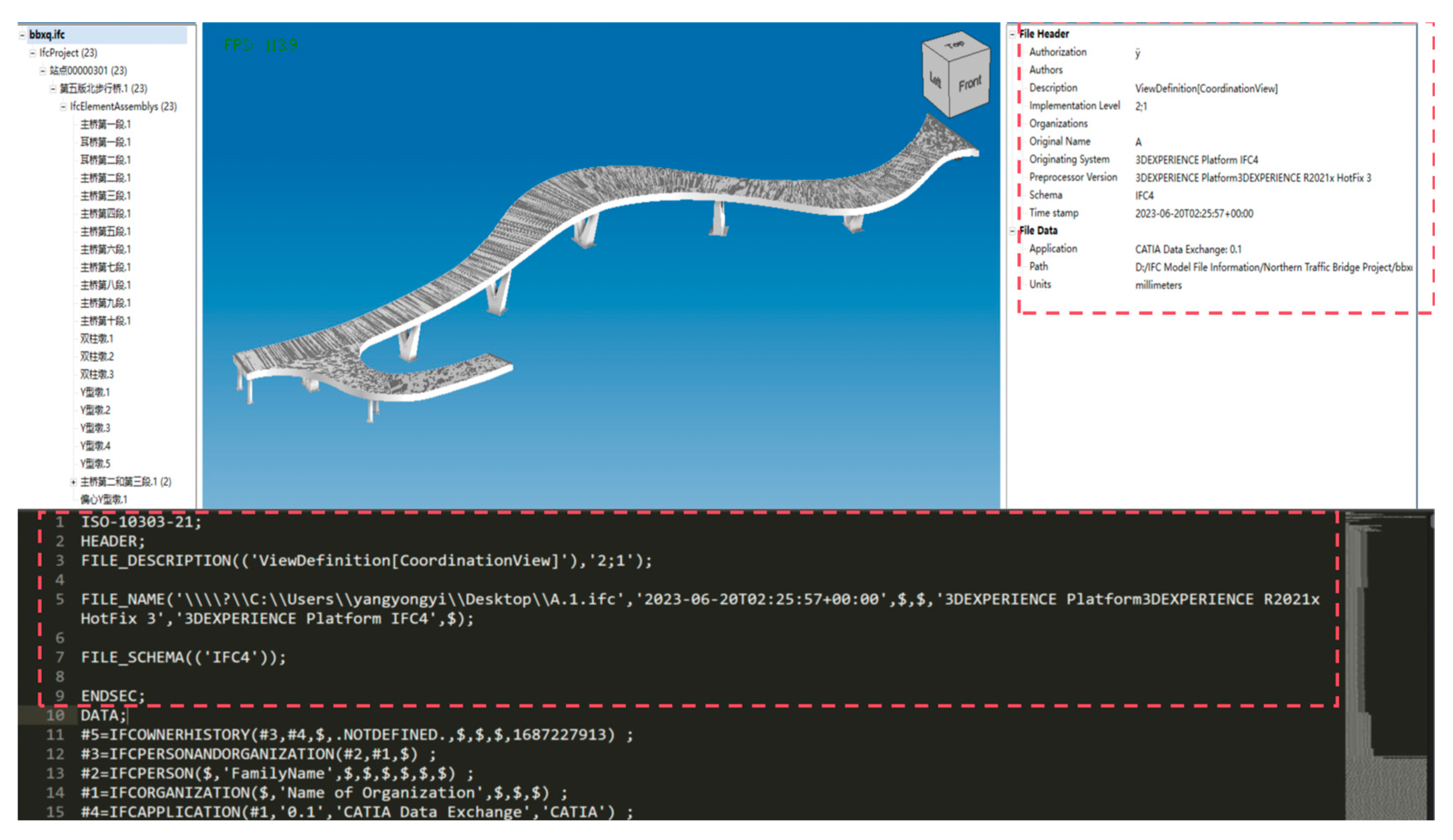
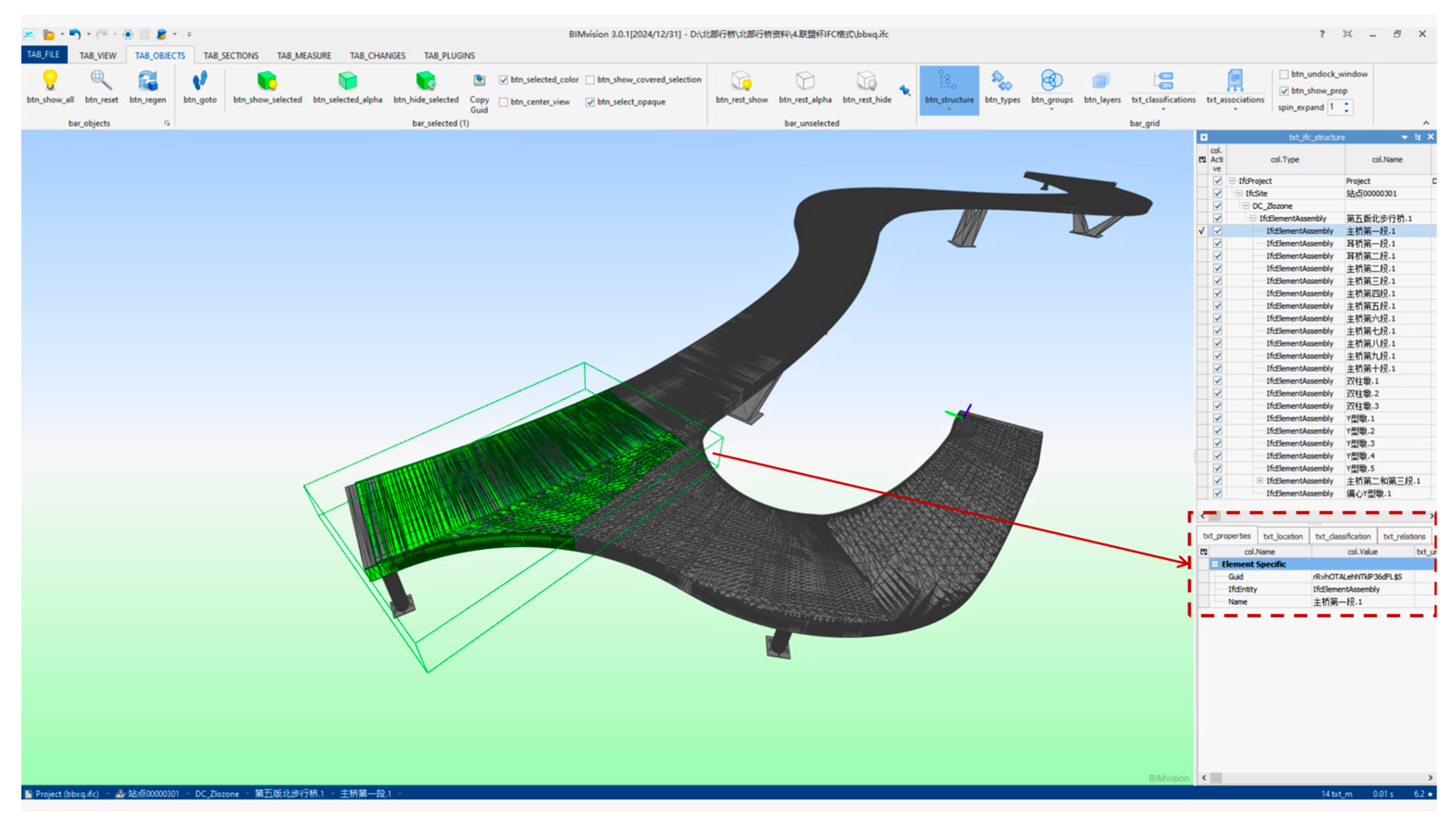
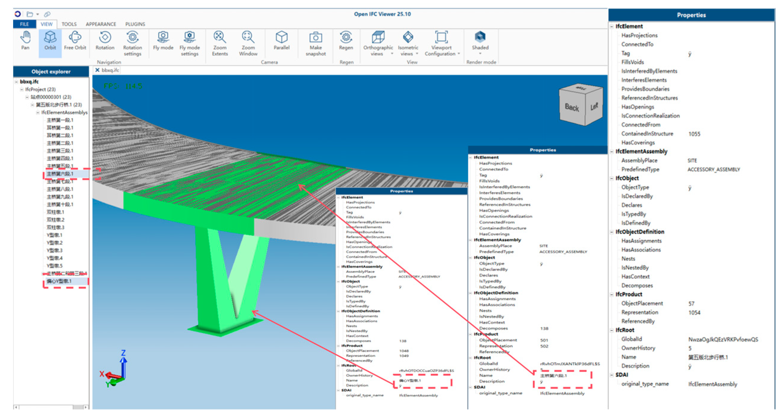
To validate the effectiveness of the extended IFC model, the IfcOpenShell toolkit is employed to export the geometric components and semantic properties into standard IFC-format files. These files are subsequently tested on multiple platforms, including BIMvision, usBIM, and OpenIFCViewer. The results demonstrate that the exported IFC models exhibit robust semantic expressiveness and comprehensive information integrity, effectively supporting cross-platform data sharing and interoperability requirements. Based on the proposed extended IFC model for bridge engineering, this study further formulates a comprehensive steel bridge information modeling workflow, as illustrated in Figure 11:
  • Geometry Modeling: Parametric geometric modeling of steel bridge components—such as main girders, webs, diaphragms, and stiffeners—is carried out using the CATIA platform. This step enhances the modularity and reusability of the model components.
  • Attribute Injection: Design and fabrication stage attributes are embedded into the components via PartProperties and User Defined Feature (UDF) templates. The Engineering Knowledge Language (EKL) scripting mechanism is employed to enable automated value assignment, conditional logic, and inter-property linkage.
  • IFC-Based Semantic Extension: Using TXO and DMC tools, native IFC entities (e.g., IfcBeam, IfcPlate) are extended to define bridge-specific subclasses (e.g., IfcSteelGirder, IfcStiffener), which are then linked to corresponding customized property sets (IfcPropertySet).
  • Model Assembly: In accordance with the semantic decomposition structure defined by the IFC 4 × 3 standard for bridges, the extended components are systematically assembled into a complete IFC project structure, ensuring consistent multi-level representation.
  • IFC Export & Verification: The extended bridge model is exported to the .ifc format using IfcOpenShell. Its semantic expressiveness and cross-platform compatibility are subsequently validated through testing on BIM platforms such as BIMvision, usBIM, and OpenIFCViewer.
This workflow ensures that the semantic depth, geometric fidelity, and information continuity of the steel bridge model are rigorously preserved throughout the entire design-to-fabrication pipeline. The loading performance of the exported model across the aforementioned platforms is illustrated in Figure 12 and Figure 13. The results demonstrate that each platform can accurately interpret the extended semantic tree structure of the components, the associated property sets, and the geometric representations. This study further confirms that the method of introducing new entities via modifications to the EXPRESS schema can be correctly parsed by mainstream platforms, with all semantic attributes of the extended components being comprehensively expressed.

6. Case Study

6.1. Case Overview and Modeling Results

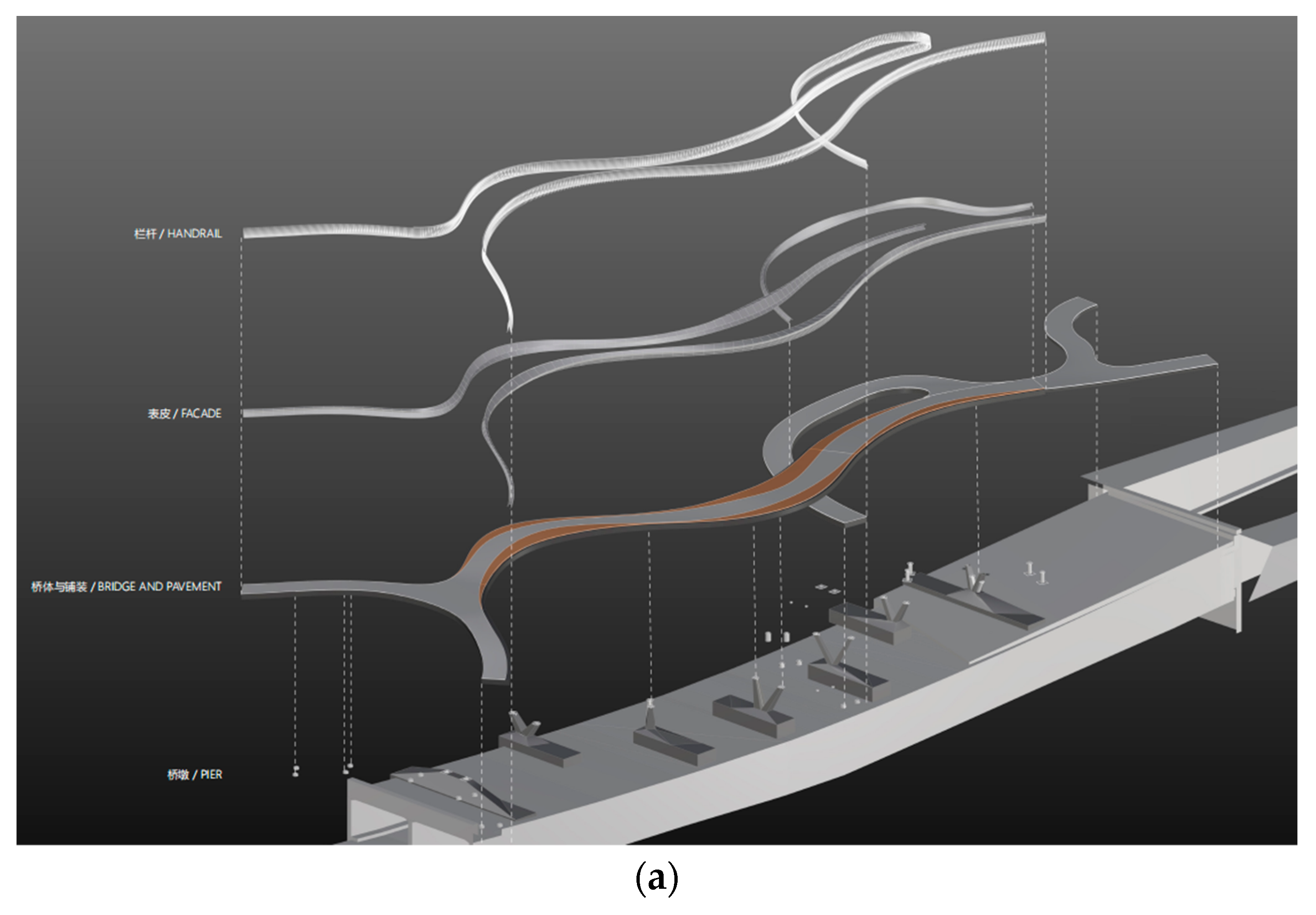
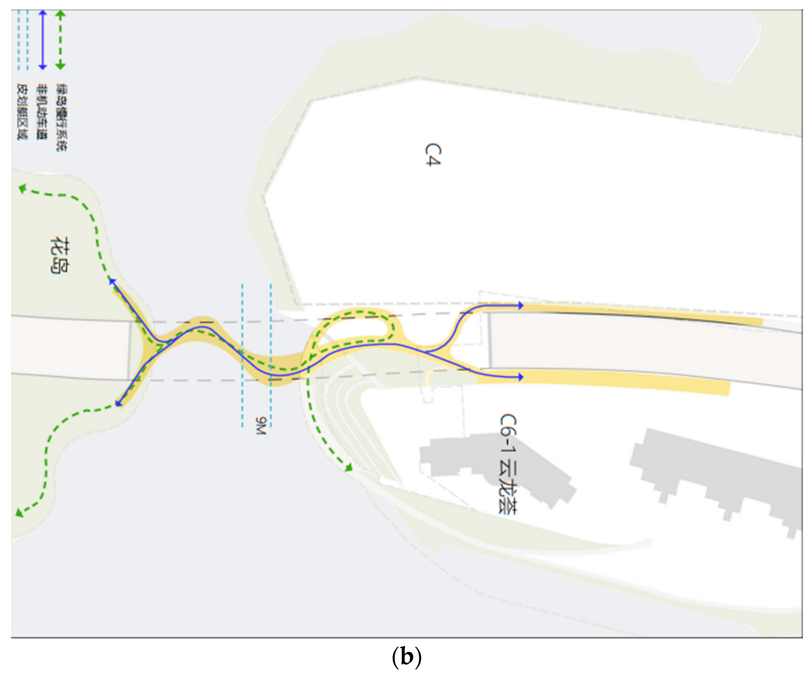
The case study selected for this research is the Q7 North Pedestrian Bridge, a key regional infrastructure project in China, serving as a verification example. As one of the major supporting facilities for the canoeing events of the 31st FISU World University Games held in Chengdu, the bridge adopts a spatially twisted steel structure scheme, characterized by its complex geometry and high-performance requirements. This endows the project with strong engineering representativeness and significant research value for broader application. The conceptual design of the Q7 Bridge was developed by the Australian firm Cox Architecture, as illustrated in Figure 14. The overall project comprises three main sections: the main bridge, the flanking (ear) bridges, and the elevated Huadao Bridge, encompassing two distinct structural systems—bridge spans and overhead segments.
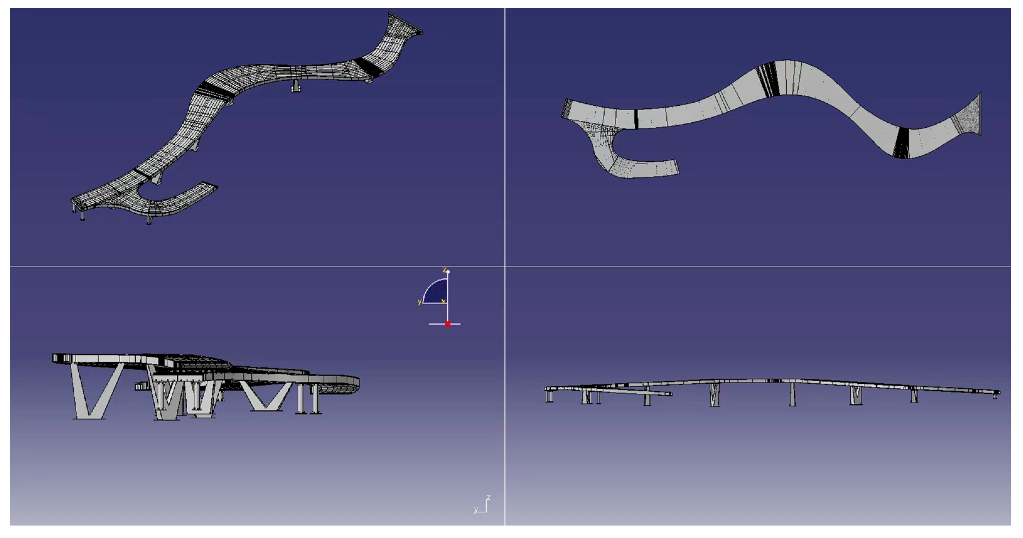
The horizontal alignment of the bridge structure exhibits significant overlap with the existing tunnel foundation system. Several piers and elevated segments are positioned and reinforced based on the tunnel foundation, resulting in a complex structural dependency. This unconventional steel bridge scheme exemplifies the integrated application of BIM-based steel structure modeling and the digital fabrication of customized components throughout the design and construction stages. In particular, the semantic definition of components and assembly modeling imposed practical demands for extending the IFC schema, thereby offering a representative validation scenario for the IFC extension framework proposed in this study. The bridge model developed in CATIA is illustrated in Figure 15.

6.2. Display of Component-to-IFC Matching Results

In the process of IFC-based bridge modeling, this study selects the steel box girder segments (superstructure) and pier segments (substructure) as representative components to define their semantic hierarchies, geometric configurations, and topological relationships. To achieve this, the object-oriented modeling mechanism of the EXPRESS language is employed to construct the structural framework of component assemblies. The IfcElementAssembly entity is adopted as the core representation of steel component groups, within which the component composition, spatial positioning, and associated attribute information are explicitly defined. A detailed comparison and verification of the extended IFC entities and their associated property sets are conducted to ensure that all newly introduced content conforms to the semantic structure of the IFC schema at the data level. This includes validation of entity hierarchies, relationship mappings, and data consistency, as well as the correct parsing and interpretation of information embedded within the IFC files.
The applicability of the proposed IFC extension model—developed through EXPRESS-based entity definition and property set injection—is rigorously tested in the context of modeling complex structural components. The results demonstrate a significant enhancement in both the semantic expressiveness and the collaborative efficiency across platforms. As shown in Figure 16, the original IFC file—prior to extension—classified steel structures and other critical components under IfcBuildingElementProxy, lacking precise semantic representation. In contrast, the extended version incorporates the newly defined steel bridge entity IfcElementAssembly along with its associated property sets directly into the IFC file. As illustrated in Figure 17, the extracted IFC data confirms the proper representation of the entities and their attribute sets.
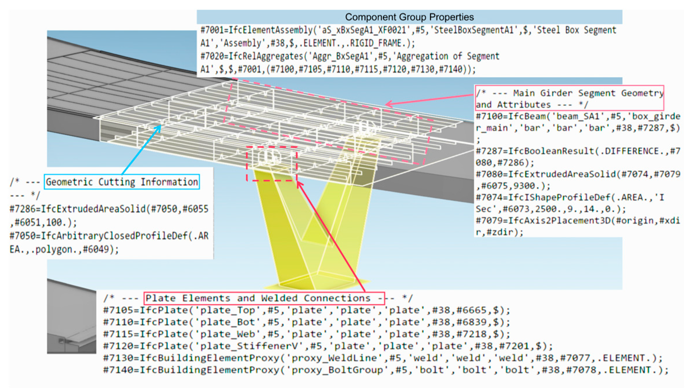
Grouping information comprises both component groups and node groups. When components are grouped, the subcomponents within each group are associated as a unified entity, forming the fundamental unit for fabrication and transportation within steel fabrication plants. This grouping approach plays a critical role in detailed design and construction management. The Steel Box Girder Segment is defined as a structural assembly composed of multiple subcomponents. Within this assembly, the main girder elements are represented using the IfcBeam entity, whose 3D geometry is constructed through a combination of IfcExtrudedAreaSolid for extrusion-based solids and IfcBooleanResult for Boolean operations, enabling accurate representation of intricate details such as notches, perforations, and chamfers.
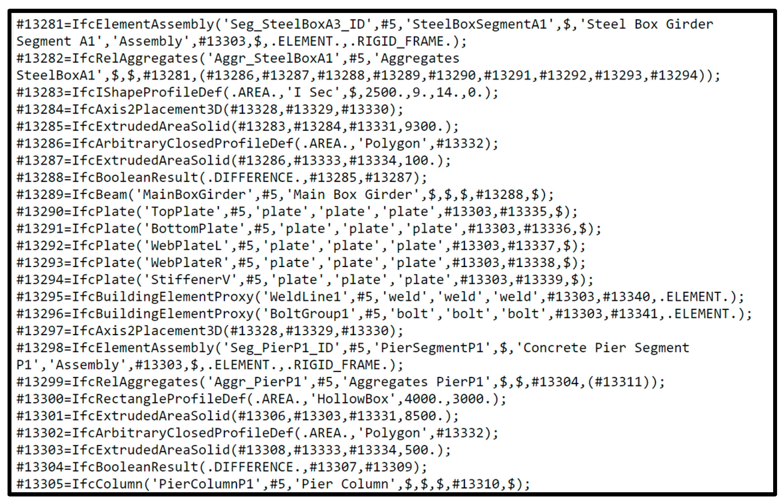
Various plates forming the girder—such as top plates, bottom plates, webs, and stiffeners—are uniformly modeled using the IfcPlate entity. Auxiliary elements, including welds and bolt groups, are abstractly represented by IfcBuildingElementProxy, and are aggregated with the main girder component via the IfcRelAggregates entity, thereby forming a complete structural representation system. As the core structural group supporting the system, the pier segment is similarly modeled based on the IfcElementAssembly entity, with the pier shaft represented by IfcColumn. The geometric modeling of the pier shaft employs a combination of extrusion and Boolean operations, where the fundamental shape (rectangular or circular cross-section) is defined by IfcExtrudedAreaSolid, and local features such as openings and chamfers are refined using IfcBooleanResult. This approach enables precise representation of both structural performance and construction process requirements. The complete IFC data structure of the component models is illustrated in Figure 18 and Figure 19.
The topological connection between the steel box girder segments and pier segments is critical for explicitly defining the structural load transfer path. In this study, the compositional logic and load-bearing relationships among components are explicitly represented using IfcRelAggregates (aggregation relationships) and IfcRelConnectsStructuralMember (structural connection relationships), as illustrated in Figure 20 and Figure 21. In this configuration, the pier segment is treated as the subordinate structural element that aggregates the overlying steel box girder segment, thereby clearly articulating the direction of structural support and the sequential order of assembly. This data structure provides a logically consistent foundation for subsequent construction simulation, structural analysis, and maintenance management. The spatial positioning of each component is defined through a unified local coordinate system using IfcAxis2Placement3D. Meanwhile, key parameters—such as component name, material type, cross-sectional dimensions, fabrication processes, and weld grades—are associated with corresponding property sets via the IfcRelDefinesByProperties entity. This approach ensures both the completeness of the model’s information content and its interoperability across platforms.
In summary, the proposed IFC extension model for grouped steel bridge components enables a systematic representation of spatial topological relationships, geometric features, and component assembly logic. It thus establishes a comprehensive and reusable data framework that supports refined information modeling and full lifecycle digital management for steel bridge engineering projects.
The parametric performance of the proposed model constitutes a central focus of this study. To systematically assess the data interoperability of different platforms, three mainstream structural design software packages with IFC export functionality—Tekla, Revit, and ArchiCAD—were selected. The exported IFC models were subjected to statistical analysis of data conversion rates, and the comparative results are presented in Table 4.
As shown, in comparison with the other three BIM platforms, the 3DEXPERIENCE IFC export technology, which natively integrates the proposed IFC extension scheme, achieved superior conversion rates for geometric data such as entity segmentation and local coordinate systems. Moreover, by incorporating parametric grouping information and extended component attributes, it enriched the variety of exportable data, thereby demonstrating a distinct advantage in information conversion. Tekla, as a domain-specific software for detailed steel structure design, exhibited excellent performance in both geometry and most attribute conversions, reaffirming its recognized specialization in this field. Nonetheless, its retention rate for parametric grouping and cutting information was slightly lower than that of 3DEXPERIENCE, primarily because the extended semantics defined in this study (e.g., manufacturing-oriented property sets) exceeded its native capabilities. This limitation, in turn, underscores the academic and practical value of pursuing IFC standard extensions. By contrast, Revit and ArchiCAD, as general-purpose platforms in the architectural domain, displayed limited support for complex and customized semantics of steel structures due to constraints in their native IFC processors.
From the perspective of computational efficiency, the Q7 North Pedestrian Bridge model was selected as a case study. The original DWG file measured 84.8 MB, comprising 6205 plates, 953 bolts, 1482 welds, and 3784 node groups. Following conversion via the 3DEXPERIENCE export technology, the resulting IFC file size was 156 MB, with an export time of 2 min 43 s. The subsequent import times were 3 min 36 s in Revit, 1 min 37 s in ArchiCAD, and 3 min 12 s in Tekla (via a dedicated data interface). These results highlight the superior spatial performance and runtime efficiency of the full-data interoperability approach proposed in this study.

7. Conclusions

To advance the digital construction of steel bridge engineering and enhance the efficiency of information exchange and data sharing between the design and manufacturing stages, this study proposes a hierarchical IFC semantic extension framework tailored to the design–manufacturing integration process. Unlike prior approaches that typically focus on a single stage (e.g., design or construction), the proposed framework not only extends entity definitions but also establishes a systematic, multi-tiered semantic architecture aligned with engineering logic and manufacturing workflows. This enables coherent information transmission from macro-structural units to micro-level parts. The main conclusions are as follows:
(1)
Leveraging the EXPRESS language of the IFC standard and its EXPRESS-G diagrammatic representation, a multi-level semantic model covering spatial structure units, components, assemblies, and parts was developed. This significantly strengthens the consistency and semantic completeness of BIM data representation across design, manufacturing, and assembly stages.
(2)
On the 3DEXPERIENCE platform, the integration of the TXO module and DMC tools enabled the implementation of extended IFC entity definitions and their system-level deployment. Standardized export of geometric and attribute information was achieved via IfcOpenShell. Cross-platform validation in CATIA, BIMvision, and usBIM environments demonstrated efficient sharing, accurate parsing, and robust interoperability, thereby confirming the strong engineering applicability and practical value of the proposed method.
(3)
The proposed BIM modeling approach provides a systematic solution for the digital design and delivery of complex steel bridge projects. It effectively alleviates inconsistencies and inefficiencies in multi-disciplinary collaboration and cross-stage data transfer. The research outcomes carry substantial theoretical significance and engineering value for promoting BIM standardization in steel bridge projects, supporting industry-wide digital transformation, and enhancing full lifecycle management.
Despite these contributions, the study has certain limitations. The current extension mechanism is primarily focused on static attributes in the design and manufacturing stages, without fully integrating dynamic information from construction and operation phases (e.g., real-time monitoring data or progress–cost information). Furthermore, while EXPRESS Schema-based entity extensions improve semantic precision, they also introduce potential compatibility risks, as limited support for custom entities on some platforms may result in semantic information loss. Contributing to the development of international standards such as IFC-Bridge, promoting the proposed framework as a widely accepted best practice, and exploring its applicability to other bridge types (e.g., arch bridges, suspension bridges) and complex steel structures. Exploring AI-driven and rule-based approaches are necessary to develop functions such as automated compliance checking, process optimization, and construction scenario generation, thereby further advancing the level of digital and intelligent management in steel bridge engineering.

Author Contributions

Conceptualization, Y.Y. and J.X.; methodology, J.X.; software, Y.Y. and Z.Z.; validation, J.X., Y.Y. and Z.Z.; formal analysis, J.X. and Z.Z.; investigation, J.X.; resources, Y.Y.; data curation, J.X.; writing—original draft preparation, J.X.; writing—review and editing, J.X.; visualization, J.X.; supervision, Y.Y. and Z.Z.; project administration, J.X. and Z.Z.; funding acquisition, Y.Y. All authors have read and agreed to the published version of the manuscript.

Funding

This research was funded by the Yunnan Province Major Science and Technology Special Plan Project (No. 202302AD080009); Yunnan Provincial Science and Technology Plan Project (No. 202305AF150138); Yunnan Prov. Sci. & Tech. Spec. Plan, (No. 202102AD080003); National Natural Science Foundation of China (Grant No. 52378537).

Data Availability Statement

The original contributions presented in this study are included in the article. Further inquiries can be directed to the corresponding author.

Conflicts of Interest

Author Zizhen Zhang was employed by the company Kunming Atide Software Co., Ltd. The remaining authors declare that the research was conducted in the absence of any commercial or financial relationships that could be construed as a potential conflict of interest.

References

  1. Alizadehsalehi, S.; Hadavi, A.; Huang, J.C. From BIM to Extended Reality in AEC Industry. Autom. Constr. 2020, 116, 103254. [Google Scholar] [CrossRef]
  2. Sacks, R.; Koskela, L.; Dave, B.A.; Owen, R. Interaction of Lean and Building Information Modeling in Construction. J. Constr. Eng. Manag. 2010, 136, 968–980. [Google Scholar] [CrossRef]
  3. Criminale, A.; Langar, S. Challenges with BIM Implementation: A Review of Literature. In Proceedings of the 53 rd ASC Annual International Conference Proceedings, Seattle, WA, USA, 5–8 April 2017. [Google Scholar]
  4. Zhang, Q.L.; Tang, Z.H.; Man, Y.L. BIM Full Data-exchange Technology of Steel Structure Based on Industry Foundation Class Standard. J. TONGJI Univ. Sci. 2024, 52, 331–339. [Google Scholar]
  5. Li, X.; Xu, J.; Zhang, Q. Research on Construction Schedule Management Based on BIM Technology. Procedia Eng. 2017, 174, 657–667. [Google Scholar] [CrossRef]
  6. Gao, G.; Liu, Y.-S.; Wang, M.; Gu, M.; Yong, J.-H. A Query Expansion Method for Retrieving Online BIM Resources Based on Industry Foundation Classes. Autom. Constr. 2015, 56, 14–25. [Google Scholar] [CrossRef]
  7. Lai, H.H.; Deng, X.Y.; Liu, X.L. IFC-based BIM data sharing and exchange. CHINA Civ. Eng. J. 2018, 51, 121–128. [Google Scholar] [CrossRef]
  8. Amor, R. Analysis of the Evolving IFC Schema. In Proceedings of the 32nd CIB W78 Information Technology for Construction Conference (CIB W78 2015), Eindhoven, The Netherlands, 27–29 October 2015. [Google Scholar]
  9. ISO 16739-1:2024; Industry Foundation Classes (IFC) for Data Sharing in the Construction and Facility Management Industries Part 1: Data Schema. International Organization for Standardization: Geneva, Switzerland, 2024. Available online: https://www.iso.org/standard/84123.html (accessed on 28 July 2025).
  10. Liu, L.; Li, B.; Zlatanova, S.; Van Oosterom, P. Indoor Navigation Supported by the Industry Foundation Classes (IFC): A Survey. Autom. Constr. 2021, 121, 103436. [Google Scholar] [CrossRef]
  11. Vanlande, R.; Nicolle, C.; Cruz, C. IFC and Building Lifecycle Management. Autom. Constr. 2008, 18, 70–78. [Google Scholar] [CrossRef]
  12. Söbke, H.; Peralta, P.; Smarsly, K.; Armbruster, M. An IFC Schema Extension for BIM-Based Description of Wastewater Treatment Plants. Autom. Constr. 2021, 129, 103777. [Google Scholar] [CrossRef]
  13. Hossain, M.A.; Yeoh, J.K.W. BIM for Existing Buildings: Potential Opportunities and Barriers. IOP Conf. Ser. Mater. Sci. Eng. 2018, 371, 012051. [Google Scholar] [CrossRef]
  14. Eadie, R.; Browne, M.; Odeyinka, H.; McKeown, C.; McNiff, S. BIM Implementation throughout the UK Construction Project Lifecycle: An Analysis. Autom. Constr. 2013, 36, 145–151. [Google Scholar] [CrossRef]
  15. Industry Foundation Classes (IFC)—Building SMART International. Available online: https://www.buildingsmart.org/standards/bsi-standards/industry-foundation-classes/ (accessed on 28 July 2025).
  16. ISO 10303-11:2004; Industrial Automation Systems and Integration—Product Data Representation and Exchange Part 11: Description Methods: The EXPRESS Language Reference Manual. International Organization for Standardization: Geneva, Switzerland, 2004. Available online: https://www.iso.org/standard/38047.html (accessed on 28 July 2025).
  17. W3C Extensible Markup Language (XML). Available online: https://www.w3.org/TR/xml11/ (accessed on 28 July 2025).
  18. Lee, Y.-C.; Eastman, C.M.; Solihin, W. An Ontology-Based Approach for Developing Data Exchange Requirements and Model Views of Building Information Modeling. Adv. Eng. Inform. 2016, 30, 354–367. [Google Scholar] [CrossRef]
  19. Lee, S.-H.; Jeong, Y.-S. A System Integration Framework through Development of ISO 10303-Based Product Model for Steel Bridges. Autom. Constr. 2006, 15, 212–228. [Google Scholar] [CrossRef]
  20. Lee, S.H.; Park, S.I.; Park, K.Y. IFC property set-based approach for generating semantic information of steel box girder bridge components. KSCE J. Civ. Environ. Eng. Res. 2014, 34, 687–697. [Google Scholar] [CrossRef]
  21. Park, S.I.; Lee, S.-H.; Almasi, A.; Song, J.-H. Extended IFC-Based Strong Form Meshfree Collocation Analysis of a Bridge Structure. Autom. Constr. 2020, 119, 103364. [Google Scholar] [CrossRef]
  22. Ji, Y.; Borrmann, A.; Obergrieβer, M. Toward the Exchange of Parametric Bridge Models Using a Neutral Data Format. In Proceedings of the Computing in Civil Engineering, Miami, FL, USA, 19–22 June 2011; American Society of Civil Engineers: Reston, VA, USA, 2011; pp. 528–535. [Google Scholar]
  23. Lee, S.-H.; Kim, B.-G. IFC Extension for Road Structures and Digital Modeling. Procedia Eng. 2011, 14, 1037–1042. [Google Scholar] [CrossRef]
  24. Wu, J.; Chen, J.; Chen, G.; Wu, Z.; Zhong, Y.; Chen, B.; Ke, W.; Huang, J. Development of Data Integration and Sharing for Geotechnical Engineering Information Modeling Based on IFC. Adv. Civ. Eng. 2021, 2021, 8884864. [Google Scholar] [CrossRef]
  25. Zhu, H.X.; Xu, Z. Research on information collaboration and model construction for top-down design of prefabricated buildings. J. Graph. 2021, 42, 289–298. [Google Scholar]
  26. He, Q.; Jin, C.X.; Gao, T.C.; Wang, P. Research on BIM Model of Railway Track Structure Based on IFC Standard Extension. J. Graph. 2023, 44, 357–367. [Google Scholar]
  27. Yang, Y.; Li, J.; Zhang, Z.; Liu, Y. Research on Information Extension of Mountainous Rack Railway Engineering Based on IFC Standard. Sci. Rep. 2024, 14, 21557. [Google Scholar] [CrossRef]
  28. Zhang, S.; Zhang, S.; Wang, C.; Zhu, G.; Liu, H.; Wang, X. Extended IFC-Based Information Exchange for Construction Management of Roller-Compacted Concrete Dam. Autom. Constr. 2024, 163, 105427. [Google Scholar] [CrossRef]
  29. Wang, Q.; Li, J.; Yao, H.; Li, Z.; Jia, X. Research on IFC-Based Tunnel Monitoring Information Integration and Visual Warning Scheme. Buildings 2025, 15, 2221. [Google Scholar] [CrossRef]
  30. Zhang, Z.; Meng, X. IFC-based information exchange framework research and implementation between architectural and structural design. Build. Struct. 2024, 54, 149–154. [Google Scholar]
  31. Lai, H.; Deng, X. Interoperability Analysis of Ifc-Based Data Exchange between Heterogeneous Bim Software. J. Civ. Eng. Manag. 2018, 24, 537–555. [Google Scholar] [CrossRef]
  32. Bao, L.S.; An, P.L.; Wang, P.; Liang, W.; Yu, L. Research on Visualization of Bridge Safety Information Based on IFC. J. Shenyang Jianzhu Univ. Nat. Sci. 2022, 38, 682–689. [Google Scholar]
  33. Sheik, N.A.; Veelaert, P.; Deruyter, G. Exchanging Progress Information Using IFC-Based BIM for Automated Progress Monitoring. Buildings 2023, 13, 2390. [Google Scholar] [CrossRef]
  34. Seo, J.; Kim, I. Industry Foundation Classes-Based Approach for Managing and Using the Design Model and Planning Information in the Architectural Design. J. Asian Archit. Build. Eng. 2009, 8, 431–438. [Google Scholar] [CrossRef][Green Version]
  35. Zhiliang, M.; Zhenhua, W.; Wu, S.; Zhe, L. Application and Extension of the IFC Standard in Construction Cost Estimating for Tendering in China. Autom. Constr. 2011, 20, 196–204. [Google Scholar] [CrossRef]
  36. Liu, Y.; Li, M.; Wong, B.C.L.; Chan, C.M.; Cheng, J.C.P.; Gan, V.J.L. BIM-BVBS Integration with openBIM Standards for Automatic Prefabrication of Steel Reinforcement. Autom. Constr. 2021, 125, 103654. [Google Scholar] [CrossRef]
  37. China Railway BIM Alliance (CRBIM). Railway BIM Data Standard Version 1.0. China Railw. BIM Alliance 2016, 177. [Google Scholar] [CrossRef]
Figure 1. Extended Framework Diagram of the Bridge Engineering Information Model Based on IFC Standards.
Buildings 15 03376 g001
Figure 2. Core Data Architecture of the IFC-Extended Bridge Engineering Information Model.
Buildings 15 03376 g002
Figure 3. Hierarchical Entity Inheritance Framework for the Bridge Engineering Information Model.
Buildings 15 03376 g003
Figure 4. Entity Extension and Semantic Property Customization.
Buildings 15 03376 g004
Figure 5. EXPRESS-G Diagram of Steel Bridge Spatial Structure Units.
Buildings 15 03376 g005
Figure 6. Steel EXPRESS-G Diagram of Steel Bridge Components.
Buildings 15 03376 g006
Figure 7. EXPRESS-G Diagram of Steel Bridge Assemblies.
Buildings 15 03376 g007
Figure 8. IFC-Extended EXPRESS-G Diagram of the Bridge Engineering Information Model.
Buildings 15 03376 g008
Figure 9. Information Model of Steel Bridge Components Based on the IFC Standard.
Buildings 15 03376 g009
Figure 10. Extend the 3DE platform IFC object to define the deployment workflow.
Buildings 15 03376 g010
Figure 11. Basic Framework for IFC-based Bridge Information Modeling.
Buildings 15 03376 g011
Figure 12. Open IFC viewer bridge segment display model. (This diagram was generated by Open IFC Viewer. Version 24.3.0, URL: https://openifcviewer.com, accessed on 12 August 2025).
Buildings 15 03376 g012
Figure 13. The usBIM demonstrates recognition of the extended component semantic tree structure. (This diagram was generated by usBIM. Version 1.0.0.0, URL: https://www.accasoftware.com/en/ifc-viewer, accessed on 12 August 2025).
Buildings 15 03376 g013
Figure 14. Pedestrian Bridge Project Phases: (a) Conceptual Design; (b) Planning and Design.
Buildings 15 03376 g014aBuildings 15 03376 g014b
Figure 15. Three-view projection of the bridge model developed in CATIA.
Buildings 15 03376 g015
Figure 16. Attribute status of the steel bridge model prior to extension.
Buildings 15 03376 g016
Figure 17. Comprehensive display of the steel bridge model attributes after extension.
Buildings 15 03376 g017
Figure 18. Viewing Data of the Steel Box Girder Component Assembly.
Buildings 15 03376 g018
Figure 19. IFC Format Data Example of a Steel Bridge Component Assembly.
Buildings 15 03376 g019
Figure 20. Topological Base Data of the Component Assembly.
Buildings 15 03376 g020
Figure 21. IFC Format Data Example for the Spatial Coordinates of a Component.
Buildings 15 03376 g021
Table 1. Identity Information Property Set for Steel Bridge Components.
Attribute NameData TypeDescriptionExample
UniqueCodingIfcLableUnique identifier of the componentBXG001-A-001
NameIfcLableOfficial name of the componentSteel Box Girder
TypeDesignatorIfcLableSteel component type identifierBoxGirder_Type_A
ProductionLotIdIfcLableProduction Batch NumberLOT20240715
ProductionDateIfcLableManufacturing Date20220801
SerialNumberIfcLableSerial NumberSN000321
PieceMarkIfcLablePart Identification NumberBM-GZ-001-A
LocationNumbeIfcLableInstallation Location CodeSpan2-Girder3
InstallerIfcLableInstalled ByCDZX
InstallationDataIfcLableInstallation Date20220801
MaterialIfcLableMaterial TypeQ370qE
IntensityIfcPressureMeasureStrength Properties48 MPa
DensityIfcMassDensityMeasureDensity Information2420 kg/m3
ElasticModulusIfcPressureMeasureModulus of Elasticity35,300 MPa
PoissonRatioIfcLablePoisson’s Ratio0.16
DescriptionIfcLableDescription of the ComponentSteel Box Girder
The naming convention for this property set adheres to the IFC standard syntax, whereby the prefix “Pset_” is followed by the corresponding type designation.
Table 2. Design Information Property Set for Steel Bridge Components.
NameData TypeExplainExample
TypeIfcLableComponent TypeMain beam
SectionFormIfcLableCross-Section TypeCabinet type
LengthIfcLengthMeasureDesign Length of Component12,500 mm
WidthIfcLengthMeasureComponent Width2500 mm
HeightIfcLengthMeasureComponent Height1800 mm
ThicknessIfcLengthMeasureMain Plate Thickness16 mm
DesignDeflectionIfcLengthMeasureDeflection Control StandardL/600
CamberIfcLengthMeasureDesigned Camber80 mm
FatigueClassIfcLableFatigue Classification90 MPa
The naming convention for this property set adheres to the IFC standard syntax, whereby the prefix “Pset_” is followed by the corresponding type designation.
Table 3. Fabrication Property Set for Steel Bridge Components.
NameData TypeExplainExample
FabricationCodeIfcIdentifierFabrication Component IDGX-L1-001
WorkshopIDIfcLableWorkshop IDWKS-03
ProcessingDateIfcDateFabrication Date2024-07-16
NCProgramIfcURIReferenceNC Fabrication Filenc://gx-l1-001.nc
WeldingMethodIfcLableWelding ProcedureSubmerged Arc Welding
HoleConfigurationIfcLableHole Position ParametersΦ22@100 mm
CuttingMethodIfcLableCutting MethodCNC Plasma Cutting
SurfaceTreatmentIfcLableSurface Treatment MethodSa2.5 Sandblasting
CoatingTypeIfcLableCoating MethodEpoxy Intermediate Coating
QRCodeIfcURIReferenceQR Code Identifier for Componentqr://gx-l1001.png
The naming convention for this property set adheres to the IFC standard syntax, whereby the prefix “Pset_” is followed by the corresponding type designation.
Table 4. Test results of IFC formate data-exchange for different modeling softwares.
Evaluation MetricInformation Retention Rate of IFC Models Exported by Different Software/%
3DEXPERIENCETeklaRevitArchiCAD
Geometric Appearance100.00100.00100.00100.00
Spatial Positioning93.2578.541.0830.19
Component Sections93.2578.541.0830.19
Fabrication Cuts & Notches88.0371.2300
Attributes (Design/Fabrication)100.0070.156.42100
Parametric Group Information100.00100.00100.00
(Non-parametric)
0
Overall Retention Rate93.8583.171.2369.74
Disclaimer/Publisher’s Note: The statements, opinions and data contained in all publications are solely those of the individual author(s) and contributor(s) and not of MDPI and/or the editor(s). MDPI and/or the editor(s) disclaim responsibility for any injury to people or property resulting from any ideas, methods, instructions or products referred to in the content.