Article

Seismic Strengthening of the Mirogoj Mortuary After the 2020 Zagreb Earthquake: 3Muri Macro-Model Assessment

1
Slovenian Association for Earthquake Engineering, Jamova c. 2, 1000 Ljubljana, Slovenia
2
Research Centre of the Slovenian Academy of Sciences and Arts, Novi trg 2, 1000 Ljubljana, Slovenia
*
Author to whom correspondence should be addressed.
Buildings 2025, 15(18), 3334; https://doi.org/10.3390/buildings15183334
Submission received: 13 July 2025 / Revised: 9 August 2025 / Accepted: 10 September 2025 / Published: 15 September 2025
(This article belongs to the Special Issue Resilience of Buildings and Infrastructure Addressing Climate Crisis)

Abstract

The historic mortuary at Zagreb’s Mirogoj Cemetery, built in 1886, sustained moderate damage during the 2020 Mw 5.3 earthquake. Aiming to preserve heritage value while meeting Croatia’s Level 4 seismic safety requirements, the structure was assessed using in situ and laboratory tests followed by macro-element modeling with 3Muri software. The study evaluated four scenarios: (A) post-earthquake damaged state, (B) reinforcement with new masonry and RC walls, (C) partial fiber-reinforced cementitious matrix (FRCM) plastering, and (D) systematic FRCM plastering. Results show that Case B improved Ultimate Limit State (ULS) scaling factors from 0.64/0.56 to 0.92/0.90 (X/Y), while Case D raised them to 1.03/1.17, satisfying Eurocode 8 and national renovation criteria. Systematic FRCM application improved story shear capacity by up to 57% and shifted failure modes from brittle shear to ductile rocking. Partial plastering proved insufficient, highlighting the need for comprehensive global retrofitting. While the solution is minimally invasive and reversible, uncertainties remain regarding long-term durability and out-of-plane performance. This hybrid retrofitting strategy offers a replicable model for heritage masonry buildings in seismically active regions.

1. Introduction

Masonry structures exhibit limited seismic performance due to the intrinsic characteristics of traditional materials and construction techniques [1,2,3,4]. Factors such as discontinuities in load-bearing walls, poor mortar quality, material degradation, and lack of maintenance further reduce their structural integrity [2,5,6]. Post-earthquake interventions therefore require comprehensive structural assessments and strengthening strategies that preserve both user safety and cultural heritage value [6,7]. These interventions must reconcile historical authenticity with modern seismic safety requirements, as highlighted in recent reviews on retrofitting of historic masonry buildings [2,4,8].
Historic buildings must be adapted to contemporary needs, with particular attention to their functionality and resilience in accordance with current structural and energy efficiency standards. This process often involves addressing both immediate and long-term damage resulting from natural and human-induced factors. Limited funding poses a significant challenge in determining which buildings to prioritize for revitalization. However, following an earthquake, priorities become more evident, as the most severely damaged structures are typically selected for immediate intervention to preserve their structural integrity and continued use [7,9].
In planning the future use of such buildings, various options may be considered. Frequently, the most practical approach is to retain the building’s original function. When this is the case, rehabilitation efforts concentrate on structural repairs targeting both earthquake-induced damage and deterioration from environmental and anthropogenic influences. A fundamental goal of these interventions is to enhance the building’s resilience and ensure compliance with modern seismic and safety regulations.
This article explores seismic strengthening approaches, focusing on structural interventions and code compliance. The effect of traditional measures, including the introduction of additional masonry and reinforced concrete walls, and plastering damaged and weak ones using steel mesh reinforced cement plasters [1,2,3], is compared with the effect of glass-fiber reinforced plasters [10,11].
Recent studies have demonstrated the growing application of 3Muri [12] in assessing historic masonry structures in seismic regions, including damage mapping and base-shear response analyses [13,14]. Other works investigated the performance of FRCM plasters and composite retrofitting systems, confirming their ability to enhance both shear strength and ductility while maintaining reversibility [5,6,15]. Unlike these previous studies, the present work integrates case-specific experimental data with macro-modeling to evaluate multiple retrofit scenarios, offering a quantitative comparison of partial and systematic FRCM applications combined with new masonry and RC walls. This integrated approach contributes to a more robust decision-making framework for heritage retrofitting projects.
The article [8] reviews diverse retrofit solutions, including FRCM, FRP jacketing, mortar injections, and tying methods applicable to masonry, especially heritage structures, emphasizing compatibility with structural and energy considerations. In [16], 3Muri (Equivalent Frame Method) modeling is compared with finite element modeling (FEM, e.g., ABAQUS), highlighting 3Muri’s efficiency, ease of use, and suitability for nonlinear static analyses of masonry structures. Combining 3Muri-based numerical assessments with experimental data, using aluminum frames and sandwich panels to strengthen masonry walls, and demonstrating ~49% performance improvement in horizontal load capacity is reported in [17]. The case of a masonry school retrofit in Portugal, using nonlinear static (N2) analysis aligned with EC8-3 to evaluate retrofitting strategies, is presented in [18]. Practical insight into code-based structural consolidation is provided.
The growing interest in the use of fiber mesh plasters for retrofitting historic buildings is reflected in the literature review, which emphasizes Textile Reinforced Mortar (TRM)—fiber-mesh plasters—as alternatives to classical retrofits [4]. However, a decade ago, a study [5] was published providing valuable in situ and laboratory data on historic brick masonry retrofitted with FRP and TRM. Although it supports the use of composite materials for structural enhancement, it still addresses the reversibility, and compatibility concerns critical for cultural heritage preservation. The findings offer a robust experimental foundation for Eurocode 8-based strengthening strategies involving FRP or TRM systems in heritage contexts. In post-earthquake 2020 retrofitting of damaged masonry buildings, different FRCM systems were investigated [15]. Pushover analyses demonstrate that glass fiber meshes in mortar significantly enhance capacity and limit states, offering better performance compared to FRP sheet systems. The fiber-reinforced polymer jacketing and lime-based natural fiber plasters were discussed in [6], underscoring their low carbon footprint, reversibility, and minimal heritage impact compared to traditional invasive techniques.
In recent years, the use of 3Muri software in research of masonry historic buildings has increased, as well as its use for assessment of heritage buildings in seismic active areas. An illustrative case is modeling and damage mapping of the medieval Gualtieri Building, damaged in the L’Aquila earthquake. Detailed failure patterns and base-shear response analysis are presented in [13]. 3Muri macro-model predictions were demonstrated by combining laboratory tests and numerical simulations of masonry panels. Direct comparison of the experimental outcomes with predictions yielded excellent agreement in displacements and strengths [17].
Conservation of historical centers is a pressing need for Mediterranean countries that are characterized by masonry aggregates representing the most typical construction type within cities. Masonry clustered buildings were usually designed without seismic design criteria. Moreover, the current seismic standard codes do not foresee a clear calculation method to predict their non-linear behavior. For this reason, in [19], a wide overview of the seismic response of masonry aggregates has been conducted, considering analysis at different levels, from simplified large-scale evaluations to sophisticated non-linear analyses.
There is an interesting case of successful combined probabilistic seismic hazard analysis with 3Muri macro-modeling and multimodal pushover analysis of a heritage school building in Algeria [14]. The study identified high collapse risk under major events and emphasized soil–structure interaction and out-of-plane effects.
The monumental mortuary building at Mirogoj Cemetery in Zagreb, Croatia [20], sustained damage from a 5.3 magnitude earthquake on 22 March 2020 (Figure 1b). Originally completed in 1886, the building (Figure 1a) was constructed six years after a 6.3 magnitude earthquake, which had an epicenter near the 2020 Zagreb quake. Learning from the consequences of the earlier earthquake, architect Rupert Melkus designed the structure using massive clay brick masonry to better withstand future natural disasters. While the 2020 earthquake did not severely damage the building, the subsequent restoration efforts had to adhere to current code requirements [21,22,23].
Although several studies have explored either macro-element modeling of masonry [13,24,25] or retrofit strategies using composite plasters and masonry reinforcement [4,5,6,15,17,18], few have combined these approaches to quantify the incremental benefits of hybrid retrofitting strategies. The novelty of this study lies in (i) integrating detailed in situ and laboratory testing with 3Muri-based nonlinear static analysis, (ii) comparing multiple retrofit scenarios, and (iii) evaluating the effectiveness of a combined approach that couples traditional masonry and RC wall additions with systematic FRCM plastering. By applying this methodology to a real post-earthquake heritage building, the study provides a replicable framework for Level 4 seismic safety compliance in historic masonry structures.

2. Structural History and Rehabilitation Strategy

2.1. Building Before the Earthquake

The current building features a regular rectangular shape, symmetrically aligned along the transverse axis. It measures 33.5 m in length and 44.0 m in width, with two inner courtyards, each 15.1 m long and 7.8 m wide (Figure 2). The height of the building to the rooftop is 11.5 m. On the southern side, there are three square-shaped towers, each topped with wooden domes, reaching a height of 13.1 m. Between these towers, two arcade corridors are situated along the southern edge, each measuring 10.2 m in length and 3.6 m in width. The central part of the building includes a basement that is 15.6 m long, 13.6 m wide, and 3.0 m high.
Figure 2 illustrates the original layout of the building constructed in 1886, along with the phases of its extensions and alterations. Three extensions were added to the north side of the original structure. These annexes were planned in 1913 and completed during the 1930s. In 1992, the building was reinforced with semi-prefabricated ribbed reinforced concrete ceilings and robust reinforced concrete beams installed at the attic level of the older section, running east–west. Simultaneously, the wooden roof structure was reconstructed to maintain the original design.
The walls were constructed from solid clay bricks measuring 30 × 15 × 7.5 cm, bonded with high-quality natural lime mortar. The load-bearing walls are 47 cm thick, while the partition walls are 15 cm thick. During the 1930s, the building underwent significant remodeling, which included removing or altering some load-bearing walls, closing some door openings, and creating new openings for doors and windows.

2.2. Post-Earthquake Rehabilitation

Based on preliminary structural assessments and in collaboration with conservationists and architects, consolidation measures were designed.
These measures included repairing damaged walls and constructing new ones. The purpose of the new walls is to increase the structure’s lateral resistance and ensure a symmetric response to earthquake forces, while adhering to the original floor plan and accommodating the modified reuse of the building.
The new brick walls were installed in place of the removed original walls in the older part of the building (Figure 3, walls W1, W2, and W3). These walls were constructed using solid clay bricks measuring 25 × 12 × 6 cm, laid in lime-cement mortar. The thickness of wall W1 is 51 cm, while walls W2 and W3 are 38 cm thick.
These measures comply with existing Croatian regulations [21,22,23], as explained in the next section of this article. In addition to strengthening the structure by repairing damaged walls and constructing new ones, the use of fiber-mesh reinforced plasters for strengthening the existing repaired masonry was also examined (Figure 3). As presented below, the reinforced plasters do not alter the rigidity of the walls but enhance their shear and bending bearing capacity [4,5].

3. Assessment of the Building Seismic Resistance

3.1. Seismic Resistance Code Requirement of the Building

After the earthquake in 2020, Croatia adopted special technical regulations in the form of the Act on Reconstruction [21], which prescribes in Article 16: “Damage to a multi-apartment building, office building, and family house is eliminated by repairing non-structural elements in accordance with the program of measures, re-pairing the structure, or reinforcing it in accordance with the Technical Regulation, unless otherwise prescribed by this Act.”
The Technical Regulation [22] deals with four levels of structural restoration:
  • Level 1: Repair of non-structural elements
  • Level 2: Structural repair
  • Level 3: Consolidation of the structure
  • Level 4: Comprehensive renovation
The extent of damage to the Mirogoj mortuary requires measures at levels 1 and 2. At the second level, approximately the same seismic resistance in both directions is additionally required. If this condition is not met, the installation of new load-bearing elements to achieve a symmetrical response of the structure is also permitted. The building under consideration falls into this category, and therefore, the building strengthening project respected this requirement, as shown in Figure 3.
The regulation requires proof of seismic resistance by one of the established calculation methods and in accordance with Eurocode 8, including the Croatian national appendix [23]. The second level requires the achievement of α coefficient value (Ultimate Limit State scaling factor, also referred to as the heavy damage index) above 0.50, the third level above 0.75, and the fourth level above 1.0, or the full fulfillment of the criteria prescribed by [22]. The basic reinforcement achieved a symmetrical response of the structure to the earthquake due to the installation of new rigid walls, as well as the fulfillment of the requirements of the regulations for Level 3 of the renovation. With the additional consolidation of the structure by systematically plastering walls with reinforced plasters, the requirements for complete renovation were also met, as can be proven by the results of a computational analysis of the resistance of the structure.

3.2. Procedure for Calculating Seismic Resistance of the Building
The building under analysis is in an earthquake zone (Figure 1b) where the seismic design parameters are defined based on the return period of the event. For an earthquake with a return period of 475 years, the design ground acceleration (ag) is 0.255, while for a 95-year return period, ag is 0.120. According to [23], for existing buildings that have undergone normal settlement, the peak ground acceleration for Soil Type A (S = 1.0) should be considered. This corresponds to a scenario where the structure may experience severe damage.
To obtain data on the mechanical characteristics of the foundation soil and masonry, which were needed as input for the seismic resistance analysis of the building structure, extensive in situ and laboratory tests were conducted. The foundation soil was examined through in situ cone penetration tests and laboratory analysis of soil samples.
Solid brick masonry walls were tested using double flat jacks to determine the masonry’s compressive strength and modulus of elasticity. The compressive strength of solid bricks was assessed through laboratory testing of bricks extracted from the walls. Additionally, the shear and compressive strength of the mortar was tested on site.
According to the results of the foundation and soil testing, the foundation bearing capacity is sufficient for the structure after retrofitting. The soil beneath the foundation is well-consolidated and stiff, and therefore, it was classified as Soil Type A according to Eurocode 8.
The results of the masonry testing were used as input for the seismic analysis performed with 3Muri software [12]. The mechanical properties of the masonry are presented in Table 2. The mechanical characteristics of double-sided fiber mesh plastered masonry increased by 50%, while for single-sided plastered masonry, the increase was 25%.
As the building is intended for non-frequent public use, it falls into the category with an importance factor of I = 1. Following localized repairs, such as crack injection, the solid brick masonry walls are assumed to be well consolidated. Therefore, a behavior factor q = 1.5 was adopted for the seismic analysis.
The seismic resistance of the building, in both its current and reinforced configurations, was analyzed using the 3Muri software. This program, designed for the seismic analysis of masonry buildings, complies with Eurocode 8, Eurocode 6, and Eurocode 2. It employs nonlinear static analysis via the pushover procedure, a reliable method for evaluating seismic resistance. This approach is widely regarded as effective, as it incorporates insights from studies of buildings damaged or destroyed in past earthquakes [25,26].
In the incremental pushover method, the structure is subjected to horizontal forces representing the inertia forces to which the structure is exposed due to an earthquake. The calculation of seismic resistance consists of a series of nonlinear static calculations with monotonically increasing horizontal forces until the plasticization of individual cross-sections of structural elements, an increase in the deformation of the structure, and a change in the stiffness of the entire structural system under constant vertical load. After reaching the plasticity limit of the cross-section of the considered element, the growth of the internal load reaches a limit beyond which it does not change regardless of the increasing deformations. The process continues with the same behavior of other elements until the structure fails or reaches its maximum displacement. The highest displacement capacity corresponds to the displacement of the control node, which is selected on the reference mezzanine structure and is planimetrically close to the center of rigidity. The limit displacement is achieved at a force that falls below 80% of the maximum value achieved at the base of the floor, i.e., the resistance of the structure. The method allows the calculation of the ratio between the transverse force above the building’s foundations and the displacement of the control node.
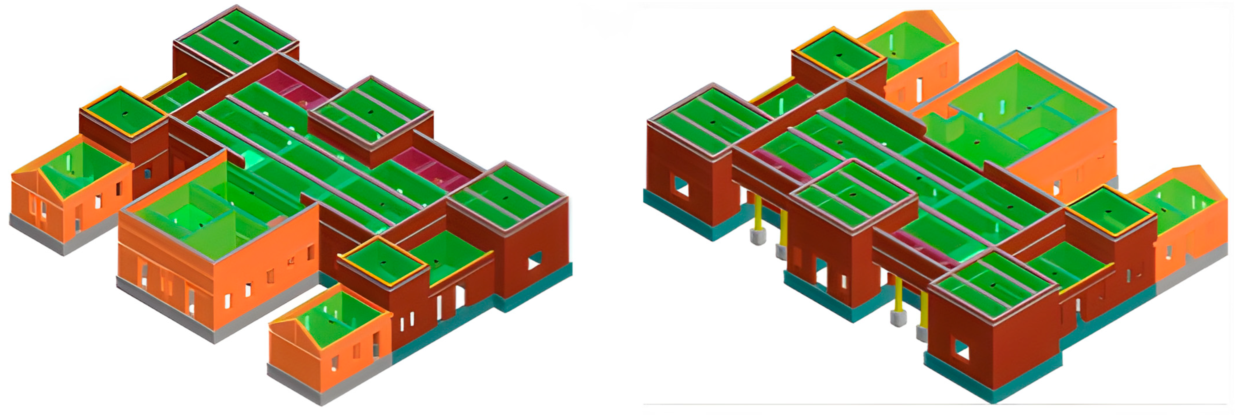
The seismic resistance of the building was analyzed using the 3Muri software, which implements the equivalent frame method for nonlinear static (pushover) analysis of masonry structures [12,25,26]. The computational model (Figure 4 and Figure 5) was assembled based on detailed architectural plans, ensuring accurate representation of wall geometries, openings, and construction phases. Structural elements were discretized into piers and spandrels connected by rigid nodes, while diaphragms were assumed to act as rigid horizontal planes. Material properties were assigned based on the in situ and laboratory tests summarized in Table 1, with adjustments made for walls strengthened by FRCM plasters (+50% for double-sided and +25% for single-sided applications) following established experimental findings [5,14]. Nonlinear hinges were assigned to both piers and spandrels, allowing simulation of shear and flexural failures as well as stiffness degradation beyond yielding. Boundary conditions considered the well-consolidated soil (classified as Eurocode 8 Soil Type A) without significant soil–structure interaction effects. The pushover analyses were performed for two orthogonal directions (X and Y), incrementally applying lateral forces until global or local collapse mechanisms were reached. The capacity curves obtained from these analyses were then used to determine the Ultimate Limit State (ULS) scaling factors and assess compliance with Eurocode 8 and Croatian national regulations.
The model (Figure 4 and Figure 5) is assembled using plans that accurately indicate the geometry of the building structure. It is essential to know the composition of the inter-floor structures and the properties of the foundation and roofing. The credibility of the analysis results depends on the proper consideration of the properties of the materials installed, which requires field and laboratory tests of their mechanical properties. Limited destructive methods are often used in the field, and destructive methods of material testing are used in the laboratory.
Figure 5. Computational model: northwestern and southeastern corner views; phases of construction presented following the color coding (Table 2).
Buildings 15 03334 g005
Table 2. Color coding of building model materials (see Figure 5).
MaterialColorMaterialColor
Masonry 1886 Stone pillars
Masonry 1930 Timber
Masonry 2022 Concrete
Stone foundation Steel

3.3. Results of Seismic Resistance Analysis

One of the purposes of this article is to show the impact of reinforced plasters that are transversely anchored to brick walls, thus contributing to an increase in their shear and bending resistance. Over the past fifteen years, a series of researchers have studied the effect of reinforced plaster through laboratory and field research, and based on these studies, formulated calculation bases for predicting the behavior of masonry structures during earthquakes. Due to the thinness of reinforced plaster in relation to the thickness of the walls, they cannot contribute to increasing the rigidity of the plastered wall but can increase its bending and, above all, shear strength. In the 3Muri program, the impact of reinforcement with reinforced plaster is considered as a 50% increase in the material characteristics of the coated masonry. With half lining of the wall, such as the façade walls of cultural monuments with a protected façade structure, in the case of good anchoring of the reinforcement, it is reasonable to consider a 25% increase in the mechanical characteristics of the masonry in the calculation.
To compare the effect of different degrees of strengthening, we analyzed the seismic response of the building under consideration in four different stages of consolidation of the masonry structure:
A.
Masonry structure in post-earthquake state with damaged brick walls (existing)
B.
Masonry structure, repaired by crack injection and reinforced by the construction of new masonry walls and reinforced concrete walls (design state, Figure 3)
C.
Masonry structure in the design state, with plastering part of the inner walls with double-sided reinforced plasters (design state with partial plastering, Figure 3)
D.
Masonry structure in the design state with double-sided plastering of internal walls and one-sided plastering of façade walls with reinforced plasters (design state with systematic plastering).
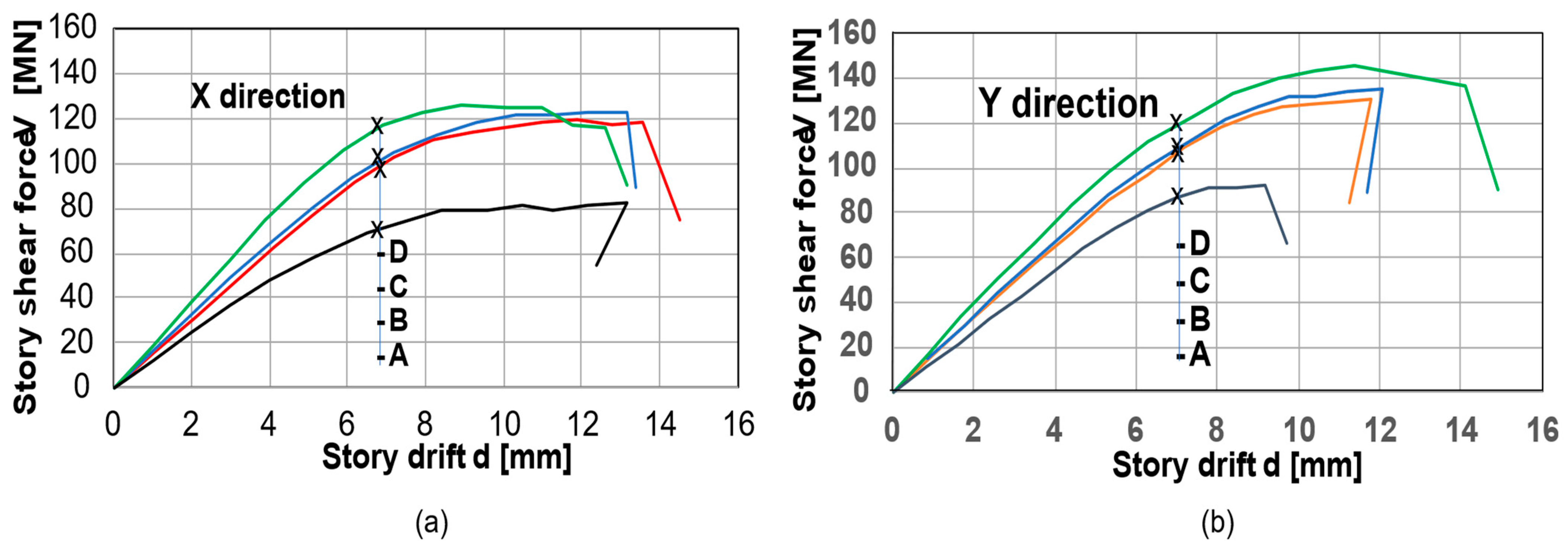
Figure 6 compares the building’s response to earthquake loads in two orthogonal directions (X and Y) using “story shear force–story drift” diagrams for all four states mentioned above. A comparison of curves B and C reveals that limited reinforcement of the walls with reinforced plasters does not significantly improve performance. However, the systematic plastering of all walls (comparison of curves B and D) notably increases the stories’ load capacity in both directions and enhances their ductility in the Y-direction.
As shown in the comparison of diagrams in Figure 6, in the south–north (Y) direction, the structure exhibits slightly higher strength but experiences earlier failures in some cases. In the east–west (X) direction, the structure demonstrates higher ductility and smoother degradation. Some of the presented structural configurations are more brittle in the Y-direction, as indicated by sudden drops. Retrofit strategies (green, blue, and red curves) improve performance in both directions but are more effective in increasing shear capacity rather than displacement capacity. Table 3 illustrates the differences in structural response numerically by comparing the values of peak story shear force (Vmax) for each curve, story drift at peak shear force (dmax), and failure story drift (dfailure), where shear force starts to degrade significantly. The figures in Table 3 clearly demonstrate the efficiency of different strengthening strategies as described in the explanation of different stages of consolidation above.
The structural response of the building is further detailed through the parameters presented in Table 4. It compiles the calculated values of the Ultimate Limit State (ULS) scaling factor α for each direction of earthquake action.
The values shown are based on the results of 12 analyses in each direction. The relevant (lowest) values of the calculated ULS factor for each direction are displayed. A comparison of the factors reveals that basic strengthening (Case B) results in a 44% increase in seismic resistance in the X-direction and a 61% increase in the Y-direction. The systematic mesh-reinforced plastering of walls (Case D) contributes an additional 12% increase in seismic resistance in the X-direction and a 30% increase in the Y-direction. However, partial plastering of walls (Case C) does not significantly affect seismic resistance compared to the measures implemented in Case B.
Fiber mesh plastering is a newer, non-traditional method for strengthening masonry walls, and therefore, there are uncertainties regarding the long-term performance of reinforced plasters under repeated seismic events. The specific long-term behavior of reinforced plasters in such conditions is not well-documented, highlighting the need for further research to validate their application in structural conservation. This gap is currently being addressed by the RILEM Technical Committee 290-IMC: Durability of Inorganic Matrix Composites Used for Strengthening of Masonry Constructions [27].
However, in our case, strengthening with reinforced plasters is not the primary measure. Even if the long-term efficiency of the plasters becomes an issue, it would not significantly affect the overall seismic behavior of the strengthened structure. The seismic resistance will remain within the limits prescribed by current Croatian Technical Regulations [23].
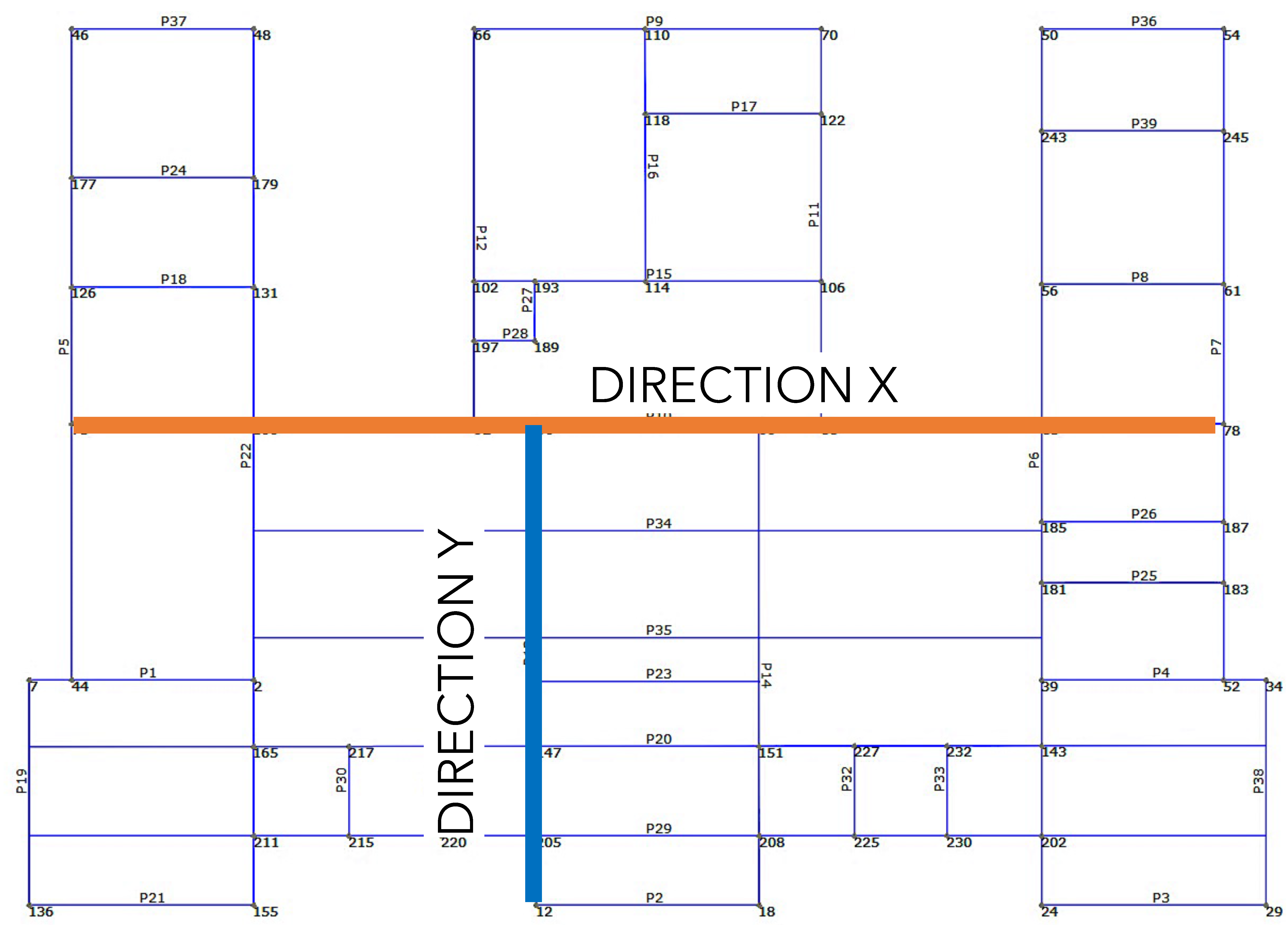
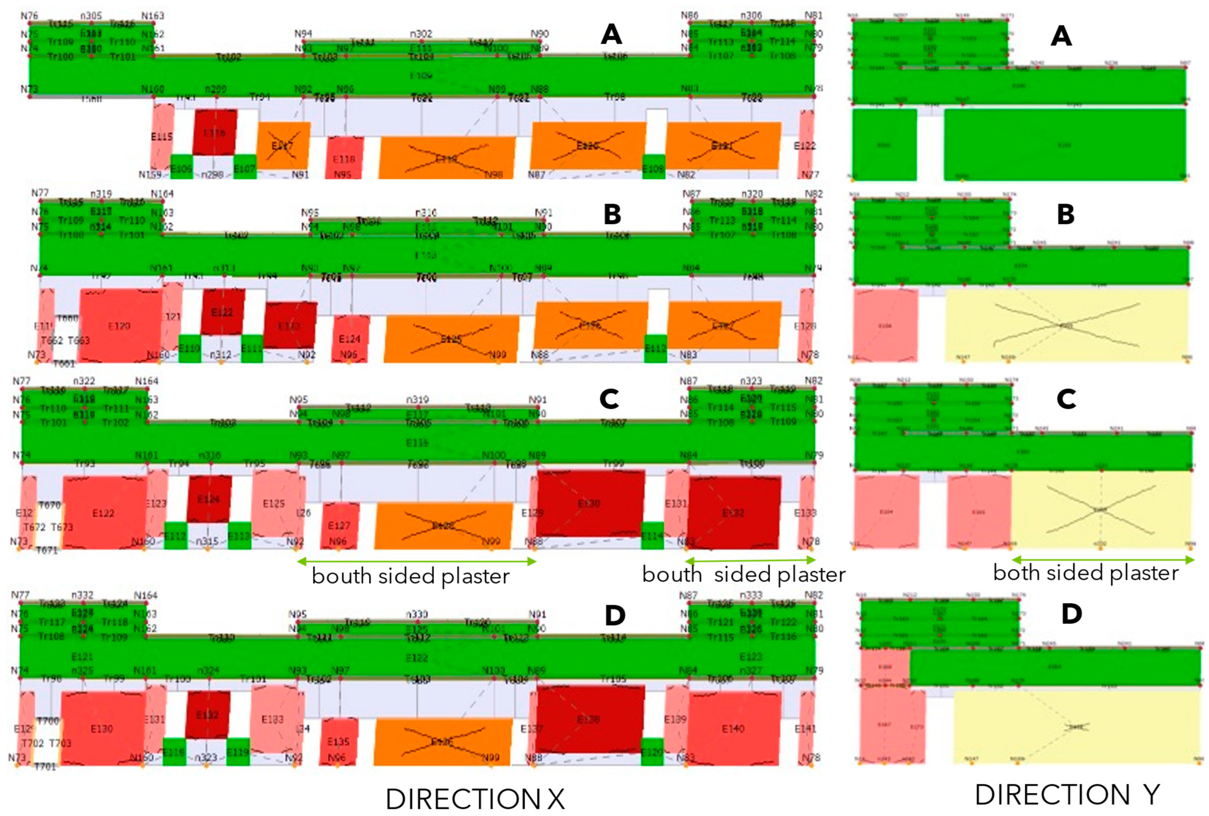
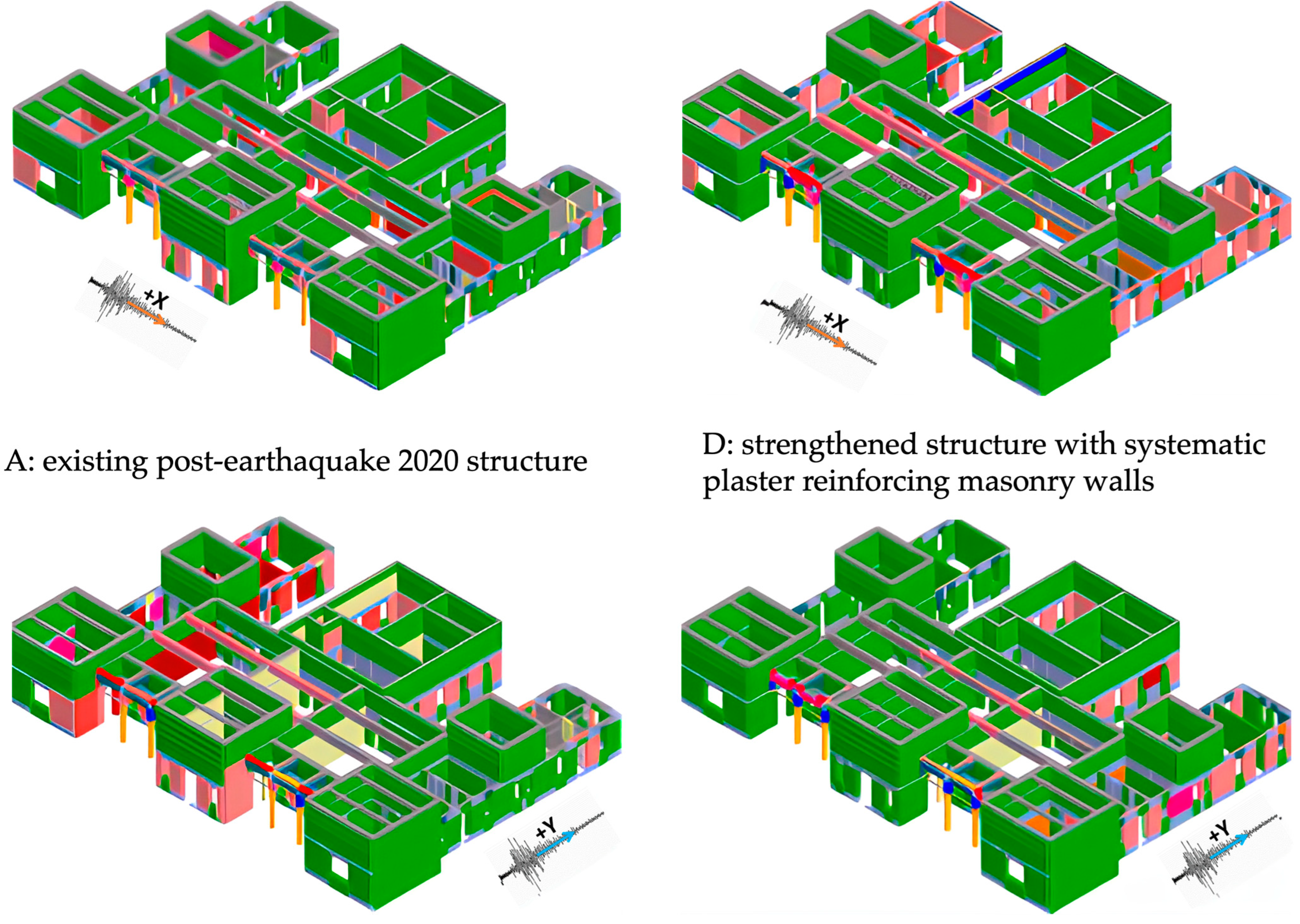
The 3Muri program identifies critical elements and evaluates the risk of global collapse due to damage or collapse of its individual parts. Different performance or damage states during a pushover analysis of wall elements are color-coded. Figure 7 presents the color legend of the types of damage to the structure’s load-bearing elements. Figure 8 presents the location of wall damages presented in Figure 9.
When comparing the wall conditions in Figure 9 and Figure 10, it is important to note that these conditions are observed at the maximum story drift due to maximum story shear force, as presented in Figure 6 above. The cases of strengthening C and B are easier to compare due to the approximately equal values of story drift and shear force. In the X-direction, the impact of the change in the wall response is visible only in the wall on the far east side, where plastering increased its shear strength to such an extent that it failed due to bending. This is because reinforced plaster increases the shear strength more than the bending strength of the wall. The other walls in the X-direction did not change the response mechanism, as in both cases, they experienced the same type of shear damage (initiation of shear failure).
In the Y-direction, the response mechanism of the walls changed, starting from the plastered wall to the south. The non-plastered walls failed due to bending, while the plastered walls only experienced initial shear damage. The systematic plastering of walls (Case D) increased the seismic resistance of the building (Figure 6, Table 4). The magnitude and type of damage after reaching maximum story drift and maximum story shear force were more favorable than in the other three cases, as seen in both Figure 9 and Figure 10.
Figure 10 illustrates the extent of structural damages for two extreme cases: Case A, representing the post-earthquake condition of the structure, and Case D, representing the strengthened structure. In Case D, new masonry and concrete walls were added, and existing masonry walls were systematically strengthened with fiber mesh-reinforced renders (as shown in Figure 3).
In the depicted response of model Case A (original, earthquake-damaged structure), a significant presence of orange and red elements is visible. These indicate that many masonry piers and spandrels are reaching or exceeding their capacity under seismic action. The structure does not meet life-safety performance objectives, especially under design-level earthquakes. Global instability might occur if collapse mechanisms appear in both piers and horizontal elements (spandrels).
The response of model Case D (ultimately strengthened structure) shows that the combined traditional strengthening with the reinforcement of masonry walls through systematic FRCM plastering delays and reduces the extent of damage. Most of the walls remain in green or yellow states, even at high drift levels. The number of red zones is reduced or absent, indicating a shift of the failure mechanism toward higher performance. This implies improved ductility and energy dissipation capacity, with better redistribution of seismic forces. The model meets “damage limitation” or even “life safety” performance targets, depending on the input spectrum and capacity curves.
The story drift of the structure in the X-direction (Figure 6a) was almost equal in both cases A and D. However, the structure in Case D sustained 52% higher story shear force than that in Case A. In the Y-direction, the strengthened structure (Case D) achieved 54% higher story drift and 57% higher shear resistance (Figure 6b), demonstrating the significant increase in structural ductility and strength due to the strengthening measures. Despite the higher story shear force, the structure in Case D sustained less damage compared to Case A, clearly justifying the successful design of the repair and strengthening measures.

4. Discussion

The findings clearly support the use of systematic FRCM plastering in combination with targeted wall reconstruction as a viable strategy for seismic retrofitting of heritage masonry buildings. The analysis confirms that global rather than localized reinforcement is required to effectively improve performance across the structure, particularly in irregular and asymmetrical buildings like the Mirogoj mortuary.
The adoption of Case D produced the most favorable results, raising both ductility and shear capacity to exceed Eurocode and national standards. Interestingly, the partial strengthening in Case C offered only marginal improvements, and in some walls, even failed to change the failure mode, confirming that partial interventions may leave weak links unaddressed.
The role of detailed damage mapping provided by 3Muri is crucial in visualizing how reinforcement modifies failure mechanisms. The identification of early shear or bending failures highlights critical areas for future intervention design. Despite the promising performance of FRCM, its durability under environmental cycling and repeated seismic loading remains insufficiently understood. Standards like those developed by RILEM TC 290-IMC must inform further practical and regulatory developments.

5. Conclusions

The seismic strengthening of the Mirogoj mortuary via a hybrid strategy—integrating new masonry and reinforced concrete walls with systematic FRCM plastering—successfully elevates the structure from a post-earthquake vulnerable state to one that exceeds Level 4 seismic safety requirements under Croatian and Eurocode 8 criteria. The study quantifies the contribution of each component: the insertion of new rigid walls provides a foundational 44–61% gain in lateral resistance, while comprehensive FRCM reinforcement delivers an additional 12–30% improvement, shifting failure mechanisms away from brittle shear toward more ductile, energy-dissipating behavior. The retrofit reduces damage concentration, increases global robustness, and significantly improves structural reparability after future seismic events.
Partial strengthening (Case C) is insufficient; it leaves critical weak links and fails to change underlying failure modes, underscoring that effective heritage seismic retrofit must be holistic rather than piecemeal. The approach balances structural efficacy with conservation ethics—being minimally invasive, reversible, and compatible with the historic fabric—thereby offering a practical template for similar heritage masonry buildings where both authenticity and safety are priorities.
Following the results of the analysis based on the modeling with the 3Muri software, the following recommendations can be considered in similar cases:
  • Adoption Pathway: The demonstrated methodology can be transferred to other irregular, asymmetrical historic masonry structures, provided it is preceded by in situ and laboratory characterization to tailor interventions.
  • Design Guidance: Retrofit design should prioritize global FRCM application over localized patching to avoid residual vulnerabilities.
  • Long-Term Validation: Targeted research and field monitoring should address remaining uncertainties in FRCM behavior under repeated seismic loading, environmental degradation, and out-of-plane demands—potentially through instrumented post-retrofit performance tracking.
  • Policy Integration: Heritage seismic programs should incorporate this evidence-based hybrid framework into guidelines for Level 4 upgrades, incentivizing comprehensive rather than incremental retrofits.
  • In sum, this study offers a robust, reproducible, and culturally sensitive seismic strengthening strategy that bridges historical preservation with contemporary safety imperatives.

Author Contributions

Conceptualization, R.Ž.; methodology, R.Ž.; software, R.Ž.; writing—original draft preparation, R.Ž. and B.V.; writing—review and editing, R.Ž. and B.V.; visualization, R.Ž. All authors have read and agreed to the published version of the manuscript.

Funding

This research received no external funding.

Data Availability Statement

The original contributions presented in this study are included in the article. Further inquiries can be directed to the corresponding author.

Acknowledgments

As part of the post-earthquake renovation of damaged buildings in Zagreb, the cemetery manager, Zagrebački holding, d. o. o., Zagreb, commissioned the preparation of a renovation project that includes the rehabilitation and seismic reinforcement of the structure. The design office Planetaris, d. o. o., Zagreb, completed the renovation project, and the assessment presented in this article is part of that project.

Conflicts of Interest

The authors declare no conflict of interest.

Correction Statement

This article has been republished with a minor correction to the Data Availability Statement. This change does not affect the scientific content of the article.

References

  1. Papayianni, I. Retrofitting and strengthening masonries of heritage structures: Materials used. In Encyclopedia of Earthquake Engineering; Beer, M., Kougioumtzoglou, I.A., Patelli, E., Au, S.-K., Eds.; Springer: Berlin/Heidelberg, Germany, 2014; pp. 2272–2286. [Google Scholar] [CrossRef]
  2. Keshmiry, A.; Hassani, S.; Dackermann, U.; Li, J. Assessment, repair, and retrofitting of masonry structures: A comprehensive review. Constr. Build. Mater. 2024, 442, 137380. [Google Scholar] [CrossRef]
  3. Padalu, P.; Vashisht, R.; Ramancharla, P.A. Review on Construction Techniques and Structural Restoration of Ancient Masonry Buildings. In Recent Developments in Structural Engineering; Kumar, R., Gadve, S.S., Eds.; Springer: Singapore, 2024; Volume 1, pp. 335–350. [Google Scholar] [CrossRef]
  4. Majumder, A.; Stochino, F.; Fraternali, F.; Martinelli, E. Seismic and thermal retrofitting of masonry buildings with fiber reinforced composite systems: A state-of-the-art review. Int. J. Struct. Glass Adv. Mater. Res. 2021, 5, 41–67. [Google Scholar] [CrossRef]
  5. Jarc Simonič, M.; Gostič, S.; Bosiljkov, V.; Žarnić, R. In-situ and laboratory tests of old brick masonry strengthened with FRP in innovative configurations and design considerations. Bull. Earthq. Eng. 2015, 13, 257–278. [Google Scholar] [CrossRef]
  6. Corradi, M.; Mustafaraj, E.; Speranzini, E. Sustainability considerations in remediation, retrofit, and seismic upgrading of historic masonry structures. Environ. Sci. Pollut. Res. 2023, 30, 25274–25286. [Google Scholar] [CrossRef] [PubMed]
  7. Žarnić, R.; Vodopivec, B. Inclusive Approach to Cultural Heritage Resilience. In Handbook of Cultural Heritage Analysis; D’Amico, S., Venuti, V., Eds.; Springer: Cham, Switzerland, 2022; pp. 2037–2072. [Google Scholar] [CrossRef]
  8. De Vita, M.; Mannella, A.; Sabino, A.; Marchetti, A. Seismic Retrofit Measures for Masonry Walls of Historical Buildings, from an Energy Saving Perspective. Sustainability 2018, 10, 984. [Google Scholar] [CrossRef]
  9. Kaya, D.I.; Pintossi, N.; Koot, C.A. Adaptive Reuse of Cultural Heritage: Barrier Assessment and Policy-Related Recommendations. In Adaptive Reuse of Cultural Heritage: Circular Business, Financial and Governance Models; Girard, L.F., Gravagnuolo, A., Eds.; Springer Nature: Berlin/Heidelberg, Germany, 2025; pp. 379–407. [Google Scholar] [CrossRef]
  10. Babatunde, S.A. Review of strengthening techniques for masonry using fiber reinforced polymers. Compos. Struct. 2017, 161, 246–255. [Google Scholar] [CrossRef]
  11. Triantafillou, T.C.; Fardis, M.N. Strengthening of historic masonry structures with fiber reinforced plastic composites. WIT Trans. Built Environ. 2025, 15, 129–136. Available online: https://www.witpress.com/Secure/elibrary/papers/STR95/STR95016FU2.pdf (accessed on 12 July 2025).
  12. 3Muri Project—STADATA. Available online: https://stadata.com/3-muri-project/ (accessed on 4 August 2025).
  13. Cannizzaro, F.; Pantò, B.; Lepidi, M.; Caddemi, S.; Caliò, I. Multi-Directional Seismic Assessment of Historical Masonry Buildings by Means of Macro-Element Modelling: Application to a Building Damaged during the L’Aquila Earthquake (Italy). Buildings 2017, 7, 106. [Google Scholar] [CrossRef]
  14. Athmani, A.; Grairia, S.; Seboui, H.; Khemis, A.; Formisano AAdemovic, N. Integrated seismic vulnerability assessment for heritage educational buildings in Annaba city: Combining probabilistic hazard analysis and structural modeling. Multidiscip. Model. Mater. Struct. 2024, 20, 1256–1283. [Google Scholar] [CrossRef]
  15. Salaman, A.; Stepinac, M.; Matorić, I.; Klasić, M. Post-earthquake condition assessment and seismic upgrading strategies for a heritage-protected school in Petrinja, Croatia. Buildings 2022, 12, 2263. [Google Scholar] [CrossRef]
  16. Gonçalves, M.; Ponte, M.; Bento, R. Seismic Assessment of Existing Masonry Buildings Using Damage Mechanics. Buildings 2024, 14, 2395. [Google Scholar] [CrossRef]
  17. Longobardi, G.; Moşoarca, M.; Gruin, A.; Ion, A.; Formisano, A. An Innovative, Lightweight, and Sustainable Solution for the Inte-grated Seismic Energy Retrofit of Existing Masonry Structures. Sustainability 2024, 16, 4791. [Google Scholar] [CrossRef]
  18. Estêvão, J.; Tomás, B.; Laranja, R.; Braga, A. Seismic Retrofitting of an Existing Masonry School Building: A Case Study in Algarve. In Sustainability and Automation in Smart Constructions; Rodrigues, H., Gaspar, F., Fernandes, P., Mateus, A., Eds.; Advances in Science, Technology & Innovation; Springer: Cham, Switzerland, 2021; pp. 349–355. [Google Scholar] [CrossRef]
  19. Formisano, A.; Ademovic, N. An overview on seismic analysis of masonry building aggregates. Front. Built Environ. 2022, 8, 966281. [Google Scholar] [CrossRef]
  20. Damjanović, D.; Premužić Ančić, M.; Suljić, A. Mortuary of the Mirogoj Cemetery in Zagreb. Rad. Instituta Za Povij. Umjet. 2022, 46, 109–128. [Google Scholar] [CrossRef]
  21. Act on Reconstruction of Earthquake-Damaged Buildings in the City of Zagreb, Krapina-Zagorje County, Zagreb County, Sisak-Moslavina County and Karlovac County (Official Gazette 102/20, 10/21, 117/21). Available online: https://www.zakon.hr/z/2656/zakon-o-obnovi-zgrada-ostecenih-potresom-na-podrucju-grada-zagreba%2C-krapinsko-zagorske-zupanije%2C-zagrebacke-zupanije%2C-sisacko-moslavacke-zupanije-i-karlovacke-zupanije (accessed on 9 September 2025).
  22. Technical Regulation on Building Structures (Official Gazette 17/17, 75/20, 7/22). Available online: https://www.zakon.hr/c/podzakonski-propis/45058/nn-75-2020-%281.7.2020.%29%2C-tehnicki-propis-o-izmjeni-i-dopunama-tehnickog-propisa-za-gradevinske-konstrukcije (accessed on 9 September 2025).
  23. Eurocode 8 (HRN EN 1998-1:2011; HRN IN 1998-3/NA). Available online: https://repozitorij.hzn.hr/norm/HRN+EN+1998-1%3A2011 (accessed on 9 September 2025).
  24. Turnšek, V.; Čačovič, F. Some experimental results on the strength of brick masonry walls. In Proceedings of the 2nd International Brick Masonry Conference, Stok-on-Trent, UK, 12–15 April 1971; West, H.W.H., Ed.; British Ceramic Research Association: Stoke-on-Trent, UK, 1971; pp. 149–156. [Google Scholar]
  25. Penna, A.; Lagomarsino, S.; Galasco, A. A nonlinear macro-element model for the seismic analysis of masonry buildings. Earthq. Eng. Struct. Dyn. 2014, 43, 159–179. [Google Scholar] [CrossRef]
  26. Marques, R.; Lourenço, P.B. Unreinforced and confined masonry buildings in seismic regions: Validation of macro-element models and cost analysis. Eng. Struct. 2014, 64, 52–67. [Google Scholar] [CrossRef]
  27. RILEM Technical Committee 290-IMC: Durability of Inorganic Matrix Composites used for Strengthening of Masonry Constructions. Available online: https://www.rilem.net/groupe/290-imc-durability-of-inorganic-matrix-composites-used-for-strengthening-of-masonry-constructions-384 (accessed on 7 July 2025).
Figure 1. View of the Mirogoj mortuary in the early 20th century and seismic hazard map of Croatia showing the 2020 Zagreb earthquake epicenter with a 475-year return period (b).
Buildings 15 03334 g001
Figure 2. Plan of the Mirogoj mortuary presenting the phases of its construction.
Buildings 15 03334 g002
Figure 3. Ground floor plan with added masonry and reinforced concrete walls, and rendering of both sides with fiber-mesh reinforced plasters (stage of consolidation, Case C).
Buildings 15 03334 g003
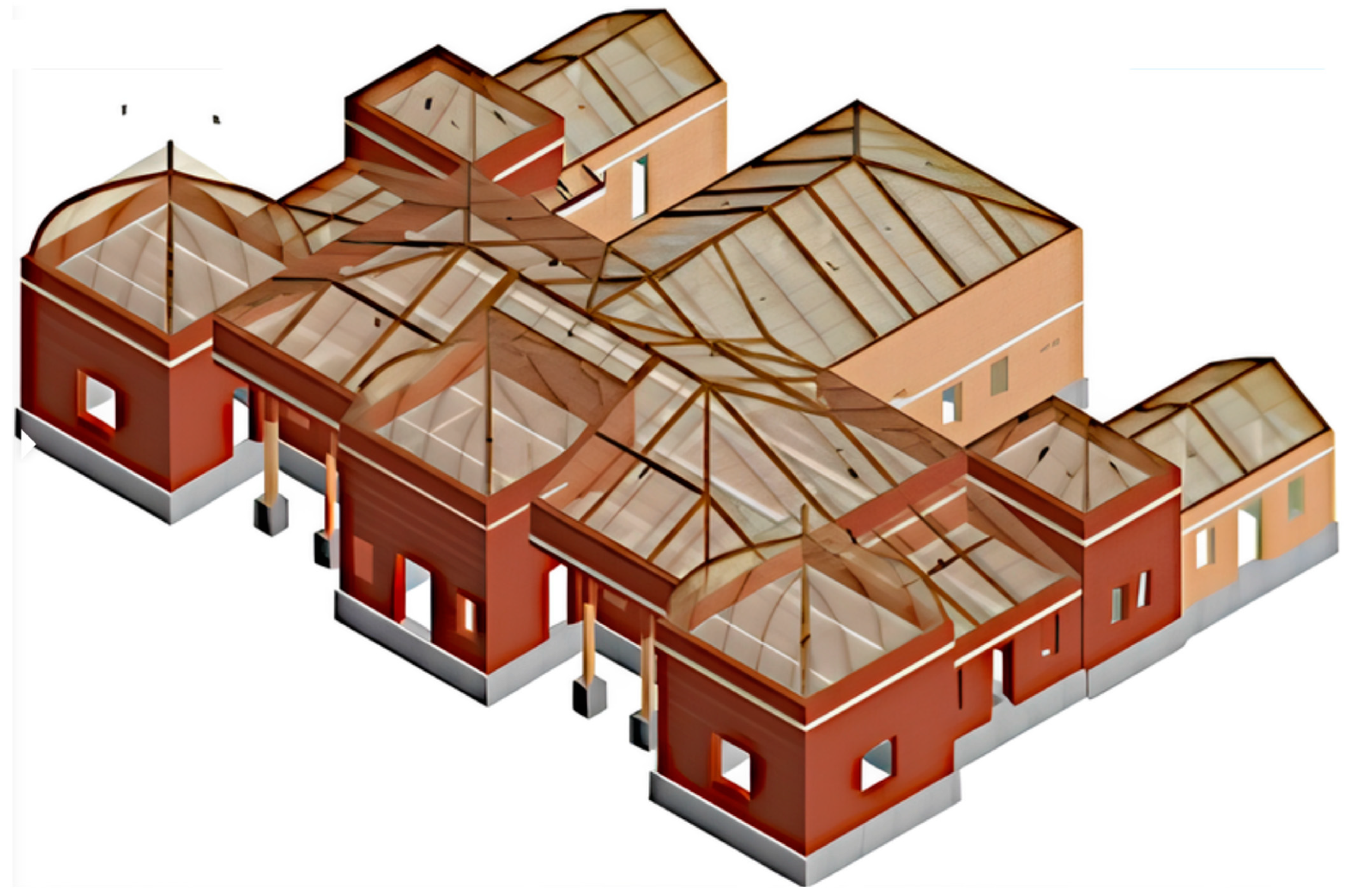
Figure 4. Mortuary building model as created with the 3Muri software.
Buildings 15 03334 g004
Figure 6. Comparison of floor diagrams of the building’s seismic response for all four stages of consolidation: earthquake action in X-direction (a) and in Y-direction (b).
Buildings 15 03334 g006
Figure 7. Colors legend that identifies the type of damage of structural elements (masonry walls and reinforced concrete elements) in Figure 9 and Figure 10.
Buildings 15 03334 g007
Figure 8. The wall rows in the building layout, which are presented in Figure 9.
Buildings 15 03334 g008
Figure 9. Damages to structural elements across two wall rows for different cases (A to D).
Buildings 15 03334 g009
Figure 10. Comparison of wall damage in the entire building: Case A vs. Case D.
Buildings 15 03334 g010
Table 1. Mechanical properties of masonry.
ParameterMasonry
1886
Masonry
1886
Masonry
1886
Stone PillarsStone Found
Modulus of elasticity E [N/mm2]900700210010802580
Shear modulus G [N/mm2]300230700180430
Specific weight [kN/m3]1818182222
Average compressive strength
fm [N/cm2]
20015023085350
Shear strength (Turnšek-Čačovič [24])
τ [N/cm2]
15801352.98.8
Characteristic compressive strength
fk [N/cm2]
1001212040170
Confidence factor CF1.351.351.351.351.35
Material security factor γm33333
Shear drift0.00530.00530.00530.00530.0053
Bending drift0.01070.01070.01070.01070.0107
ϕ ∞00000
Table 3. Comparison of structural response on earthquake action in X-direction and in Y-direction.
Configuration caseVmax-X [MN]dmax-X [mm]dfailure-X [mm]Vmax-Y [MN]dmax-Y [mm]dfailure-Y [mm]
D12510.5141309.513.5
C12011.01312510.012.5
B11010.0121159.811.5
A808.011857.510.0
Table 4. Calculated Ultimate Limit State (ULS) scaling factor α.
Analyzed Configurations of StructureαULS
Soil Type A (S = 1),
Importance Factor I = 1,
Behavior Factor q = 1.5
Direction XDirection Y
Existing post-earthquake 2020 structure (Case A)0.640.56
Strengthened structure (Case B)0.920.90
Strengthened structure with additional
reinforced plasters on individual walls (Case C)
0.930.94
Strengthened structure with systematic
plaster-reinforcing of masonry walls (Case D)
1.031.17
Disclaimer/Publisher’s Note: The statements, opinions and data contained in all publications are solely those of the individual author(s) and contributor(s) and not of MDPI and/or the editor(s). MDPI and/or the editor(s) disclaim responsibility for any injury to people or property resulting from any ideas, methods, instructions or products referred to in the content.