1. Introduction
Physical modelling is an essential tool that accurately captures structural responses under various loading conditions, enabling visualization of deformation and damage propagation in laboratory-scale specimens [
1]. By employing scaled-down models, engineers can experimentally evaluate the behavior of full-scale structures without incurring the significant costs and efforts associated with full-scale testing [
2]. Such models provide critical qualitative and quantitative data contributing to safety evaluations and identifying potential vulnerabilities and failure mechanisms [
3]. Additionally, scaled-down models allow practicing engineers to efficiently examine numerous design scenarios, making these models highly valuable for diverse civil engineering applications.
Engineering design codes increasingly recognize the value of data obtained from scaled-down model tests. For example, the 2023 New York City Building Code permits such model test data to ascertain stress magnitudes, directions, and load distributions [
4]. Similarly, the American Concrete Institute (ACI) code ACI 318 endorses experimental analysis methods when they provide safe design bases, specifically encouraging the use of micro-concrete models for complex shell structures (Commentary R19.2.4) [
5]. The 2020 National Building Code of Canada also acknowledges the role of scaled-down models in design, although it lacks detailed procedural guidelines [
6].
Engineers have long utilized physical modelling techniques across various domains. Historically, in 1962, the Research Directorate of the United States Air Force Special Weapons Center employed physical modelling to examine dynamically loaded buried concrete structures, which led to the establishment of scaling laws correlating model structures and soils to their prototypes [
7]. Recognizing the impracticality and high costs associated with full-scale explosive testing, subsequent research shifted toward developing reduced-scale models guided by Froude similitude principles, significantly reducing testing costs [
8]. This research highlighted that scaled-down model materials typically exhibit weaker behavior than prototypes under gravitational conditions (1-g soil–structure interaction), requiring adjustments to concrete mixes. Nonetheless, accurately replicating concrete’s nonlinear, inelastic behavior remained challenging, often resulting in geometrically scaled but overly stiff models [
9].
Accurate physical models of RC structures must capture the complete structural response from the elastic range through yielding and failure [
10]. Both material and geometric nonlinearities must be represented to achieve accurate elastic and inelastic behavior modelling, mandating strict adherence to geometric similitude [
11]. This adherence closely matches model materials’ stress–strain relationships and failure strains with those of their prototypes [
12].
Material scaling laws support models in fulfilling equilibrium and compatibility conditions, thereby simplifying the achievement of accurate physical representation when material similitude is thoroughly established through extensive preliminary testing [
13]. However, when constraints limit compliance with all similitude criteria, models become distorted, necessitating interpretation to relate model outcomes to prototype behaviors [
14]. Significant distortion undermines confidence in prototype predictions, underscoring the critical importance of thorough adherence to material scaling laws, which researchers often treat as optional, thereby reducing the reliability of scaled models [
15,
16,
17].
Due to a lack of clear guidance in developing concrete mixes suitable for scaled-down physical modelling, this study proposes a novel low-stiffness, fine-grained concrete material created specifically to satisfy stringent Froude similitude criteria. Unlike previously developed models, this material meets the complex scaling requirements previously considered impractical for concrete [
8,
9,
13]. Adhering closely to these criteria, the proposed concrete mix enables accurate structural behavior predictions across diverse loadings, including seismic and static scenarios. A proof-of-concept test validates the developed material’s efficacy in replicating full-scale RC structural behavior, thus establishing a robust methodological foundation for future scaled-model experimentation. This development equips engineers with a reliable, cost-effective alternative to traditional full-scale structural testing.
2. Research Significance
Existing literature predominantly utilizes conventional replica scaling methods for small-scale concrete modelling. However, such methods typically fail to adequately replicate the strength and stiffness characteristics of the prototype, leading to significant distortions. Consequently, these distortions necessitate artificial gravity conditions, such as centrifuge modelling, to correct for gravitational discrepancies. This study addresses these limitations by introducing a novel concrete simulant material specifically formulated to satisfy the stringent requirements of Froude similitude. The proposed simulant achieves accurate scaling of tensile strength. It maintains critical strain parameters at compressive failure, thus adhering closely to challenging material similitude constraints traditionally considered impractical in concrete modelling.
A comprehensive experimental investigation is undertaken to evaluate the mechanical properties and confirm the compliance of the developed simulant material with Froude similitude laws. Comparative experimental tests on scaled-down reinforced concrete beams demonstrate that this innovative concrete mix accurately emulates the structural behavior observed in corresponding full-scale prototypes without resorting to artificially induced gravity environments. The results verify the feasibility and effectiveness of applying Froude similitude principles to structural concrete modelling.
This research provides a significant advancement for scaled structural modelling, laying a robust methodological framework for future studies. It offers researchers and practicing engineers a reliable tool for accurately predicting structural responses while substantially reducing the associated experimental costs and resources.
Physical modelling represents a promising technique for addressing the rehabilitation challenges faced by many existing structures, particularly in densely populated urban areas. In such contexts, increased demand, vertical expansion, or changes in building use often impose additional loading conditions [
18]. As a result, there is a growing need to enhance the capacity of existing RC structures, either by restoring their original strength or by increasing it through strengthening interventions, which could be accurately designed and assessed via the modelling technique proposed in this study.
3. Background
Scaling laws form the fundamental basis for the physical modelling of structures, ensuring accurate similitude between full-scale prototypes and their corresponding scaled-down models. This section discusses the theoretical principles underlying scaling laws, provides an overview of modelling techniques in the literature, and outlines the scaling methodology adopted in this study.
3.1. Dimensional Analysis
The initial phase in designing a scaled physical model involves identifying the primary variables influencing the structural response. Often, numerous physical variables affect structural behavior; however, these can typically be described using fundamental units—mass (M), length (L), and time (T). Buckingham’s theorem [
19], established in 1914, provides a systematic approach to dimensional analysis. According to this theorem, any dimensionally homogeneous equation involving multiple physical variables can be reduced to an equivalent equation composed of dimensionless parameters. A physical relationship involving
variables, as expressed in Equation (1), can thus be represented by dimensionless products as shown in Equation (2):
Here,
represents dimensionless parameters formed from the original variables
and
denotes the number of fundamental dimensions.
Table 1 lists the physical quantities commonly involved in structural modelling and their corresponding dimensions. Establishing dimensional similarity between models and prototypes allows engineers to accurately simulate structural behaviors at reduced scales.
3.2. Scaling Methods
For accurate simulation, all dimensionless parameters must remain identical between the prototype and its scaled-down model. Consequently, the scale factor for any given quantity (
) is defined as the ratio of the prototype value (
) to the model value (
), as described by Equation (3):
An effective scaled model must satisfy geometric, kinematic, and dynamic similarity with its prototype [
20,
21,
22]. Geometric similarity ensures that all linear dimensions of the model correlate to those of the prototype by a constant length scale factor (
). Kinematic similarity requires velocities at corresponding points in the model and prototype to maintain a consistent velocity scale factor (
). Dynamic similarity dictates that corresponding forces in both prototype and model follow consistent directions and magnitudes related by a force scale factor (
). Zahrah et al. [
8] summarized the derivation of scale factors through the following steps: (1) selection of dimensionally independent base variables, (2) expression of fundamental units’ scale factors based on chosen base variables, and (3) derivation of scale factors for remaining variables.
Structural scaling typically employs two primary methodologies: replica scaling and Froude scaling. In replica scaling, the base variables are length, mass density, and stress. Replica scaling demands artificially induced gravitational conditions (e.g., centrifuge modelling) to maintain accurate scaling, as acceleration scales inversely with length (
) [
23,
24]. Without artificial gravity, replica scaling often yields distorted results and overly stiff models, especially in soil–structure interaction applications [
25,
26,
27,
28,
29].
Froude scaling, in contrast, uses length, mass density, and acceleration as base variables. Crucially, the acceleration scale factor is set to unity (
), eliminating the need for artificial gravity and making it ideal for accurately simulating gravitational effects [
9]. According to Zahrah et al. [
8], scale factors for mass, time, stress, velocity, and force in Froude scaling are derived as follows:
Rearranging Equations (5) and (6) gives:
Considering
(Froude scaling), Equation (8) is simplified to:
Thus, the stress scale factor (
) becomes:
Similarly, the velocity scale factor (
) is expressed as:
The force scale factor (
) is:
Table 2 comprehensively summarizes replica and Froude scaling factors for essential physical quantities.
3.3. Practical Applications
While previous research has demonstrated effective modelling with scale factors as small as 1:4 using standard concrete materials, further reductions (e.g., 1:8 or smaller) necessitate specialized finer-grained concrete mixes [
13]. At scale factors of 1:10 or smaller, unpredictable size effects and practical constraints arise if similitude laws are not carefully observed. Hence, this study specifically examines the applicability and accuracy of similitude laws at the challenging scale factor of 1:10, focusing on developing a practical, cost-effective, low-stiffness fine-grained concrete simulant material. The proposed simulant material aims to replicate the macroscopic mechanical properties of prototype concrete closely, fulfilling stringent Froude similitude criteria previously considered impractical for concrete [
8,
9,
13]. This study verifies the potential of scaled-down models to predict full-scale structural responses accurately through rigorous experimental validation, thus establishing robust methodologies for future concrete physical modelling endeavours.
4. Experimental Study
4.1. Prototype Specimens
A total of six cylindrical specimens measuring 100 mm in diameter by 200 mm in height and six prismatic specimens measuring 100 mm × 100 mm × 200 mm were fabricated as ordinary concrete prototypes. Cylindrical specimens were intended to achieve a compressive strength of 35 MPa, conforming to the minimum requirements for CSA A23.3 [
30] exposure class A1/C1. The water-to-cement ratio was maintained at 0.48 by weight, consistent with non-air-entrained concrete to achieve the targeted 28-day strength [
5].
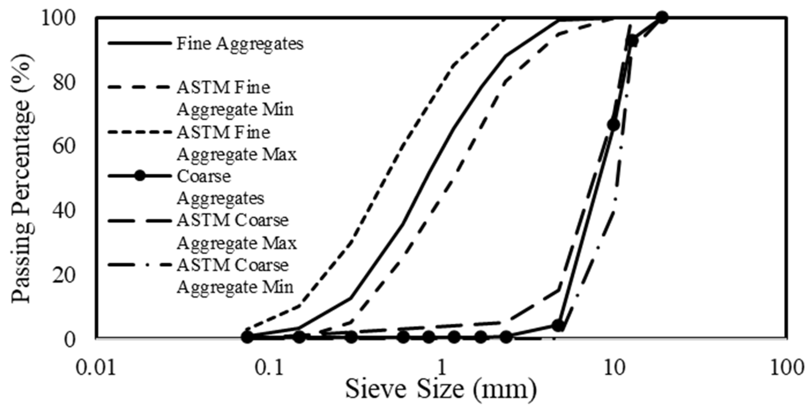
The concrete mix utilized locally sourced materials. The constituents per cubic meter were 450 kg of Portland general use (type GU) cement, 1090 kg coarse aggregates, 820 kg fine aggregates, and 245 kg water. Coarse and fine aggregates were compliant with ASTM C33 [
31] specifications. Particle-size distribution for both aggregates was determined following ASTM C136 [
32] procedures, and the results are presented in
Figure 1. Aggregate bulk densities were measured using standard Proctor methods (ASTM C29 [
33]), resulting in 1600 kg/m
3 for coarse aggregate and 1820 kg/m
3 for fine aggregate. The fine aggregate was at a saturated surface-dry condition with an average moisture content of 2.7%.
The specimens were cast and cured according to ASTM C192 [
34]. Dry constituents were thoroughly mixed before adding water, ensuring uniform consistency. Concrete was then placed into cylindrical and prismatic molds, filled in layers, and compacted using a tamping rod per standard guidelines to eliminate air pockets. After 24 h, specimens were de-molded and left to air-cure for 28 days in laboratory conditions. Before testing, cylindrical and prismatic specimens’ top and bottom faces were capped with molten sulfuric compounds to ensure uniform loading surfaces.
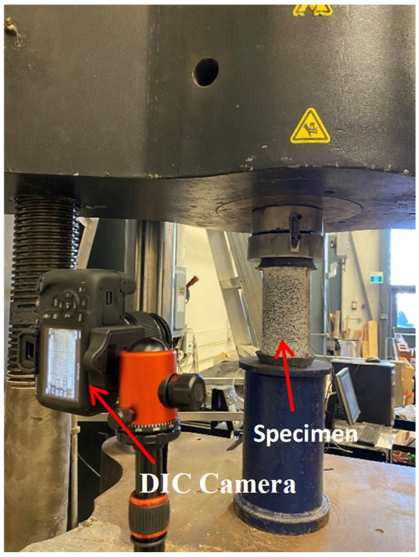
Compressive strength tests followed ASTM C39 [
35] procedures, utilizing a 2 MN Instron hydraulic testing machine at a displacement-controlled rate of 1.58 mm/min. A loading plate was placed on the specimens to minimize eccentric loading. Two linear strain gauges (120 mm length) were attached to opposite sides of each specimen to measure axial strains.
Figure 2 illustrates the compressive test setup. The same loading apparatus evaluated the split tensile strength according to ASTM C496 [
36]. Digital image correlation (DIC) also analyzed deformation patterns and strain fields. Specimen surfaces were painted white, then speckled with a uniform black pattern. A Canon Rebel T7 camera (Canon, Taiwan, China) recorded deformation, with subsequent analysis performed using GOM Correlate 2022 software [
37]. This DSLR camera had a 24.1 megapixel sensor, with a 1080p resolution (1920 × 1080 pixels) set at 30 frames per second.
4.2. Model Specimens
Six cylindrical specimens (50 mm × 100 mm) and six prismatic specimens (40 mm × 40 mm × 80 mm) were cast using a purpose-designed scaled-down concrete mix to assess the feasibility of applying similitude principles at small scales. A scale factor of 1:10 was adopted throughout the study. The target compressive strength for the scaled-down concrete was 3.5 MPa, representing 10% of the 35 MPa strength achieved in the prototype specimens. This strength reduction is consistent with the requirements of Froude similitude for 1-g physical modelling.
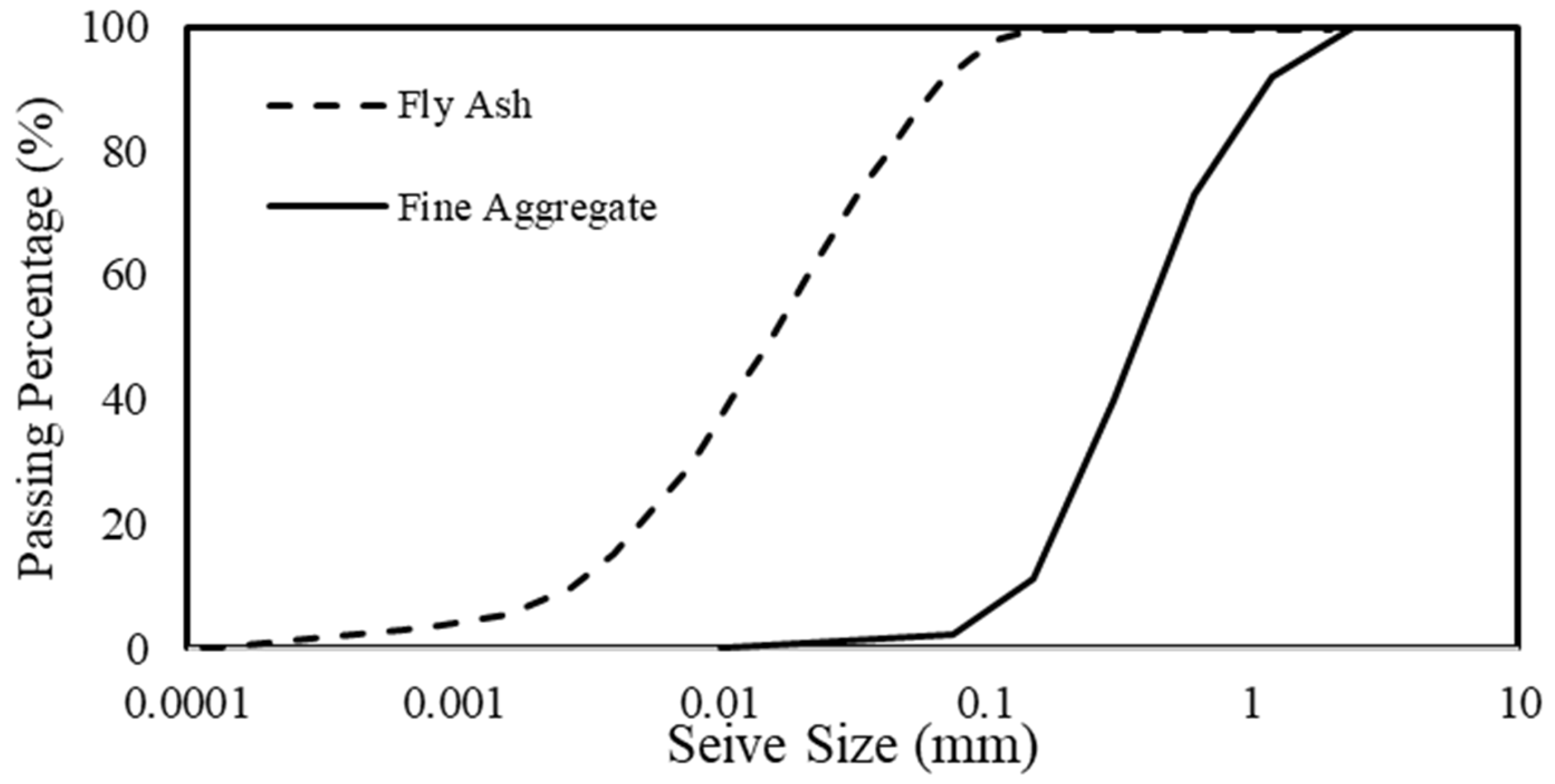
Due to the focus on mechanical behavior rather than absolute force measurements, the selected dimensions ensured geometric compatibility with the prototype specimens while maintaining manageable sizes for laboratory testing. Importantly, 92% of the aggregate size in the full-scale mix was below 13 mm; therefore, the scaled-down mix was designed such that approximately 92% of its aggregates were smaller than 1.3 mm. This scaling maintained a 1:10 similitude in aggregate size and prevented dimensional distortion, as shown by the comparison between
Figure 1 and
Figure 3.
Unlike some scaling studies that reduce individual particle sizes, this study focused on adjusting the mechanical properties of the concrete while maintaining practical, readily available materials. The scaled-down concrete was designed to replicate the macroscopic stress–strain characteristics of the full-scale prototype mix, consistent with the Froude similitude laws. Several trial batches were initially prepared to refine the workability, stiffness, and strength of the developed mix. Adjustments in water content and fly ash percentage were explored. The final mix presented in the manuscript represents the optimized iteration that best satisfied Froude similitude targets while maintaining practical workability and mechanical scaling.
The scaled-down concrete mix design comprised 213 kg of cement, 21.3 kg of Class F fly ash, 1490 kg of fine aggregate (Shaw masonry sand), and 307 kg of water per cubic meter. The scaled-down mix required aggregates with a maximum particle size of about 1.3 mm (1/10 of the maximum prototype). Using only masonry sand at this fine grading tended to increase stiffness and reduce workability. Consequently, Fly ash was introduced to the developed mix as 10% by mass of the cementitious material to enhance the mix’s workability and to fine-tune the mechanical properties to comply with the strength and stiffness requirements of Froude similitude. Enhanced workability for the developed mix was of prime importance as the study targeted small molds, where compaction is more difficult. The aggregate in the scaled-down specimens had a bulk density of 1756.8 kg/m
3 and met the fine grading requirements suitable for small-scale concrete applications. The particle size distribution for the fine aggregate and fly ash is illustrated in
Figure 3.
All dry ingredients were mixed for 10 min before water was gradually introduced to ensure proper homogeneity and repeatability. The mixing process continued until a consistent and workable mixture was obtained. The fresh mix was poured into the 40 mm × 40 mm × 80 mm prism molds per ASTM C109 [
38], ensuring minimal air entrapment. For the cylindrical molds (50 mm × 100 mm), concrete was added in thirds, each layer compacted, and the mold walls tapped to release air voids.
Due to the reduced strength of the scaled-down mix, the molds were removed after 48 h rather than the standard 24. The specimens were subsequently cured in the air under laboratory conditions for 7 days to simulate practical time constraints encountered in site or laboratory applications while still allowing for early-age mechanical testing.
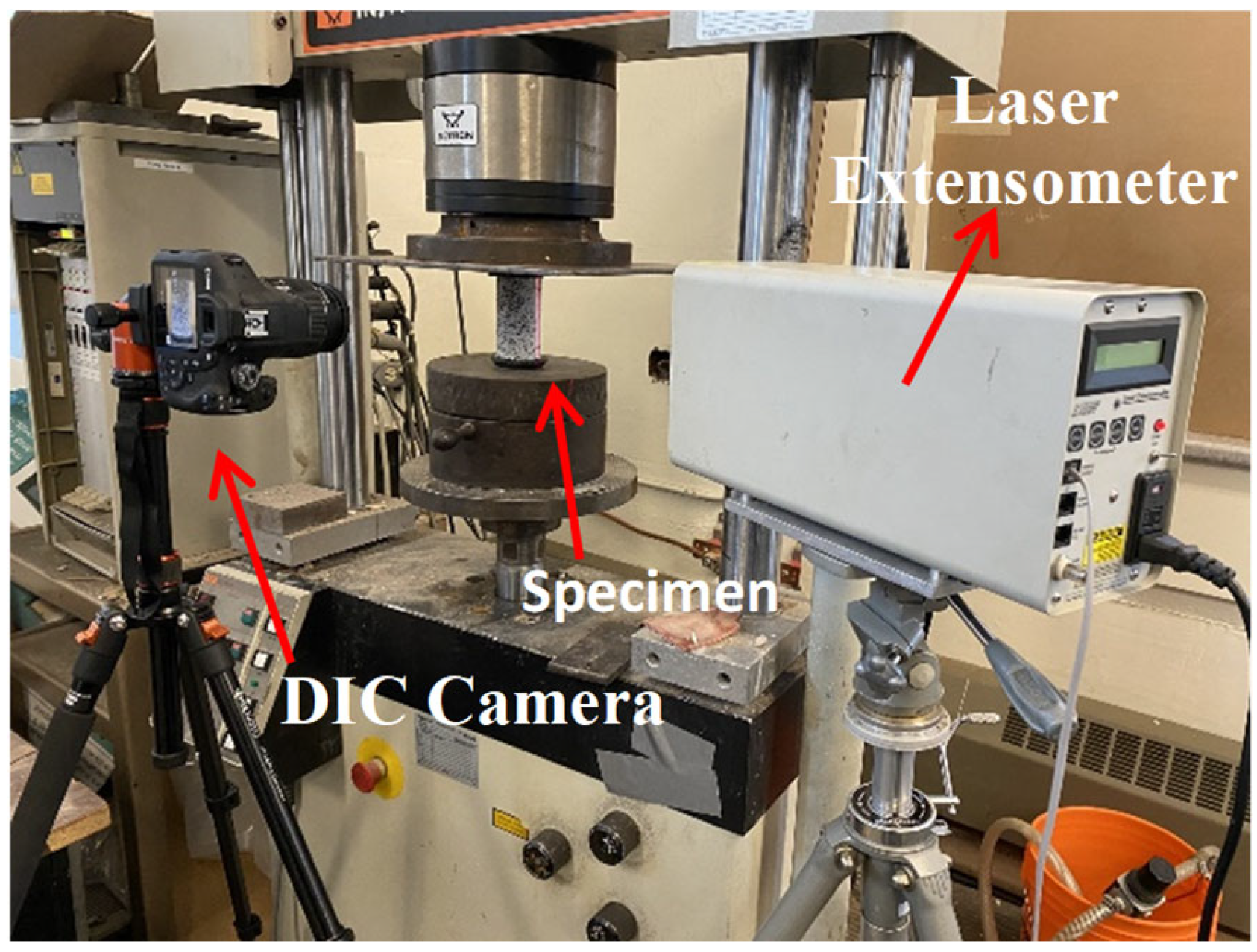
Compressive strength testing was conducted using a 100 kN universal Instron machine. To remain consistent with similitude laws, particularly the velocity scaling defined by Froude similitude (Equation (11)), the loading rate was adjusted to 0.5 mm/min. Specimens were carefully aligned using steel plates to prevent eccentric loading.
A reflective tape was applied to the specimen side to monitor deformation, and vertical displacement was recorded using an Electronic Instrument Research laser extensometer. The gauge length was scaled proportionally to match the 120 mm strain gauges used in the prototype tests, ensuring consistent strain measurement across specimen sizes. Additionally, all specimens were speckled with a black pattern over a white base coat to enable DIC analysis, similar to the prototype procedure.
Figure 4 illustrates the compressive strength test setup for the scaled-down model specimens.
Split tensile strength tests were also performed on the scaled-down cylindrical specimens following ASTM C496 [
36]. Steel bars with a diameter of 12.5 mm, scaled from the bars used in the prototype tensile tests, were placed along the top and bottom of the specimens to apply the splitting load evenly. DIC analysis captured the crack initiation and deformation behavior throughout the test.
5. Results and Discussion
This section comprehensively compares the mechanical performance between the prototype and scaled-down specimens. It examines the validity of the proposed scaled-down concrete mix by evaluating key mechanical properties, stress–strain behavior, failure modes, strain energy characteristics, and tensile behavior. All results are interpreted through the lens of Froude similitude, which governed the model’s design and evaluation.
5.1. Mechanical Properties Comparison
The comparative mechanical properties of the prototype and model specimens are presented in
Table 2. The average density (
) of the prototype specimens was 2454.3 ± 14 kg/m
3, while the scaled-down models achieved 2317.5 ± 1.3 kg/m
3, resulting in a deviation of only 5.57%. This small difference reflects similar internal void structures and constituent compactness, validating the consistency of the material mix design at both scales.
The compressive strength () of the prototype cylindrical specimens averaged 36.1 ± 1.1 MPa, which predicts a true model strength of 3.61 MPa under a 1:10 scale factor. The scaled-down cylinders achieved a compressive strength of 3.66 ± 0.19 MPa—just 1.42% higher than the ideal value. Similarly, the prismatic prototype specimens had a strength of 39.82 ± 0.4 MPa, while the scaled models reached 3.90 ± 0.02 MPa, representing a 1.97% difference. These results confirm that the model mix reliably reproduces compressive performance.
In terms of the tensile strength (), the prototype cylinders reached 3.51 ± 0.06 MPa (9.72% of their compressive strength), while the scaled-down cylinders recorded 0.348 ± 0.005 MPa (9.51% of their compressive strength). This 0.85% difference from the expected ratio underscores the accuracy of the scaled model in simulating tensile behavior.
The modulus of elasticity () was also consistent across scales. Prototype cylinders had an average modulus of 26.74 ± 2.3 GPa, while scaled-down specimens achieved 2.74 ± 0.16 GPa—only 2.51% different from the scaled prediction. Similarly, prismatic specimens demonstrated a modulus of 31.87 ± 2.5 GPa (prototype) and 3.41 ± 0.37 GPa (model), yielding a 7.04% deviation.
5.2. Stress–Strain Relationships and Failure Modes
The normalized stress–strain curves for cylindrical and prismatic specimens are shown in
Figure 5. These plots reveal strong agreement between prototype (P) and model (M) specimens throughout the elastic, elastic/plastic, and peak load ranges. In cylindrical specimens, the prototype peak strains were measured as 2103 × 10
−6 ± 33 × 10
−6 mm/mm (DIC) and 2070 × 10
−6 ± 45 × 10
−6 mm/mm (strain gauge, SG). The scaled-down specimens recorded nearly identical values of 2049 × 10
−6 ± 40 × 10
−6 mm/mm (DIC) and 2081 × 10
−6 ± 106 × 10
−6 mm/mm (laser extensometer).
Similarly, for prismatic specimens, the prototype strains were 1491 × 10−6 ± 76 × 10−6 mm/mm (DIC) and 1621 × 10−6 ± 55 × 10−6 mm/mm (strain gauge, SG), while the model specimens exhibited 1550 × 10−6 ± 58 × 10−6 mm/mm (DIC) and 1480 × 10−6 ± 88 × 10−6 mm/mm (laser extensometer). These results confirm that the scaled model accurately reflects the deformation behavior of the prototype.
To validate the accuracy of the strain results corresponding to the peak stresses, values from the model were compared to those predicted by various design codes and researchers. As shown in
Table 3, the differences between measured and predicted values ranged from 1.66% to 7.45%, with most deviations under 5%. These findings demonstrate that the scaled mix captures strains’ magnitude and evolution with high precision.
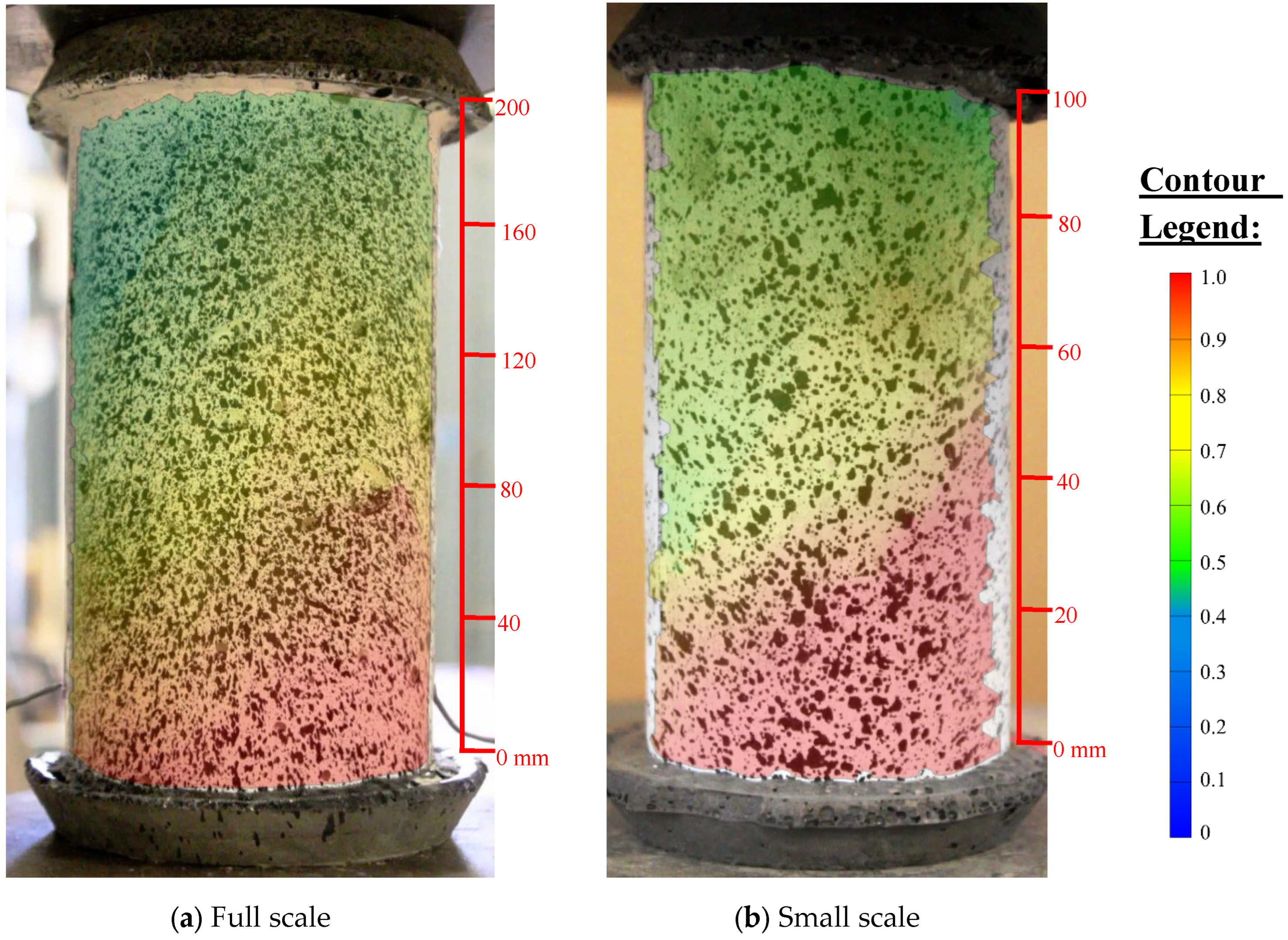
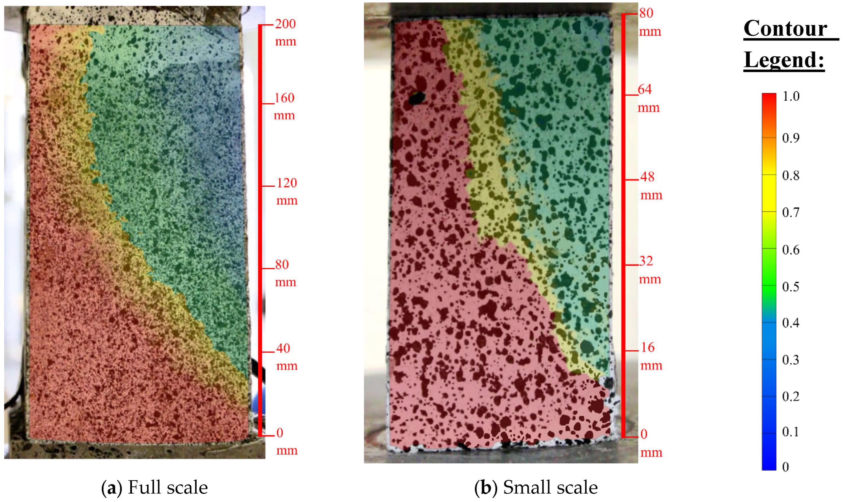
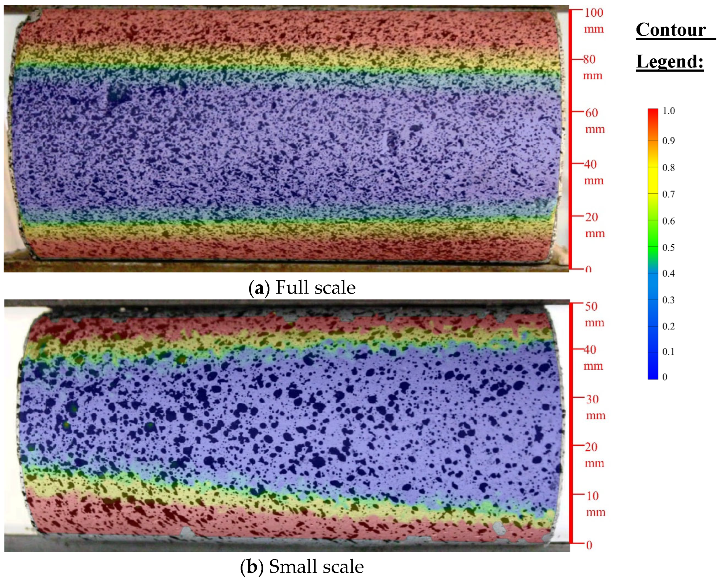
The deformation fields captured using Digital image correlation (DIC) are illustrated in
Figure 6 and
Figure 7. For cylindrical specimens,
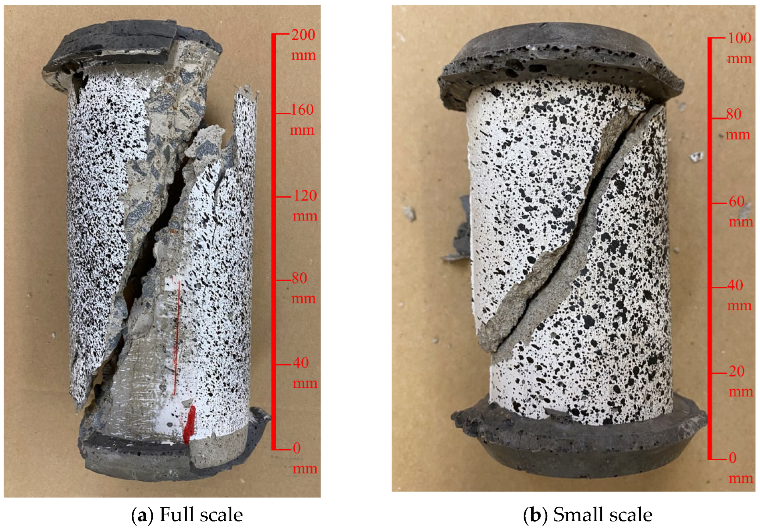
Figure 6 shows that the strain is localized in a shear band near the middle of the height, approximately one diameter away from the end plates, an outcome typical of Type 4 failure per ASTM C39 [
35], which is visually confirmed in
Figure 8. This diagonal shear failure results from friction at the specimen ends restricting lateral expansion, concentrating shear stresses at mid-height.
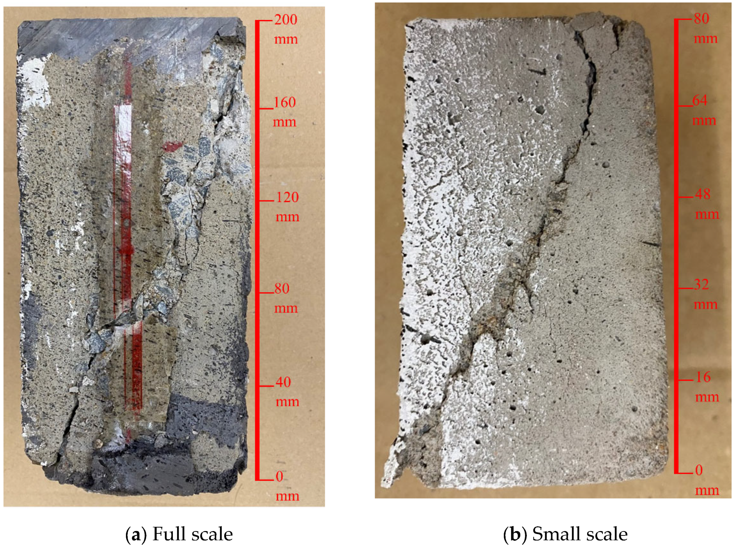
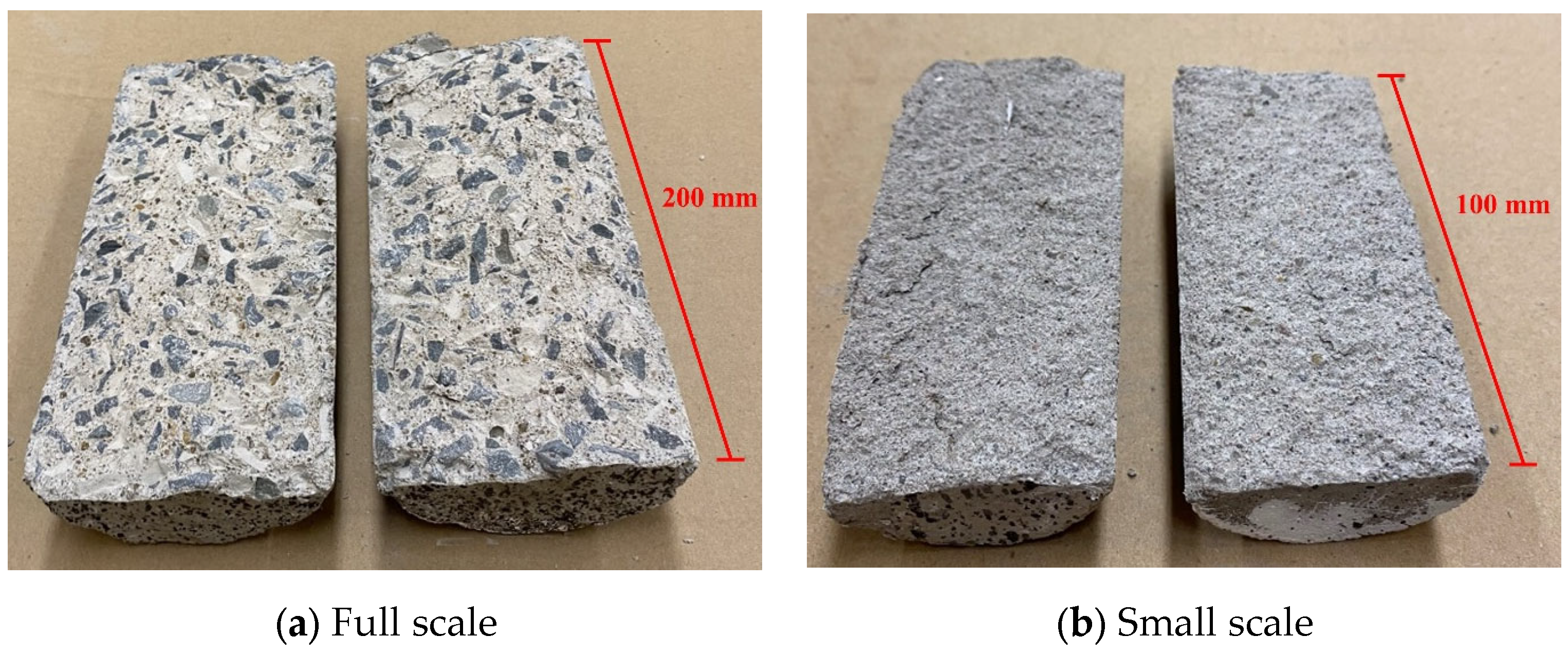
Figure 7 depicts inclined cracking for prismatic specimens, consistent with forming a shear damage belt. The fracture surfaces in
Figure 9 clearly show macroscopic inclined cracks passing through the mortar matrix and along aggregate boundaries. These cracks developed as adhesive cracks expanded and linked with internal cracks in the cement paste, forming the final failure surface. Such behavior aligns with observations by Cedolin et al. [
48] and Van Mier [
49], who demonstrated that crack coalescence and strain-softening govern tensile failure in concrete. Similarly, Bažant and Planas [
50] highlighted that fracture processes are strongly size-dependent, and accurate similitude requires scaled models to capture both pre-peak microcracking and post-peak softening. Recent studies using micro-CT and DEM simulation [
51] further confirm that aggregate size distribution influences crack initiation and propagation during splitting tests. The agreement between our scaled and prototype fracture patterns, therefore, confirms that the proposed mix design successfully reproduces critical fracture mechanisms, not only global stress–strain response.
Similarly, the consistency of dilatancy behavior is particularly interesting as it is a function of the concrete’s internal friction and associated volumetric strain. As the dilation angle correlates strongly with compressive strength, the 1.97% deviation between the model and prototype prisms suggests that this important inelastic characteristic was well preserved. Hence, the similarity of these patterns across scales supports the model’s capacity to reproduce geometric nonlinearity and failure modes with minimal distortion.
5.3. Strain Energy Density
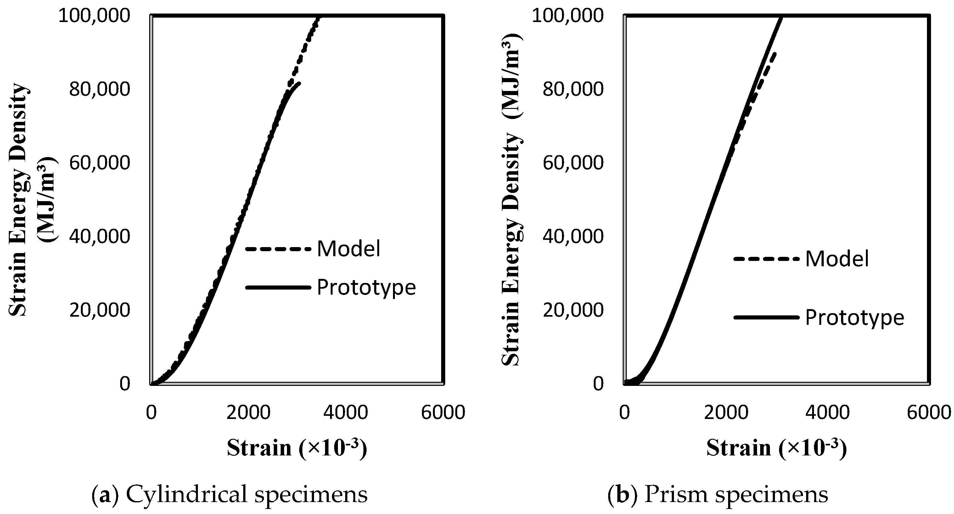
To further assess the scaled model’s accuracy, strain energy density was calculated for both specimen types and compared to prototype results after applying the appropriate scale factor for energy density under Froude similitude (i.e.,
). As shown in
Figure 10, the scaled energy density curves of the model specimens closely matched those of the prototype throughout both the elastic and inelastic deformation ranges. This agreement confirms that the model replicates stiffness and strength and mirrors the energy absorption characteristics of full-scale concrete.
5.4. Split Tensile Behavior
The split tensile behavior was investigated to confirm that the scaled concrete accurately replicates cracking patterns and failure mechanisms in tension.
Figure 11 presents the normalized displacement fields for prototype and scaled-down specimens during split tensile testing. Both specimen types exhibited vertical cracking along the central axis, with similar displacement intensity regions and deformation patterns. The physical fracture surfaces shown in
Figure 12 further affirm this similarity, with both models and prototypes failing by bifurcation initiated by microcracks along the aggregate–matrix interface.
These observations highlight that the scaled-down specimens captured the tensile cracking behavior of full-scale concrete with high fidelity. This observation is particularly significant since tensile strength governs crack initiation, affecting serviceability, durability, and ultimate capacity in reinforced concrete structures.
6. Proof-of-Concept
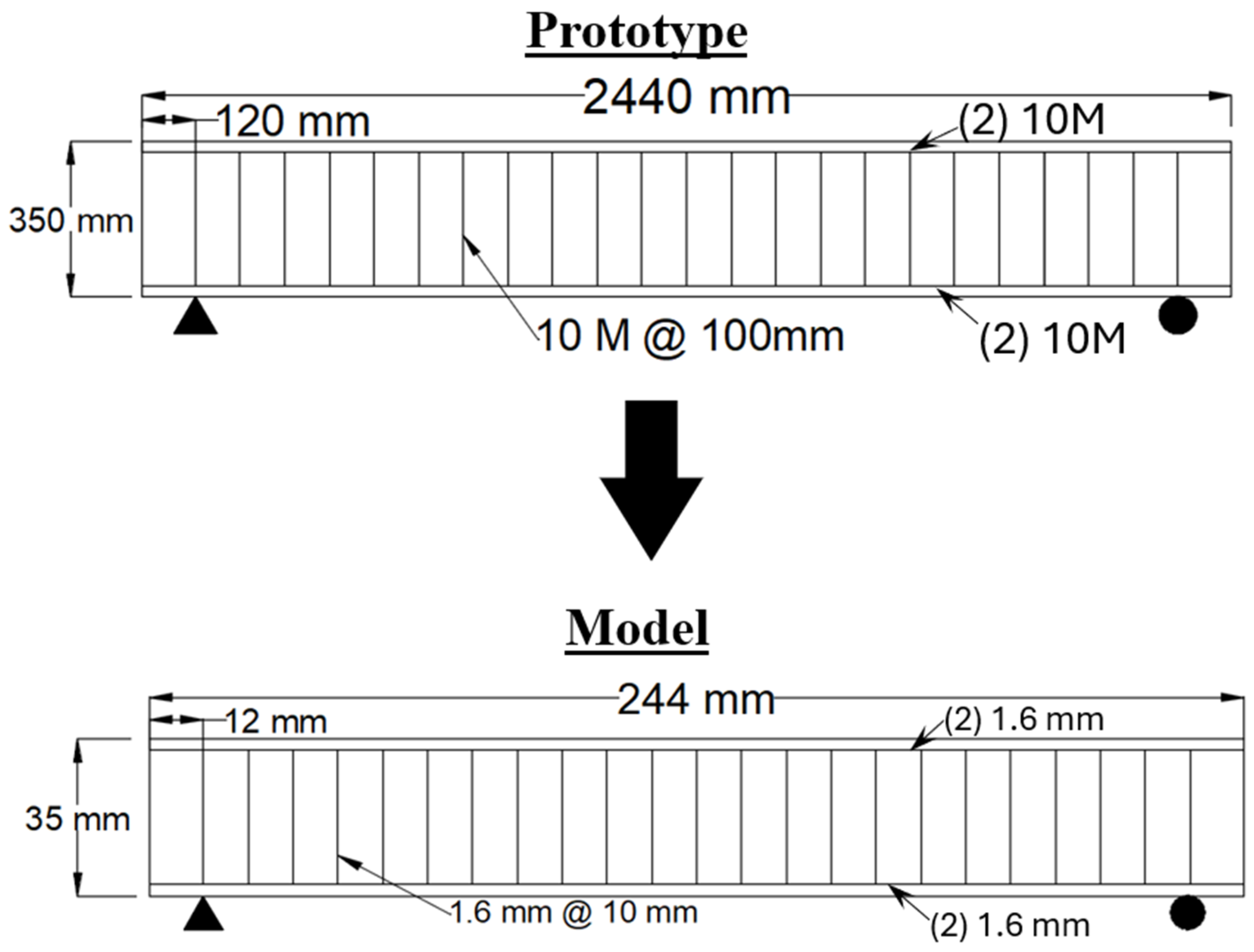
A proof-of-concept experimental program was conducted to further validate the effectiveness of the proposed scaled-down concrete mix and examine its applicability in structural modelling. This program involved fabricating and testing a full-scale reinforced concrete (RC) beam and a corresponding 1:10 scaled-down model beam. The goal was to assess whether the scaled-down mix could accurately reproduce the full-scale structural behavior under realistic loading conditions in compliance with Froude similitude.
The geometry and reinforcement layout for the prototype and model beams are shown in
Figure 13. The full-scale prototype beam was constructed using the same ordinary concrete mix described in
Section 4.1 and reinforced with conventional 10 M steel rebars. The measured yield and ultimate strengths of these rebars were 310.9 MPa and 447.5 MPa, respectively, as shown in
Figure 14. The scaled-down beam was fabricated using the developed simulant concrete mix from
Section 4.2. To simulate the mechanical response of steel reinforcement at the scaled level, 1.6 mm diameter metalwork silver-bearing soldering wires were selected. This material was chosen based on its low yield strength and high ductility, making it suitable for representing scaled reinforcement behavior without over-stiffening the model. The amount and arrangement of reinforcement were scaled per the Froude similitude requirements, where the force scale factor was determined as
, considering the length scale factor and density scale factor
and
.
The required number of reinforcement wires in the scaled-down beam was computed by scaling down the total yielding force in the prototype reinforcement [
15,
52,
53]. The detailing of the model beam followed the minimum reinforcement ratio requirements stipulated in CSA A23.3 [
30]. The mechanical response of the chosen model reinforcement material is illustrated in
Figure 15, confirming its suitability for achieving the desired yield behavior in the scaled domain.
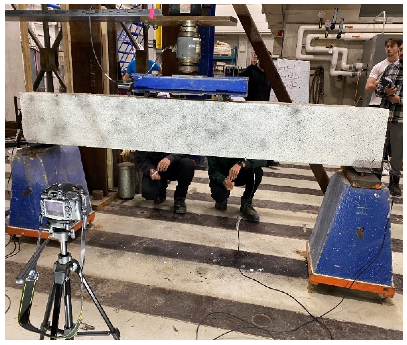
The full-scale beam was tested under four-point bending, as shown in
Figure 16. The loading was applied using a hydraulic actuator connected to a steel spreader beam, which transferred the load through two rollers spaced 500 mm apart. The beam was simply supported over a span of 1500 mm. The load was applied under displacement control at approximately 1.6 mm/min to ensure quasi-static conditions. Mid-span deflection was continuously measured using a linear variable differential transformer (LVDT).
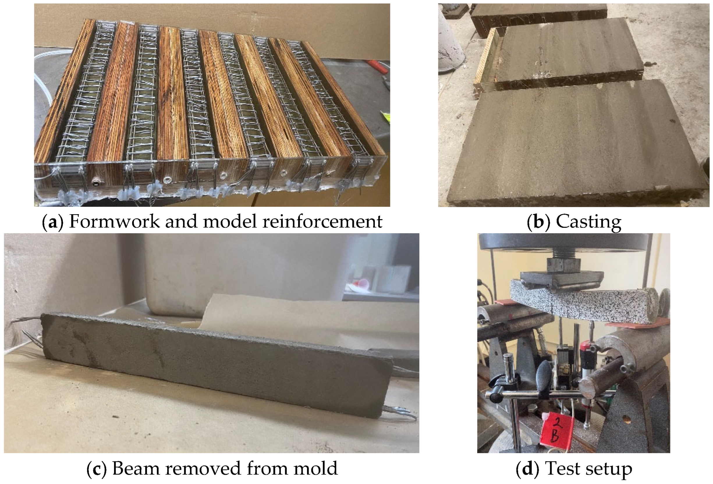
The scaled-down beam was fabricated with high precision using miniature molds constructed from Plexiglas and plywood, as shown in
Figure 17a. The scaled reinforcement was carefully positioned inside the molds (
Figure 17b), followed by casting with the scaled-down concrete mix. After curing, the model beam was de-molded (
Figure 17c), and the extended model rebar ends were capped using epoxy to limit any slippage occurring between the model concrete and reinforcement. The specimens were tested under a similarly scaled four-point bending configuration. The scaled-down setup used a miniature steel loading frame with rollers spaced 50 mm apart, and the total beam span was 150 mm. Loading was applied at a displacement rate of 0.5 mm/min, per the similitude-prescribed velocity scale factor
, consistent with Froude similitude laws (
Figure 17d). This scaling maintained the dynamic similarity between the model and prototype, ensuring comparable stress distributions and deformation responses.
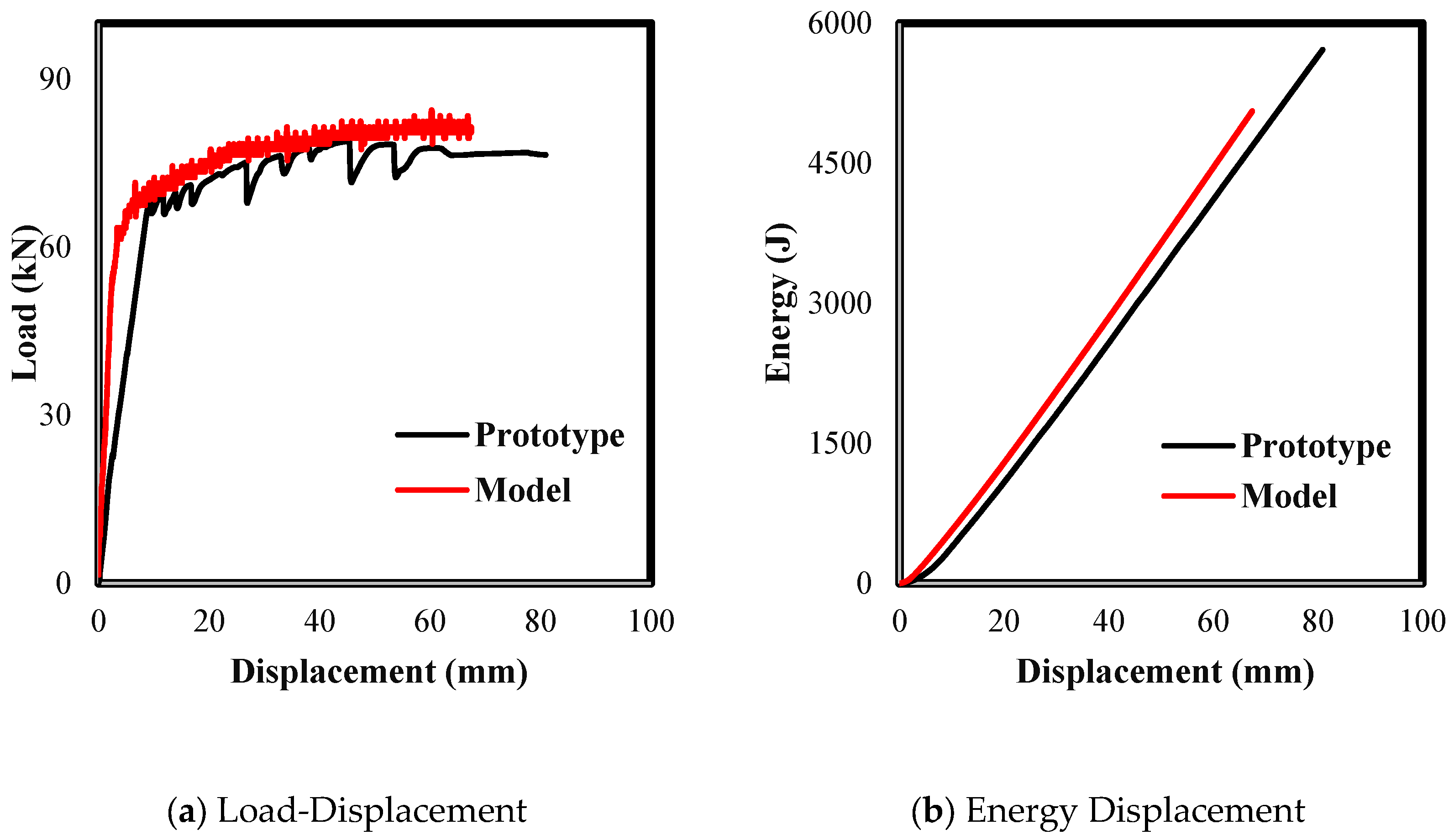
The experimental results in
Figure 18a show the load–displacement responses of both the prototype and model beams. The full-scale beam reached an ultimate load capacity of approximately 79 kN. The scaled-down beam reached a corresponding ultimate load of 84.5 N, which, when scaled up by the force scale factor of 1000, equates to 84.5 kN, demonstrating only a 7% deviation from the full-scale result. This close agreement validates the scaled model’s accuracy in replicating the prototype’s load-bearing capacity.
Regarding structural energy performance,
Figure 18b displays both beams’ energy–displacement curves. The model beam demonstrated comparable energy dissipation behavior across both elastic and inelastic stages of deformation. This behavior suggests that the scaled-down concrete mix accurately reproduces the full-scale beam’s behavior in terms of load and stiffness, energy absorption, and post-yield deformation.
These findings confirm that when applied under Froude similitude principles, the developed scaled-down concrete mix can successfully predict the flexural performance of reinforced concrete beams. The model accurately captured stiffness, ultimate strength, energy dissipation, and failure patterns, thereby reinforcing the validity of the scaled material and modelling approach. This proof-of-concept substantiates the broader applicability of the proposed mix design in scaled experimental investigations for reinforced concrete structures, offering a reliable alternative to costly full-scale testing.
7. Conclusions
This study introduced and validated a novel fine-grained concrete mix specifically engineered to support the physical modelling of reinforced concrete (RC) structures at a 1:10 scale, in full compliance with Froude similitude laws. The research addressed a longstanding challenge in structural modelling: the accurate replication of the nonlinear mechanical behavior of full-scale concrete using scaled-down materials without resorting to artificial gravity simulation methods, such as centrifuge testing.
Through a systematic experimental program, the proposed scaled-down mix was shown to closely match the prototype concrete’s essential mechanical properties, including density, compressive strength, tensile strength, and modulus of elasticity. The observed deviations from theoretical Froude-scaled values were minimal, with differences below 8% across all parameters. The experimental data confirmed that the developed material replicated the elastic and inelastic stress–strain behavior of full-scale specimens and captured strain energy characteristics and failure modes with high fidelity.
Digital image correlation (DIC) and laser extensometry revealed that the scaled-down specimens exhibited comparable deformation patterns, crack propagation, and failure mechanisms to those observed in full-scale specimens. The scaled mix successfully reproduced dilation effects, fracture morphology, and post-peak softening, further reinforcing its validity for realistic material behavior representation.
Moreover, a full-scale reinforced concrete beam and its scaled counterpart were tested under four-point bending to establish proof-of-concept. The results demonstrated a close match in load–displacement behavior and energy dissipation characteristics, with less than 7% deviation in ultimate capacity. The model beam reliably mirrored the structural performance of the prototype, thereby confirming the mix’s effectiveness in simulating full-scale RC behavior under flexural loading conditions.
The research establishes a critical advancement in developing reliable, scalable materials for physical modelling in structural engineering. The findings provide experimental evidence that when applied rigorously with a properly designed simulant concrete, Froude similitude can yield high-fidelity predictions of prototype structural behavior at significantly reduced cost and spatial demand.
While this study offers a robust methodological framework, future research is encouraged to explore the application of the proposed scaled-down concrete in more complex RC systems, including dynamic loading conditions such as seismic excitation and blast loads. Further investigation into the scalability of reinforced concrete elements with varying reinforcement configurations, geometrical irregularities, and boundary conditions will help extend the practical scope of this methodology. Such investigations could provide valuable insights into the behavior of scaled RC structures under extreme demands, where confinement, energy dissipation, and strain-rate sensitivity play a critical role. This extension would also support the application of similitude-based modelling to structural resilience assessment and advanced retrofitting strategies.
In this study, structural similitude was demonstrated primarily at the mechanical level through close agreement in compressive strength, tensile strength, modulus of elasticity, stress–strain behavior, and fracture morphology. Future research should incorporate direct microstructural analyses (e.g., pore distribution, XRD, SEM) to complement these findings and further validate the internal similarity of scaled and prototype concretes.
In conclusion, the study successfully demonstrates that using a tailored, low-strength concrete mix grounded in Froude similitude enables accurate and efficient structural modelling. This work contributes to experimental structural engineering and opens new avenues for cost-effective, reliable, and scalable physical modelling of reinforced concrete systems.
