Article

Mechanical Behavior Analysis of Pipe Roof Using Different Arrangements in Tunnel Construction

1
School of Highway, Chang’an University, Xi’an 710064, China
2
School of Civil Engineering, Lanzhou University of Technology, Lanzhou 730050, China
*
Authors to whom correspondence should be addressed.
Buildings 2025, 15(17), 3221; https://doi.org/10.3390/buildings15173221
Submission received: 3 July 2025 / Revised: 24 August 2025 / Accepted: 4 September 2025 / Published: 7 September 2025
(This article belongs to the Section Construction Management, and Computers & Digitization)

Abstract

For tunnels constructed in a single direction, the pipe roof at the tunnel exit portal can be installed either as Outside-to-Inside advanced support arrangements (Out–In ASA) or Inside-to-Outside advanced support arrangements (In–Out ASA). To investigate the pipe roof’s mechanical behavior and deformation characteristics under two excavation methods, this study establishes Pasternak two-parameter elastic foundation beam models for the pipe roof. Corresponding boundary conditions are proposed for each support configuration, and the governing differential equation for pipe roof deflection is derived and solved. The Hanjiashan Tunnel is used as an engineering case study to validate the theoretical results by comparing them with field monitoring data. A comparative analysis and parametric sensitivity study are then conducted for the two construction methods. The results show that theoretical predictions align well with the field measurements, confirming the validity of the proposed model. This study proposed calculation parameters for the Hanjiashan Tunnel. Under this circumstance, the method of Out–In ASA has been proven to offer improved structural performance and safety when the tunnel face is close to the portal. Moreover, the timely installation of the initial support and the strong bearing capacity of the surrounding rock can further reduce pipe roof deformation near the tunnel exit. Therefore, the Out–In ASA method is recommended for single-direction tunnel excavation. If the method of Out–In ASA is not feasible due to site constraints, the method of In–Out ASA can be adopted, while early support and effective grouting should be guaranteed to ensure control of excessive deformation. The findings of this study can provide a theoretical reference for the construction of tunnel portals in single-direction excavation.

1. Introduction

As the most common advanced support measure for a tunnel exit, the pipe roof has gained widespread application due to its extended longitudinal reinforcement range and effective support outcomes [1,2]. In recent years, scholars have conducted extensive research on the support mechanism of the pipe roof. This research encompasses analytical studies [3,4,5], field experiments [6,7], numerical simulations [8,9,10,11,12,13], and model experiments [14,15,16]. The representative achievements are as follows.
Bai et al. [17] and Chen et al. [18] conducted numerical simulations to investigate the deformation behavior of the pipe roof in various underground engineering contexts. Their studies demonstrated that advanced pipe roof support can effectively control ground surface displacement. In addition, grouting was found to enhance the initial support strength and limit the pipe roof deformation. Jia et al. [19,20], Wang et al. [21], and Lu et al. [22] conducted comprehensive studies on ground settlement and structural deformation induced by pipe roof construction, employing both field monitoring and numerical simulations. Li et al. [23] developed a mechanical model based on Winkler’s elastic foundation beam theory to analyze the stress and deformation of immersed tunnel structures. They pointed out that the Winkler foundation beam model could not provide accurate analysis results under large-deformation conditions. Chen et al. [24] indicated that the Winkler foundation beam model neglected the continuity of the foundation soil in their analysis of the mechanical behavior of feet-lock pipes. Finding these limitations, Fu et al. [25], Chen et al. [26], and Yang et al. [27] employed the Pasternak elastic foundation beam model under various construction scenarios and foundational assumptions to derive analytical solutions for pipe deformation induced by tunnel excavation.
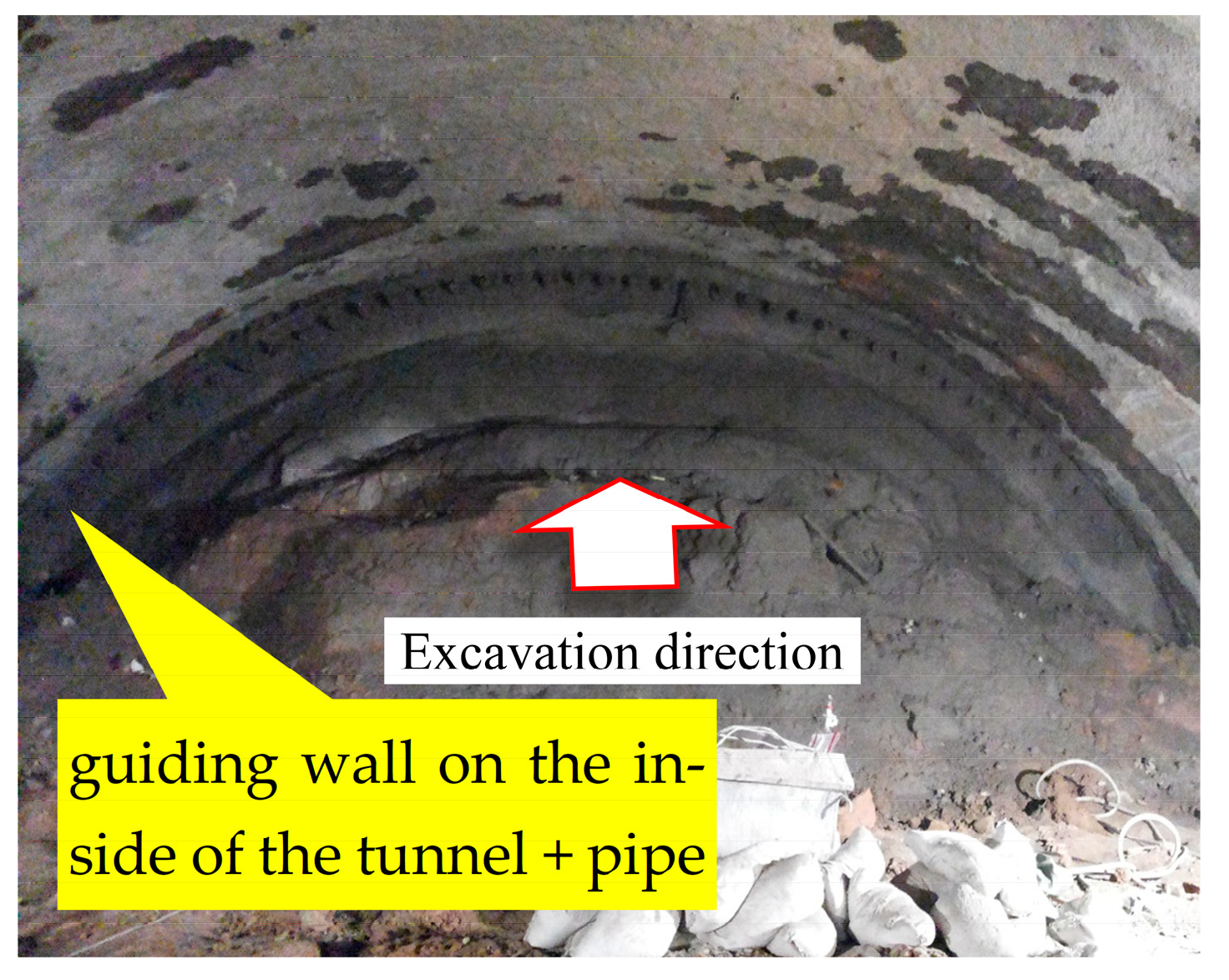
Most existing studies focus on the construction process at the tunnel entrance or within the main tunnel body, while relatively few have addressed the behavior of the pipe roof during the tunnel exit portal. Wu et al. [28] established Pasternak elastic foundation models for pipe roof support. Comparative analyses were performed with in situ deflection monitoring data. Subsequently, the deformation patterns of the pipe roof at the tunnel portal were analyzed. Similarly, our research team [29] conducted in situ monitoring of pipe roof settlement by using inclinometers. Based on the results of the field measurements, we used the Pasternak two-parameter elastic foundation beam model to explore pipe roof deformation patterns during tunnel exit construction and investigate the deformation mechanism of the pipe roof in the Hanjiashan Tunnel. Although these studies have investigated the construction of tunnel portals, they have primarily focused on Outside-to-Inside advanced support arrangements (Out–In ASA). In practice, unidirectionally excavated mountain tunnels often face challenges, such as steep terrain at the portal, limited construction space, poor accessibility, and difficulties in equipment mobilization. As a result, Inside-to-Outside advanced support arrangements (In–Out ASA) are also commonly employed in such scenarios. As illustrated in Figure 1 and Figure 2, the field situations of the two excavation methods are “arches on the outside of the tunnel + pipe roof” and “guiding wall on the inside of the tunnel + pipe roof”, respectively.
In summary, despite significant advancements in the mechanical modeling and application of pipe roof supports, a systematic analysis of how differing boundary conditions at the two ends under various excavation methods influence their mechanical behavior remains lacking. In the case of Out–In ASA, the pipe roof is anchored to the portal arch. It is assumed that the pipe roof end is fixed at the tunnel exit. In the case of Out–In ASA, the pipe roof end acts as a free end, resembling a cantilever structure. Obviously, the mechanical behavior of the pipe roof differs between the two excavation methods. Jiang et al. [30] and Wang et al. [31] pointed out that the pipe roof can provide preliminary support to the surrounding ground during shallow tunnel excavation, thereby mitigating adverse ground deformation caused by excavation. However, the pipe roof may not offer sufficient support in soft ground conditions, potentially resulting in surface settlement or even collapse above the tunnel. For mountain tunnels with unidirectional excavation, the geological conditions at the portal section are typically weak [32]. Therefore, it is essential to investigate the safety of advanced support arrangements at the tunnel exit to guide tunnel design and construction practices.
Based on one of the studies of our research team [29], this paper establishes Pasternak two-parameter elastic foundation beam models for two excavation methods at the tunnel portal. The calculated results are validated against field monitoring data. According to the mechanical parameters obtained from the Hanjiashan Tunnel, a parameter sensitivity analysis is conducted to evaluate the safety performance of In–Out ASA and Out–In ASA. The research findings aim to provide a theoretical basis for the design and construction of pipe roof support systems at the portal of mountain tunnels excavated unidirectionally.

2. Modeling Assumptions and Mechanical Models

2.1. Modeling Assumptions

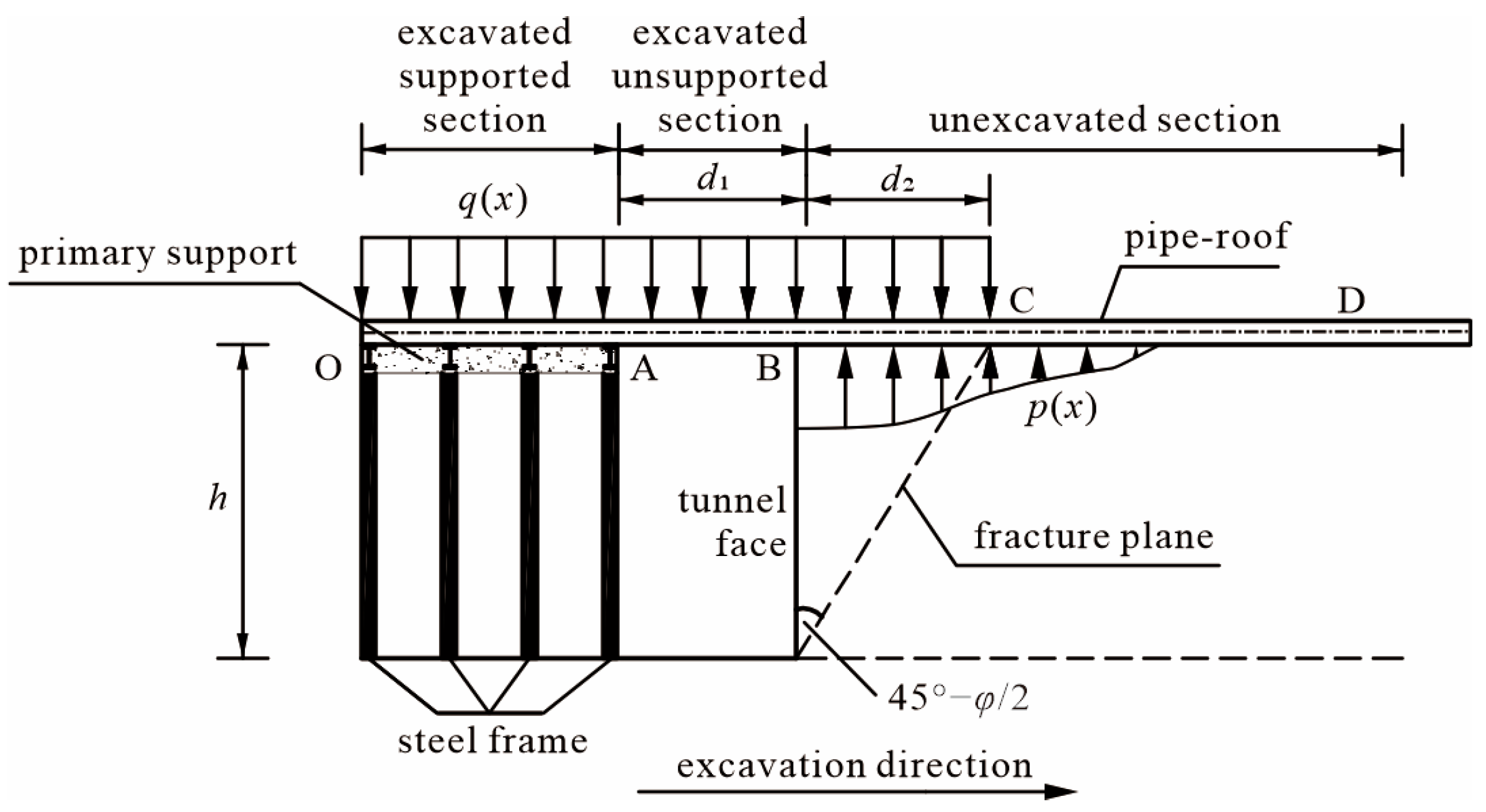
According to the construction process and the position of the tunnel face, the Pasternak two-parameter elastic foundation beam model of the pipe roof can be divided into four segments in the excavation direction, and the force diagram is shown in Figure 3.
As shown in Figure 3, the initial support section (OA) represents the joint load-bearing of the pipe roof and the initial support. After the completion of the initial support, the advanced support role of the pipe roof is fulfilled. The excavated unsupported section (AB) has a length represented by the excavation footage of one cycle, denoted as d1. The pipe roof bears the entire rock load q(x) and transfers this load to the initial support and the surrounding rock in front of the tunnel face. The disturbed section in front of the tunnel face (BC) has a length represented by the distance from the tunnel face to the maximum loosening range, denoted as d2. The pipe roof bears the rock load q(x) from above and experiences the foundation reaction p(x) from below. In the undisturbed section (CD), the pipe roof only experiences the effect of the foundation reaction p(x). In addition, φ represents the internal friction angle of the surrounding rock.
To establish the mechanical model, several assumptions are outlined as follows:
(1)
The pipe roof is modeled as a beam embedded in a Pasternak elastic foundation, while the viscoelastic response of the grouting materials and the creep behavior of the weak surrounding rock are neglected.
(2)
The maximum loosening range of the surrounding rock in front of the tunnel face (within the fracture plane) is considered as the range of longitudinal load acting on the pipe roof. The angle between the tunnel face and the fracture plane is 45° φ/2. Assuming the fracture plane starts at the toe of the slope in front of the tunnel face, the range of loads acting on the pipe roof in front of the tunnel face is determined as d = h × tan(45° φ/2).
(3)
The load q(x) is assumed to be uniformly distributed, and the pipe roof experiences zero surrounding rock pressure in the area where the surrounding rock is not loosened.
(4)
The pipe roof and the initial support jointly bear the pressure of the surrounding rock in the OA section. In the junction between the initial support and the pipe roof, the assumption is made that the pipe roof and initial support undergo deformation concurrently.
(5)
Considering the delayed effect of the initial support, point A can be considered as a fixed end with the certain initial displacement ω 0 and the rotation θ 0 . The value of initial displacement can be determined based on the measured settlement at this location.
(6)
The surrounding rock pressure is determined based on the formula provided in the “Specifications for Design of Highway Tunnels” (JTG D70-2004) [33].
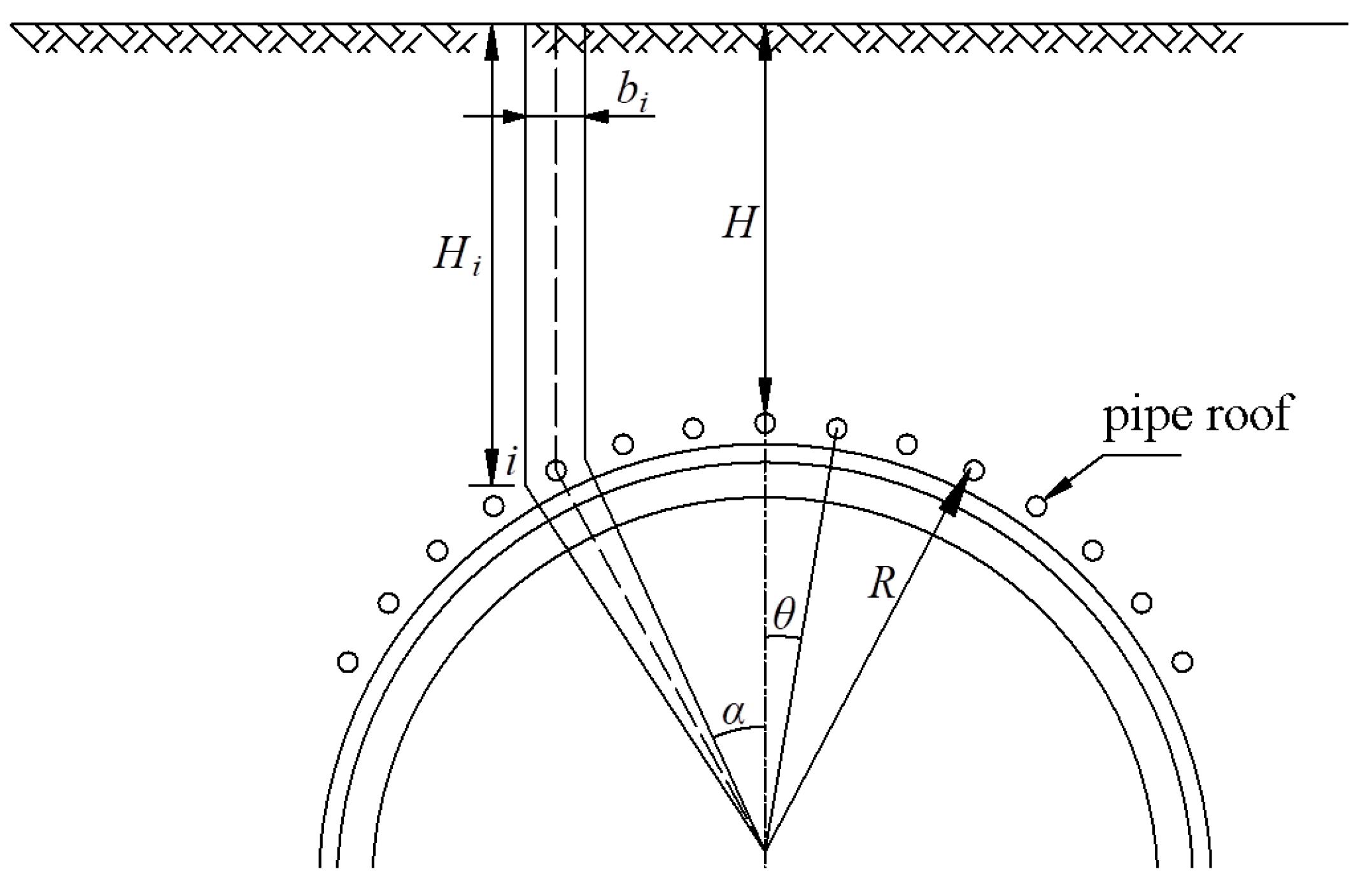
Furthermore, the pipe roof is arranged within a certain range on the tunnel arch, as shown in Figure 4. Assuming the support radius of the pipe roof is R, the spacing is S, the central angle between adjacent pipe roofs is θ, and the burial depth of the i-th pipe roof is Hi.
According to the geometric conditions, α = i 1 θ and δ = 2 R sin θ / 2 , the width of the soil acting on the i-th pipe roof and the burial depth of the i-th pipe roof are
b i = δ cos α
H i = H + R 1 cos α
In the vicinity of the tunnel face, where the burial depth H changes insignificantly, the longitudinal surrounding rock pressure q(x) on the pipe roof is considered as a uniformly distributed load. Thus, q i x = P × b i represents the load acting on the i-th pipe roof.

2.2. Mechanical Models of the Pipe Roof

(1)
Model establishment
Based on the distance between the tunnel face and the pipe roof end, the Pasternak two-parameter elastic foundation beam model of the pipe roof is considered in two models: (1) Model a: When the tunnel face is far from the pipe roof end, and the maximum loosening range of the surrounding rock has not reached the pipe roof end, the pipe roof can be treated as a semi-infinite elastic foundation beam. The schematic diagram of its mechanical model is shown in Figure 5a. (2) Model b: When the tunnel face is close to the pipe roof end, and the maximum loosening range of the surrounding rock is greater than the remaining length of the pipe roof, the pipe roof can be treated as a finite elastic foundation beam. The schematic diagram of its mechanical model is shown in Figure 5b [29].
(2)
Deflection differential equation
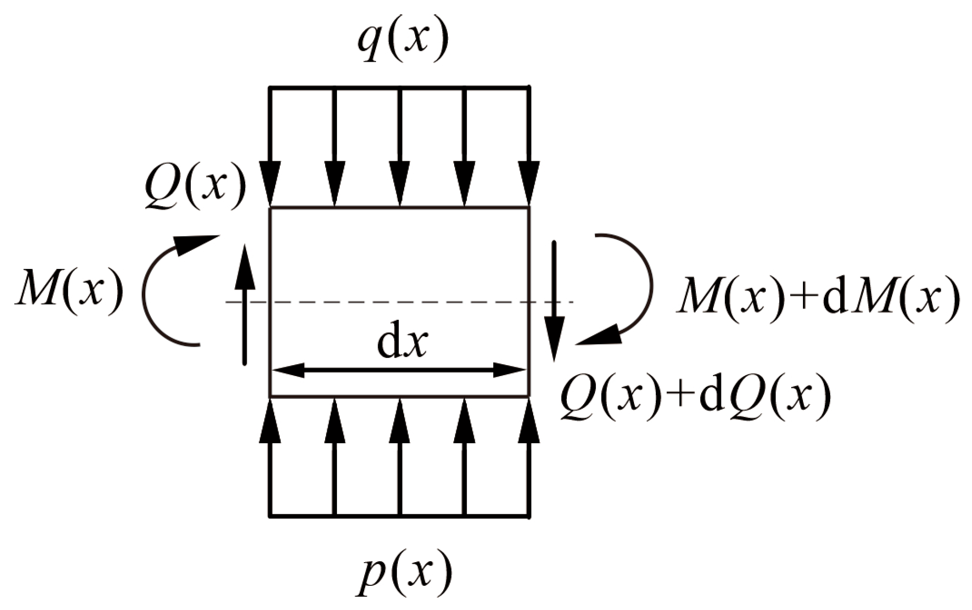
A micro-section of Pasternak’s two-parameter foundation beam model is taken and analyzed for stresses with the length of the micro-section as dx, which is shown in Figure 6. In the figure, Q(x) represents the shear force acting on the infinitesimal segment, and M(x) denotes the bending moment.
According to the equilibrium equation of the pipe roof segment, Bernoulli–Euler theory, and the relationship between deformation and load in the Pasternak two-parameter elastic foundation beam model, the expression can be derived as follows [29]:
E I d ω 4 x d x 4 G p b d ω 2 x d x 2 + k b ω x = b q x
where b* is the equivalent width of the beam, and b = b + G p / k ; b is the width of the Pasternak elastic foundation beam; E is the elastic modulus of the pipe roof; I is the inertia moment of the pipe roof; and Gp is the shear stiffness of the elastic foundation layer. When Gp = 0, the model degenerates into the Winkler foundation model; k is the coefficient of the foundation reaction; and ω x is the deflection of the pipe roof.
According to the mechanical model of the pipe roof, the differential equations for the deflection of the pipe roof in different sections are as follows [29]:
(1)
Model a
Section AB: Substituting p(x) = 0, q(x) = q0 into Equation (3), the deflection differential equation in AB section can be obtained:
E I d ω 4 ( x ) d x 4 = b q 0
Section BC: Substituting q(x) = q0 into Equation (3), the deflection differential equation in BC section can be obtained:
E I d ω 4 x d x 4 G p b d ω 2 x d x 2 + k b ω x = b q 0
Section CD: Substituting q(x) = 0 into Equation (3), the deflection differential equation in CD section can be obtained:
E I d ω 4 x d x 4 G p b d ω 2 x d x 2 + k b ω x = 0
(2)
Model b
The deflection differential equations for AB and BC sections are the same as in Model a, as shown in Equations (4) and (5).

3. Solution of the Elastic Foundation Beam Model

3.1. Solution of the Deflection Differential Equations for the Pipe Roof

(1)
Model a
Section AB: The characteristic equation for the deflection differential equation E I d ω 4 ( x ) d x 4 = b q 0 is r4 = 0, with a quadruple root r = 0. The homogeneous equation’s general solution is ω ( x ) = N1x3 + N2x2 + N3x + N4. The particular solution for a uniform load of q0 is ω = q 0 x 4 24 E I , and the general solution is
ω 1 ( x ) = q 0 24 E I x 4 + N 1 x 3 + N 2 x 2 + N 3 x + N 4
where N1 ~ N4 are undetermined coefficients.
Section CD: Let λ 4 = k b 4 E I , then Equation (6) can be written as follows:
1 4 d ω 4 ( x ) d x 4 G p λ 4 k d ω 2 ( x ) d x 2 + λ 4 ω ( x ) = 0
The characteristic equation can be given as
1 4 r 4 G p λ 4 k r 2 + λ 4 = 0
Usually, k >> Gp and λ < 1, so Gp λ 2 /k < 1; therefore, the characteristic equation has two pairs of complex roots. The general solution for Equation (8) can be obtained as
ω 3 ( x ) = e α x ( N 5 cos β x + N 6 sin β x ) + e α x ( N 7 cos β x + N 8 sin β x )
where N5 ~ N8 are undetermined coefficients and are the complex conjugate roots of Equation (9); α = λ 1 + G p λ 2 / k ; β = λ 1 G p λ 2 / k .
Section BC: Since the deflection differential equation of CD section is the homogeneous equation of the deflection differential equation of BC section, the general solution for Equation (5) can be derived as
ω 2 ( x ) = e α x ( N 5 cos β x + N 6 sin β x ) + e α x ( N 7 cos β x + N 8 sin β x ) + ω 2
Based on ω 2 x = d 1 + d 2 = ω 3 x = d 1 + d 2 and ω 2 x = d 1 + d 2 = ω 3 x = d 1 + d 2 , the particular solution ω 2 related to q(x) and its boundary conditions can be derived as
ω 2 = q 0 k b 1 cosh β ( x d 1 d 2 ) cos β ( x d 1 d 2 )
(2)
Model b
Section AB: The general solution for the deflection differential equation is given by Equation (7).
Section BC: The general solution for the deflection differential equation is given by Equation (11).

3.2. Deflection Equation of Pipe Roof: In–Out ASA

When using the method of In–Out ASA, it is assumed that the pipe roof is unconstrained at the tunnel exit, acting as a free end.
(1)
Model a
Point A is a fixed end with a certain initial displacement ω 0 and rotation θ 0 . At point B, the pipe roof satisfies the continuity condition. At point C, since the tunnel face is far from the pipe roof end, the pipe roof is considered as a semi-infinite elastic foundation beam, and therefore, it is treated as a fixed end with zero displacement and rotation. In summary, the boundary conditions for Model a are as follows:
ω 1 x = 0 = ω 0 ,   θ 1 x = 0 = ω 1 x = 0 = θ 0 ,   ω 1 x = d 1 = ω 2 ­ x = d 1 ,   ω 1 x = d 1 = ω 2 ­ x = d 1 ,   ω 1 x = d 1 = ω 2 ­ x = d 1 ,   ω 1 x = d 1 = ω 2 ­ x = d 1 ,   ω 3 x = 0 ,   θ 3 x = 0
N 5 = N 6 = 0 can be directly derived from ω 3 x = 0 and θ 3 x = 0 .
Substituting the above boundary conditions into Equations (7)–(12), we obtain
0 0 0 1 0 0 0 0 1 0 0 0 d 1 3 d 1 2 d 1 1 P 35 P 36 3 d 1 2 2 d 1 1 0 P 45 P 46 6 d 1 2 0 0 P 55 P 56 6 0 0 0 P 65 P 66 N 1 N 2 N 3 N 4 N 7 N 8 = ω 0 θ 0 ψ 3 ψ 4 ψ 5 ψ 6
P 35 = e α d 1 cos β d 1 P 36 = e α d 1 sin β d 1
P 45 = e α d 1 α cos β d 1 + β sin β d 1 P 46 = e α d 1 α sin β d 1 β cos β d 1
P 55 = e α d 1 2 α β sin β d 1 α 2 β 2 cos β d 1 P 56 = e α d 1 2 α β cos β d 1 α 2 β 2 sin β d 1
P 65 = e α d 1 β 3 3 α 2 β sin β d 1 + α 3 3 α β 2 cos β d 1 P 66 = e α d 1 β 3 3 α 2 β cos β d 1 + α 3 3 α β 2 sin β d 1
ψ 3 = q 0 d 1 4 24 E I + q 0 k b 1 cos β d 2 cosh β d 2
ψ 4 = q 0 d 1 3 6 E I + β q 0 k b [ cos β d 2 sinh β d 2 cosh β d 2 sin β d 2 ]
ψ 5 = q 0 d 1 2 2 E I + 2 β 2 q 0 k b sin β d 2 sinh β d 2
ψ 6 = q 0 d 1 E I 2 β 3 q 0 k b [ cosh β d 2 sin β d 2 + cos β d 2 sinh β d 2 ]
where Pij represents the offset correction terms caused by the elastic foundation reaction. ψ3 ~ ψ6 correspond to the target values related to displacement, rotation, bending moment, and shear force, respectively.
Using MATLAB software in version R2024b, calculate the coefficients N1 ~ N4 and N7, N8 in Equation (13), then substitute them into the deflection differential equations for different sections of Model a, resulting in the deflection differential equation for Model a.
(2)
Model b
The boundary conditions at points A and B are the same as those for Model a.
At point C, since the tunnel face is close to the pipe roof end, it is considered as a finite-length elastic foundation beam. It is assumed that the pipe roof is unconstrained at the tunnel exit and treated as a free end, the boundary conditions are as follows:
ω 2 x = d 1 + d 2 = 0 ,   ω 2 x = d 1 + d 2 = 0
Substituting the above boundary conditions into Equations (7)–(12), we obtain:
0 0 0 1 0 0 0 0 0 0 1 0 0 0 0 0 d 1 3 d 1 2 d 1 1 P 35 ­ P 36 ­ P 37 ­ P 38 ­ 3 d 1 2 2 d 1 1 0 P 45 ­ P 46 ­ P 47 ­ P 48 ­ 6 d 1 2 0 0 P 55 ­ P 56 ­ P 57 ­ P 58 ­ 6 0 0 0 P 65 ­ P 66 ­ P 67 ­ P 68 ­ 0 0 0 0 P 75 ­ P 76 ­ P 77 ­ P 78 ­ 0 0 0 0 P 85 ­ P 86 ­ P 87 ­ P 88 ­ N 1 N 2 N 3 N 4 N 5 N 6 N 7 N 8 = ω 0 θ 0 ψ 3 ψ 4 ψ 5 ψ 6 0 0
P 35 ­ = e α d 1 cos β d 1 P 36 ­ = e α d 1 sin β d 1 P 37 ­ = e α d 1 cos β d 1 P 38 ­ = e α d 1 sin β d 1
P 45 ­ = e α d 1 β sin β d 1 α cos β d 1 P 46 ­ = e α d 1 α sin β d 1 + β cos β d 1 P 47 ­ = e α d 1 α cos β d 1 + β sin β d 1 P 48 ­ = e α d 1 α sin β d 1 β cos β d 1
P 55 ­ = e α d 1 2 α β sin β d 1 + β 2 α 2 cos β d 1 P 56 ­ = e α d 1 β 2 α 2 sin β d 1 2 α β cos β d 1 P 57 ­ = e α d 1 2 α β sin β d 1 + β 2 α 2 cos β d 1 P 58 ­ = e α d 1 β 2 α 2 sin β d 1 + 2 α β cos β d 1
P 65 ­ = e α d 1 β 3 + 3 α 2 β sin β d 1 + 3 α β 2 α 3 cos β d 1 P 66 ­ = e α d 1 β 3 3 α 2 β cos β d 1 + 3 α β 2 α 3 sin β d 1 P 67 ­ = e α d 1 β 3 + 3 α 2 β sin β d 1 + α 3 3 α β 2 cos β d 1 P 68 ­ = e α d 1 β 3 3 α 2 β cos β d 1 + α 3 3 α β 2 sin β d 1
P 75 ­ = e α ( d 1 + d 2 ) 2 α β sin β ( d 1 + d 2 ) + α 2 β 2 cos β ( d 1 + d 2 ) P 76 ­ = e α ( d 1 + d 2 ) α 2 β 2 sin β ( d 1 + d 2 ) + 2 α β cos β ( d 1 + d 2 ) P 77 ­ = e α ( d 1 + d 2 ) 2 α β sin β ( d 1 + d 2 ) + α 2 β 2 cos β ( d 1 + d 2 ) P 78 ­ = e α ( d 1 + d 2 ) α 2 β 2 sin β ( d 1 + d 2 ) 2 α β cos β ( d 1 + d 2 )
P 85 ­ = e α ( d 1 + d 2 ) β 3 3 α 2 β sin β ( d 1 + d 2 ) + α 3 3 α β 2 cos β ( d 1 + d 2 ) P 86 ­ = e α ( d 1 + d 2 ) 3 α 2 β β 3 cos β ( d 1 + d 2 ) + α 3 3 α β 2 sin β ( d 1 + d 2 ) P 87 ­ = e α ( d 1 + d 2 ) β 3 3 α 2 β sin β ( d 1 + d 2 ) + 3 α β 2 α 3 cos β ( d 1 + d 2 ) P 88 ­ = e α ( d 1 + d 2 ) 3 α 2 β β 3 cos β ( d 1 + d 2 ) + 3 α β 2 α 3 sin β ( d 1 + d 2 )
ψ 3 , ψ 4 , ψ 5 , and ψ 6 are denoted as Equations (18)–(21).
Calculate the coefficients M1 ~ M4 and N1 ~ N4 in Equation (22), then substitute them into the deflection differential equations for different sections of Model b, resulting in the deflection differential equation for Model b.

3.3. Deflection Equation of Pipe Roof: Out–In ASA

When employing the method of Out–In ASA, the pipe roof is anchored to the portal arch. It is assumed that the pipe roof end is fixed at the tunnel exit [29].
(1)
Model a
The Pasternak two-parameter elastic foundation beam model for the Out–In ASA is the same as the model for In–Out ASA.
(2)
Model b
At point C, since the tunnel face is close to the end of the pipe roof and the pipe roof is anchored to the portal arch, it is modeled as a finite-length elastic foundation beam with a fixed boundary condition at the tunnel exit. Thus, the boundary conditions of point C for Model b are as follows:
ω 2 x = d 1 + d 2 = 0 ,   ω 2 x = d 1 + d 2 = 0
Substituting the above boundary conditions into Equations (7)–(12), we obtain
0 0 0 1 0 0 0 0 0 0 1 0 0 0 0 0 d 1 3 d 1 2 d 1 1 P 35 ­ P 36 ­ P 37 ­ P 38 ­ 3 d 1 2 2 d 1 1 0 P 45 ­ P 46 ­ P 47 ­ P 48 ­ 6 d 1 2 0 0 P 55 ­ P 56 ­ P 57 ­ P 58 ­ 6 0 0 0 P 65 ­ P 66 ­ P 67 ­ P 68 ­ 0 0 0 0 P 75 ­ P 76 ­ P 77 ­ P 78 ­ 0 0 0 0 P 85 ­ P 86 ­ P 87 ­ P 88 ­ M 1 M 2 M 3 M 4 N 1 N 2 N 3 N 4 = ω 0 θ 0 ψ 3 ψ 4 ψ 5 ψ 6 0 0
According to its equations and boundary conditions, it can be observed that P35′ ~ P38′, P45′ ~ P48′, P55′ ~ P58′, and P65′ ~ P68′ denoted as Equations (23)–(26); ψ 3 , ψ 4 , ψ 5 , and ψ 6 are denoted as Equations (18)–(21).
P 75 ­ = e α ( d 1 + d 2 ) cos β ( d 1 + d 2 ) P 76 ­ = e α ( d 1 + d 2 ) sin β ( d 1 + d 2 ) P 77 ­ = e α ( d 1 + d 2 ) cos β ( d 1 + d 2 ) P 78 ­ = e α ( d 1 + d 2 ) sin β ( d 1 + d 2 )
P 85 ­ = e α ( d 1 + d 2 ) α cos β ( d 1 + d 2 ) β sin β ( d 1 + d 2 ) P 86 ­ = e α ( d 1 + d 2 ) α sin β ( d 1 + d 2 ) + β cos β ( d 1 + d 2 ) P 87 ­ = e α ( d 1 + d 2 ) α cos β ( d 1 + d 2 ) β sin β ( d 1 + d 2 ) P 88 ­ = e α ( d 1 + d 2 ) α sin β ( d 1 + d 2 ) + β cos β ( d 1 + d 2 )

4. General Situation of Construction and Measured Results

4.1. Topography and Geology

The Hanjiashan Tunnel, situated along the Tongxun Highway, is a separated four-lane tunnel with two directions of traffic. The left line spans from station ZK208 + 650 to ZK209 + 535, with a length of 885 m. The right line spans from station YK208 + 620 to YK209 + 485, with a length of 865 m. The tunnel is designed for a speed of 80 km/h, with a clear width of 10.25 m and a clear height of 5 m.
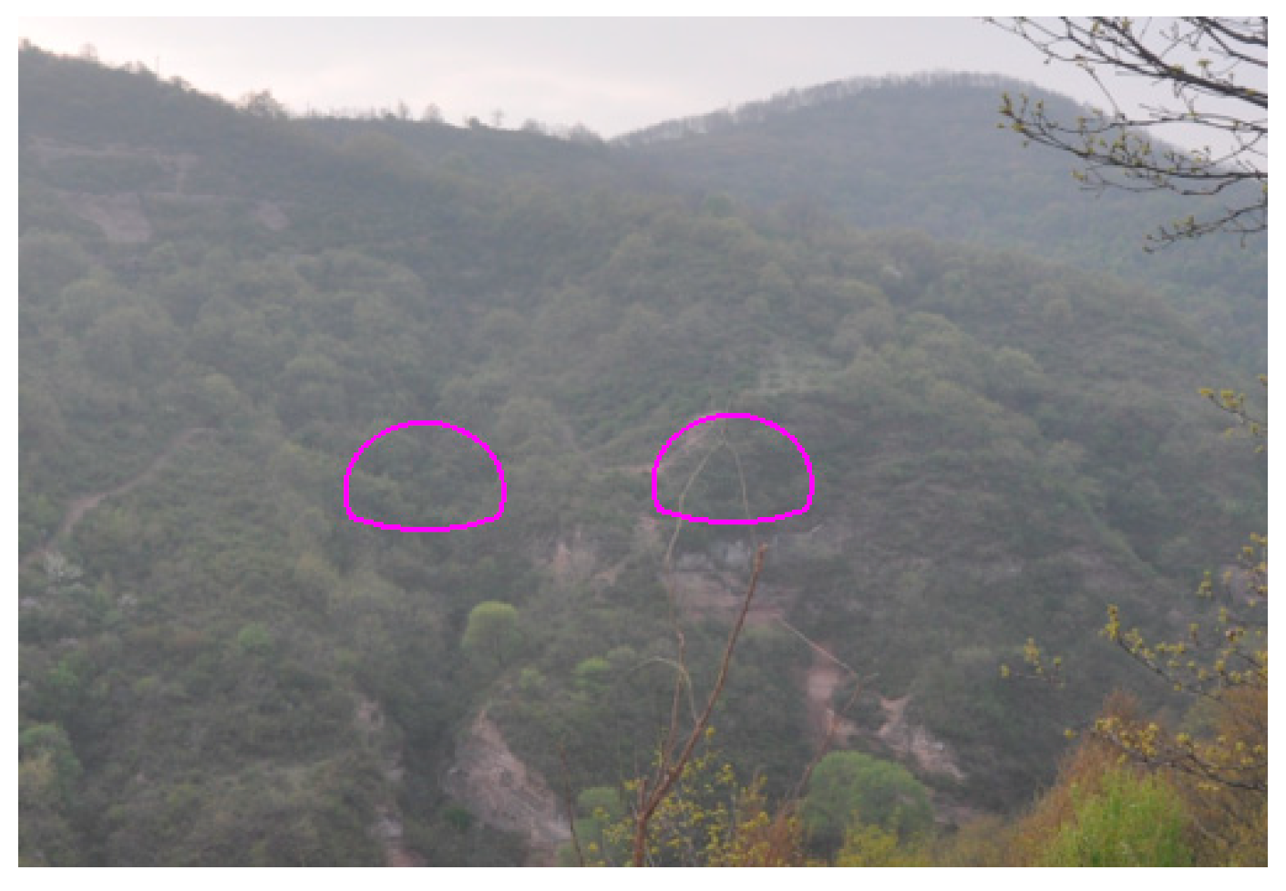
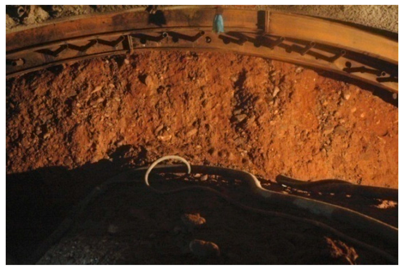
The tunnel is excavated in a single direction. The entrance is situated on a rocky slope with a natural gradient of approximately 40°. The overall stability of the slope is satisfactory, as illustrated in Figure 7. The geological strata at the tunnel site primarily consist of residual silty clay, fully weathered sandstone, conglomerate, and mudstone. At the tunnel entrance, the ground surface is covered by a thin layer of residual slope deposits composed of fine-grained clay. The surrounding rock mainly comprises heavily weathered sandstone (with interbedded mudstone) from the Cretaceous period, occasionally containing conglomerates. The rock mass is classified as Grade V. The geological conditions of the surrounding rock are depicted in Figure 8.

4.2. Design and Construction of the Left-Line Tunnel Entrance

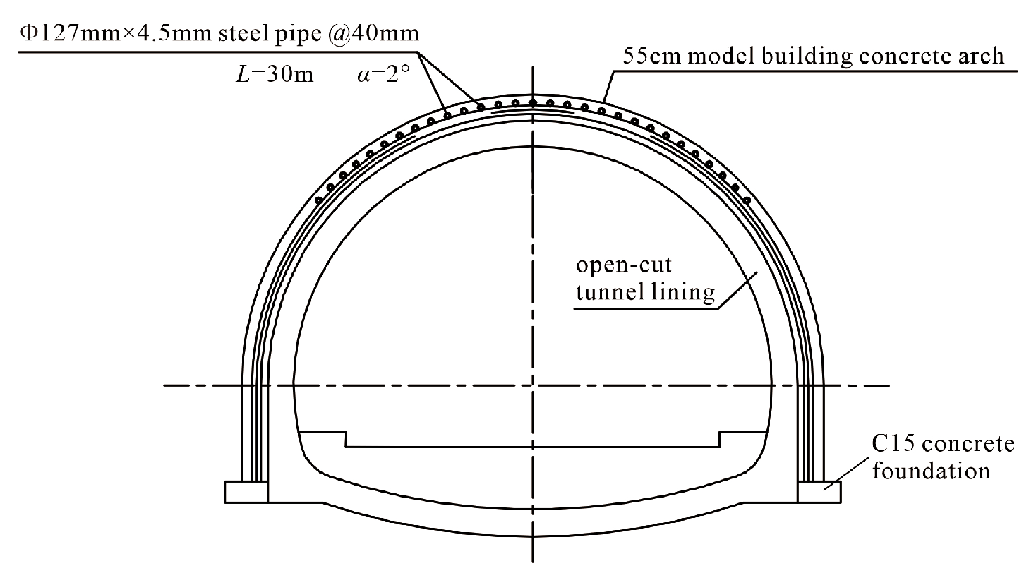
The left-line entrance of Hanjiashan Tunnel adopts the Out–In ASA method. The advanced support adopts Φ127 × 4.5 mm pipe roof with a length of 30 m (from ZK208 + 658 to ZK208 + 688), circumferential spacing of 40 cm. The steel pipes are grouted using M30 cement mortar. The design diagram of the advanced support system is illustrated in Figure 9, and the on-site construction is depicted in Figure 10.
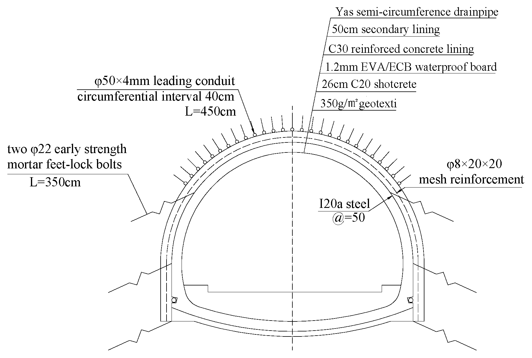
The tunnel structure adopts a composite lining, as shown in Figure 11. The initial support includes Φ22 early-strength mortar rock bolts, I20a steel, Φ8 steel mesh, and 26 cm thick C20 shotcrete. The secondary lining consists of 50 cm thick cast-in-place reinforced concrete. The tunnel entrance section typically consists of weak surrounding rock, and to ensure construction safety, methods such as sectional excavation or the bench method are often employed. Sectional excavation techniques, such as the CD or CRD method, are generally used for large cross-section tunnels but involve numerous procedures and complex structural forces [34]. Therefore, the three-step seven-bench excavation method was chosen for the Hanjiashan Tunnel entrance section from both safety and economic perspectives.

4.3. Measured Results Analysis of the Left-Line Tunnel Entrance

The deformation of the pipe roof during tunnel construction was monitored on-site using a CX–4C series inclinometer (Ji Shen Oblique Testerco., LTD., Wuhan, China). An inclinometer casing was embedded within the pipe roof at the tunnel crown, with an effective monitoring length of 20 m. A settlement reference point was established at the casing opening, and displacement measurements were taken at intervals of 0.5 m along the length.
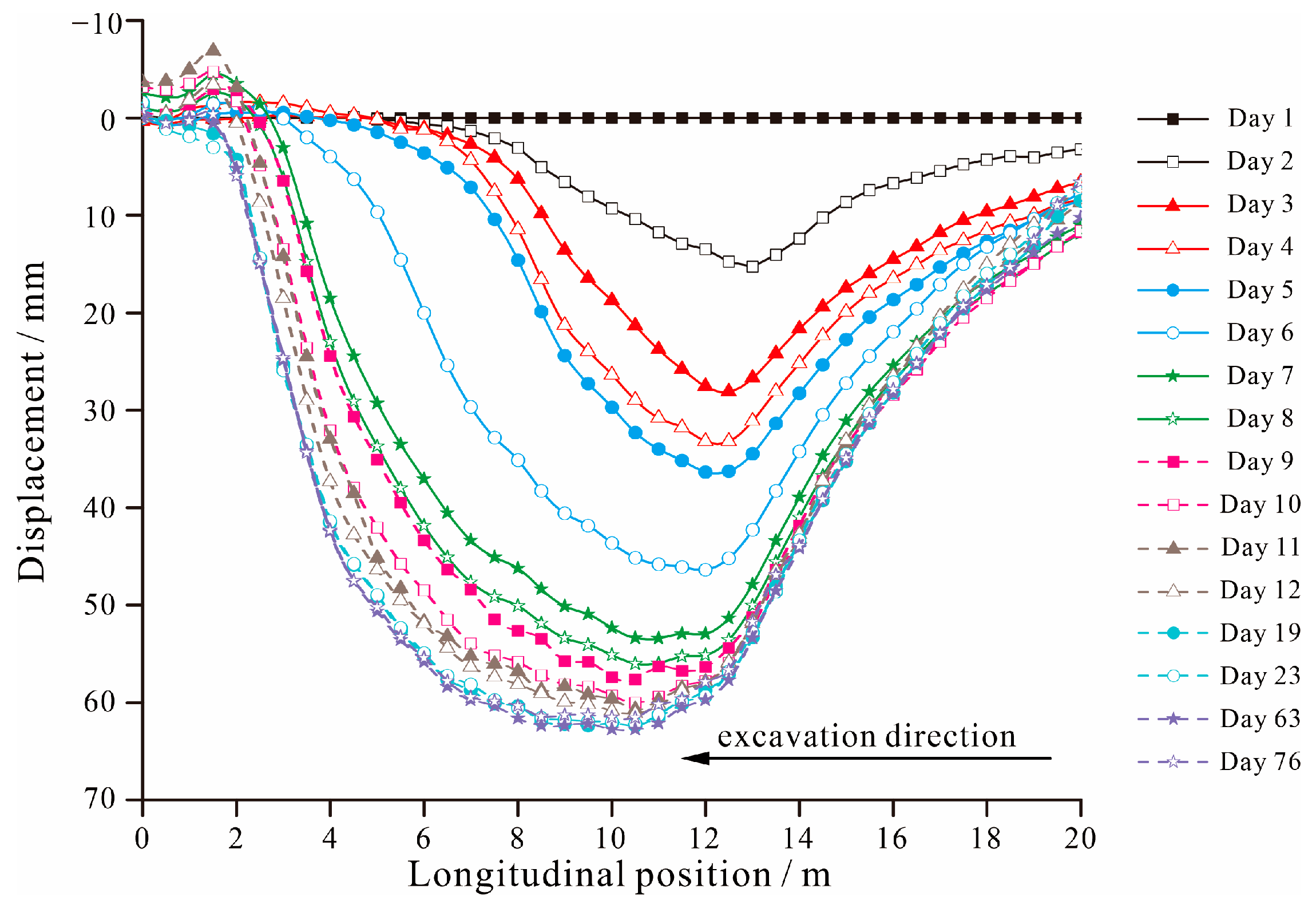
The longitudinal layout of the inclinometer casing is shown in Figure 12, and the time history curve of cumulative settlement of the pipe roof is illustrated in Figure 13.
As shown in Figure 13, the settlement of the pipe roof gradually increases with tunnel excavation. The deformation is pronounced initially but tends to stabilize after installing the initial support. In the depth range of 1 – 2 m, where the pipe roof is embedded within the portal arch, the vertical displacement values are negative, indicating slight upward deflection. This suggests the portal arch provides significant end restraint during tunnel exit excavation. It not only helps maintain slope stability but also effectively controls the overall settlement of the pipe roof.
The settlement curve of the pipe roof exhibits an overall “trough-shaped” distribution, which is smaller at both ends and larger in the middle. This is attributed to one end of the pipe roof being constrained by the portal arch and the other resting on the initial support. As the tunnel face advances toward the portal, settlement accumulates both spatially and temporally along the pipe roof.

5. Discussion on the Theoretical Solution

Hanjiashan Tunnel is set as the background project, which adopted the method of advanced support outside the tunnel. Based on the actual design parameters and excavation methods, the mechanical behavior of the pipe roof in different tunneling methods is studied by using Pasternak two-parameter foundation beam models.
Since the construction method adopted in Hanjiashan Tunnel involves installing the pipe roof from outside the tunnel, the Out–In ASA calculation model is used for comparison and validation. When the tunnel face is far from the tunnel exit, the boundary conditions of Model a are identical for both excavation approaches, resulting in the same calculation outcomes for both Out–In ASA and In–Out ASA calculation models. Therefore, the parameter sensitivity analysis is conducted for Model b under both Out–In ASA and In–Out ASA conditions.

5.1. Comparison and Validation with Measured Results

After completing the pipe roof installation, grouting is required to fill the rock voids and improve the physical and mechanical properties of the surrounding rock. At the same time, the slurry fills the interior of the steel pipe. Therefore, the modulus of the pipe roof in the calculation should consider the equivalent modulus after considering both the steel pipe and the grouting. According to the actual engineering situation, the outer diameter of the shed steel pipe is D = 0.127 m, the inner diameter is d = 0.118 m, and the moment of inertia of the steel pipe is I s = π ( D 4 d 4 ) 64 = 3.253 × 10 6   m 4 . The moment of inertia of the grout is I m = π d 4 64 = 9.517 × 10 6   m 4 . Taking the elastic modulus of the steel material as Es = 210 GPa and the elastic modulus of the grout as Em = 22 GPa, the equivalent elastic modulus of a single steel pipe is calculated as follows [4]:
E = E s I s + E m I m I s + I m = 69.89   GPa
Rock parameters are often obtained based on engineering analogies or inverse analysis methods [35]. However, the inverse analysis method involves a massive workload, and the reliability of the results is still a matter of debate. Therefore, this paper refers to values from literature [36] for rock parameters. Taking the foundation coefficient k = 40,000 kN/m3, foundation shear modulus Gp = 10,000 kN/m, unit weight γ = 20 kN/m3, and internal friction angle φ = 22°.
Due to the presence of the core soil at the tunnel face, taking the excavation height h = 2 m, the disturbance section in front of the tunnel face is d2 = 1.35 m. Analyzing and studying the pipe roof steel pipe located at the tunnel arch, the width of the soil acting on it is b = 0.4 m.
In summary, the calculation parameters for the support–surrounding rock system of the Hanjiashan Tunnel are listed in Table 1.
The results of Out–In ASA models and the field measurement data are compared.
(1)
Model a
As the tunnel face is far from the tunnel exit, the boundary conditions at both ends of the Model a are the same for the two tunneling methods. Therefore, only one calculation is required here.
When the distance from the tunnel face to the tunnel exit is 9 m, the depth of the tunnel face is 7 m. In this section, the vertical uniformly distributed pressure applied to the arch pipe roof at the top is q0 = 140 kPa. Every excavation cycle erects two steel arches, and their spacing is designed to be 0.5 m. Therefore, the length of the excavated unsupported section d1 is 1.2 m, and the calculation length is d1 + 9 m. Analysis of the monitoring data shows that the initial displacement of the pipe roof, i.e., the settlement at the arch crown at that location, ranges from 4.9 mm to 16.7 mm. Therefore, ω0 is taken as 10 mm. Since the distance from the tunnel face to the exit is relatively far, the initial rotation is θ0 = 1.5°.
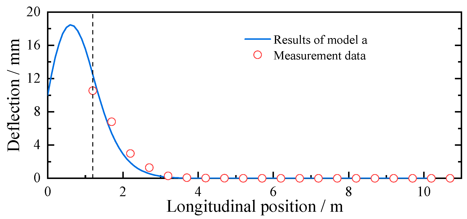
Based on the above parameters, the deflection curve of model a can be calculated as shown in Figure 14.
As shown in Figure 14, when the tunnel face is 9 m from the exit, the calculated deflection of the pipe roof at the tunnel face is 12.48 mm, while the measured value is 10.54 mm. The calculated value exceeds the measured one by 1.94 mm. This discrepancy is primarily due to the theoretical assumption that the surrounding soil behaves as a homogeneous and continuous elastic medium, which differs from actual ground conditions. Nevertheless, the maximum error between the calculated and measured values is 18.4%, which is within an acceptable range. Therefore, the results obtained from Model a show good agreement with the field measurement data.
At approximately 2.5 m from the tunnel face, the calculated deflection of the pipe roof approaches 0, which is consistent with the trend observed in the measurement data. The maximum pipe roof deflection occurs within the excavated unsupported section. The calculated peak deflection is 18.47 mm, which is attributed to the absence of initial support beneath the pipe roof in this zone. As a result, the full overburden pressure from the rock mass above acts directly on the pipe roof, leading to increased loading and greater deflection.
(2)
Model b
When the distance from the tunnel face to the exit is less than or equal to d2 = 1.35 m, the Model b is employed for the calculation.
The distance from the tunnel face to the exit is 1.35 m, and the tunnel face depth is 3 m. In this section, the vertical uniformly distributed pressure applied to the arch pipe roof at the top is q0 = 60 kPa. The length of the excavated unsupported section d1 is 1.2 m, and the calculation length is d1 + d2. The initial displacement ω0 = 10 mm. Since the distance to the exit is relatively close, the initial rotation is θ0 = 1°.
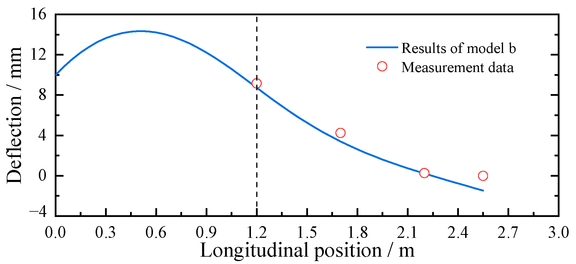
Based on the above parameters, the deflection curve of model b can be calculated as shown in Figure 15.
As shown in Figure 15, when the distance from the tunnel face to the exit is less than 1.35 m, the inclinometer reading at the tunnel exit is zero due to instrument damage at that location. However, the data from other monitoring points align well with the calculated results. The maximum deflection of the pipe roof is 14.36 mm, still occurring in the excavated unsupported section.
Due to the relatively thin overburden soil layer, the overall calculated deflection of Model b is smaller than that of Model a. As the pipe roof end is anchored to the portal arch, the deflection of the pipe roof at the portal is −1.46 mm, consistent with the cumulative settlement data shown in Figure 13. This validates the accuracy of the theoretical solution in Model b.
(3)
Error Analysis
Based on a comparison of Figure 14 and Figure 15, the maximum absolute error (MaxAE), maximum relative error (MaxRE), root mean square error (RMSE), mean absolute error (MAE), and coefficient of determination (R2) of the theoretical and measured results are calculated. The results are presented in Table 2.
The analysis of Table 2 indicates that both models can capture the overall variation trend of the pipe roof deflection well. The MaxRE is less than 20%, and R2 values greater than 0.94, indicating that the models exhibit reasonable engineering accuracy.
The results of Model a match closely with the field measurements. The theoretical model accurately predicts the key features, including the maximum deflection in the unsupported section and the deflection approaching zero at 2.5 m behind the tunnel face. The MaxAE occurs at the tunnel face, mainly because the theoretical model assumes the surrounding rock as a homogeneous and continuous elastic medium. In practice, the rock mass exhibits anisotropy, joints, and heterogeneity. Additionally, plastic deformation and stress-release effects reduce the actual load on the pipe roof compared to the theoretical prediction, leading to measured deflections at the tunnel face that are slightly smaller than the calculated values.
Model b also demonstrates good predictive capability. The slight upward movement at the pipe roof end in the theoretical calculation is consistent with the trend of cumulative settlement data, although the MaxAE appears at the tunnel portal. This might be due to the portal archer being unable to provide the fully fixed constraint assumed in the theoretical model.
In conclusion, the theoretical models exhibit good engineering accuracy when simulating the main load-bearing deformation segment of the pipe roof. However, simplifications in boundary condition modeling may be the primary cause of local discrepancies. Future studies will focus on parameterizing or refining the boundary conditions to reflect actual conditions better.

5.2. Parametric Sensitivity Analysis of Model b

Based on Table 1 and the computational data of Model b presented in Section 5.1 (2), a parameter sensitivity analysis is conducted for both the Out–In ASA and In–Out ASA cases. The analyzed parameters include the initial displacement ω0, initial rotation θ0, excavated unsupported section length d1, shear stiffness of the elastic foundation layer Gp, and foundation reaction coefficient k. Meanwhile, the present study [37,38] does not account for the 3D effects during tunnel construction, and most existing studies reduce 3D effects to an optimization problem of the overburden load acting on the pipe roof. The influence of the rock load q0 is studied.
A single-variable control method is employed, where only one parameter is discussed at a time. Furthermore, it should be noted that the ground parameters used in this study are not fixed values but can vary substantially in practical engineering conditions due to geological heterogeneity and construction disturbance. Barounis et al. [39,40] reported that k typically ranges from 3600~71,400 kN/m3 depending on soil type and reinforcement measures, and further suggested performing sensitivity analyses within the range of 0.5 k to 2.0 k. Therefore, based on field measurements and literature review, the parameter sensitivity analysis is conducted using k values of 20,000, 40,000, and 60,000 kN/m3. Similarly, Gp values of 5000, 10,000, and 20,000 kN/m are adopted.
The calculation results are shown in Figure 16. In the figure, blue lines represent the results for Out–In ASA, and red lines represent those for In–Out ASA. Different symbols indicate the calculation outcomes corresponding to the variation in each parameter.
As shown in Figure 16, although the deflection values vary across different parameter sets, the overall curve shapes remain similar. The calculated deflections for the In–Out ASA model are consistently higher than those for the Out–In ASA model. Meanwhile, the peak deflections are located closer to the tunnel face. As the portal arch’s fixed constraint is absent, the pipe roof acts as a free end, which increases both the load and the deflection.
From Figure 16a,b it can be seen that as the initial displacement increases from 10 mm to 30 mm, the maximum deflection values for both In–Out ASA and Out–In ASA scenarios increase by 126.1% and 109.9%, respectively, with the peak positions shifting backward from the tunnel face. When the initial rotation increases from 1° to 3°, the pipe roof deflections for both excavation methods also increase by 13.28 mm and 9.91 mm, corresponding to growth rates of 73.2% and 69.1%, respectively. The peak positions shift toward the tunnel face, with a larger position change observed in the In–Out ASA model. The result indicates that the In–Out ASA method lacks the portal arch’s constraints at the tunnel exit. The peak of deflection is more pronounced near the front of the tunnel face and more sensitive to the pipe roof’s initial displacement and rotation. Therefore, the timely installation of initial support and control of its early deformation are critical during tunnel portal construction to reduce pipe roof deflection.
Figure 16c shows that the deflection distribution pattern changes significantly as the excavation step length varies. Larger excavation steps result in longer unsupported lengths and greater peak deflections. The peak deflections for the In–Out model remain higher than those for the Out–In model and are located further behind the tunnel face. When d1 = 0.6 m, the difference in peak deflection is 15.3%; for d1 = 1.2 m, it is 26.5%; and for d1 = 1.8 m, it reaches 39.9%. This shows that structural deformation becomes more pronounced without the exterior fixed effect as the excavation step length increases.
Figure 16d,e show that the pipe roof deflection is inversely proportional to both the shear stiffness of the elastic foundation layer and the foundation reaction coefficient, following similar trends. Compared to other parameters, these two have a relatively minor effect on the deflection curves, mainly influencing the unexcavated section. This indicates that these two parameters primarily affect the overall support stiffness before excavation. Measures such as grouting can be employed to improve the surrounding rock conditions near the tunnel portal and control deformation after excavation.
Figure 16f indicates that the pipe roof deflection increases with the rock stress: as q0 increases from 30 to 120, the peak deflection rises from 13.83 to 15.54 mm (12.36%) for the Out–In ASA case and from 17.21 to 20.18 mm (17.26%) for the In–Out ASA case. According to previous research [37,38], both the arching effect between adjacent pipe roofs and the spatial effect induced by tunnel excavation can lead to variations in the rock stress. Since the pipe roof deformation strongly and positively correlates with the rock stress, its influence cannot be neglected. Therefore, particular attention should be paid to the arching effect between pipe roofs and the spatial effect caused by tunnel excavation.

6. Conclusions

Based on the Hanjiashan Tunnel project, this study employed Pasternak two-parameter elastic foundation beam models to investigate the mechanical behavior of the pipe roof in two different tunnel construction methods. The main conclusions obtained are as follows:
(1)
The corresponding boundary conditions for the In–Out ASA and Out–In ASA models are proposed based on the actual site conditions. Using the Pasternak two-parameter elastic foundation beam method, deflection calculation approaches for the pipe roof in both In–Out ASA and Out–In ASA models are established.
(2)
Field monitoring results indicate that the pipe roof settlement increases progressively with tunnel excavation but stabilizes after the installation of the initial support. Slight upward deflection near the embedded portal arch suggests strong end restraint, contributing to slope stability and overall deformation control. The settlement profile is “trough-shaped,” with minimal displacement at both ends and a maximum near the center, reflecting cumulative effects of excavation-induced loading and boundary conditions. Meanwhile, the Pasternak elastic foundation beam model proposed in this study fits the measured data well, with a maximum error not exceeding 18.4%, validating the rationality of the theoretical solution presented.
(3)
The results of the parameter sensitivity analysis indicate that the pipe roof deflection curves for both excavation methods are positively correlated with the initial displacement and rotation, as well as the length of the excavated unsupported section, and negatively correlated with the shear stiffness of the elastic foundation layer and the subgrade reaction coefficient. When the tunnel face is far from the exit, there is little difference between the two excavation methods. However, when the tunnel face is within the excavation disturbance range near the exit, the deflection of the In–Out ASA method is greater than that of the Out–In ASA, and the peak deflection is closer to the tunnel face. This is because the anchoring effect of the portal arch at the exit is absent, causing the pipe roof to be treated as a free end at the exit, which increases the load and the deflection. In addition, the deflection of the pipe roof shows a significant positive correlation with the rock stress. Therefore, when construction conditions at the tunnel exit are met, the Out–In ASA method is recommended. If conditions for advanced support outside the tunnel are lacking, the In–Out ASA method can be used. However, it is necessary to install initial support promptly, reasonably design the excavation advance length, and ensure effective grouting under poor surrounding rock conditions to control pipe roof deformation.
(4)
The theoretical solution presented in this study is developed and validated under a set of reasonable assumptions. It can be further improved in the following aspects: (a) The treatment of boundary conditions could be further refined by incorporating rotational spring stiffness or partially restrained conditions, thereby providing a closer representation of realistic end restraints in practice. (b) The applicability of the model may be enhanced by considering 3D effects and the arching interaction between pipe roofs, supported by numerical simulations and field monitoring, to better assess the influence of complex boundary conditions and spatial coupling on the mechanical response.

Author Contributions

Conceptualization, Y.L.; Methodology, B.G.; Software, C.W. and X.Q.; Formal analysis, B.G., C.W. and M.W.; Investigation, B.G.; Resources, Y.L. and J.C.; Data curation, C.W.; Writing—original draft, Y.L., B.G. and M.W.; Writing—review & editing, J.C.; Visualization, X.Q.; Supervision, Y.L. and J.C. All authors have read and agreed to the published version of the manuscript.

Funding

This research was funded by the Natural Science Foundation of China (52278394) and Natural Science Foundation of China (52178380), supported by the Program for Innovation Capacity in University of Shaanxi Province, China (2024RS-CXTD-42). And The APC was funded by the Fundamental Research Funds for the Central Universities of Ministry of Education of China (300102213402).

Data Availability Statement

Data are contained within the article.

Acknowledgments

We extend our sincere appreciation to each co-author for their dedicated work and input throughout the study.

Conflicts of Interest

The authors declare that they have no known competing financial interests or personal relationships that could have appeared to influence the work reported in this paper.

References

  1. Guan, B.S. Deformation of tunnels with soft surrounding rocks and its control. Tunnel Constr. 2011, 31, 1–17. [Google Scholar]
  2. Tao, K.; Li, X.L.; Shi, H.L. Construction technology and quality control of big-long pipe-roof in shallowly buried section of tunnel. Road Mach. Constr. Mech. 2010, 27, 65–69. [Google Scholar]
  3. Gou, D.M.; Yang, J.S.; Zhang, G. Deformation monitoring and mechanical behaviors of pipe-roof in shallow tunnels. Chin. J. Rock Mech. Eng. 2007, 26, 1258–1264. [Google Scholar]
  4. Wang, H.T.; Jia, J.Q.; Yu, S. Mechanical behavior and parameter optimization of pipe roof reinforcement applied in tunnel. China J. Highw. Trans. 2010, 23, 78–83. [Google Scholar]
  5. Zheng, J.J.; Zhang, R.J.; Yang, Q.N. Mechanical mechanism of pipe roofs with variable coefficient of subgrade reaction in shallow tunnels. Chin. J. Geotech. Eng. 2009, 31, 1165–1171. [Google Scholar]
  6. Jia, J.Q.; Wang, H.T.; Tu, B.X.; Meng, G. Analytical approach and field monitoring for mechanical behaviors of pipe roof reinforcement. Rock Soil Mech. 2010, 31, 1858–1864. [Google Scholar]
  7. Li, J.; Tan, Z.S.; Yu, Y.; Ni, L.S. Analysis of deformation monitoring and mechanical behaviors of big pipe-roof for shallow-buried large-span tunnel to underpass highway. Chin. J. Rock Mech. Eng. 2011, 30, 3002–3008. [Google Scholar]
  8. Dong, X.P.; Zhou, S.H.; Hu, X.P. 3D analysis of function of pipe roof applied in soft ground. Chin. J. Geotech. Eng. 2006, 28, 841–846. [Google Scholar]
  9. Guenther, M.V.; Wulf, S. Optimization of excavation and support in pipe roof supported tunnel sections. Tunn. Undergr. Space Technol. 2006, 21, 404. [Google Scholar] [CrossRef]
  10. Hefny, A.M.; Tan, W.L.; Pathegama, R.G.; Sharma, J.; Zhao, J. Numerical analysis for umbrella arch method in shallow large scale excavation in weak rocks. Tunn. Undergr. Space Technol. 2004, 19, 1–7. [Google Scholar] [CrossRef]
  11. Shi, Y.F.; Cai, L.P.; Yang, J.S.; Hu, W.T. Combination reinforcement mechanism of sub-horizontal jet-grouting and pipe roof in water-rich soft stratum. Chin. J. Geotech. Eng. 2015, 37, 101–106. [Google Scholar]
  12. Yang, Z.F. Study on mechanical characteristics of tunnel entrance reinforced with pipe roof in deep accumulation. Road Mach. Constr. Mech. 2017, 34, 100–103. [Google Scholar]
  13. Yoo, C.; Shin, H.Y. Deformation behavior of tunnel face reinforced with longitudinal pipes-laboratory and numerical investigation. Tunn. Undergr. Space Technol. 2003, 18, 303–319. [Google Scholar] [CrossRef]
  14. Hisatake, M.; Ohno, S. Effects of pipe roof supports and the excavation method on the displacements above a tunnel face. Tunn. Undergr. Space Technol. 2008, 23, 120–127. [Google Scholar] [CrossRef]
  15. Shin, J.H.; Choi, Y.K.; Kwon, O.Y. Model testing for pipe-reinforced tunnel heading in a granular soil. Tunn. Undergr. Space Technol. 2008, 23, 241–250. [Google Scholar] [CrossRef]
  16. Zhou, S.H. Principles of pipe roof applied to shallow-buried tunnels in soft ground. Chin. J. Rock Mech. Eng. 2005, 24, 2565–2570. [Google Scholar]
  17. Bai, Q.; Zhao, W.; Sun, Y.; Wang, X. Pipe Curtain Deformation and Surface Subsidence Caused via Excavation of Transverse Pilot Tunnel under Pipe Curtain Support. Sustainability 2023, 15, 11967. [Google Scholar] [CrossRef]
  18. Chen, S.L.; Chang, S.W.; Qiu, Z.Y.; Tang, C.W.; Zhang, X.L.; Chen, Y. Numerical Model for Rectangular Pedestrian Underpass Excavations with Pipe Roof Preconstruction Method: A Case Study. Appl. Sci. 2023, 13, 5952. [Google Scholar] [CrossRef]
  19. Jia, P.J.; Zhao, W.; Du, X.; Chen, Y.; Zhang, C.Z.; Bai, Q.; Wang, Z.G. Study on ground settlement and structural deformation for large span subway station using a new pre-supporting system. R. Soc. Open Sci. 2019, 6, 6181035. [Google Scholar] [CrossRef]
  20. Jia, P.J.; Zhao, W.; Khoshghalb, A.; Ni, P.P.; Jiang, B.F.; Yang Chen, Y.; Li, S.G. A new model to predict ground surface settlement induced by jacked pipes with flanges. Tunn. Undergr. Space Technol. 2020, 98, 103330. [Google Scholar] [CrossRef]
  21. Wang, J.; Li, X.; Wu, S.Z.; He, Z.W.; Wei, Y. Field test and numerical simulation of ground settlement in super shallow buried station excavation supported by transverse pipe roof. Front. Earth Sci. 2023, 11, 1136270. [Google Scholar] [CrossRef]
  22. Lu, B.; Dong, J.C.; Zhao, W.; Du, X.; Cheng, C.; Bai, Q.; Wang, Z.G.; Zhao, N.C.; Han, J.Y. Novel pipe-roof method for a super shallow buried and large-span metro underground station, Undergr. Space 2022, 7, 134–150. [Google Scholar]
  23. Li, Z.; Yue, X.; Wu, G. Calculation and Analysis of Pipe Joint Settlement Control in Large Back Silting Immersed Tube Tunnel. Sustainability 2023, 15, 7446. [Google Scholar] [CrossRef]
  24. Chen, L.J.; Zhang, Y.L. Double parameters elastic foundation beam model of feet-lock pipes. Chin. J. Rock Mech. Eng. 2016, 35, 989–999. [Google Scholar]
  25. Fu, D.X.; Deng, B.; Yang, M.H.; Zhen, B.B. Analytical solution of overlying pipe deformation caused by tunnel excavation based on Pasternak foundation model. Sci. Rep. 2023, 13, 921. [Google Scholar] [CrossRef] [PubMed]
  26. Chen, S.S.; Kao, C.J.; Shi, J.Y. Dynamic analysis of cylindrical foundations under torsional loading via generic discrete-element models simulating soil stratum. Sci. Rep. 2023, 13, 19163. [Google Scholar] [CrossRef] [PubMed]
  27. Yang, T.; Deng, B.; Yang, M.; Fu, D.X. A new approach for evaluating continuous and discontinuous pipeline deformation induced by soil tunnel excavation. Sci. Rep. 2023, 13, 12661. [Google Scholar] [CrossRef]
  28. Wu, Y.H.; Xiao, C.J.; Chen, F.Q.; Cai, G. Study on mechanical characteristics of pipe umbrella support in shallow buried tunnels. Tunn. Undergr. Space Technol. 2024, 145, 105578. [Google Scholar] [CrossRef]
  29. Luo, Y.B.; Chen, J.X.; Liu, B.; Chen, L.J.; Xie, J.T. Analysis of Pipe-Roof in Tunnel Exiting Portal by the Foundation Elastic Model. Math. Probl. Eng. 2017, 7, 1–12. [Google Scholar] [CrossRef]
  30. Jiang, X.; Zhang, X.H.; Zhang, X.; Long, L.Y.; Bai, Y.; Huang, B.S. Advancing Shallow Tunnel Construction in Soft Ground: The Pipe-Umbrella Box Jacking Method. Transport. Res. Rec. 2024, 2678, 150–168. [Google Scholar] [CrossRef]
  31. Wang, H.; Qin, W.M.; Jiao, Y.Y. Stability assessment for highway with large span box culvert jacking underneath: A case study. Can. Geotech. J. 2013, 50, 585–594. [Google Scholar] [CrossRef]
  32. Li, R.; Zhang, D.L.; Wu, P.; Fang, Q.; Li, A.; Cao, L.Q. Combined Application of Pipe Roof Pre-SUPPORT and Curtain Grouting Pre-Reinforcement in Closely Spaced Large Span Triple Tunnels. Appl. Sci. 2020, 10, 3186. [Google Scholar] [CrossRef]
  33. JTG D70-2004; Specifications for Design of Highway Tunnels. China Communications Press: Beijing, China, 2004.
  34. Luo, Y.B.; Chen, J.X.; Huang, P.; Tang, M.Q.; Qiao, X.; Liu, Q. Deformation and mechanical model of temporary support sidewall in tunnel cutting partial section. Tunn. Undergr. Space Technol. 2017, 61, 40–49. [Google Scholar] [CrossRef]
  35. Luo, Y.B.; Chen, J.X.; Chen, Y.; Diao, P.S.; Qiao, X. Longitudinal deformation profile of a tunnel in weak rock mass by using the back analysis method. Tunn. Undergr. Space Technol. 2018, 71, 478–493. [Google Scholar] [CrossRef]
  36. Hu, B. Research on Advance Supporting Effect of Pipe Roof of Dingjiashan Tunnel in Soft and Crumble Surrounding Rocks. Master’s Thesis, Huazhong University of Science & Technology, Wuhan, China, 2011. [Google Scholar]
  37. Chen, C.N.; Huang, W.Y.; Tseng, C.T. Stress redistribution and ground arch development during tunneling. Tunn. Undergr. Space Technol. 2011, 26, 228–235. [Google Scholar] [CrossRef]
  38. Rong, Y.; Du, W.; Sun, Y.; Xiong, F.; Liu, L.; Yu, S.; Jie, G. Study on Stress Deformation of Pipe Shed in Shallow Buried Tunnel Considering Micro-Arch Effect. Adv. Civ. Eng. 2024, 2024, 6651993. [Google Scholar] [CrossRef]
  39. Barounis, N.; Philpot, J. Estimation of the static vertical subgrade reaction modulus ks from CPT for shallow foundations on cohesionless soils. SESOC J. 2017, 30, 58–63. [Google Scholar]
  40. Barounis, N.; Philpot, J. Estimation of the static vertical subgrade reaction modulus ks from CPT. In Cone Penetration Testing 2018, Proceedings of the 4th International Symposium on Cone Penetration Testing (CPT'18), Delft, The Netherlands, 21–22 June 2018; CRC Press: Boca Raton, FL, USA, 2018; pp. 123–128. [Google Scholar]
Figure 1. The field situation of Out–In ASA.
Buildings 15 03221 g001
Figure 2. The field situation of In–Out ASA.
Buildings 15 03221 g002
Figure 3. Force of the pipe roof during tunnel excavation.
Buildings 15 03221 g003
Figure 4. Transversal load on the pipe roof.
Buildings 15 03221 g004
Figure 5. Mechanical model of the pipe roof in the tunnel construction process at the exit portal [29].
Buildings 15 03221 g005
Figure 6. Mechanical Model of a Pipe Roof micro-section.
Buildings 15 03221 g006
Figure 7. The original ground surface at the tunnel entrance.
Buildings 15 03221 g007
Figure 8. The geological conditions of the surrounding rock at the tunnel entrance on the left line.
Buildings 15 03221 g008
Figure 9. Cross-section of advanced support at the left-line tunnel entrance.
Buildings 15 03221 g009
Figure 10. Construction of advanced support at the left-line tunnel entrance.
Buildings 15 03221 g010
Figure 11. The lining structure at the left-line tunnel entrance.
Buildings 15 03221 g011
Figure 12. Layout Method of Inclinometer Pipes at Monitoring Cross-Sections.
Buildings 15 03221 g012
Figure 13. The time history curve of cumulative settlement of the pipe roof.
Buildings 15 03221 g013
Figure 14. Comparison between the results of model a and the measurement data.
Buildings 15 03221 g014
Figure 15. Comparison between the results of model b and the measurement data.
Buildings 15 03221 g015
Figure 16. Parametric Sensitivity Analysis of Model b.
Buildings 15 03221 g016aBuildings 15 03221 g016b
Table 1. Calculation parameters for the Hanjiashan Tunnel.
EIkGpd2bγφ
GPam4kN/m3kN/mmmkN/m3°
69.8912.7740,00010,0001.350.42022
Table 2. Error Analysis of Model a and Model b.
MaxAEMaxRERMSEMAER2
Model a1.939−18.4%0.5950.2570.949
Model b1.45919.8%0.8710.6920.945
Disclaimer/Publisher’s Note: The statements, opinions and data contained in all publications are solely those of the individual author(s) and contributor(s) and not of MDPI and/or the editor(s). MDPI and/or the editor(s) disclaim responsibility for any injury to people or property resulting from any ideas, methods, instructions or products referred to in the content.