Article

Investigation of Borehole Network Parameters for Rock Breaking via High-Pressure Gas Expansion in Subway Safety Passages of Environmentally Sensitive Zones

School of Resources and Safety Engineering, Central South University, Changsha 410083, China
*
Author to whom correspondence should be addressed.
Buildings 2025, 15(17), 3158; https://doi.org/10.3390/buildings15173158
Submission received: 8 August 2025 / Revised: 29 August 2025 / Accepted: 31 August 2025 / Published: 2 September 2025
(This article belongs to the Section Building Structures)

Abstract

To address the challenge of determining the borehole layout scheme in the practical application of high-pressure gas expansion rock breaking, this study takes the excavation of the safety passage at Kaixuan Road Station on the North Extension Line 2 of Chongqing Metro Line 18 as the engineering background. The rock-breaking capacity was evaluated by analyzing the damaged zone volume caused by gas expansion using FLAC3D 6.0 numerical simulation software, and vibration monitoring was conducted for the historical buildings on the surface. This study revealed the following: (1) When the borehole depth is 1.2 m and the charge length is 0.6 m, the optimal angle is 70°, with the optimal vertical and horizontal spacing between holes being 1200 mm and 2000 mm, respectively. (2) The numerical simulations indicated that by adjusting the charge density, the optimized sandstone borehole network parameters could be applied to mudstone strata, and the rock-breaking effect was similar. The difference in the volume of the damaged zones obtained in the two strata was less than 3%. (3) The vibration analysis demonstrated that the peak particle velocity generated by high-pressure gas expansion rock fracturing at the ancient building directly above was 0.06316 cm/s, which was lower than the threshold value of 0.1 cm/s and approximately 67.95% lower than that of explosive blasting. Furthermore, when the tunnel depth exceeded 29 m, the vibration velocity of surface structures remained within the safety range. The results verified the feasibility of applying the same borehole network parameters to different strata, providing theoretical support for the practical application of high-pressure gas expansion rock fracturing technology in engineering projects.

1. Introduction

With the development and progress of society, urban underground transportation, urban underground transportation networks have become increasingly developed. In the process of developing new lines and expanding old ones, it is inevitable to pass through or be adjacent to historical sites, municipal pipelines, and core urban buildings, which results in higher requirements for engineering construction. Therefore, identifying how to maintain operational efficiency while meeting stricter standards during underground tunnel excavation has become a major issue in modern tunnel engineering research. Non-blasting rock methods have significant advantages over drilling and blasting techniques in certain aspects and are typically used as alternative or auxiliary rock-breaking methods. In recent years, many scholars have conducted research in this field and have identified a series of non-blasting rock-breaking techniques, such as water jet cutting [1,2,3,4,5], laser rock breaking [6,7,8,9], CO2 phase change fracturing [10,11,12,13], liquid nitrogen jet fracturing [14,15,16,17], and particle shock wave rock breaking [18,19,20,21]. Among these, the CO2 phase change fracturing method is similar to the high-pressure gas expansion rock-breaking technique investigated in this study, as both utilize gas pressure to fracture the rock. The difference lies in the phase transition mechanism: CO2 phase change fracturing involves the transformation of liquid CO2 into gas, whereas high-pressure gas expansion rock breaking involves the conversion of solid gas-generating agents into gas. At present, the CO2 phase change fracturing technique faces challenges such as complex equipment and high costs; a complete system can cost several hundred thousand RMB, and when combined with the expenses related to the transportation and storage of liquid CO2, the overall cost approaches or even exceeds that of conventional explosive blasting. In comparison, the high-pressure gas expansion rock-breaking technology studied in this paper offers advantages such as lower cost, simpler operation, and more convenient transportation. Wei et al. [22] investigated the propagation characteristics of stress waves in layered rock masses under the impact of high-pressure gas through numerical simulations, which provided theoretical guidance and practical value for optimizing rock fragmentation methods. Peng et al. [23] conducted field tests in hard rock tunnels and fitted two velocity prediction formulas, which were further validated by numerical simulations. The results indicated that high-pressure gas expansion fracturing had significant advantages and could serve as a substitute for explosives in special areas. Liu et al. [24] applied high-pressure gas expansion fracturing technology in small cross-section hard rock tunnels in urban settings and tested three different borehole network parameters. It was found that with a reasonable arrangement of cut holes and empty holes, low disturbance could be maintained while achieving effective rock fragmentation. This technique was further applied to tunnel face excavation, and comparative analysis with the conventional drilling and blasting method demonstrated that the vibration caused by high-pressure gas expansion fracturing was lower, further confirming the feasibility of this technology. In order to address the problem of severe vibration associated with the traditional drilling and blasting method, Peng et al. [25] conducted field tests of high-pressure gas expansion fracturing in hard rock tunnels and demonstrated that the vibration velocity generated was lower than that produced by explosive blasting under the same conditions.
Most existing studies have been conducted in hard rock and within single-stratum environments, without considering more complex surrounding rock conditions. The Chongqing Metro Line 18 North Extension Project crosses both sandstone and mudstone strata with different strengths, and the excavation of the KaiXuan Station safety passage was taken as the engineering background in this study. Numerical simulations were carried out to investigate the rock-breaking performance of sandstone under different borehole network parameters, and the most suitable drilling parameters were identified. To enhance the control effect of rock fracturing, the same borehole arrangement parameters were applied to both strata. During charging, adjustments were made according to drilling parameters or the morphology of the tunnel face. Therefore, in this study, sandstone was selected as the reference stratum, and numerical simulations were conducted to extend the optimized borehole network parameters to mudstone. By comparing the damaged zone volumes of both strata under identical working conditions, it was demonstrated that the same set of borehole parameters could be applied to both sandstone and mudstone by adjusting the charge density, with the potential to extend this approach to additional strata. Meanwhile, vibration monitoring was conducted to ensure the safety of the historical building “Xie’s Residence”. The findings provide theoretical support for the engineering application of high-pressure gas expansion rock-fracturing technology in both sandstone and mudstone formations.

2. Principles and Feasibility of High-Pressure Gas Expansion Rock-Fracturing Technology

2.1. Rock-Fracturing Equipment and Process

In engineering practice, the main equipment for high-pressure gas expansion rock breaking is the expansion tube, whose shell is a PVC pipe of a certain length, filled with a gas-generating agent and an ignition head inside. It can be used once sealed. Figure 1 shows the structural diagram and physical image of the expansion tube.
As shown in Figure 2, after the preparatory work, such as the installation of the expansion tubes, was completed, drilling was carried out according to the design scheme, and the expansion tubes were placed in the boreholes, generally ensuring that they were in contact with the borehole bottom. Once the installation was completed, quick-setting cement was used as the sealing material to close the borehole collar. Finally, the expansion tubes to be detonated were connected with lead wires, which were then attached to the detonator, and initiation was carried out using the detonator. Among them, sealing the hole is a critical step in rock breaking, as the quality of the sealing directly impacts the rock-breaking effect. If there are gaps in the seal or if punching occurs during the reaction, the high-pressure gas generated by the gas-generating agent will leak, leading to a decrease in the peak pressure exerted on the hole wall, thus preventing the desired rock-breaking effect from being achieved.
Theoretically, under standard conditions, 1 kg of gas-generating agent can produce 626.16 L of high-pressure, high-temperature gas, with a peak pressure reaching several hundred megapascals. Since the chemical reaction process of the gas-generating agent is typically completed in an extremely short time (on the millisecond scale), the gas generation rate is much higher than the physical expansion rate of the rock-breaking device (i.e., the expansion tube). Before the reaction is completed, the system volume cannot change immediately due to the rigid structure of the rock-breaking device, so the gas generation process of the agent can be regarded as a constant volume reaction process. The peak pressure of the high-temperature, high-pressure gas generated by the gas-generating agent reaction inside the expansion tube can be calculated using the Van der Waals equation of state:
P = n V 0 V a R T = ρ n R T 1 V a ρ 127.6   M P a
where P denotes the peak pressure of the high-temperature and high-pressure gas generated by the reaction; ρ represents the charge density; V a represents the residual volume of the gaseous products generated from the reaction of the gas-generating agent, which is taken as 0.0005 m3/kg in this study; according to the ideal gas law, the relationship is expressed as n R T = P 0 V 0 T T 0 ; T is the reaction temperature of the gas-generating agent; P 0 is the standard atmospheric pressure; T 0 is the standard temperature; and V 0 is the volume of gas generated by the gas-generating agent under standard conditions.
Based on Equation (1), the reaction parameters of the gas-generating agents used in the four types of expansion tubes in this study are shown in Table 1.
It should be noted that the charge density directly determines the volume of gas generated by the gas-generating agent. In the confined space of the expansion tube, the greater the total amount of gas produced per unit time, the higher the peak pressure formed. Therefore, for expansion tubes requiring different peak pressures under varying conditions, adjustment can be achieved simply by increasing or decreasing the mass of the gas-generating agent inside the tube to modify the charge density. However, it should also be emphasized that in practical applications, an excessively high charge density may lead to incomplete combustion due to an insufficient supply of oxidants, which can result in a peak pressure lower than that obtained with a smaller charge density.

2.2. Theoretical Analysis of High-Pressure Gas Expansion Rock Fracturing

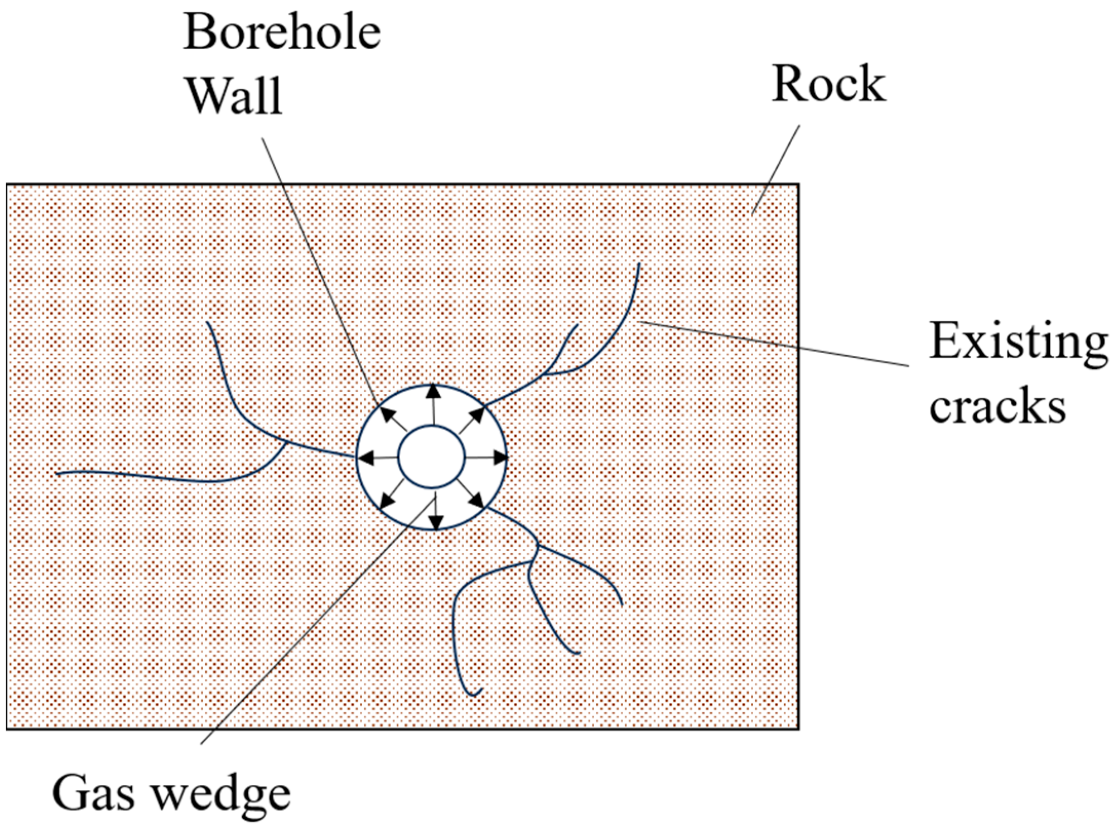
Existing studies have shown that two distinct forms of loading occur under explosive blasting, namely, the dynamic effect of explosion-induced stress waves and the quasi-static effect of high-pressure detonation gases, both of which cause varying degrees of damage to the rock mass. Although these two processes occur in sequence over time, they are interrelated and complex, making it difficult to separate them entirely. In smooth blasting or pre-splitting blasting, the use of decoupled charge structures significantly weakens the effect of shock waves, yet effective rock fragmentation at the tunnel face can still be achieved. This indicates that the damage caused by the quasi-static action of detonation gases on rock cannot be neglected. As shown in Figure 3, within the expansion tube, the gas-generating agent is ignited by the ignition head and decomposes to produce a large volume of high-temperature gas. When the internal gas pressure reaches the threshold, the expansion tube ruptures, and the high-temperature and high-pressure gas triggers the gas wedge effect, namely, the penetration of high-pressure gas into the inherent fissures of the rock, which drives the rock to fail along these fissures. From the perspective of action duration, the high-temperature and high-pressure gas acts on the borehole wall for a relatively long period, causing the rock fractures to propagate continuously until macroscopic cracks are formed at the tunnel face or in the cut. Subsequently, the fractured rock mass is ejected outward under the pressure of the high-pressure gas, thereby achieving the rock-breaking effect [26,27,28].

2.3. Feasibility Analysis

In the practice of high-pressure gas expansion rock breaking, under otherwise identical conditions, a more fully developed free surface tends to result in improved rock-breaking performance due to the presence of the gas wedge effect.
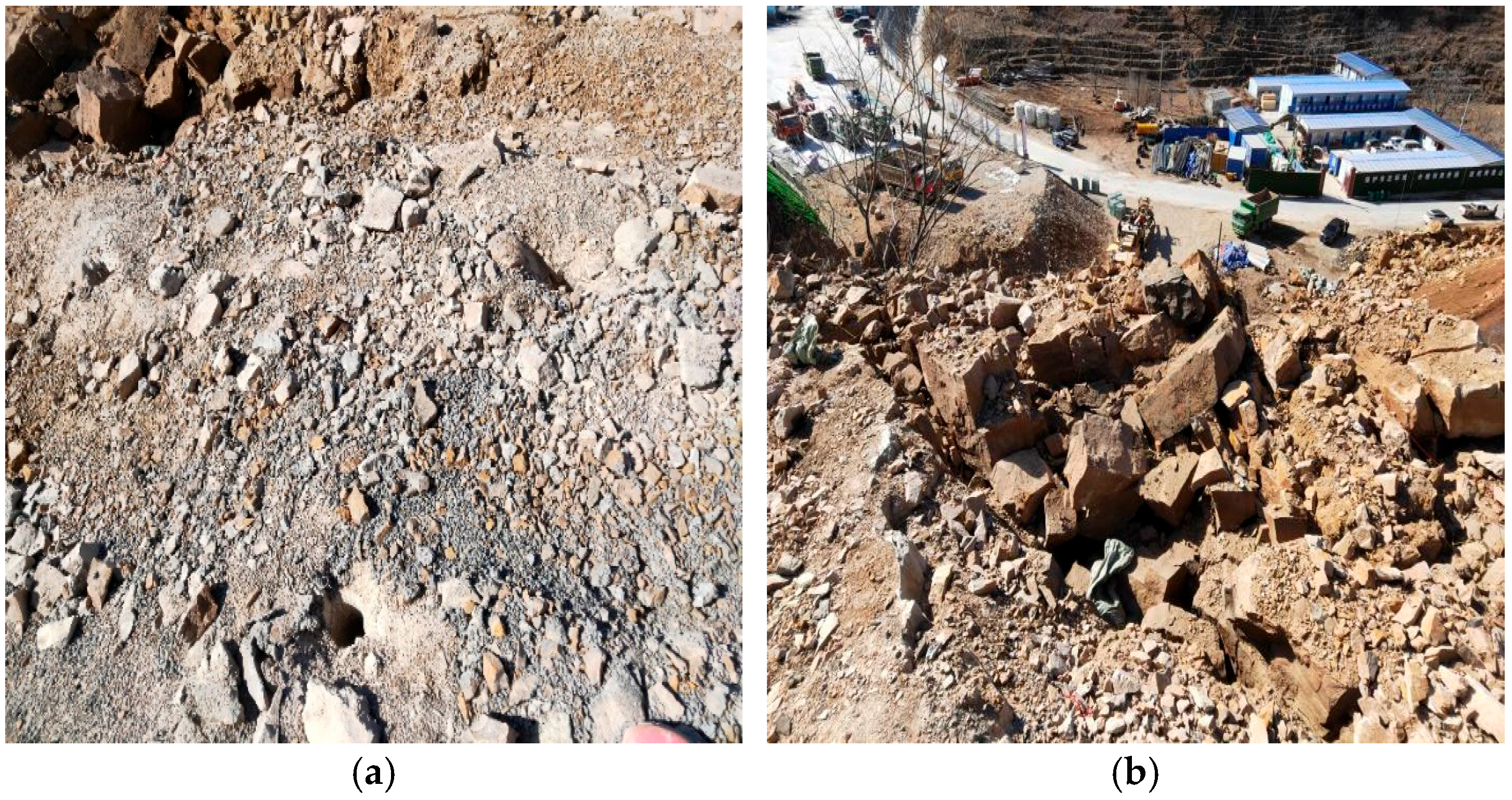
Table 2 presents the mechanical parameters of the rock mass in the test area. In the experiment shown in Figure 4, multiple expansion tubes were arranged longitudinally at intervals along the vertical direction of the slope, with the closest distance to the slope edge being 1 m and a spacing of 1 m between the tubes. After rock fragmentation was completed, the rock mass was ejected outward, and a satisfactory rock-breaking effect was achieved. Therefore, in the engineering practice of high-pressure gas expansion rock breaking, the creation of a free surface through mechanical excavation or delayed detonation of pilot holes can enable subsequent expansion tubes to achieve better performance, thereby maximizing the advantages of the high-pressure gas expansion rock-breaking technique.

3. Finite Element Analysis

At present, although high-pressure gas expansion rock breaking has been partially applied in tunnel excavation projects, parameters such as borehole layout and charge density are still largely determined based on the designer’s experience. On the one hand, this situation tends to result in increasingly conservative parameter selection during communication among practitioners, thereby increasing rock-breaking loss and overall cost. On the other hand, the high cost of trial-and-error methods in actual engineering may lead to rock-breaking effects that significantly deviate from expected targets, causing unpredictable losses in manpower, materials, and time. Therefore, prior to actual engineering implementation, finite element analysis should be conducted using FLAC3D 6.0 numerical simulation software to investigate parameters such as borehole layout and charge density, so as to select the optimal configuration and enhance the rationality and efficiency of high-pressure gas expansion rock breaking in practical applications.

3.1. Model Parameters

3.1.1. Geological Parameters

Based on the field geological survey data, the selected parameters for the numerical simulation were determined, as shown in Table 3. In the numerical simulation, the rock mass was modeled using the Mohr–Coulomb constitutive model, while the wooden structure of the Xiejia Courtyard area was simulated using an elastic constitutive model.

3.1.2. Expansion Tube Action Parameters

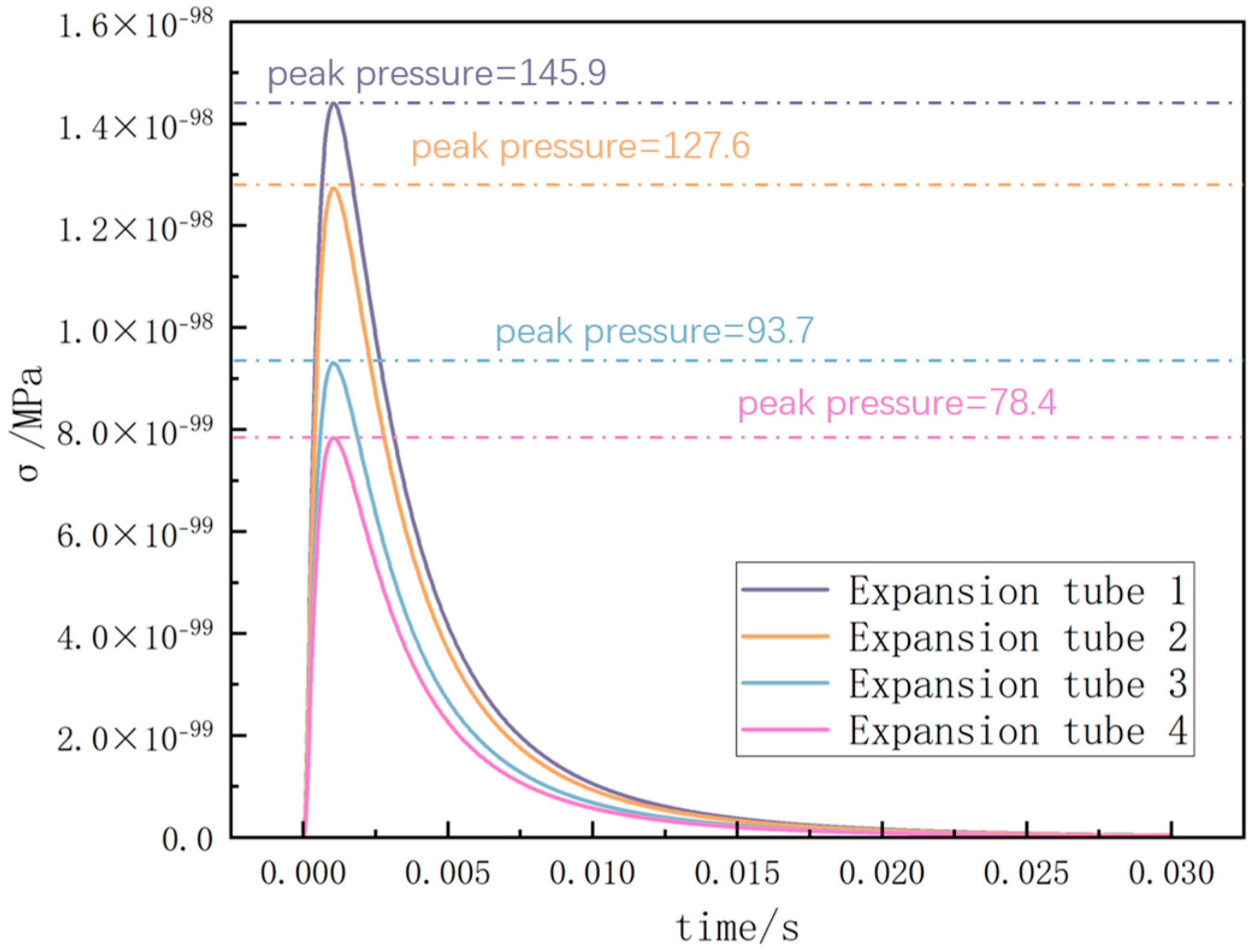
After the ignition head is triggered, the high-pressure gas rapidly expands within the rock-breaking device, and its dynamic action process conforms to the typical characteristics of “shock depressurization”. Specifically, the gas pressure rapidly rises to its peak within an extremely short period of time and subsequently enters the depressurization phase, during which the pressure gradually decreases to a minimum value over a relatively longer duration compared to the rising phase. In the preceding section, the peak pressures of expansion tubes 1, 2, 3, and 4 were calculated using the Albert residual volume equation, and the corresponding high-pressure gas load curves are shown in Figure 5.
According to previous studies [29,30,31], the duration of the entire process from pressure rise to decline during high-pressure gas expansion rock fracturing is approximately 20 ms. Therefore, in FLAC3D 6.0, the above loading curve was applied to the borehole wall region of the corresponding fracturing holes to simulate the gas wedge effect during the high-pressure gas expansion process. In practical applications, the severity of jetting is difficult to quantify, and its occurrence probability is relatively low when key parameters such as borehole angle and charge density are carefully designed. Hence, in the numerical simulations, it was assumed that jetting does not occur, and the pressure was considered to act entirely on rock fracturing, allowing the borehole pressure to reach the peak value shown in Figure 5.

3.2. Study on Borehole Network Parameters in the Cut Area

As a key element in tunnel blasting design, the rationality of the slot hole design directly affects the blasting energy transfer efficiency, rock fragmentation degree, and the formation accuracy of the excavation contour line. Its network parameters generally include three-dimensional dimensions: the angle α between the slot hole and the face, the vertical spacing H, and the horizontal spacing D between the holes. Currently, there is a lack of systematic research on the synergy of these three factors. Therefore, this study adopted the control variable progressive optimization method to iteratively optimize the slot hole parameters, using the damaged zone volume V d as the evaluation index.
Furthermore, to obtain a set of universal slot zone parameters suitable for both sandstone and mudstone strata, this study first optimized the combination of α, H, and D for the sandstone layer and then adjusted the explosive density to enable the mudstone layer to generate a damaged zone comparable to that of the sandstone. In this study, the region of the surrounding rock that undergoes tensile and shear failure after the completion of the high-pressure gas expansion rock fracturing process was defined as the damage zone, and the volume of this region was referred to as the damage zone volume V d .

3.2.1. Research on the Optimization of Hole Angle Spacing

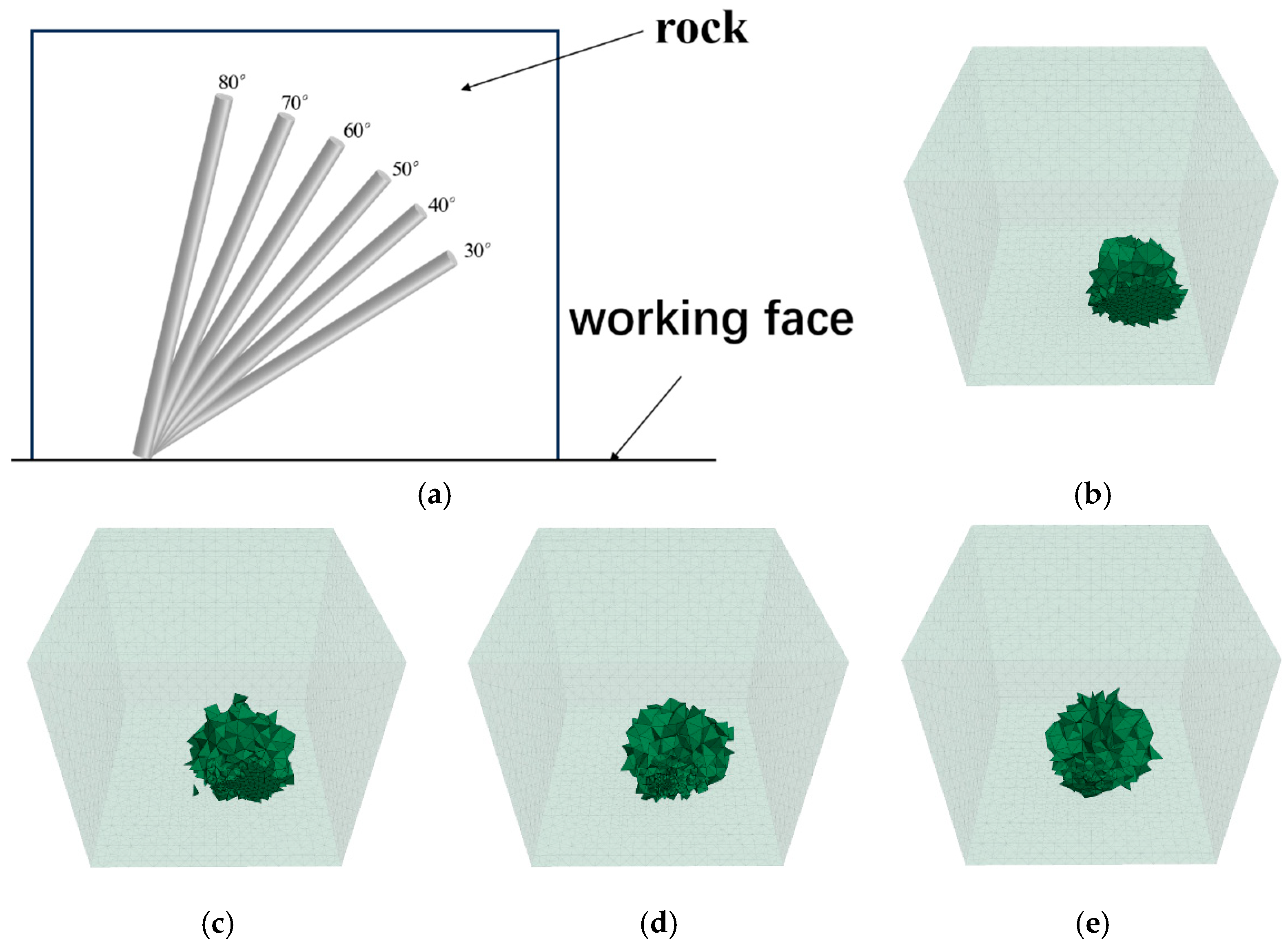
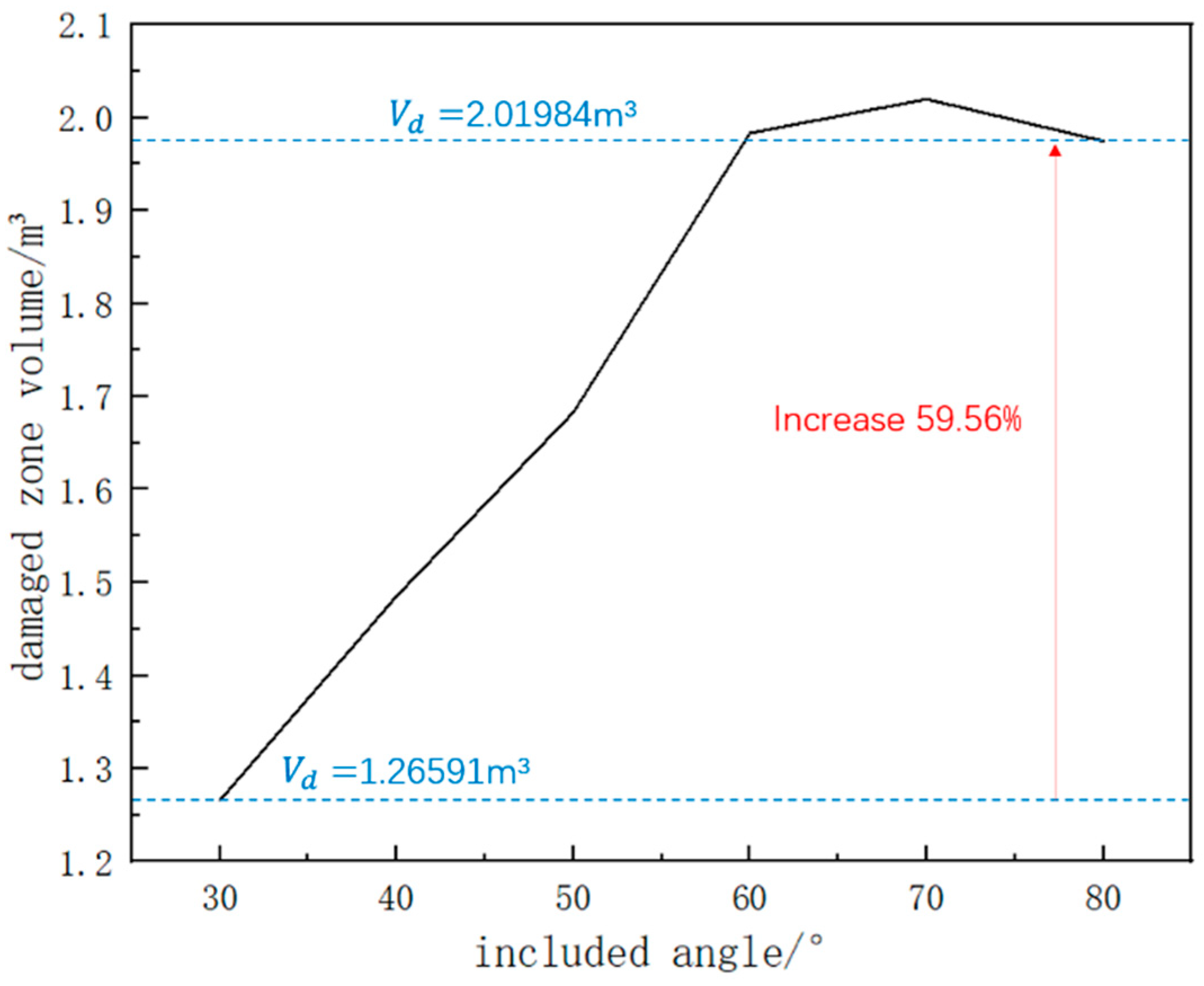
Based on the borehole dimensions used in field explosive blasting, the diameter of the fracturing hole was determined to be 100 mm, with a hole depth of 1.2 m. The charging coefficient was set to 0.5, resulting in an actual charge length of 0.6 m. The load curve corresponding to expansion tube 1 in Figure 5 was selected. The working conditions started at 30°, with intervals of 10°, resulting in six conditions, namely, 30°, 40°, 50°, 60°, 70°, and 80°, covering the range from small-angle sharp fracturing to large-angle stress reflection zones. Figure 6 presents a schematic diagram of the working conditions and the damaged zones under selected conditions.
As shown in Figure 7, when α = 70°, the damaged zone volume V d reaches a peak value of 2.02 m3, representing a 59.56% increase compared to the minimum value of 1.27 m3 under the α = 30° condition. When the inclination angle is between 30° and 70°, the damaged zone volume gradually increases. This is because one side of the expansion tube is too close to the tunnel face, leading to failure along the inherent weak planes of the rock mass, as previously mentioned, resulting in insufficient utilization of the propellant energy. As the angle increases, the influence of the weak planes is reduced, and the damaged zone volume increases accordingly. When the inclination angle ranges from 70° to 80°, a decrease in damaged zone volume is observed, which is attributed to the attenuation characteristics of the gas wedge’s force in intact rock masses. From the perspective of geometric characteristics, the frustum volume formed between boreholes is positively correlated with the hole inclination angle. When the rock-breaking energy satisfies the threshold condition (e.g., at low-angle configurations), the damaged zone extends continuously toward the free surface, thereby achieving rock mass ejection. Under high-angle conditions, the “energy-focusing effect” between adjacent expansion tubes intensifies rock fragmentation in the intermediate zone. However, as the angle further increases, the stress applied to the distal rock mass by the gas wedge diminishes, and the expansion force of the high-pressure gas becomes insufficient to eject the rock from the free surface, resulting in no observed damage in the tunnel face area during the simulation. In practical applications, excessively large angles may result in perforation or the appearance of microcracks on the surface.
This indicates that the inclination angle between the cut hole and the tunnel face is not necessarily better when increased. Under the assumption of a fully continuous medium (i.e., assuming undeveloped rock mass joints), simply increasing the angle may actually reduce rock-breaking efficiency. Therefore, 70° is selected as the optimal inclination angle between the cut hole and the tunnel face.
When the geological condition of the optimal working case is adjusted to mudstone, it is found that applying the same loading curve used for sandstone results in an excessively large damaged zone. This not only makes it difficult to control the excavation contour during the rock-breaking process but also poses potential safety risks. By adjusting the charge density, it is eventually found that when the peak pressure reaches 93.7 MPa (corresponding to expansion tube 3), the damaged zone volume becomes comparable to be observed in sandstone.

3.2.2. Optimization Study on Borehole Spacing Arrangement

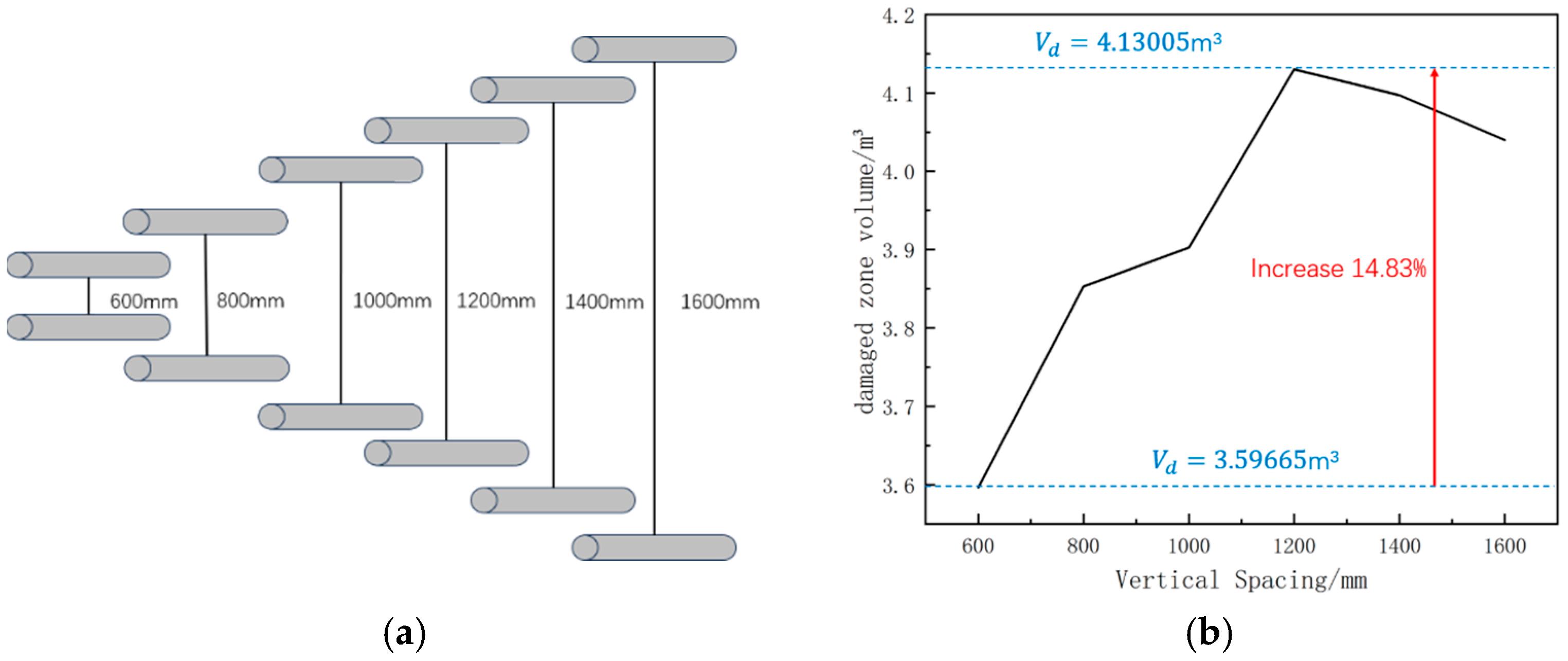
Based on the previously determined optimal single-hole inclination angle α of 70°, and keeping key parameters, such as borehole diameter and charge density constant, simulations were conducted for vertical spacing (H) between double holes ranging from 600 mm to 1600 mm, with a step interval of 200 mm, covering typical engineering requirements.
Figure 8 presents the schematic of the working conditions and the variation in damaged zone volume under the double-hole model with respect to different simulation conditions.
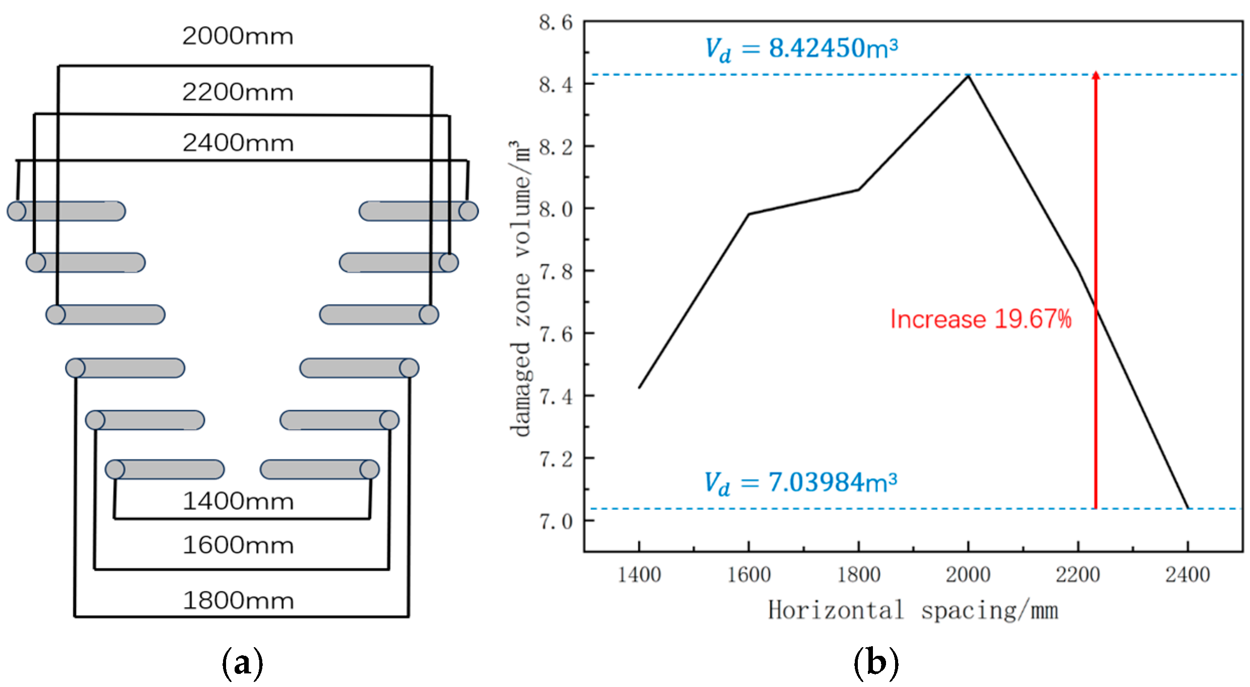
As shown in Figure 8b, when H = 1200 mm, the damaged zone volume   V d reaches a peak value of 4.13 m3, representing a 14.83% increase compared to the minimum value of 3.60 m3 under the condition of H = 600 mm. Therefore, the optimal vertical spacing between boreholes is determined to be H = 1200 mm. In conventional tunnel-blasting excavation, cut holes are generally classified by angle into three types: inclined cuts, straight-hole cuts, and mixed cuts. Given that the inclination angle is 70°, the cut belongs to the inclined type. For inclined cuts, there are generally two layout forms: oblique wedge-shaped cuts and conical cuts. Since conical cuts are mostly suitable for deep-hole blasting, and the borehole depth in this study is only designed to be 1.2 m, the oblique wedge-shaped cut was selected, in which two rows of symmetrical inclined holes were arranged in a “V” shape. Therefore, with α = 70° and H = 1200 mm fixed, the lateral spacing D between the two symmetrical rows of boreholes was investigated. As shown in Figure 9a, six working conditions were simulated with lateral spacing D ranging from 1400 mm to 2400 mm, using a 200 mm interval between conditions.
As shown in Figure 9b, when D = 2000 mm, the damaged zone volume V d reaches a peak value of 8.42 m3, representing a 19.67% increase compared to the minimum value of 3.60 m3 at D = 2400 mm. This indicates that under the current simulation parameters, the optimal lateral spacing between boreholes is D = 2000 mm.
It can be observed from Figure 8b and Figure 9b that the damaged zone volume in both the double-hole and four-hole models shows an overall trend of initially increasing and then decreasing. From the perspective of energy distribution, this process can be divided into three stages: energy dissipation stage, optimal synergistic rock-breaking point, and energy attenuation stage. The energy dissipation stage (H = 400 mm–1200 mm, D = 1400–2000 mm) occurs when the borehole spacing is less than the critical value, causing overlapping of high-pressure gas energy on the facing sides of the boreholes. As a result, most of the energy is dissipated in already fractured rock, leading to poor rock-breaking performance. The optimal synergistic rock-breaking point (i.e., the point of maximum damaged zone volume) occurs at H = 1200 mm and D = 2000 mm. At this spacing, the lateral and vertical boreholes act in optimal synergy, enhancing the gas wedge effect and thus achieving the most effective rock-breaking performance under the current charging parameters. In the energy attenuation stage (H = 1200 mm–1600 mm, D = 2000–2400 mm), the increased distance between the cut holes weakens the interaction between the boreholes, resulting in relative isolation. This makes the rock-breaking performance similar to that of repeated single-hole models, significantly reducing the energy density in the cut zone and thus impairing the overall effectiveness.
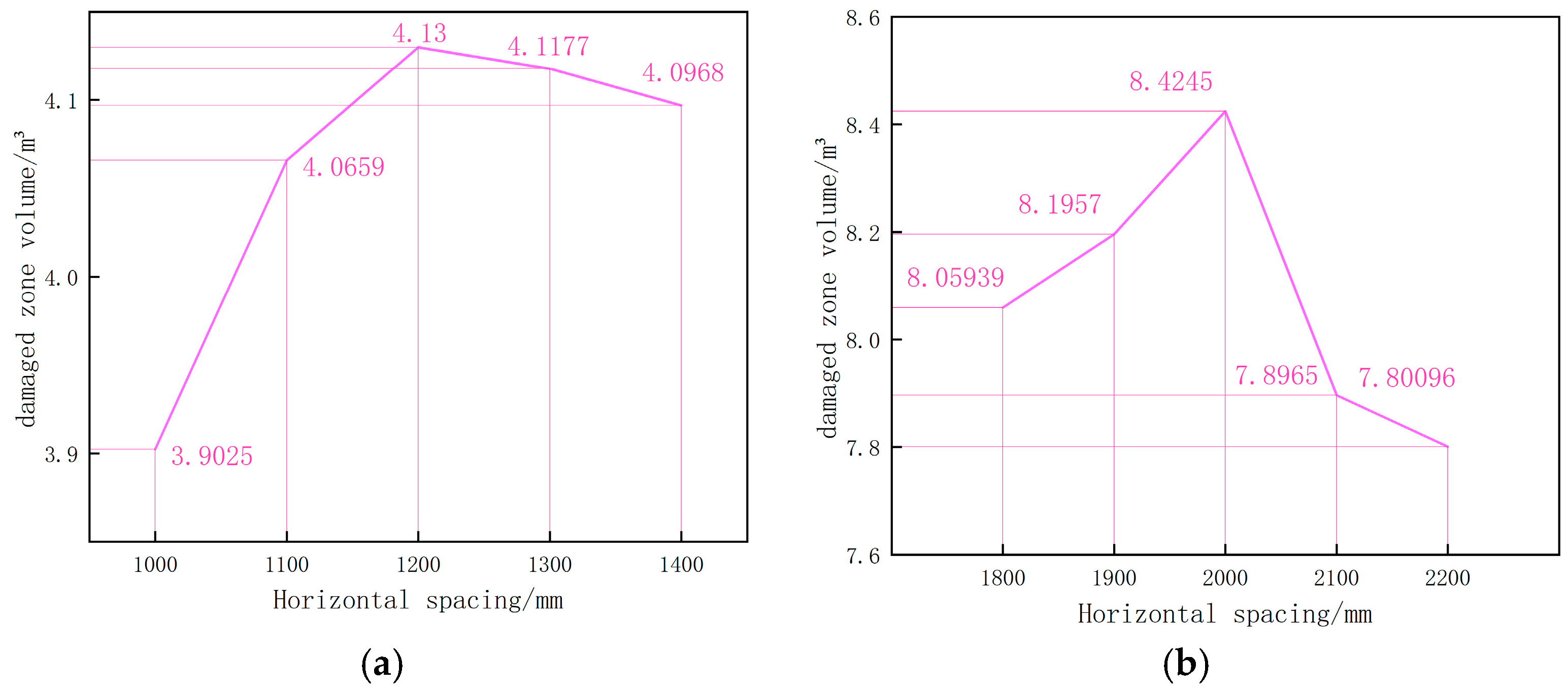
Additionally, to ensure the robustness of the identified optimal working conditions, a sensitivity analysis was conducted to investigate the damage zone characteristics within a ±100 mm variation range around the optimal parameters. As illustrated by the damage zone volume variation curve in Figure 10, when the parameter scale was adjusted by 100 mm, the configuration of H = 1200 mm and D = 2000 mm still exhibited the best performance, confirming its validity as the optimal working condition.
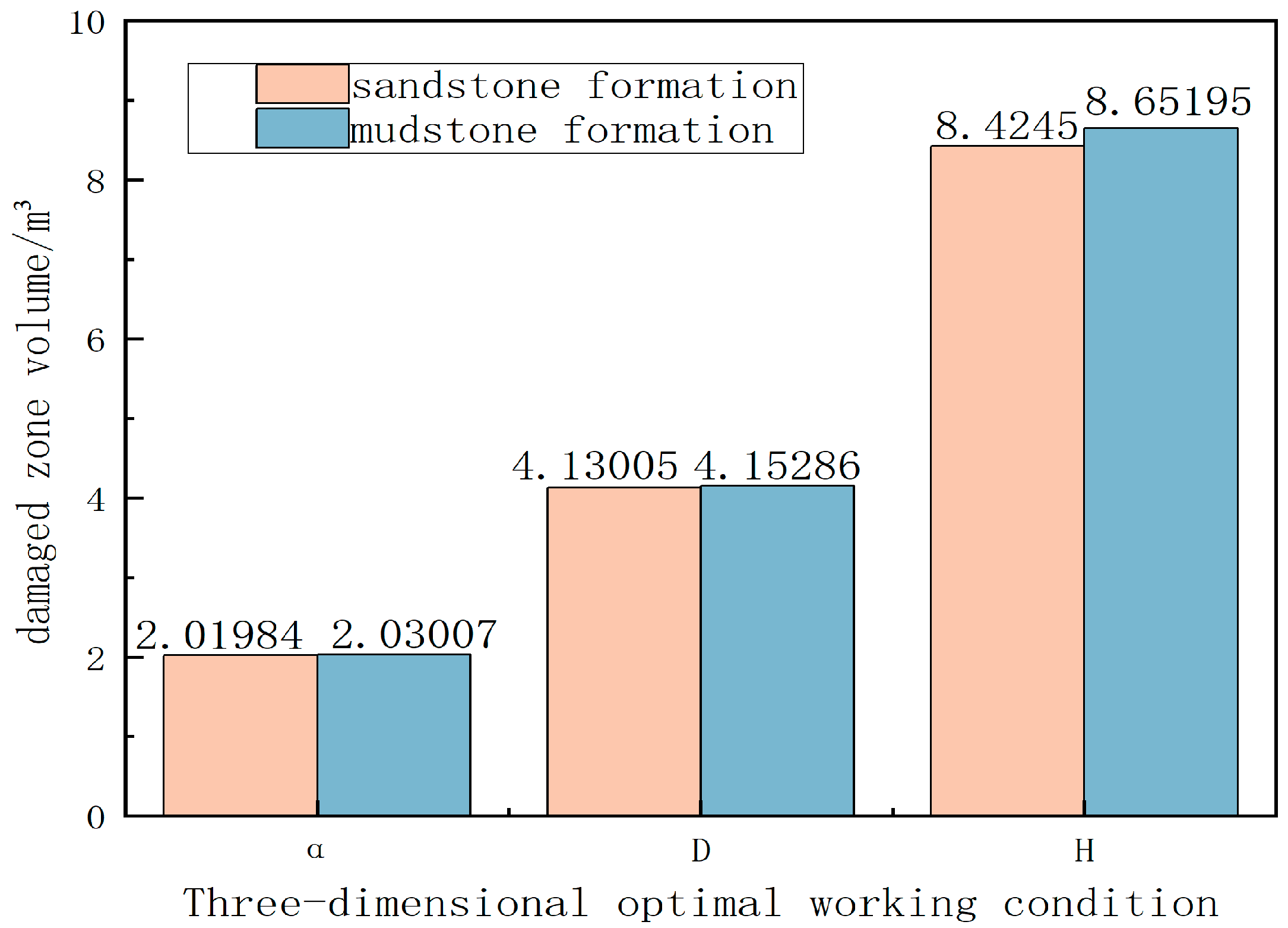
Similarly, in the previous study, the charge density suitable for mudstone strata and a complete set of borehole parameters for the cut zone in sandstone strata were obtained. By applying the load curve of expansion tube 3 (Figure 5) to the optimal configurations of both the double-hole and four-hole models, the damaged zone volumes under the three optimal scale conditions were compared, as shown in Figure 11. The differences were all within 3%. This confirms that, for the cut zone, achieving comparable rock-breaking effects across different strata is feasible by controlling the charge density.

3.3. Study on Auxiliary Borehole Parameters

Auxiliary holes are a key link in tunnel blasting, playing a crucial role in bridging the upper and lower stages of the blasting process. On the one hand, they utilize the free face created by the cut holes to peel off the rock layers and gradually expand the blasting range. On the other hand, they help distribute the energy from the cut holes, preventing over-excavation or excessive vibrations caused by excessive energy concentration.
In previous studies, the optimal parameters for three scales—the angle α between the cut hole and the tunnel face, the vertical spacing H, and the horizontal spacing D—were determined for the specific engineering context. Based on the engineering cross-section, four cut holes were proposed to be set. Using the above optimal parameters, the rock-breaking effects in the cut zone for both sandstone and mudstone strata were simulated.
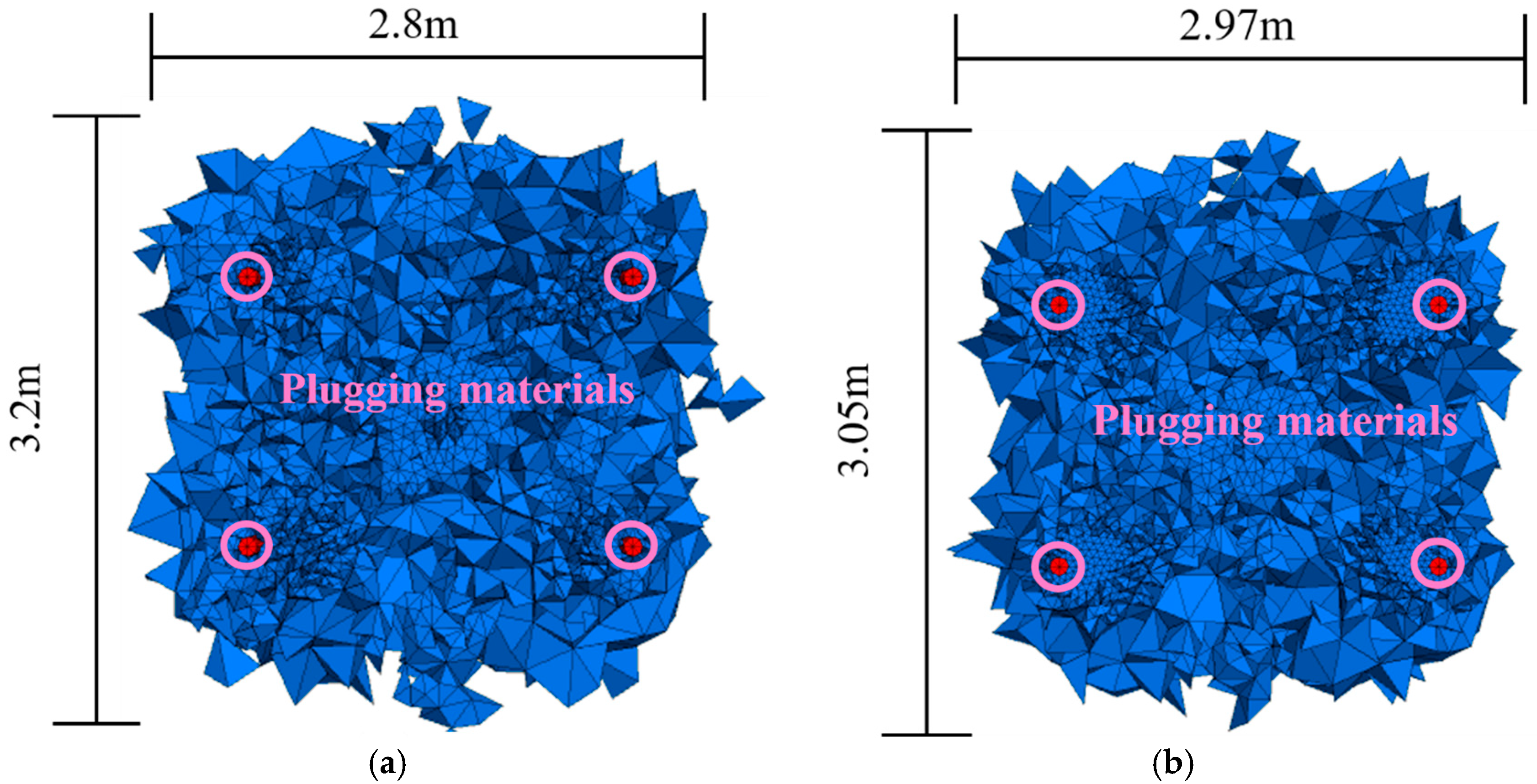
As shown in Figure 12, in both sandstone and mudstone strata, the rock-breaking effect in the cut zone is satisfactory, with a continuous internal damaged zone that can connect to the tunnel face.
To study the auxiliary hole network parameters, the damaged zone caused by the cut hole was approximated as a cube and removed from the tunnel cross-section model, as shown in Figure 13. This served as an equivalent replacement for the free face created by the cut hole, facilitating the study of the auxiliary hole network parameters. A commonly used ring arrangement was adopted, with a layout of 500 mm × 500 mm. The load curves corresponding to expansion tubes 2 and 4 in Figure 5 were applied to the walls of the auxiliary holes in both sandstone and mudstone strata. The rock-breaking effects in sandstone and mudstone are shown in Figure 14. It can be observed that after the detonation of the auxiliary holes, the inter-hole fractures are connected, and the damaged zone has a large area of connection with the free face. This indicates that under the current borehole spacing, the auxiliary holes can achieve a good rock-peeling effect. This demonstrates that the current arrangement is suitable for the geological conditions of the project. Based on this, the cut holes were incorporated into the model, and a delayed detonation method was used to simulate the overall rock-breaking effect in both sandstone and mudstone strata under the current borehole network parameters. In the specific implementation, the cut holes were detonated at t = 0 ms, and the auxiliary holes were detonated at t = 60 ms, t = 120 ms, and t = 180 ms in sequence to avoid simultaneous energy output that could impact personnel and the environment, while also achieving dual control objectives. The borehole network parameters are selected as shown in Table 4.
Figure 14 and Figure 15 show that under the current borehole network parameters, both the auxiliary and cut zone damage areas are interconnected in both sandstone and mudstone strata. The overall rock fragmentation profile closely matches the tunnel profile, with minimal over-excavation or under-excavation, meeting the engineering quality requirements. This demonstrates that (1) the use of high-pressure gas expansion for rock breaking is feasible in terms of the rock-breaking effect and (2) in high-pressure gas expansion rock breaking, adjusting the charge density makes it feasible to apply a complete set of borehole network parameters to different geological environments within the same project.

4. Vibration Safety Analysis

4.1. Vibration Analysis in Building Areas

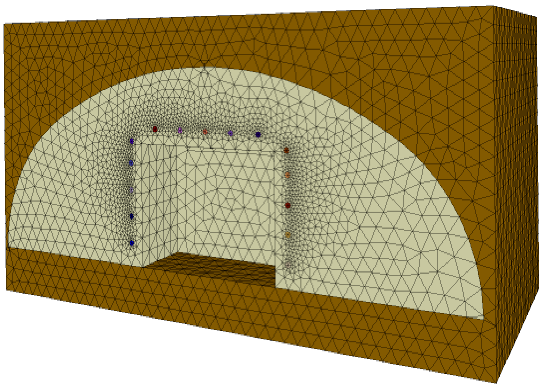
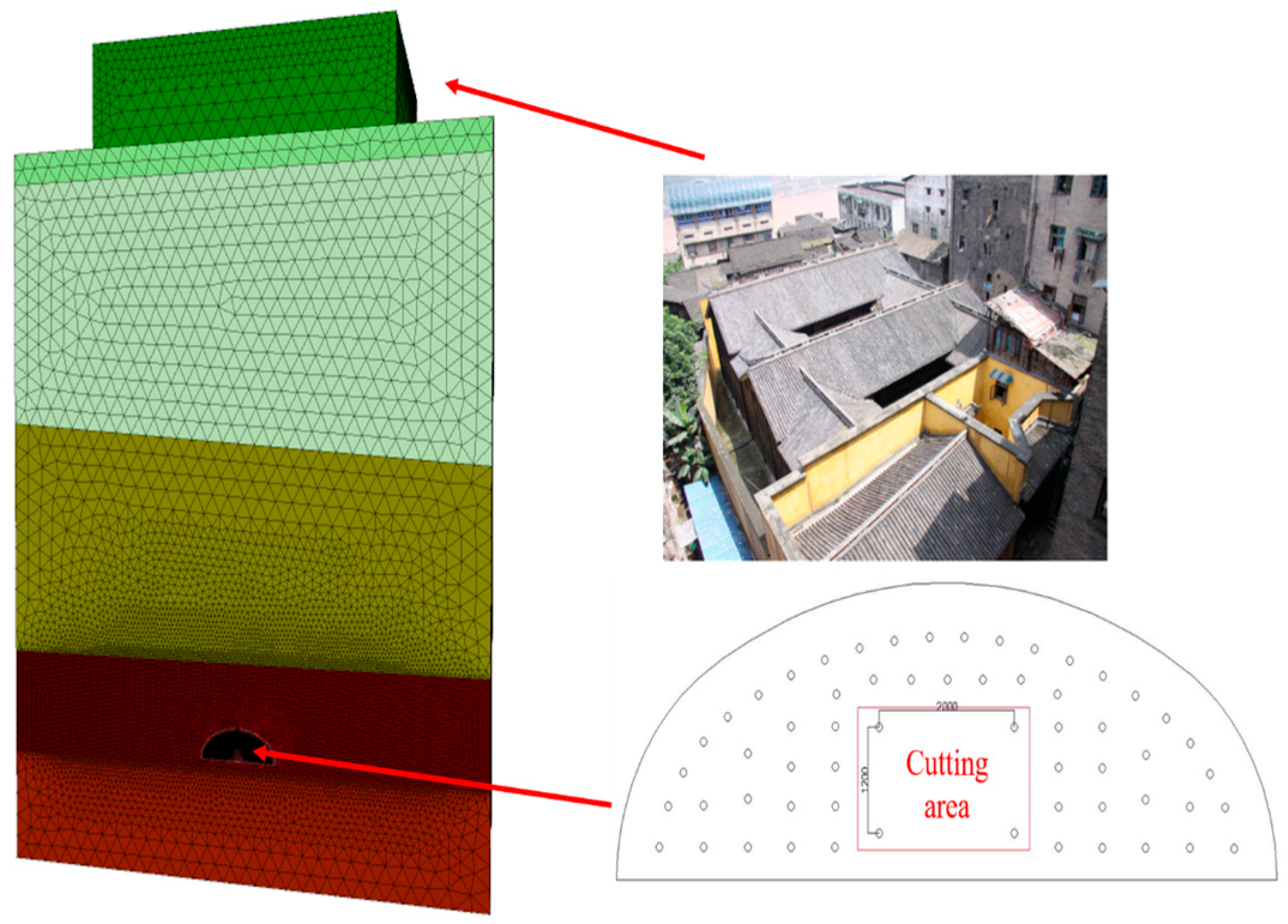
Along the blasting excavation section of the North Extension Project of Chongqing Metro Line 18 at Kaixuan Station, numerous buildings are located. Notably, directly above the tunnel lies the Xie Family Courtyard, a building constructed in the late Qing Dynasty. It is a key protected cultural relic and a valuable historical and cultural heritage site. Vibrations generated by both blasting and non-blasting excavation methods cannot be ignored, especially considering that historical and cultural buildings, once damaged, are often difficult to restore. Therefore, to ensure the practical feasibility of the high-pressure gas expansion rock-breaking method in this project, its safety must also be evaluated in terms of vibration effects. Given the unique characteristics of the Xie Family Courtyard and its high sensitivity to vibrations—along with the absence of similar structures along the blasting section—it was selected as the primary subject of study, with vibration velocity adopted as the evaluation metric. As long as the vibration velocity at the Xie Family Courtyard remains within the safety threshold, it can be concluded that the use of high-pressure gas expansion for excavation is safe for the entire blasting section of the project. The tunnel section located directly beneath the Xie Family Courtyard—its closest point—was selected as the simulation region. A numerical model was established using FLAC3D 6.0 simulation software, and a schematic of the model is shown in Figure 16.
According to national standards and on-site blasting requirements, the peak particle velocity (PPV) at any location within the structure of Xie’s Residence should be less than 0.3 cm/s. Considering the advantage of high-pressure gas expansion rock fracturing in producing lower disturbance compared with explosive blasting, as well as the structural degradation of Xie’s Residence caused by centuries of natural weathering and superimposed human activities, which has made it increasingly fragile, a smaller PPV is required to further ensure its safety. Therefore, in this simulation, a stricter control criterion was adopted, requiring that the PPV at any location of Xie’s Residence remain below 0.1 cm/s.
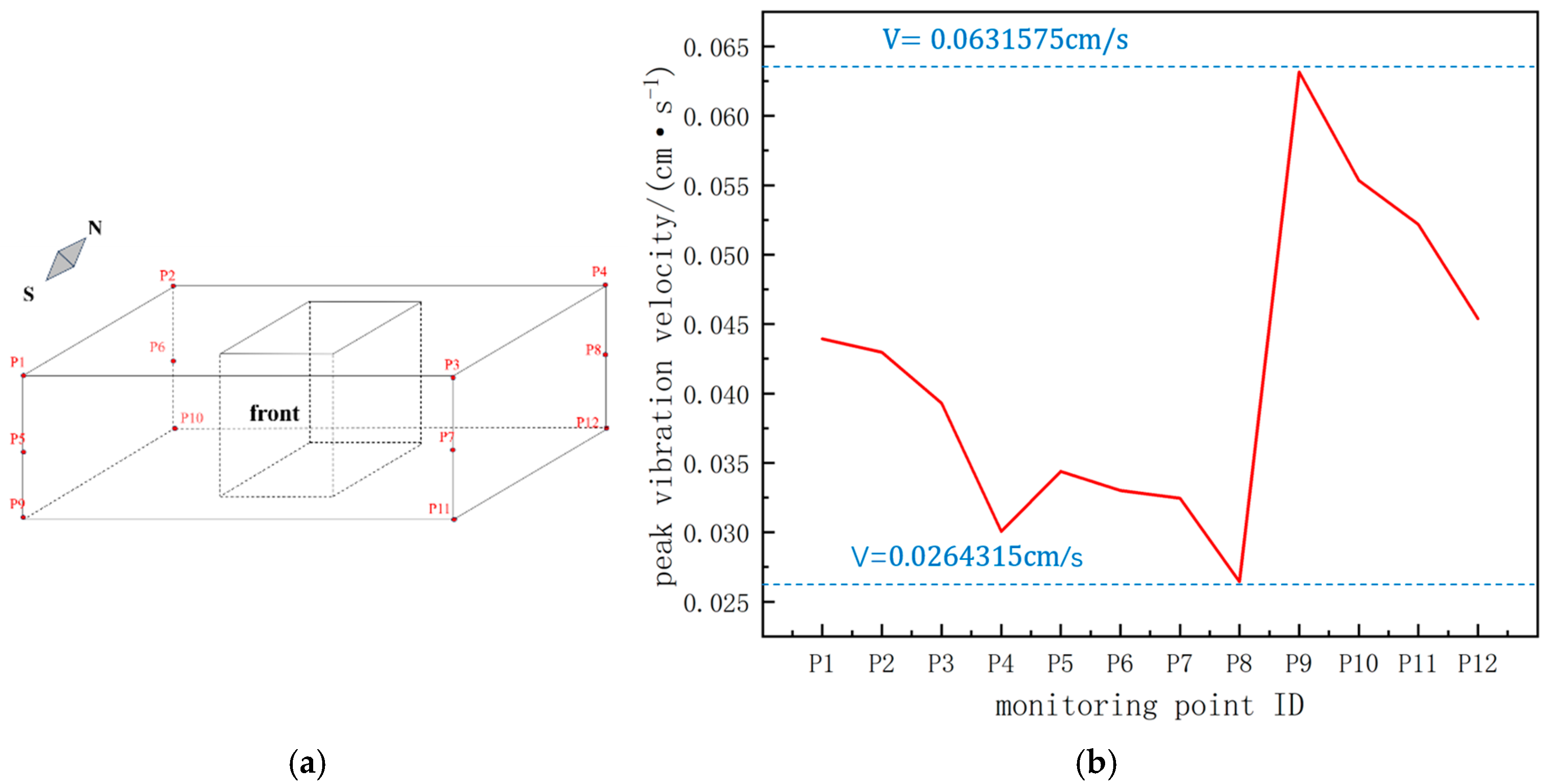
During the simulation phase, four monitoring points were set at the ground (h = 0), the middle of the building (h = 5), and the roof area (h = 10) of the Xie Family Courtyard to study the effects of vibration velocity on different structural parts of the building and the propagation pattern of vibration velocity. The simulation was conducted according to the borehole network parameters described in Section 3.3 of this article. Figure 17 presents the layout of the monitoring points and the variation of the peak vibration velocities at each monitoring point.
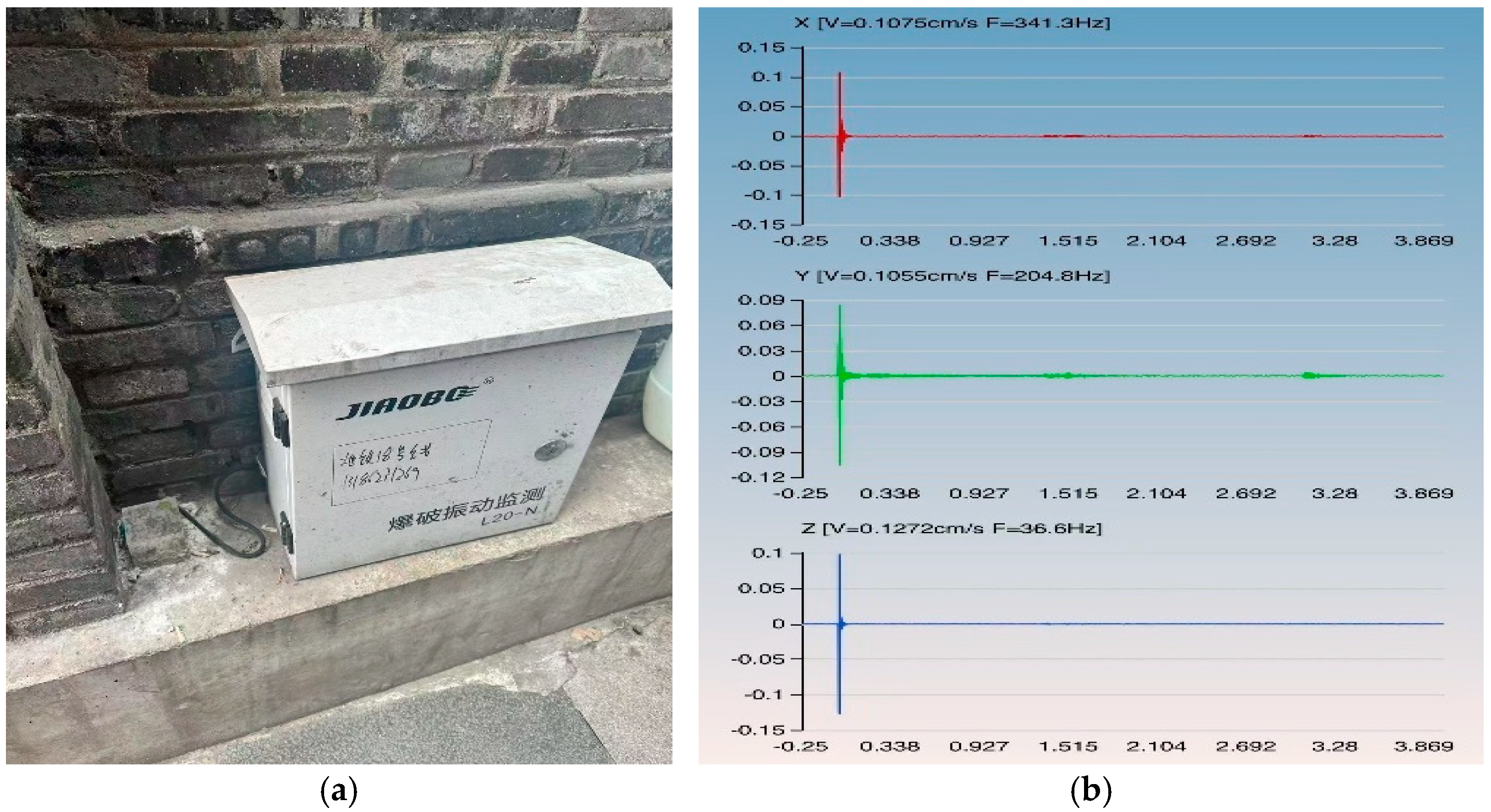
As shown in Figure 17b, among the 12 monitoring points, the maximum vibration velocity was observed at point P10, with v = 0.0631575 cm/s, while the minimum was recorded at point P6, with v = 0.0264315 cm/s. The peak vibration velocities at all 12 monitoring points were below 0.1 cm/s. On-site, an L20-N blasting vibration monitor was installed on the ground at the northeast corner of the Xie Family Courtyard, which corresponds to the location of monitoring point P12. Figure 18 illustrates the field location of the monitoring point and the vibration velocity curve recorded during monitoring.
As shown in the figure, the resultant peak vibration velocity was 0.1971 cm/s, indicating that when excavating the same tunnel face, the vibration velocity induced by high-pressure gas expansion rock breaking was reduced by approximately 67.95% compared to that induced by explosive rock breaking at the same location. In terms of vibration velocity, high-pressure gas expansion rock breaking exhibits clear advantages over explosive blasting, with its safety performance more in line with engineering standard requirements.
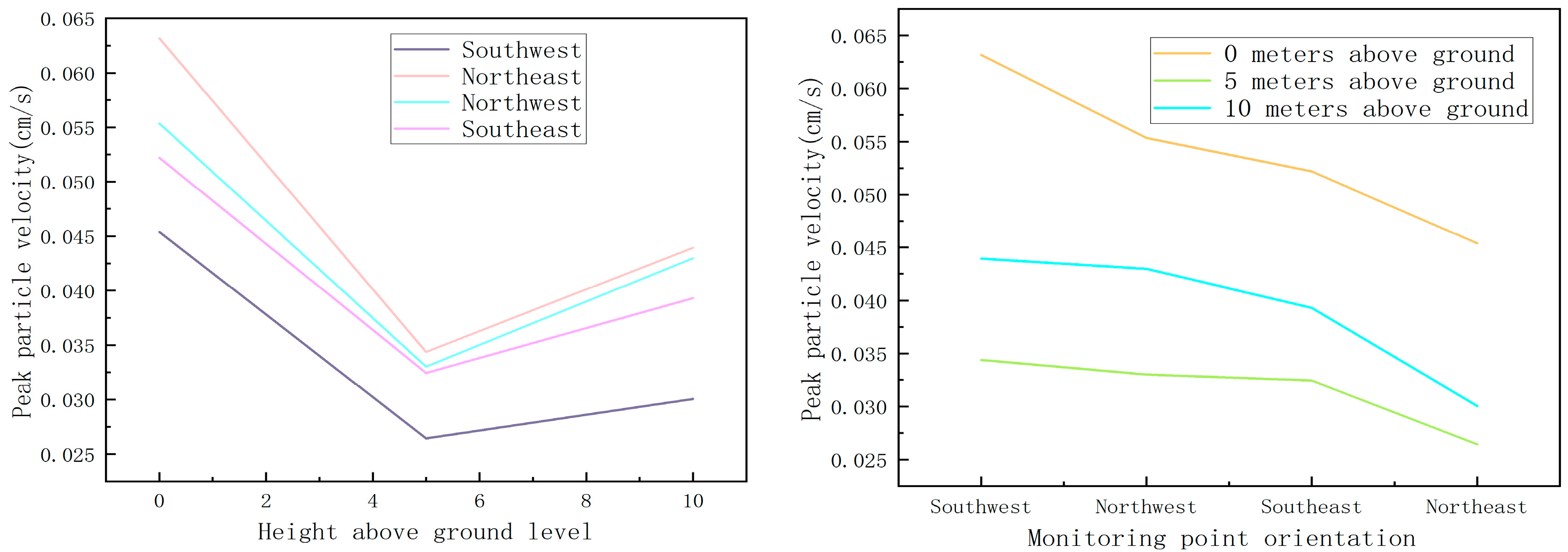
According to Figure 17a, the monitoring points set within the Xie Family Courtyard can be grouped based on horizontal and vertical directions. The variation in peak vibration velocity for both the horizontal and vertical groupings is illustrated in Figure 19.
As shown in Figure 18, with the increase in monitoring point height, the peak vibration velocities of the four monitoring groups first increased and then decreased. This phenomenon can be attributed to the fact that when vibration waves initially enter the building, the bottom part typically possesses higher stiffness and mass, which enables it to absorb part of the vibration energy, resulting in the attenuation of vibration velocity. As the blasting-induced vibration continues to propagate upward, the vibration velocity begins to increase gradually from a certain height within the building. This phenomenon is referred to as the “elevation amplification effect”, which occurs because the stiffness and mass of the building decrease closer to the top, making it more susceptible to resonance with vibration waves. This resonance leads to wave superposition, resulting in an increase in vibration velocity.

4.2. Vibration Analysis in the Tunnel Face Area

In the previous section, the vibration behavior of the structures located directly above the tunnel face was analyzed. However, due to the considerable burial depth of the tunnel in the selected simulation area, most of the vibration energy was attenuated during propagation through the strata, and the particle velocity measured at the ground surface was already minimal. Nevertheless, due to the topographic characteristics of the urban core area, where the terrain fluctuates significantly, the tunnel depth along the alignment varies considerably, with the deepest point reaching approximately 71 m and the shallowest about 43 m, resulting in a maximum elevation difference of 28 m. In order to better visualize the vibration impact of high-pressure gas expansion rock breaking on the surrounding environment and to provide more accurate data support for vibration safety control, a vibration safety analysis of the tunnel face rock-breaking zone was conducted in the following section.
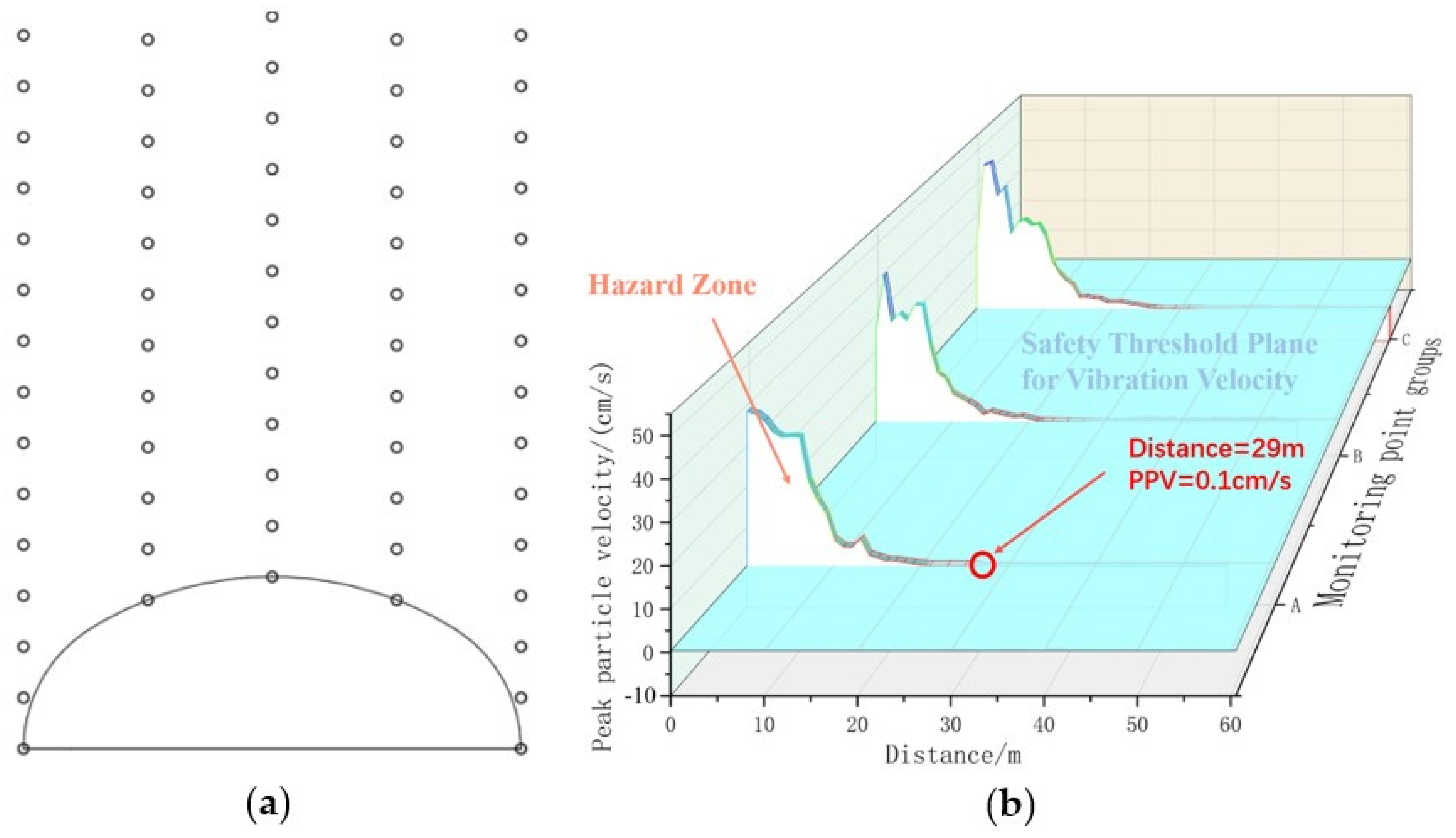
During blasting at the working face, if the vibration impact on the structure directly above remains within safety standards, the vibration impact on surrounding structures of the same type is generally also within safe limits. Therefore, using the working face as the radial analysis plane, five columns of vertical monitoring points were set above the working face, distributed symmetrically around the axial center, to obtain peak vibration velocity data within a specific area around the blast center. Since vibration velocity varies more significantly in areas closer to the blast center and relatively less in areas farther away, a dynamic spacing arrangement was adopted. In practice, the distribution intervals for monitoring points within a single column were as follows: Points 1–20 were spaced 1 m apart; Points 21–30 were spaced 2 m apart; Points 31 to the ground surface were spaced 4 m apart. The monitoring point located on the tunnel contour served as the starting point (distance 0) for each group. Figure 20 illustrates the partial distribution of monitoring points and the variation in peak vibration velocity with distance.
Since monitoring point groups B, E and C, F are symmetrically distributed, only monitoring point groups A, B, and C were selected as the research subjects. Moreover, as this section primarily studies the vibration of the structures directly above the tunnel face, the main focus was on group A. From the figure, it can be observed that for group A data, when the distance from the tunnel face is less than 29 m, the peak vibration velocity exceeds the safety threshold of 0.1 cm/s; when the distance is greater than 29 m, the peak vibration velocity is within the safety threshold. This indicates that under the current engineering geological conditions, when high-pressure gas expansion rock breaking is applied, and assuming no elevation amplification effect of the buildings, if the tunnel depth exceeds 29 m, the vibration impact on surface structures from rock breaking remains within the safe range. If the tunnel depth is less than 29 m, adjustments to the charge density or borehole layout parameters are required to reduce the disturbance caused by rock breaking to the surface structures. According to the blasting vibration safety standards, except for ancient buildings, the minimum peak vibration velocity requirement for other types of buildings is 0.5 cm/s. Accordingly, under the assumption of no elevation amplification effect, if the tunnel depth is less than 20 m, the vibration impact on surface structures from rock breaking remains within the safe range.

5. Discussion

The research in this paper provides a theoretical basis for the field application of high-pressure gas expansion rock breaking. This section will discuss the specific value of the research, its limitations, and future research directions.

5.1. Research Significance

In this study, a conceptual approach was proposed in which a single set of borehole network parameters could be applied to both sandstone and mudstone strata by adjusting the charge density. Numerical simulations of single-hole, double-hole, four-hole, and full-face excavation scenarios demonstrated that comparable rock fracturing effects could be achieved in the two strata, thereby confirming the feasibility of the proposed scheme. From the perspective of safety, expansion tubes possess advantages over explosives in terms of transportation, storage, and operational simplicity. Moreover, comparative analysis of field data and simulation results revealed that, during excavation of the same tunnel face, the vibration velocity induced by high-pressure gas expansion rock fracturing was approximately 67.95% lower than that of explosive blasting. From an economic perspective, the cost of expansion tubes was about 1.5–2.5 times higher than that of explosives, partly because mass production and mechanized manufacturing processes have not yet been established and partly because the limited consumption of gas-generating agents has prevented further cost reduction. These findings indicate that expansion tubes indeed provide certain advantages over explosives; however, due to limitations in economic efficiency and standardization, they can currently only serve as a suitable alternative to explosives in specific sensitive areas. In future development, the method may be extended to more strata, with charge density adjusted in real time based on drilling data in order to achieve the use of a single borehole network parameter under complex geological conditions, thereby saving considerable time and economic cost.

5.2. Research Limitations

The underground strata in Chongqing are complex, and the entire project crosses several strata repeatedly. In this study, only the cases where the tunnel face is entirely within sandstone or entirely within mudstone were considered, without taking into account the case where the tunnel face is located within a sandstone–mudstone interbedded layer. No further investigation was conducted regarding the interbedded case, where different pressures are applied to the fracturing holes in different strata under the same borehole parameters, to determine whether the expected rock-breaking effect can still be achieved. Furthermore, since this project is located in the central area of Yuzhong District in Chongqing, which is a highly environmentally sensitive area, with strict engineering schedule requirements and construction standards, on-site testing could not be conducted. This study only demonstrates the theoretical feasibility of the proposed scheme and does not verify its practical feasibility through experimental testing.

5.3. Future Research Directions

In the engineering background of this study, interbedded sandstone–mudstone strata were present. The feasibility of the method in both sandstone and mudstone was verified in Section 3.2.1 and Section 3.2.2, where comparable rock fracturing effects were achieved with different charge densities in the two strata. Therefore, when the tunnel face is located in a sandstone–mudstone interbedded zone, it is theoretically feasible to adopt one charge density for fracturing holes in sandstone and another for those in mudstone, thereby achieving rock fracturing effects similar to those obtained in single lithologies. Future research may focus on the application of high-pressure gas expansion rock fracturing in more complex underground environments, with greater integration of actual tunnel face information, so as to ensure effective rock fracturing while further controlling vibration.
Furthermore, future research should also focus on the adaptability of high-pressure gas expansion rock breaking in special underground environments, such as in extremely hard rocks or in water-rich strata, to determine whether the expansion tube can still achieve the expected engineering results. Discrete element analysis software should be used to focus on studying the rock-breaking mechanism and crack propagation around the fracturing holes in high-pressure gas expansion rock breaking in order to establish a quantitative analysis method for evaluating the rock-breaking effect of the expansion tube. Since high-pressure gas expansion rock breaking has not yet formed a systematic rock-breaking scheme, including charge density and borehole layout parameters, its application currently relies more on numerical simulations prior to engineering practice to provide theoretical guidance. In the future, high-pressure gas expansion rock-breaking experiments can be conducted in various strata to fill the gap in this field, aiming to develop a practical and systematic rock-breaking scheme. In conclusion, this study, through numerical simulations, explores the optimal borehole layout parameters for high-pressure gas expansion rock-breaking excavation of the safety passage at Kaixuan Station. Furthermore, after controlling the charge density, these borehole parameters can continue to be applied in mudstone strata, providing a reference for field engineering practice. Future research can build upon the findings of this study to explore the application of high-pressure gas expansion rock breaking in more complex and special geological environments.

6. Conclusions

In this study, three configurations—single-hole, double-hole, and four-hole—were designed using numerical simulation software. Taking the damaged zone as the primary evaluation index, the optimal intersection angle α between the cut hole and the tunnel face, the optimal vertical spacing H, and the optimal horizontal spacing D were determined. Furthermore, a method was proposed to enable the same set of borehole parameters to be applicable to different strata by adjusting the charge density. The feasibility of the rock-breaking effect was verified through full-scale simulation, while also considering the protection of vibration-sensitive surface structures. The main findings of this study are as follows:
(1) Due to the presence of the “gas wedge” effect, the rock mass is inevitably driven by high-pressure gas to fracture along weak surfaces. In high-pressure gas expansion rock breaking, rock fragmentation predominantly occurs along pre-existing joints, resulting in relatively smooth post-fracture surfaces. Under simultaneous initiation of multiple boreholes, synergistic interaction exists among the holes; expansion tubes can provide “weak surfaces” for each other, enhancing the gas wedge effect and strengthening the connection between the damaged zone and the free surface, thereby facilitating more effective expulsion of fragmented rock.
(2) The present study shows that, under the current engineering conditions, the optimal rock-breaking angle is 70°, with an optimal vertical spacing of 1200 mm and an optimal horizontal spacing of 2000 mm. For auxiliary holes, the optimal borehole arrangement is 500 mm × 500 mm. A conceptual approach was proposed to apply a unified set of borehole parameters to both sandstone and mudstone formations by controlling the charge density, and its theoretical feasibility was validated through numerical simulations. This approach can potentially reduce manpower and time consumption in actual engineering projects.
(3) Considering the significant topographic variation in the core area of Chongqing, the radial peak particle velocity distribution at the tunnel face was studied to distinguish between safe and hazardous zones. The results indicate that if high-pressure gas expansion rock breaking is employed throughout the entire project and the tunnel burial depth is not less than 29 m, the surface structures would remain within the vibration safety threshold.

Author Contributions

Methodology and writing guidance, D.L.; writing—preparing the manuscript, J.Z.; writing—review and editing, D.L., Y.J. and J.Z.; data collection, Y.Z.; numerical simulation, J.Z. and Y.J.; data curation, Y.J. and Y.Z. All authors have read and agreed to the published version of the manuscript.

Funding

This research received no external funding.

Data Availability Statement

All data used in this paper is derived from field testing and numerical simulations, with no external data incorporated. Furthermore, all data referenced in this paper is fully documented within the text.

Conflicts of Interest

The authors declare that they have no known competing financial interests or personal relationships that could have appeared to influence the work reported in this paper.

References

  1. Wang, F.; Zhou, D.; Zhou, X.; Xiao, N.; Guo, C. Rock Breaking Performance of TBM Disc Cutter Assisted by High-Pressure Water Jet. Appl. Sci. 2020, 10, 6294. [Google Scholar] [CrossRef]
  2. Shangguan, J.; Ge, Z.; Zhou, Z.; Zhang, X.; Liu, L.; Li, Z. Experimental study on dynamic deformation and breaking mechanism of high-temperature hard rock cutting by abrasive water jet. Int. J. Rock Mech. Min. Sci. 2024, 180, 105797. [Google Scholar] [CrossRef]
  3. Gao, Y.; Han, P.; Wang, F.; Cao, J.; Zhang, S. Study on the Characteristics of Water Jet Breaking Coal Rock in a Drilling Hole. Sustainability 2022, 14, 8258. [Google Scholar] [CrossRef]
  4. Liu, S.; Li, H.; Chang, H. Drilling Performance of Rock Drill by High-Pressure Water Jet under Different Configuration Modes. Shock. Vib. 2017, 2017, 5413823. [Google Scholar] [CrossRef]
  5. Reinsch, T.; Paap, B.; Hahn, S.; Wittig, V.; Berg, S.v.D. Insights into the radial water jet drilling technology-Application in a quarry. J. Rock Mech. Geotech. Eng. 2018, 10, 236–248. [Google Scholar] [CrossRef]
  6. Zhang, K.; Xiao, S.; Liu, W.; Wang, D.; Zhang, G. Feasibility study of an adjustable-power laser cutting head for TBM applications: Focus on rock fragmentation efficiency and energy consumption. Tunn. Undergr. Space Technol. 2025, 155, 106155. [Google Scholar] [CrossRef]
  7. Ma, Z.; Zhang, C.; Li, C.; Wei, W.; Dong, J. Laser rock-breaking mechanism considering rock inhomogeneity and the temperature effect. Comput. Geotech. 2025, 179, 107029. [Google Scholar] [CrossRef]
  8. Jamali, S.; Wittig, V.; Börner, J.; Bracke, R.; Ostendorf, A. Application of high powered Laser Technology to alter hard rock properties towards lower strength materials for more efficient drilling, mining, and Geothermal Energy production(Article). Geomech. Energy Environ. 2019, 20, 100112. [Google Scholar] [CrossRef]
  9. Guo, C.; Sun, Y.; Yue, H.; Li, Q.; He, S.; Zhang, J.; Zhang, Y. Experimental research on laser thermal rock breaking and optimization of the process parameters. Int. J. Rock Mech. Min. Sci. 2022, 160, 105251. [Google Scholar] [CrossRef]
  10. Yu, B.; Niu, S.; Zhou, S.; Lei, Y.; He, Z.; Luo, X. Impact Pressure Characteristics of Carbon Dioxide Phase Transition Fracturing Technique. ACS Omega 2024, 9, 23927–23939. [Google Scholar] [CrossRef] [PubMed]
  11. Liu, X.; Nie, B.; Guo, K.; Zhang, C.; Wang, Z.; Wang, L. Permeability enhancement and porosity change of coal by liquid carbon dioxide phase change fracturing. Eng. Geol. 2021, 287, 106106. [Google Scholar] [CrossRef]
  12. Zhou, S.; Luo, X.; Jiang, N.; Zhang, S.; Lei, Y. Ground vibration characteristics of carbon dioxide phase transition fracturing: An in situ test. Bull. Eng. Geol. Environ. 2021, 80, 9029–9047. [Google Scholar] [CrossRef]
  13. Xia, J.; Dou, B.; Tian, H.; Zheng, J.; Cui, G.; Kashif, M. Research on Initiation of Carbon Dioxide Fracturing Pipe Using the Liquid Carbon Dioxide Phase-Transition Blasting Technology. Energies 2021, 14, 521. [Google Scholar] [CrossRef]
  14. Liu, J.; Liu, H.; Shi, F.; Zhou, Y.; Sun, M.; Wu, S.; Zhou, X.; Li, S. Rock breaking using liquid nitrogen and water jet: A case of granite. Arch. Civ. Mech. Eng. 2025, 25, 1–21. [Google Scholar] [CrossRef]
  15. Zou, Z.; Cai, C.; Wang, B.; Gao, Y.; Tao, Z.; Feng, Y. Complex Flow Mechanism and Pressurization Effect of Liquid Nitrogen Jet Fracturing Formation Perforation Tunnel. Processes 2023, 11, 2878. [Google Scholar] [CrossRef]
  16. Xue, Y.; Yao, L.; Li, J.; Ding, L.; Luo, W.; Zhou, X.; Wang, S.; Zhao, Y. Temporal and spatial evolution laws of temperature effects in high-velocity liquid nitrogen jet rock breaking. Appl. Therm. Eng. 2024, 255, 124060. [Google Scholar] [CrossRef]
  17. Cai, C.; Yang, Y.; Liu, J.; Gao, F.; Gao, Y.; Zhang, Z. Downhole Transient Flow Field and Heat Transfer Characteristics During Drilling With Liquid Nitrogen Jet. J. Energy Resour. Technol. 2018, 140, 122902. [Google Scholar] [CrossRef]
  18. Ren, F.; Fang, T.; Cheng, X. Theoretical modeling and experimental study of rock-breaking depth in particle jet impact drilling process(Article). J. Pet. Sci. Eng. 2019, 183, 106419. [Google Scholar] [CrossRef]
  19. Fang, T.; Wang, B.; Cheng, T.; Ren, F. Stress Modeling and Simulation Analysis of Particle Impact Rock-Breaking. In Proceedings of the International Forum on Electrical Engineering and Automation, Hefei, China, 25–27 September 2020. [Google Scholar]
  20. Huang, S.; Mohanty, B.; Xia, K. A multi-particle crushing apparatus for studying rock fragmentation due to repeated impacts. Rev. Sci. Instrum. 2017, 88, 125114. [Google Scholar] [CrossRef] [PubMed]
  21. Liu, Y.; He, L.; Dai, L.; Shen, K.; Ba, Q. Analysis of Rock Breaking Parameters and Simulation of Mechanical Characteristics of Multi-Nozzle Jet Impact. Sustainability 2023, 15, 12414. [Google Scholar] [CrossRef]
  22. Wei, H.; Wang, C.; Zhu, J.; Yang, X.; Chu, H. Propagation characteristics of stress wave in layered rock mass under the impact of high-pressure gas. Proc. Inst. Civ. Eng.-Geotech. Eng. 2023, 177, 303–322. [Google Scholar] [CrossRef]
  23. Peng, H.; Sheng, J.; Da, Q.; Dai, B.; Zhang, L.; Tan, L. The Vibration Response to the High-Pressure Gas Expansion Method: A Case Study of a Hard Rock Tunnel in China. Appl. Sci. 2024, 14, 6645. [Google Scholar] [CrossRef]
  24. Liu, D.W.; Zhang, Z.L.; Chu, F.J.; Jian, Y.H.; Zhang, S.; Huang, Z. Experimental study on rock-breaking by slotting using high-pressure gas expansion method in urban small cross-section hard rock tunnels. Blasting 2019, 36, 104–111. [Google Scholar]
  25. Peng, H.-D.; Liu, D.-W.; Chu, F.-J.; Jian, Y.-H. Test on high pressure gas expansion rock fragmentation in hard rock tunnel. Rock Soil Mech. 2018, 39, 242–248. [Google Scholar]
  26. Pan, Q.; Zhang, J.C.; Shi, H.C.; Zou, X.K.; Deng, X.F.; Xu, H. Study on damage distribution characteristics of rock mass under single-hole non-coupled charge blasting. J. Vib. Shock. 2019, 38, 264–269. [Google Scholar]
  27. Wang, S.; Gong, M.; Wu, H.; Wu, X.; Liu, X. Optimization Study of Water Interval Charge Structure Based on the Evaluation of Rock Damage Effect in Smooth Blasting. Appl. Sci. 2024, 14, 2868. [Google Scholar] [CrossRef]
  28. Tang, W.; You, Y.; Hu, F.; Bian, Y.; Xiao, C.; Zhu, Y.; Meng, T. Experimental Study on SHPB Dynamic Mechanical Response in Different Damaged zones of Rock under Blast Load. Shock. Vib. 2022, 2022, 1–9. [Google Scholar] [CrossRef]
  29. Zhang, Z.; Qiu, X.; Shi, X.; Luo, Z.; Chen, H.; Zong, C. Burden effects on rock fragmentation and damage, and stress wave attenuation in cut blasting of large-diameter long-hole stopes. Rock Mech. Rock Eng. 2023, 56, 8657–8675. [Google Scholar] [CrossRef]
  30. Liu, D.; Wang, C.; Yang, C.; Zhang, W.; Cao, K. Model experimental study on high-pressure gas expansion directional rock-cracking based on directional expansion pipe. Results Eng. 2024, 24, 103568. [Google Scholar] [CrossRef]
  31. Liu, D.; Wang, C.; Tang, Y.; Chen, H. Application of High-Pressure Gas Expansion Rock-Cracking Technology in Hard Rock Tunnel near Historic Sites. Appl. Sci. 2023, 13, 1017. [Google Scholar] [CrossRef]
Figure 1. Schematic diagram of a high-pressure gas expansion tube. (a) Exploded view diagram; (b) physical photo.
Buildings 15 03158 g001
Figure 2. Flow chart of rock breakage by high-pressure gas expansion.
Buildings 15 03158 g002
Figure 3. Mechanism diagram of rock fragmentation by high-pressure gas expansion.
Buildings 15 03158 g003
Figure 4. Comparative diagrams of slope rock before and after high-pressure gas expansion fracturing experiments. (a) Before rock fragmentation; (b) after rock fragmentation.
Buildings 15 03158 g004
Figure 5. Expansion tube loading curve.
Buildings 15 03158 g005
Figure 6. Working condition diagram and partial condition damaged zone diagram (partial). (a) Working condition diagram; (b) α = 30°; (c) α = 60°; (d) α = 70°; (e) α = 80°.
Buildings 15 03158 g006
Figure 7. Damaged zone volume variation with working conditions in the single-hole model.
Buildings 15 03158 g007
Figure 8. Double-hole model working condition and damaged zone volume relationship diagram. (a) Working condition diagram; (b) damaged zone volume relationship diagram.
Buildings 15 03158 g008
Figure 9. Four-hole model working condition and damaged zone volume relationship diagram. (a) Working condition diagram; (b) damaged zone volume relationship diagram.
Buildings 15 03158 g009
Figure 10. Optimal working condition sensitivity analysis. (a) Vertical hole spacing; (b) horizontal hole spacing.
Buildings 15 03158 g010
Figure 11. Damaged zone volume comparison chart for single-/dual-/four-hole models in sandstone and mudstone formations.
Buildings 15 03158 g011
Figure 12. Rock breakage efficiency in cutting zones of sandstone and mudstone formations. (a) Sandstone formation; (b) mudstone formation.
Buildings 15 03158 g012
Figure 13. Removal of the undercutting zone effect graph.
Buildings 15 03158 g013
Figure 14. Sandstone and mudstone formation auxiliary zone rock-breaking efficiency. (a) Sandstone formation; (b) mudstone formation.
Buildings 15 03158 g014
Figure 15. Sandstone and mudstone formation overall rock-breaking effect. (a) Sandstone formation; (b) mudstone formation.
Buildings 15 03158 g015
Figure 16. Full-scale model schematic diagram.
Buildings 15 03158 g016
Figure 17. Monitoring point layout and peak vibration velocity variation at each monitoring point. (a) Monitoring point layout schematic diagram; (b) peak vibration velocity variation diagram.
Buildings 15 03158 g017
Figure 18. Monitoring point field photos and vibration velocity monitoring charts. (a) Monitoring points field photos; (b) vibration velocity monitoring charts.
Buildings 15 03158 g018
Figure 19. Monitoring point vibration velocity variation diagram. (a) Vertical grouping; (b) horizontal grouping.
Buildings 15 03158 g019
Figure 20. Sensor layout and peak particle velocity (PPV) vs. distance. (a) Partial monitoring point layout diagram; (b) peak particle velocity (PPV) vs. distance diagram.
Buildings 15 03158 g020
Table 1. Reaction parameters of gas-generating agents in expansion tubes.
Type of Expansion TubeCharge Density/
(g·cm−3)
Gas Yield per Unit Mass/
(L·kg−1)
Reaction Temperature/
K
Peak Pressure of High Pressure/
MPa
Expansion tube 10.273626.161986145.9
Expansion tube 20.247626.161986127.6
Expansion tube 30.184626.16198693.7
Expansion tube40.160626.16198678.4
Table 2. Rock mechanics parameters.
Material TypeDensity/g·cm−3Elastic Modulus/GPaTensile Strength/MPaInternal Friction Angle/°Cohesion/MPaPoisson’s Ratio
Sandstone2.7458.541.523.80.28
Table 3. Numerical simulation parameters.
Material TypeDensity/g·cm−3Elastic Modulus/GPaTensile Strength/MPaInternal Friction Angle/°Cohesion/MPaPoisson’s Ratio
Sandstone2.765.17376.130.26
(Sandy) Mudstone2.44620.75251.680.34
Artificial fill1.950.2 300.210.3
Structure (Nanmu timber)710
Table 4. Borehole network parameters.
Single-Hole Deflection Angle (°)Vertical Spacing (mm)Horizontal Spacing (mm)Auxiliary Hole Spacing (mm)
7012002000500
Disclaimer/Publisher’s Note: The statements, opinions and data contained in all publications are solely those of the individual author(s) and contributor(s) and not of MDPI and/or the editor(s). MDPI and/or the editor(s) disclaim responsibility for any injury to people or property resulting from any ideas, methods, instructions or products referred to in the content.